EP2748922B1 - Energy transmitting unit - Google Patents
Energy transmitting unit Download PDFInfo
- Publication number
- EP2748922B1 EP2748922B1 EP12745812.3A EP12745812A EP2748922B1 EP 2748922 B1 EP2748922 B1 EP 2748922B1 EP 12745812 A EP12745812 A EP 12745812A EP 2748922 B1 EP2748922 B1 EP 2748922B1
- Authority
- EP
- European Patent Office
- Prior art keywords
- energy
- partially
- input device
- electrical
- energy input
- Prior art date
- Legal status (The legal status is an assumption and is not a legal conclusion. Google has not performed a legal analysis and makes no representation as to the accuracy of the status listed.)
- Active
Links
- 230000005540 biological transmission Effects 0.000 claims description 46
- 230000005291 magnetic effect Effects 0.000 claims description 46
- 239000004020 conductor Substances 0.000 claims description 23
- 230000033001 locomotion Effects 0.000 claims description 12
- 230000008859 change Effects 0.000 description 8
- 239000000463 material Substances 0.000 description 8
- 230000003068 static effect Effects 0.000 description 5
- 230000000694 effects Effects 0.000 description 4
- 230000008901 benefit Effects 0.000 description 3
- 239000002131 composite material Substances 0.000 description 3
- 239000013078 crystal Substances 0.000 description 3
- 238000013461 design Methods 0.000 description 3
- 230000005294 ferromagnetic effect Effects 0.000 description 3
- 239000003302 ferromagnetic material Substances 0.000 description 3
- 239000002245 particle Substances 0.000 description 3
- 238000010248 power generation Methods 0.000 description 3
- 230000009467 reduction Effects 0.000 description 3
- 229910001329 Terfenol-D Inorganic materials 0.000 description 2
- 238000010276 construction Methods 0.000 description 2
- 238000004146 energy storage Methods 0.000 description 2
- 239000007943 implant Substances 0.000 description 2
- 230000003993 interaction Effects 0.000 description 2
- 238000004519 manufacturing process Methods 0.000 description 2
- 230000010355 oscillation Effects 0.000 description 2
- 238000005086 pumping Methods 0.000 description 2
- 230000005855 radiation Effects 0.000 description 2
- 238000012546 transfer Methods 0.000 description 2
- 230000009471 action Effects 0.000 description 1
- 230000002411 adverse Effects 0.000 description 1
- 230000003321 amplification Effects 0.000 description 1
- 238000012512 characterization method Methods 0.000 description 1
- 238000006243 chemical reaction Methods 0.000 description 1
- 230000006835 compression Effects 0.000 description 1
- 238000007906 compression Methods 0.000 description 1
- 230000006866 deterioration Effects 0.000 description 1
- 230000005684 electric field Effects 0.000 description 1
- 230000005672 electromagnetic field Effects 0.000 description 1
- 230000005686 electrostatic field Effects 0.000 description 1
- 230000007613 environmental effect Effects 0.000 description 1
- 230000005284 excitation Effects 0.000 description 1
- 239000000945 filler Substances 0.000 description 1
- 238000001914 filtration Methods 0.000 description 1
- 230000004907 flux Effects 0.000 description 1
- 239000007789 gas Substances 0.000 description 1
- 238000009499 grossing Methods 0.000 description 1
- 238000013383 initial experiment Methods 0.000 description 1
- 238000009413 insulation Methods 0.000 description 1
- 238000005259 measurement Methods 0.000 description 1
- 230000010358 mechanical oscillation Effects 0.000 description 1
- 238000003199 nucleic acid amplification method Methods 0.000 description 1
- 230000002285 radioactive effect Effects 0.000 description 1
- 230000002787 reinforcement Effects 0.000 description 1
- 238000011160 research Methods 0.000 description 1
- 238000001228 spectrum Methods 0.000 description 1
- 230000009466 transformation Effects 0.000 description 1
- 229910000859 α-Fe Inorganic materials 0.000 description 1
Images


Classifications
-
- H—ELECTRICITY
- H02—GENERATION; CONVERSION OR DISTRIBUTION OF ELECTRIC POWER
- H02N—ELECTRIC MACHINES NOT OTHERWISE PROVIDED FOR
- H02N2/00—Electric machines in general using piezoelectric effect, electrostriction or magnetostriction
- H02N2/18—Electric machines in general using piezoelectric effect, electrostriction or magnetostriction producing electrical output from mechanical input, e.g. generators
-
- H—ELECTRICITY
- H10—SEMICONDUCTOR DEVICES; ELECTRIC SOLID-STATE DEVICES NOT OTHERWISE PROVIDED FOR
- H10N—ELECTRIC SOLID-STATE DEVICES NOT OTHERWISE PROVIDED FOR
- H10N30/00—Piezoelectric or electrostrictive devices
- H10N30/30—Piezoelectric or electrostrictive devices with mechanical input and electrical output, e.g. functioning as generators or sensors
Definitions
- the invention relates to an energy transmission device which has at least one energy input device and at least one energy generating device designed as a piezo element device.
- Such special conditions of use may be present, for example, if galvanic insulation of the components to be supplied with electrical energy has to take place, in particular if very high potential differences exist.
- Such conditions exist for example in high-voltage systems or in the research environment, for example in Van-de-Graaff accelerators.
- transformers can not be usefully used beyond that. This is due to the fact that transformers are usually formed with ferromagnetic cores or yokes, in order to increase their efficiency. However, such a ferromagnetic material is in a strong magnetic field, this may already be due to the external magnetic field in the saturation region. Accordingly, the ferromagnetic material is "unavailable" for purposes of stress transformation, so that there are corresponding problems.
- EMC Electromagnetic Compatibility
- / or for very strong (static) magnetic fields typically magnetic fields with field strengths ⁇ 0.1 Tesla, 0.25 Tesla, 0.5 Tesla, 0.75 Tesla, 1 , 0 Tesla, 1.25 Tesla, 1.5 Tesla, 1.75 Tesla respectively 2.0 Tesla
- electrical energy usually an electrical alternating current
- This piezocrystal is mechanically connected to a second piezocrystal, so that the mechanical deformation (oscillation) of the first piezocrystal is transferred to the second piezocrystal and leads here to the generation of a corresponding electrical voltage which can be dissipated via electrical contacts.
- Such piezo transducers usually have a very good electromagnetic compatibility even under difficult EMC conditions.
- piezocrystals are usually very insensitive to strong external magnetic fields and to radioactive radiation (especially gamma radiation).
- piezoelectric transducers have many advantages, there is a major disadvantage in the natural frequency spectrum (in particular resonant frequencies) or oscillation behavior (depending on the applied electrical voltage) of the input piezoelectric crystal, which converts electrical energy into mechanical oscillations.
- the resulting transmission characteristics of piezoelectric transducers often prove to be problematic in practice, even as far as the usability of such piezoelectric transducers in certain applications.
- an active medical implant is described with a power supply having a mechanical oscillator or rotor, which is set by movements of the implant carrier and / or external excitation in vibration or rotation and energetically connected to an electrical load and / or energy storage is that a part of the kinetic energy generated with the vibration or rotation is coupled into the consumer and / or energy storage.
- the invention solves this problem.
- an energy transmission device which has at least one energy input device and at least one energy generating device designed as a piezo element device be designed in such a way that the at least one energy input device is at least partially designed as an electric magnetic field generating device and configured and arranged such that it is at least partially and / or at least temporarily operates under active mediation of an external magnetic field, such that it exerts a Lorentz force on the at least one power generating device.
- the energy introduced into the at least one energy input device is at least temporarily and / or at least partially essentially of the same energy form as the energy generated and output by the at least one energy generating device. These are essentially electrical energy.
- the electrical transmission device Even if the basic form of energy does not change, it is nevertheless possible (and possibly also advantageous) for the electrical transmission device to have, for example, the electrical voltage, the electric current intensity and / or the frequency and / or the amplitude shape and / or the pulse width ratio is changed at least temporarily and / or at least partially. Such a change can take place in both directions, so that, for example, the electrical voltage can be "transformed up” or “down transformed". It may also be possible that the direction and / or the ratio of the change in value change, in particular as a function of a control pulse (that is, for example, according to a user specification).
- a piezoelectric element in the present context, if appropriate, all means to understand, which can convert a mechanical change in shape, a mechanical change in size and / or an applied mechanical pressure in an electrical signal (possibly vice versa), this conversion preferably directly and directly due to the internal Structure of the piezo element device takes place.
- a piezoelectric element can be understood to mean a piezoelectric crystal or a suitable arrangement of a plurality of piezoelectric crystals, it also being possible for further "ancillary components" to be included therein.
- an active mediation with an external field is to be understood in particular as meaning that the component in question (or the relevant components) would not be essentially functional in the absence of the relevant external field, but would at least have a significantly poorer efficiency and / or other adverse properties would occur.
- the external field can be any field, such as an electric field, an electrostatic field, an electromagnetic field Field, a magnetic field, a force field and the like act.
- the external field is also generated at least partially and / or at least temporarily by the energy transmission device itself.
- the energy transmission device is particularly suitable, for example in conjunction with magnetic resonance tomographs, particle accelerators (here in particular in connection with deflection magnets , Focusing magnets and the like) and the like.
- particle accelerators here in particular in connection with deflection magnets , Focusing magnets and the like
- shielding may even be undesirable on the contrary. This space can be saved, surfaces from which can desorb gases can be avoided, costs can be reduced and the like.
- the magnetic field may be in any desired manner a magnetic alternating field, a (substantially) static magnetic field, as well as a (substantially) static magnetic field, which is superimposed with a certain varying proportion. Incidentally, it is of course possible that in addition to the magnetic field and other fields can be superimposed.
- the at least one energy input device is at least partially designed as an electric magnetic field generating device, wherein it is preferred if the energy input device is at least partially designed as an electrical conductor loop device and / or at least partially as an electrical coil device.
- This can lead to an interaction of, for example, an external magnetic field and the "locally generated" magnetic field, so that, for example Forces may result on the energy input device and / or other components of the energy transmission device (in particular with the energy input device in contact components).
- Such a construction may prove to be particularly simple on the one hand, but on the other hand also comparatively effective and possibly also wear-resistant. As a result, if necessary, particularly small designs of the energy transmission device can be realized.
- the magnetic field generating device can be any desired electric magnetic field generating device, such that a varying "local" magnetic field can be generated by varying an applied electrical current.
- a suitable design for this particular electrical conductor loops and / or electrical coils preferably without ferromagnetic core
- a further preferred embodiment of the energy transmission device results when at least one energy input device is at least partially designed as a field gain device-free energy input device.
- electrically powered magnetic field generating devices such as coils
- a piece of ferromagnetic material such as ferrite cores, ferromagnetic magnetic yokes, and the like
- Such an embodiment may prove advantageous when comparatively weak external fields are present.
- At least one energy input device is designed and set up such that it is at least partially and / or at least temporarily exposed to electrical energy.
- the electrical energy may in particular be electrical alternating voltage.
- This makes it possible, for example, for an energy generating device coupled to the energy input device to generate different electrical signals, in particular different with regard to voltage, current intensity, frequency, waveform, pulse width ratio and the like.
- the energy transmission device can be used very flexibly.
- electrical energy is generally present in any case in connection with electrical or electronic structures, so that they can be "branched off” comparatively easily.
- the at least one energy input device can be particularly simple.
- a preferred embodiment of the energy transmission device may result if it is designed and set up such that the at least one energy input device at least partially and / or at least temporarily via at least one movement, in particular at least partially and / or at least temporarily via at least one translational movement and / or at least partially and / or at least temporarily acts on at least one rotational movement on the at least one energy generating device, in particular acts mechanically.
- Such an effect can, for example, result if at least parts of an electrical conductor loop or a coil are brought into contact substantially flush with a surface of a piezocrystal.
- a further preferred embodiment of the energy transmission device may result if it is constructed and arranged such that the at least one energy input device acts on the at least one energy generation device, in particular mechanically, at least partially and / or at least temporarily via a deformation movement.
- This may be, for example, a change in shape of the corresponding energy input device (in particular a conductor loop or an electrical coil), for example, such that a rectangular shape attempts to deform into an oval or similar.
- a change in size of the energy input device occurs, such as, for example, in the case of a circular conductor loop or coil, a radius increase or a radius reduction.
- a plurality of energy input devices and / or a plurality of energy production devices is provided in the energy transmission device.
- different gear ratios or reduction ratios of the input and output energies, voltages, currents, frequencies, pulse width ratios, etc. can be realized.
- a voltage increase or a voltage reduction by a certain factor can be realized.
- the total transferable amount of energy can be increased, which may be advantageous in certain applications.
- the interconnection can be changed in dependence on a control signal.
- a further preferred embodiment of an energy transmission device can result if it has a linear arrangement of at least one energy input device and at least one energy generating device, in particular a linear arrangement of a plurality energy input devices and / or a plurality of power generation devices.
- a particularly compact design it is possible on the one hand to realize a particularly compact design.
- combination effects can be realized, such as that in a conductor loop two sides of the conductor loop can generate a mechanical pressure (and thus an energy in the adjacent piezoelectric element), even if it is different piezoelectric elements.
- the compactness and effectiveness of the resulting energy transmission device can usually be further increased.
- a first possible embodiment of a power transmission unit 1 (power transmission device) is shown.
- the power transmission unit 1 is in the Fig. 1 a and 1 b are shown at different times; the current direction of the current flowing in the electrical coil 2 is reversed, which will be described in more detail below.
- the energy transmission unit 1 is arranged, for example, in a device (not shown) in which a stronger magnetic field 3 occurs during operation.
- a device may, for example, be deflection magnets of a particle accelerator or the (mostly static) magnetic field of a magnetic resonance tomograph.
- the power transmission unit 1 is accordingly exposed to the magnetic field 3.
- the energy transfer unit 1 consists of two blocks 4, in which in the present embodiment, two piezo elements 5 (this may be commercially available piezo elements 5 act) are arranged.
- the piezoelectric elements 5 are arranged spaced apart from each other with the interposition of a filling material 6, wherein piezoelectric elements 5 and filler 6 in the presently illustrated embodiment are firmly connected to each other, so that in each case a one-piece block 4 results.
- an electrode 7 is arranged in each case, so that the electrical voltages generated in the piezoelectric elements 5 are derived and can be tapped at contact terminals 8.
- the contact terminals 8 are each formed independently.
- the contact terminals 8 can suitably (partially) be connected in parallel and / or (partially) serially, so that an output current with a higher current intensity and / or with a higher voltage can be generated.
- an electric coil 2 is arranged flush on the "contact" between the two blocks 4.
- the arrangement of electrical coil 2 and blocks 4 can of course be realized and marketed as a one-piece assembly.
- the electric coil 2 is not necessarily provided with a circular cross section. Rather, it may also be an electrical coil (or an electrical Conductor loop) with an approximately rectangular cross-section or a "flattened oval" cross-section act (similar to a stadium in which two semicircles are each connected by a straight line route).
- straight conductor regions 9a, 9b of the electric coil 2 are arranged such that they are arranged over as large a distance as possible at the height of the respectively adjacent piezoelectric elements 5.
- Fig. 1b the energy transmission unit 1 is shown in the "reversed" phase position.
- the current flowing in the electric coil 2 flows in the opposite direction (for example, phase by 180 ° to in Fig. 1 a shown situation).
- the Lorentz forces 10a, 10b exerted on the piezoelectric elements 5 act in opposite directions.
- the generated electrical voltages differ accordingly in sign.
- F is the force 10 which exert the conductor regions 9a, 9b on the piezoelements 5
- B is the magnetic field strength of the magnetic field 3
- i is the current through the electrical coil 2
- I is the conductor length of the conductor regions 9a, 9b above the piezoelements 5 N is the number of turns of the electric coil 2.
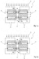
- Fig. 2 is shown in a schematic cross-sectional view, as a larger number of blocks 4 (similar to in Fig. 1 formed) with two piezoelectric elements 5 for forming a linearly arranged energy transfer unit 12 with respective intermediate electric coils 2 can be arranged linearly.
- four blocks 4 are used, wherein the number of blocks 4 may also be different (such as 3, 5, 6, 7, 8, 9 or 10 blocks 4).
- an electrical coil 2 is arranged, whereas on the outer sides 11 of the linearly arranged power transmission unit 12, no electric coils 2 are provided. This can of course be designed differently, ie with an electric coil 2 on one or both outer sides 11th
- linear coil power transmission unit 12 are used in each case connected so that they are alternately in the opposite Sense of electric current to be traversed.
- the electric coils 2a, 2c are thus connected in the same direction, whereas the middle electric coil 2b is connected opposite to the electric coils 2a, 2c.
- the linear array 12 is characterized significantly more effective.
- a third possible embodiment of a power transmission unit 13 is shown.
- the electric coil 14 "lying" between two piezo elements 5 is arranged.
- the force exerted by the piezoelectric elements 5 contacting conductor portions 15a, 15b of the electric coil 14 is therefore not based on a torque of the electric coil (as in the in Fig. 1 and Fig. 2 rather, it is based on shrinking ("pumping") the electrical coil 14. Since, as already mentioned, typically only micrometer motions are required, such "pumping" may be required. However, the electric coil 14 can be realized without causing excessive material fatigue of the conductor of the electric coil 14.
- the electric coil 14 does not necessarily have to have a circular cross-section here.
- substantially rectangular and / or "flattened oval" cross-sectional shapes can also be used here.
Description
Die Erfindung betrifft eine Energieübertragungsvorrichtung, die zumindest eine Energieeintragseinrichtung und zumindest eine als Piezoelementeinrichtung ausgebildete Energieerzeugungseinrichtung aufweist.The invention relates to an energy transmission device which has at least one energy input device and at least one energy generating device designed as a piezo element device.
Zur Durchführung unterschiedlichster Messaufgaben und Regelungsaufgaben ist es erforderlich Energie, insbesondere elektrische Energie, an unterschiedlichsten Orten bereitzustellen. Hierzu werden in vielen Fällen elektrische Kabel verwendet, mit denen elektrische Energie beispielsweise aus dem öffentlichen Stromnetz zu den Orten geführt wird, an denen diese benötigt wird, also beispielsweise zu den mit elektrischer Energie zu versorgenden Messgeräten bzw. Regeleinrichtungen. Bei speziellen Einsatzorten bzw. Anwendungsgebieten kann jedoch eine Zuführung elektrischer Energie mithilfe von elektrischen Kabeln zu Problemen führen oder sogar unmöglich sein.To carry out a wide variety of measurement tasks and control tasks, it is necessary to provide energy, in particular electrical energy, at a wide variety of locations. For this purpose, electrical cables are used in many cases, with which electrical energy is conducted, for example, from the public power grid to the places where it is needed, so for example, to be supplied with electrical energy meters or control devices. However, in specific locations or applications, supplying electrical energy using electrical cables can be a problem or even impossible.
Derartige besondere Einsatzbedingungen können beispielsweise vorliegen, wenn eine galvanische Isolierung der mit elektrischer Energie zu versorgenden Komponenten erfolgen muss, insbesondere dann, wenn sehr hohe Potenzialdifferenzen vorliegen. Derartige Bedingungen bestehen beispielsweise bei Hochspannungsanlagen oder im Forschungsumfeld beispielsweise bei Van-de-Graaff-Beschleunigern.Such special conditions of use may be present, for example, if galvanic insulation of the components to be supplied with electrical energy has to take place, in particular if very high potential differences exist. Such conditions exist for example in high-voltage systems or in the research environment, for example in Van-de-Graaff accelerators.
Probleme können auch dann auftreten, wenn besonders problematische Umgebungsbedingungen vorliegen. Dies kann beispielsweise dann der Fall sein, wenn die elektrischen Kabel durch elektromagnetisch stark belastete Gebiete geführt werden müssen, so dass die elektrischen Kabel Störsignale aufnehmen können, die wiederum zu Problemen bei Regelungskomponenten bzw. zu einer Verschlechterung der Messgenauigkeit von Messgeräten führen können, wenn keine vergleichsweise aufwändigen Glättungs- bzw. Filterungsmaßnahmen ergriffen werden.Problems can also occur if there are particularly problematic environmental conditions. This may be the case, for example, when the electrical cables have to be routed through electromagnetically heavily loaded areas, so that the electrical cables can pick up interference signals, which in turn can lead to problems with control components or a deterioration in the measuring accuracy of measuring devices, if none comparatively complex smoothing or filtering measures are taken.
In Fällen, in denen die mit elektrischer Energie zu versorgenden Komponenten in sehr starken Magnetfeldern angeordnet sind, sind darüber hinaus klassische Transformatoren nicht sinnvoll verwendbar. Dies hängt damit zusammen, dass Transformatoren in aller Regel mit ferromagnetischen Kernen bzw. Jochen ausgebildet werden, um deren Wirkungsgrad zu erhöhen. Befindet sich ein derartiges ferromagnetisches Material jedoch in einem starken Magnetfeld, so kann sich dieses bereits aufgrund des externen Magnetfelds im Sättigungsbereich befinden. Dementsprechend ist das ferromagnetische Material zu Zwecken der Spannungstransformation "nicht verfügbar", so dass es zu entsprechenden Problemen kommt.In cases where the components to be supplied with electrical energy are arranged in very strong magnetic fields, conventional transformers can not be usefully used beyond that. This is due to the fact that transformers are usually formed with ferromagnetic cores or yokes, in order to increase their efficiency. However, such a ferromagnetic material is in a strong magnetic field, this may already be due to the external magnetic field in the saturation region. Accordingly, the ferromagnetic material is "unavailable" for purposes of stress transformation, so that there are corresponding problems.
Für den Einsatz unter EMV-Bedingungen (EMV = elektromagnetische Verträglichkeit) und/oder bei sehr starken (statischen) Magnetfeldern (typischerweise Magnetfeldern mit Feldstärken ≥ 0,1 Tesla, 0,25 Tesla, 0,5 Tesla, 0,75 Tesla, 1,0 Tesla, 1,25 Tesla, 1,5 Tesla, 1,75 Tesla bzw. 2,0 Tesla) wurde bereits die Verwendung von so genannten Piezowandlern vorgeschlagen. Bei diesen wird ein Piezokristall mit elektrischer Energie (in aller Regel einem elektrischen Wechselstrom) versorgt, so dass dieser seine Größe ändert, insbesondere zu schwingen anfängt. Dieser Piezokristall ist mechanisch mit einem zweiten Piezokristall verbunden, so dass die mechanische Verformung (Schwingung) des ersten Piezokristalls auf den zweiten Piezokristall übertragen wird und hier zur Erzeugung einer entsprechenden elektrischen Spannung führt, die über elektrische Kontakte abgeführt werden kann. Derartige Piezowandler weisen in aller Regel eine sehr gute elektromagnetische Verträglichkeit auch unter schwierigen EMV-Bedingungen auf. Darüber hinaus sind Piezokristalle meist sehr unempfindlich gegenüber starken externen Magnetfeldern sowie gegenüber radioaktiver Strahlung (insbesondere Gamma-Strahlung). Obwohl Piezowandler viele Vorteile aufweisen, besteht ein großer Nachteil im Eigenfrequenzspektrum (insbesondere Resonanzfrequenzen) bzw. Schwingungsverhalten (in Abhängigkeit von der angelegten elektrischen Spannung) des Eingangs-Piezokristalls, der elektrische Energie in mechanische Schwingungen wandelt. Die dadurch entstehenden Übertragungscharakteristiken von Piezowandlern erweisen sich in der praktischen Anwendung oftmals als problematisch bis hin zur Unbrauchbarkeit derartiger Piezowandler bei bestimmten Einsatzgebieten.For use under EMC conditions (EMV = Electromagnetic Compatibility) and / or for very strong (static) magnetic fields (typically magnetic fields with field strengths ≥ 0.1 Tesla, 0.25 Tesla, 0.5 Tesla, 0.75 Tesla, 1 , 0 Tesla, 1.25 Tesla, 1.5 Tesla, 1.75 Tesla respectively 2.0 Tesla), the use of so-called piezo transducers has already been proposed. In these, a piezocrystal is supplied with electrical energy (usually an electrical alternating current), so that it changes its size, in particular begins to oscillate. This piezocrystal is mechanically connected to a second piezocrystal, so that the mechanical deformation (oscillation) of the first piezocrystal is transferred to the second piezocrystal and leads here to the generation of a corresponding electrical voltage which can be dissipated via electrical contacts. Such piezo transducers usually have a very good electromagnetic compatibility even under difficult EMC conditions. In addition, piezocrystals are usually very insensitive to strong external magnetic fields and to radioactive radiation (especially gamma radiation). Although piezoelectric transducers have many advantages, there is a major disadvantage in the natural frequency spectrum (in particular resonant frequencies) or oscillation behavior (depending on the applied electrical voltage) of the input piezoelectric crystal, which converts electrical energy into mechanical oscillations. The resulting transmission characteristics of piezoelectric transducers often prove to be problematic in practice, even as far as the usability of such piezoelectric transducers in certain applications.
In der wissenschaftlichen Veröffentlichung "
In der internationalen Patentanmeldung
In der europäischen Patentanmeldung
In der deutschen Offenlegungsschrift
Es besteht daher nach wie vor ein Bedürfnis an Energieerzeugungsvorrichtungen, welche Vorteile gegenüber im Stand der Technik bekannter Energieerzeugungsvorrichtungen aufweisen.There is therefore still a need for power generation devices which have advantages over prior art power generation devices.
Es wird vorgeschlagen, eine Energieübertragungsvorrichtung, welche zumindest eine Energieeintragseinrichtung und zumindest eine als Piezoelementeinrichtung ausgebildete Energieerzeugungseinrichtung aufweist, derart auszubilden, dass die zumindest eine Energieeintragseinrichtung zumindest teilweise als elektrische Magnetfelderzeugungseinrichtung ausgebildet ist und derart ausgebildet und eingerichtet ist, dass sie zumindest teilweise und/oder zumindest zeitweise unter Wirkvermittlung eines externen magnetischen Felds arbeitet, derart, dass sie eine Lorentzkraft auf die zumindest eine Energieerzeugungseinrichtung ausübt. Erfindungsgemäß ist die in die zumindest eine Energieeintragseinrichtung eingetragene Energie zumindest zeitweise und/oder zumindest teilweise im Wesentlichen von der gleichen Energieform wie die von der zumindest einen Energieerzeugungseinrichtung erzeugten und ausgegebenen Energie. Es handelt sich dabei im Wesentlichen um elektrische Energie.It is proposed that an energy transmission device which has at least one energy input device and at least one energy generating device designed as a piezo element device be designed in such a way that the at least one energy input device is at least partially designed as an electric magnetic field generating device and configured and arranged such that it is at least partially and / or at least temporarily operates under active mediation of an external magnetic field, such that it exerts a Lorentz force on the at least one power generating device. According to the invention, the energy introduced into the at least one energy input device is at least temporarily and / or at least partially essentially of the same energy form as the energy generated and output by the at least one energy generating device. These are essentially electrical energy.
Es wird also im Wesentlichen elektrische Energie in die Energieübertragungsvorrichtung eingespeist und von der Energieübertragungsvorrichtung im Wesentlichen elektrische Energie ausgegeben. Auch wenn die grundsätzliche Energieform sich dabei nicht ändert, so ist es dennoch möglich (und gegebenenfalls auch von Vorteil), dass bei der Energieübertragungsvorrichtung beispielsweise die elektrische Spannung, die elektrische Stromstärke und/oder die Frequenz und/oder die Amplitudenform und/oder das Pulsweitenverhältnis zumindest zeitweise und/oder zumindest teilweise geändert wird. Eine derartige Änderung kann dabei in beide Richtungen erfolgen, so dass beispielsweise die elektrische Spannung "herauf transformiert" bzw. "herunter transformiert" werden kann. Auch ist es gegebenenfalls möglich, dass sich die Richtung und/oder das Verhältnis der Wertänderung verändern, insbesondere in Abhängigkeit von einem Steuerimpuls (also zum Beispiel entsprechend einer Nutzervorgabe). Unter einer Piezoelementeinrichtung sind im vorliegenden Zusammenhang gegebenenfalls sämtliche Mittel zu verstehen, welche eine mechanische Formveränderung, eine mechanische Größenveränderung und/oder einen angelegten mechanischen Druck in ein elektrisches Signal umwandeln können (gegebenenfalls auch umgekehrt), wobei diese Umwandlung vorzugsweise direkt und unmittelbar aufgrund des inneren Aufbaus der Piezoelementeinrichtung erfolgt. Insbesondere kann unter einer Piezoelementeinrichtung ein Piezokristall bzw. eine geeignete Anordnung von mehreren Piezokristallen verstanden werden, wobei gegebenenfalls auch weitere "Hilfskomponenten" dazu gehören können. Unter einer Wirkvermittlung mit einem externen Feld ist im Rahmen der vorliegenden Beschreibung insbesondere zu verstehen, dass die betreffende Komponente (bzw. die betreffenden Komponenten) beim nicht-Vorhandensein des betreffenden externen Felds im Wesentlichen nicht funktionstüchtig wären, zumindest jedoch einen deutlich schlechteren Wirkungsgrad aufweisen würden und/oder sonstige nachteilige Eigenschaften auftreten würden. Es kommt also in aller Regel zu einer Art Wechselwirkung zwischen der betreffenden Komponente (den betreffenden Komponenten) und dem externen Feld. Bei dem externen Feld kann es sich grundsätzlich um ein beliebiges Feld, wie beispielsweise ein elektrisches Feld, ein elektrostatisches Feld, ein elektromagnetisches Feld, ein magnetisches Feld, ein Kraftfeld und dergleichen handeln. Im Übrigen ist es nicht ausgeschlossen, dass das externe Feld auch zumindest teilweise und/oder zumindest zeitweise von der Energieübertragungsvorrichtung selbst erzeugt wird. Üblich ist es jedoch in der Regel, dass zumindest zeitweise ein in der Regel größerer Teil des externen Felds (bzw. der Großteil des externen Felds bzw. im Wesentlichen das gesamte externe Feld) durch externe Einrichtungen erzeugt wird, wobei es bevorzugt ist, wenn das externe Feld zu anderweitigen Zwecken ohnehin erzeugt werden muss bzw. vorhanden ist. Rein beispielhaft können in diesem Zusammenhang Kernspintomographen oder Ablenkmagneten bei Teilchenbeschleunigern genannt werden, wo funktionsbedingt starke (zum größeren Teil statische) Magnetfelder erzeugt werden müssen.Thus, essentially electrical energy is fed into the energy transmission device and substantially electrical energy is output by the energy transmission device. Even if the basic form of energy does not change, it is nevertheless possible (and possibly also advantageous) for the electrical transmission device to have, for example, the electrical voltage, the electric current intensity and / or the frequency and / or the amplitude shape and / or the pulse width ratio is changed at least temporarily and / or at least partially. Such a change can take place in both directions, so that, for example, the electrical voltage can be "transformed up" or "down transformed". It may also be possible that the direction and / or the ratio of the change in value change, in particular as a function of a control pulse (that is, for example, according to a user specification). Under a piezoelectric device in the present context, if appropriate, all means to understand, which can convert a mechanical change in shape, a mechanical change in size and / or an applied mechanical pressure in an electrical signal (possibly vice versa), this conversion preferably directly and directly due to the internal Structure of the piezo element device takes place. In particular, a piezoelectric element can be understood to mean a piezoelectric crystal or a suitable arrangement of a plurality of piezoelectric crystals, it also being possible for further "ancillary components" to be included therein. In the context of the present description, an active mediation with an external field is to be understood in particular as meaning that the component in question (or the relevant components) would not be essentially functional in the absence of the relevant external field, but would at least have a significantly poorer efficiency and / or other adverse properties would occur. Thus, there is usually a kind of interaction between the component in question (the components concerned) and the external field. In principle, the external field can be any field, such as an electric field, an electrostatic field, an electromagnetic field Field, a magnetic field, a force field and the like act. Incidentally, it is not excluded that the external field is also generated at least partially and / or at least temporarily by the energy transmission device itself. However, it is usually customary for a usually larger part of the external field (or the majority of the external field or essentially the entire external field) to be generated at least temporarily by external devices, it being preferred if this is the case external field for other purposes anyway needs to be generated or is available. Purely by way of example, magnetic resonance tomographs or deflection magnets may be mentioned in particle accelerators, where functionally strong (for the most part static) magnetic fields have to be generated.
Dadurch, dass die zumindest eine Energieeintragseinrichtung derart ausgebildet und eingerichtet ist, dass sie zumindest teilweise und/oder zumindest zeitweise unter Wirkvermittlung eines magnetischen Felds arbeitet, ist die Energieübertragungsvorrichtung besonders geeignet, um beispielsweise im Zusammenhang mit Kernspintomographen, Teilchenbeschleunigern (hier insbesondere im Zusammenhang mit Ablenkmagneten, Fokussierungsmagneten und dergleichen) und dergleichen betrieben zu werden. In einem solchen Fall kann nicht nur vorteilhafter Weise auf eine magnetische Abschirmung verzichtet werden, sondern eine derartige Abschirmung kann im Gegenteil sogar unerwünscht sein. Hierdurch kann Bauraum gespart werden, Oberflächen von denen Gase desorbieren können können vermieden werden, Kosten können reduziert werden und dergleichen. Bei dem magnetischen Feld kann es sich in an sich beliebiger Weise um ein magnetisches Wechselfeld, ein (im Wesentlichen) statisches magnetisches Feld, sowie um ein (im Wesentlichen) statisches magnetisches Feld, welches mit einem gewissen wechselnden Anteil überlagert ist, handeln. Im Übrigen ist es selbstverständlich möglich, dass zusätzlich zum magnetischen Feld auch weitere Felder überlagert sein können.By virtue of the fact that the at least one energy input device is designed and set up such that it operates at least partially and / or at least temporarily under the action of a magnetic field, the energy transmission device is particularly suitable, for example in conjunction with magnetic resonance tomographs, particle accelerators (here in particular in connection with deflection magnets , Focusing magnets and the like) and the like. In such a case, not only can advantageously be dispensed with magnetic shielding, but such shielding may even be undesirable on the contrary. This space can be saved, surfaces from which can desorb gases can be avoided, costs can be reduced and the like. The magnetic field may be in any desired manner a magnetic alternating field, a (substantially) static magnetic field, as well as a (substantially) static magnetic field, which is superimposed with a certain varying proportion. Incidentally, it is of course possible that in addition to the magnetic field and other fields can be superimposed.
Bei der Energieübertragungsvorrichtung ist die zumindest eine Energieeintragseinrichtung zumindest teilweise als elektrische Magnetfelderzeugungseinrichtung ausgebildet, wobei es bevorzugt ist, wenn die Energieeintragseinrichtung zumindest teilweise als elektrische Leiterschleifeneinrichtung und/oder zumindest teilweise als elektrische Spuleneinrichtung ausgebildet ist. Hierdurch kann es zu einer Wechselwirkung beispielsweise eines externen Magnetfelds und dem "lokal erzeugten" Magnetfeld kommen, so dass beispielsweise Kräfte auf die Energieeintragseinrichtung und/oder auf sonstige Komponenten der Energieübertragungsvorrichtung (insbesondere mit der Energieeintragseinrichtung in Kontakt stehende Bauteile) resultieren können. Ein derartiger Aufbau kann sich als einerseits besonders einfach, andererseits aber auch als vergleichsweise effektiv und gegebenenfalls auch als verschleißarm erweisen. Hierdurch können gegebenenfalls besonders kleine Bauformen der Energieübertragungsvorrichtung realisiert werden. Ein weiterer Vorteil kann sich durch die Richtungsabhängigkeit des bzw. der jeweiligen magnetischen Felder ergeben, so dass hier gewisse Richtungen "ausgeklammert" werden können bzw. umgekehrt bevorzugt werden können, was gegebenenfalls von Vorteil sein kann. Rein grundsätzlich kann es sich bei der Magnetfelderzeugungsvorrichtung um eine beliebige elektrische Magnetfelderzeugungseinrichtungen handeln, derart, dass durch Variation eines angelegten elektrischen Stroms ein unterschiedlich starkes "lokales" Magnetfeld erzeugt werden kann. Als geeignete Bauform hierfür haben sich insbesondere elektrische Leiterschleifen und/oder elektrische Spulen (bevorzugt ohne ferromagnetischen Kern) erwiesen.In the energy transmission device, the at least one energy input device is at least partially designed as an electric magnetic field generating device, wherein it is preferred if the energy input device is at least partially designed as an electrical conductor loop device and / or at least partially as an electrical coil device. This can lead to an interaction of, for example, an external magnetic field and the "locally generated" magnetic field, so that, for example Forces may result on the energy input device and / or other components of the energy transmission device (in particular with the energy input device in contact components). Such a construction may prove to be particularly simple on the one hand, but on the other hand also comparatively effective and possibly also wear-resistant. As a result, if necessary, particularly small designs of the energy transmission device can be realized. A further advantage may result from the directional dependence of the respective magnetic field (s), so that certain directions can be "excluded" here, or vice versa, which may be advantageous. In principle, the magnetic field generating device can be any desired electric magnetic field generating device, such that a varying "local" magnetic field can be generated by varying an applied electrical current. As a suitable design for this particular electrical conductor loops and / or electrical coils (preferably without ferromagnetic core) have been found.
Eine weiter bevorzugte Ausbildungsform der Energieübertragungsvorrichtung ergibt sich, wenn zumindest eine Energieeintragseinrichtung zumindest teilweise als feldverstärkungseinrichtungsfreie Energieeintragseinrichtung ausgebildet ist. Typischerweise wird bei elektrisch betriebenen Magnetfelderzeugungseinrichtungen (wie beispielsweise bei Spulen) zur Verstärkung des durch diese erzeugten "lokalen" Magnetfelds ein ferromagnetisches Materialstück (beispielsweise Ferritkerne, magnetische Joche aus ferromagnetischem Material und dergleichen) verwendet. Eine derartige Ausführungsform kann sich zwar als vorteilhaft erweisen, wenn vergleichsweise schwache externe Felder vorhanden sind. Wenn jedoch zumindest zeitweise sehr starke externe Felder (insbesondere Magnetfelder) vorhanden sind, so können sich derartige Feldverstärkungseinrichtungen bereits in einem (teilweisen) Sättigungszustand befinden, so dass die Effektivität der Energieeintragseinrichtung - und damit schlussendlich der Energieübertragungsvorrichtung - bis hin zur weitgehenden Unbrauchbarkeit verringert werden kann. Dies ist naturgemäß von Nachteil. Daher ist es sinnvoll, dass insbesondere im Zusammenhang mit starken externen Feldern (insbesondere Magnetfeldern) feldverstärkungseinrichtungsfreie Komponenten (insbesondere feldverstärkungseinrichtungsfreie Energieeintragseinrichtungen) genutzt werden, also beispielsweise Luft-Leiterschleifen bzw. Luft-Spuleneinrichtungen.A further preferred embodiment of the energy transmission device results when at least one energy input device is at least partially designed as a field gain device-free energy input device. Typically, electrically powered magnetic field generating devices (such as coils) use a piece of ferromagnetic material (such as ferrite cores, ferromagnetic magnetic yokes, and the like) to enhance the "local" magnetic field generated thereby. Such an embodiment may prove advantageous when comparatively weak external fields are present. However, if at least at times very strong external fields (in particular magnetic fields) are present, such field amplification devices can already be in a (partial) saturation state, so that the effectiveness of the energy input device - and thus ultimately of the energy transmission device - can be reduced to the point of largely unusability , This is of course disadvantageous. Therefore, it makes sense that in particular in connection with strong external fields (in particular magnetic fields) field reinforcement device-free components (in particular field gain device-free energy input devices) are used, so for example air conductor loops or air coil devices.
Weiterhin ist es von Vorteil, wenn bei der Energieübertragungsvorrichtung zumindest eine Energieeintragseinrichtung derart ausgebildet und eingerichtet ist, dass diese zumindest teilweise und/oder zumindest zeitweise mit elektrischer Energie beaufschlagt wird. Bei der elektrischen Energie kann es sich insbesondere um elektrische Wechselspannung handeln. Insbesondere ist es möglich durch unterschiedliche Formen der Wechselspannung (beispielsweise Sinuskurve, Sägezahnkurve, Rechteckkurve und dergleichen) und/oder durch unterschiedliche Pulsweitenverhältnisse und/oder durch unterschiedliche Frequenzen ein unterschiedliches Verhalten der Energieeintragseinrichtung zu bewirken. Hierdurch ist es möglich, dass beispielsweise eine mit der Energieeintragseinrichtung gekoppelte Energieerzeugungseinrichtung unterschiedliche elektrische Signale, insbesondere unterschiedlich im Hinblick auf Spannung, Stromstärke, Frequenz, Wellenform, Pulsweitenverhältnis und dergleichen erzeugen kann. Auf diese Weise kann die Energieübertragungsvorrichtung besonders flexibel genutzt werden. Weiterhin ist elektrische Energie im Zusammenhang mit elektrischen bzw. elektronischen Aufbauten in aller Regel ohnehin vorhanden, so dass diese vergleichsweise einfach "abgezweigt" werden kann. Weiterhin ist es möglich, dass bei einem Betrieb mit elektrischer Energie die zumindest eine Energieeintragseinrichtung besonders einfach aufgebaut sein kann.Furthermore, it is advantageous if, in the energy transmission device, at least one energy input device is designed and set up such that it is at least partially and / or at least temporarily exposed to electrical energy. The electrical energy may in particular be electrical alternating voltage. In particular, it is possible to effect a different behavior of the energy input device by different forms of the alternating voltage (for example sine curve, sawtooth curve, rectangular curve and the like) and / or by different pulse width ratios and / or by different frequencies. This makes it possible, for example, for an energy generating device coupled to the energy input device to generate different electrical signals, in particular different with regard to voltage, current intensity, frequency, waveform, pulse width ratio and the like. In this way, the energy transmission device can be used very flexibly. Furthermore, electrical energy is generally present in any case in connection with electrical or electronic structures, so that they can be "branched off" comparatively easily. Furthermore, it is possible that at a Operation with electrical energy, the at least one energy input device can be particularly simple.
Eine bevorzugte Ausführungsform der Energieübertragungsvorrichtung kann sich ergeben, wenn diese derart ausgebildet und eingerichtet ist, dass die zumindest eine Energieeintragseinrichtung zumindest teilweise und/oder zumindest zeitweise über zumindest eine Bewegung, insbesondere zumindest teilweise und/oder zumindest zeitweise über zumindest eine Translationsbewegung und/oder zumindest teilweise und/oder zumindest zeitweise über zumindest eine Rotationsbewegung auf die zumindest eine Energieerzeugungseinrichtung einwirkt, insbesondere mechanisch einwirkt. Eine derartige Wirkungsweise kann sich beispielsweise ergeben, wenn zumindest Teile einer elektrischen Leiterschleife bzw. einer Spule im Wesentlichen bündig mit einer Oberfläche eines Piezokristalls in Kontakt gebracht werden. Beim Anlegen eines entsprechenden elektrischen Stroms an die Leiterschleife bzw. die Spule kann sich dann im entsprechenden (Teil-)Bereich der Leiterschleife/Spule ein mechanischer Druck beziehungsweise eine mechanische Zugspannung im entsprechenden korrespondierenden Oberflächenbereich des Piezokristalls ergeben. Auf diese Weise kann eine einfache und besonders effektive Anordnung realisiert werden, wobei üblicherweise hohe Wirkungsgrade erzielt werden können.A preferred embodiment of the energy transmission device may result if it is designed and set up such that the at least one energy input device at least partially and / or at least temporarily via at least one movement, in particular at least partially and / or at least temporarily via at least one translational movement and / or at least partially and / or at least temporarily acts on at least one rotational movement on the at least one energy generating device, in particular acts mechanically. Such an effect can, for example, result if at least parts of an electrical conductor loop or a coil are brought into contact substantially flush with a surface of a piezocrystal. When a corresponding electric current is applied to the conductor loop or the coil, a mechanical pressure or a mechanical tensile stress in the corresponding corresponding surface region of the piezocrystal can then result in the corresponding (partial) region of the conductor loop / coil. In this way, a simple and particularly effective arrangement can be realized, usually high efficiencies can be achieved.
Eine weitere bevorzugte Ausführungsform der Energieübertragungsvorrichtung kann sich ergeben, wenn diese derart ausgebildet und eingerichtet ist, dass die zumindest eine Energieeintragseinrichtung zumindest teilweise und/oder zumindest zeitweise über eine Verformungsbewegung auf die zumindest eine Energieerzeugungseinrichtung einwirkt, insbesondere mechanisch einwirkt. Hierbei kann es sich beispielsweise um eine Formveränderung der entsprechenden Energieeintragseinrichtung (insbesondere eine Leiterschleife bzw. eine elektrische Spule) handeln, beispielsweise derart, dass sich eine rechteckartige Formgebung sich zu einem Oval zu verformen versucht oder dergleichen. Auch ist es möglich, dass eine Größenveränderung der Energieeintragseinrichtung auftritt, wie beispielsweise bei einer kreisförmigen Leiterschleife bzw. Spule eine Radiuserhöhung bzw. Radiusverringerung. In diesem Zusammenhang sollte darauf hingewiesen werden, dass im Zusammenhang mit Piezoelementeinrichtungen üblicherweise Stellbewegungen im Mikrometerbereich ausreichend sind, so dass auch bei einer Größenveränderung einer Energieeintragseinrichtung üblicherweise eine hohe Standzeit der Energieeintragseinrichtung realisiert werden kann, auch wenn grundsätzlich Materialermüdungseffekte auftreten können bzw. in aller Regel auftreten. Selbstverständlich sind auch Mischformen aus den genannten "Extremen" "Bewegung" und "Verformung" möglich.A further preferred embodiment of the energy transmission device may result if it is constructed and arranged such that the at least one energy input device acts on the at least one energy generation device, in particular mechanically, at least partially and / or at least temporarily via a deformation movement. This may be, for example, a change in shape of the corresponding energy input device (in particular a conductor loop or an electrical coil), for example, such that a rectangular shape attempts to deform into an oval or similar. It is also possible that a change in size of the energy input device occurs, such as, for example, in the case of a circular conductor loop or coil, a radius increase or a radius reduction. In this context, it should be pointed out that adjustment movements in the micrometer range are usually sufficient in connection with piezoelectric element devices, so that a long service life of the energy input device can usually be realized even if the size of an energy input device changes, even if material fatigue effects can generally occur or generally occur , Of course, mixed forms of the mentioned "extremes""movement" and "deformation" are possible.
Weiterhin ist es von Vorteil, wenn bei der Energieübertragungsvorrichtung eine Mehrzahl von Energieeintragseinrichtungen und/oder eine Mehrzahl von Energieerzeugungseinrichtungen vorgesehen wird. Mit einem derartigen Aufbau können insbesondere unterschiedliche Übersetzungsverhältnisse bzw. Untersetzungsverhältnisse der eingegebenen und ausgegebenen Energien, Spannungen, Stromstärken, Frequenzen, Pulsweitenverhältnisse usw. realisiert werden. Beispielsweise kann durch einen entsprechenden mechanischen Aufbau eine Spannungserhöhung bzw. eine Spannungserniedrigung um einen bestimmten Faktor (bzw. in einem gewissen Faktorbereich) realisiert werden. Auch ist es möglich, dass die insgesamt übertragbare Energiemenge (bzw. Spannung und/oder Stromstärke) erhöht werden kann, was bei bestimmten Anwendungen von Vorteil sein kann. Insbesondere ist es auch möglich, dass die Verschaltung in Abhängigkeit von einem Steuersignal verändert werden kann.Furthermore, it is advantageous if a plurality of energy input devices and / or a plurality of energy production devices is provided in the energy transmission device. With such a structure, in particular, different gear ratios or reduction ratios of the input and output energies, voltages, currents, frequencies, pulse width ratios, etc. can be realized. For example, by a corresponding mechanical structure, a voltage increase or a voltage reduction by a certain factor (or in a certain factor range) can be realized. It is also possible that the total transferable amount of energy (or voltage and / or current) can be increased, which may be advantageous in certain applications. In particular, it is also possible that the interconnection can be changed in dependence on a control signal.
Eine weitere bevorzugte Ausführungsform einer Energieübertragungsvorrichtung kann sich ergeben, wenn diese eine lineare Anordnung von zumindest einer Energieeintragseinrichtung und zumindest einer Energieerzeugungseinrichtung aufweist, insbesondere eine lineare Anordnung von einer Mehrzahl von Energieeintragseinrichtungen und/oder einer Mehrzahl von Energieerzeugungseinrichtungen. Mit einem derartigen Aufbau ist es einerseits möglich eine besonders kompakte Bauform zu realisieren. Darüber hinaus ist es möglich, dass Kombinationseffekte realisiert werden können, wie beispielsweise dass bei einer Leiterschleife zwei Seiten der Leiterschleife einen mechanischen Druck (und damit eine Energiegewinnung im dazu benachbarten Piezoelement) erzeugen können, auch wenn es sich um unterschiedliche Piezoelemente handelt. Hierdurch kann die Kompaktheit und Effektivität der resultierenden Energieübertragungsvorrichtung in der Regel nochmals gesteigert werden.A further preferred embodiment of an energy transmission device can result if it has a linear arrangement of at least one energy input device and at least one energy generating device, in particular a linear arrangement of a plurality energy input devices and / or a plurality of power generation devices. With such a structure, it is possible on the one hand to realize a particularly compact design. In addition, it is possible that combination effects can be realized, such as that in a conductor loop two sides of the conductor loop can generate a mechanical pressure (and thus an energy in the adjacent piezoelectric element), even if it is different piezoelectric elements. As a result, the compactness and effectiveness of the resulting energy transmission device can usually be further increased.
Im Folgenden wird die Erfindung anhand vorteilhafter Ausführungsbeispiele und unter Bezugnahme auf die beigefügte Zeichnung näher erläutert. Es zeigen:
- Fig. 1:
- ein erstes Ausführungsbeispiel einer Energieübertragungseinheit in einem schematischen Querschnitt zu zwei unterschiedlichen Zeitpunkten;
- Fig. 2:
- ein zweites Ausführungsbeispiel einer Energieübertragungseinheit in einem schematischen Querschnitt;
- Fig. 3:
- ein drittes Ausführungsbeispiel einer Energieübertragungseinheit in einem schematischen Querschnitt.
- Fig. 1:
- a first embodiment of a power transmission unit in a schematic cross section at two different times;
- Fig. 2:
- a second embodiment of a power transmission unit in a schematic cross section;
- 3:
- A third embodiment of a power transmission unit in a schematic cross section.
In
Die Energieübertragungseinheit 1 ist beispielsweise in einer Vorrichtung (nicht dargestellt) angeordnet, in welcher im Betrieb ein stärkeres Magnetfeld 3 auftritt. Bei einer derartigen Vorrichtung kann es sich beispielsweise um Ablenkmagneten eines Teilchenbeschleunigers oder um das (größtenteils statische) Magnetfeld eines Kernspintomographen handeln. Durch die Anordnung der Energieübertragungseinheit 1 in der entsprechenden Vorrichtung ist die Energieübertragungseinheit 1 dementsprechend dem Magnetfeld 3 ausgesetzt.The
Die Energieübertragungseinheit 1 besteht aus zwei Blöcken 4, in denen im vorliegenden Ausführungsbeispiel jeweils zwei Piezoelemente 5 (hierbei kann es sich um kommerziell erhältliche Piezoelemente 5 handeln) angeordnet sind. Die Piezoelemente 5 sind unter Zwischenanordnung eines Füllmaterials 6 zueinander beanstandet angeordnet, wobei Piezoelemente 5 und Füllmaterial 6 im vorliegend dargestellten Ausführungsbeispiel fest miteinander verbunden sind, so dass sich jeweils ein einteiliger Block 4 ergibt. An den Außenseiten der Piezoelemente 5 ist jeweils eine Elektrode 7 angeordnet, so dass die in den Piezoelementen 5 erzeugten elektrischen Spannungen abgeleitet werden und an Kontaktklemmen 8 abgegriffen werden können. In der vorliegend dargestellten
Wie weiterhin
Wird nun die elektrische Spule 2 mit einem elektrischen Strom beaufschlagt (elektrische Stromzuführungsleiter zur Spule 2 sind aus Übersichtsgründen nicht dargestellt), so ergibt sich (je nach Phasenlage des angelegten elektrischen Stroms, insbesondere Wechselstroms) beispielsweise die in
In
Wenn durch Anlegen einer Wechselspannung an die elektrische Spule 2 die Situation von
Der Strom durch die elektrische Spule 2 erzeugt im Übrigen die Kraft F, die sich aus F = B · i · l · N berechnet. Dabei ist F die Kraft 10, die die Leiterbereiche 9a, 9b auf die Piezoelemente 5 ausüben, B ist die Magnetfeldstärke des Magnetfelds 3, i ist der Strom durch die elektrische Spule 2 und I ist die Leiterlänge der Leiterbereiche 9a, 9b über den Piezoelementen 5. N ist die Windungszahl der elektrischen Spule 2.Incidentally, the current through the
In
Es wird darauf hingewiesen, dass die bei der in
In
Wie bereits im Zusammenhang mit den in
Für sämtliche in den
Für das Magnetfeld 3 können typischerweise Magnetfelder im Bereich von H = 0,5 Tesla verwendet werden. Typische Windungszahlen für die elektrischen Spulen 2, 14 sind N = 100-200 Windungen. Als typische Stromstärke für die elektrischen Spulen 2, 14 können Ströme im Bereich von i = 10 mA verwendet werden. Die Frequenz des elektrischen Stroms, mit dem die elektrischen Spulen 2, 14 beaufschlagt werden, liegt typischerweise im Bereich zwischen F = 10 kHz und 100 kHz.For all in the
Magnetic fields in the range of H = 0.5 Tesla can typically be used for the
- 1.1.
- EnergieübertragungseinheitPower transmission unit
- 2.Second
- Elektrische SpuleElectric coil
- 3.Third
- Magnetfeldmagnetic field
- 4.4th
- Blockblock
- 5.5th
- Piezoelementpiezo element
- 6.6th
- Füllmaterialfilling material
- 7.7th
- Elektrodeelectrode
- 8.8th.
- Kontaktklemmecontact terminal
- 9.9th
- LeiterbereichHead of
- 10.10th
- LorentzkraftLorentz force
- 11.11th
- Außenseiteoutside
- 12.12th
- EnergieübertragungseinheitPower transmission unit
- 13.13th
- EnergieübertragungseinheitPower transmission unit
- 14.14th
- Elektrische SpuleElectric coil
- 15.15th
- LeiterbereichHead of
Claims (8)
- Energy transmission apparatus (1, 12, 13), comprising at least one energy input device (2) and at least one energy generation device (4, 5) implemented as a piezoelectric element device, characterised in that the at least one energy input device (2) is implemented at least partially as an electrical magnetic field generation device (2), and is implemented and arranged in such a way that it works at least partially and/or at least some of the time under the active mediation of an external magnetic field (3) in order to exercise a Lorentz force on the at least one energy generation device (4, 5).
- Energy transmission apparatus (1, 12, 13) according to Claim 1, characterised in that the at least one energy input device (2) is implemented at least partly as an electric conductor loop device and/or at least partially as an electric coil device (2).
- Energy transmission apparatus (1, 12, 13) according to one of the previous claims, in particular according to Claim 2, characterised in that at least one energy input device (2) is implemented at least partially as an energy input device (2) that has no field enhancement device.
- Energy transmission apparatus (1, 12, 13) according to one of the previous claims, characterised in that at least one energy input device (2) is implemented and arranged in such a way that it is at least partially and/or at least some of the time impinged upon by electrical energy.
- Energy transmission apparatus (1, 12, 13) according to one of the previous claims, characterised in that it is implemented and arranged in such a way that the at least one energy input device (2) acts, in particular acts mechanically (10), on the at least one energy generation device (4, 5), at least partially and/or at least some of the time through at least one movement, in particular through at least partially and/or at least some of the time through at least one translation movement and/or at least partially and/or at least some of the time through at least one rotation movement (Fig. 1, Fig. 2).
- Energy transmission apparatus (1, 12, 13) according to one of the previous claims, characterised in that it is implemented and arranged in such a way that the at least one energy input device (2) acts, in particular acts mechanically (10), on the at least one energy generation device (4, 5) at least partially and/or a least some of the time through a deforming movement (Fig. 3).
- Energy transmission apparatus (1, 12, 13) according to one of the previous claims, characterised by a plurality of energy input devices (2) and/or by a plurality of energy generation devices (4, 5).
- Energy transmission device (1, 12, 13) according to one of the previous claims, in particular according to Claim 7, characterised by a linear arrangement (1, 12, 13) of at least one energy input device (2) and at least one energy generation device (4, 5), in particular by a plurality of energy input devices (2) and/or a plurality of energy generation devices (4, 5).
Applications Claiming Priority (2)
| Application Number | Priority Date | Filing Date | Title |
|---|---|---|---|
| DE102011052923.3A DE102011052923B4 (en) | 2011-08-23 | 2011-08-23 | Power transmission unit |
| PCT/EP2012/064866 WO2013026652A1 (en) | 2011-08-23 | 2012-07-30 | Energy transmitting unit |
Publications (2)
| Publication Number | Publication Date |
|---|---|
| EP2748922A1 EP2748922A1 (en) | 2014-07-02 |
| EP2748922B1 true EP2748922B1 (en) | 2016-03-23 |
Family
ID=46642499
Family Applications (1)
| Application Number | Title | Priority Date | Filing Date |
|---|---|---|---|
| EP12745812.3A Active EP2748922B1 (en) | 2011-08-23 | 2012-07-30 | Energy transmitting unit |
Country Status (6)
| Country | Link |
|---|---|
| EP (1) | EP2748922B1 (en) |
| DE (1) | DE102011052923B4 (en) |
| DK (1) | DK2748922T3 (en) |
| ES (1) | ES2569670T3 (en) |
| PL (1) | PL2748922T3 (en) |
| WO (1) | WO2013026652A1 (en) |
Families Citing this family (2)
| Publication number | Priority date | Publication date | Assignee | Title |
|---|---|---|---|---|
| DE102012106376B4 (en) * | 2012-07-16 | 2016-09-08 | Gsi Helmholtzzentrum Für Schwerionenforschung Gmbh | Device for generating energy with piezo elements |
| DE102018126909B4 (en) * | 2018-10-29 | 2023-07-27 | Hahn-Schickard-Gesellschaft für angewandte Forschung e.V. | Energy collector for obtaining electrical energy from magnetic fields that change over time |
Citations (2)
| Publication number | Priority date | Publication date | Assignee | Title |
|---|---|---|---|---|
| DE102007059179A1 (en) * | 2007-12-06 | 2009-06-10 | Helmut Obieglo | Medium and/or material process flow guiding and/or influencing device i.e. power machine, has permanent magnet exerting cyclic movements in fixed housing and delivering generated electrical resulting potential as net energy |
| EP2221087A2 (en) * | 2009-02-20 | 2010-08-25 | Biotronik CRM Patent AG | Active medical implant |
Family Cites Families (9)
| Publication number | Priority date | Publication date | Assignee | Title |
|---|---|---|---|---|
| DE3390497C2 (en) * | 1983-06-03 | 1989-03-16 | Piezo Electric Prod | Piezoelectric generator for extracting energy from a fluid stream |
| DE19910619A1 (en) * | 1999-03-10 | 2000-09-21 | Siemens Ag | Electrical energy-via-sound supply method for electrical load e.g. for current and voltage measurement in communal power supply equipment |
| DE10025028C2 (en) * | 2000-05-20 | 2002-03-28 | Josef Roediger | Electromagnetic solid state voltage converter |
| DE10103952A1 (en) * | 2001-01-30 | 2002-10-02 | Enocean Gmbh | Device for supplying energy to a sensor |
| US20060049717A1 (en) * | 2004-09-08 | 2006-03-09 | Frank Liebenow | Transformer |
| DE102004055625B4 (en) * | 2004-11-11 | 2015-04-02 | Baumer Hübner GmbH | Voltage generator with a piezoelectric transducer element |
| CA2649880C (en) * | 2006-06-22 | 2015-10-27 | Cooper Tire & Rubber Co. | Magnetostrictive/piezo remote power generation, battery and method |
| WO2009039293A1 (en) * | 2007-09-18 | 2009-03-26 | University Of Florida Research Foundation, Inc. | Dul-mode piezoelectric/magnetic vibrational energy harvester |
| DE102009010144A1 (en) * | 2009-02-23 | 2010-08-26 | Li-Tec Battery Gmbh | Method and charging device for charging a motor vehicle battery |
-
2011
- 2011-08-23 DE DE102011052923.3A patent/DE102011052923B4/en not_active Expired - Fee Related
-
2012
- 2012-07-30 DK DK12745812.3T patent/DK2748922T3/en active
- 2012-07-30 PL PL12745812.3T patent/PL2748922T3/en unknown
- 2012-07-30 EP EP12745812.3A patent/EP2748922B1/en active Active
- 2012-07-30 WO PCT/EP2012/064866 patent/WO2013026652A1/en active Application Filing
- 2012-07-30 ES ES12745812.3T patent/ES2569670T3/en active Active
Patent Citations (2)
| Publication number | Priority date | Publication date | Assignee | Title |
|---|---|---|---|---|
| DE102007059179A1 (en) * | 2007-12-06 | 2009-06-10 | Helmut Obieglo | Medium and/or material process flow guiding and/or influencing device i.e. power machine, has permanent magnet exerting cyclic movements in fixed housing and delivering generated electrical resulting potential as net energy |
| EP2221087A2 (en) * | 2009-02-20 | 2010-08-25 | Biotronik CRM Patent AG | Active medical implant |
Also Published As
| Publication number | Publication date |
|---|---|
| ES2569670T3 (en) | 2016-05-12 |
| DE102011052923A1 (en) | 2013-02-28 |
| WO2013026652A1 (en) | 2013-02-28 |
| PL2748922T3 (en) | 2016-09-30 |
| DE102011052923B4 (en) | 2016-11-24 |
| EP2748922A1 (en) | 2014-07-02 |
| DK2748922T3 (en) | 2016-06-27 |
Similar Documents
| Publication | Publication Date | Title |
|---|---|---|
| DE102012106376B4 (en) | Device for generating energy with piezo elements | |
| DE102013219536A1 (en) | Charging station for wireless energy-related coupling of an electrically driven vehicle | |
| DE112013006545T5 (en) | Magnetostrictive vibration power generation device | |
| DE3833342A1 (en) | Piezoelectric motor | |
| EP2748922B1 (en) | Energy transmitting unit | |
| DE2010196A1 (en) | Vibration converter for flexural vibrators | |
| DE102010021094B4 (en) | Improved electrical energy extraction from piezoelectric energy converters with the possibility of polarity reversal of these energy converters | |
| DE102008032666A1 (en) | Capacitive winding for electric motors, transformers and electromagnets | |
| DE102011110870A1 (en) | Electromechanical energy converter | |
| EP2606565A2 (en) | Electric dc/dc-converter for a mobile application | |
| EP2003709B1 (en) | Piezo converter with primary automatic control and pertinent piezo transformer | |
| EP2562772A2 (en) | Inductive unit | |
| WO2011134789A1 (en) | Piezogenerator comprising different piezoelements and electronic circuit | |
| EP0984160B1 (en) | Voltage transformer | |
| EP3123607B1 (en) | Modular converter system for an electric supply network | |
| DE102006032392B4 (en) | Method for galvanically separated information and energy transmission between two electronic circuit units | |
| DE102013101020B4 (en) | Ultrasonic actuator and ultrasonic motor with such a Ultraschallaktor | |
| EP2852988B1 (en) | Generators made of electroactive polymers (eap) in differential assembly | |
| DE102008038989A1 (en) | Electrical system i.e. magnetic resonance device for e.g. medical diagnosis of patient, has load electrically connected with power supply over piezoelectric direct current-direct current converters by intermediate circuit voltage line | |
| DE102013203836A1 (en) | Piezoelectric ultrasonic vibration element | |
| WO2012045543A1 (en) | Voltage converter comprising at least one electromechanically acting switch, and a corresponding method | |
| DE102010048781B4 (en) | High voltage generator and method of operation | |
| DE102017211936A1 (en) | Flat adjustable capacitor for magnetic resonance tomograph | |
| DE102014113925A1 (en) | energy converters | |
| DE102008043667A1 (en) | Multilayer actuator i.e. piezoelectric motor, for window lifting drive of motor vehicle, has electrode planes comprising two electrode sections controlled independent of each other, where sections are arranged on collecting electrodes |
Legal Events
| Date | Code | Title | Description |
|---|---|---|---|
| PUAI | Public reference made under article 153(3) epc to a published international application that has entered the european phase |
Free format text: ORIGINAL CODE: 0009012 |
|
| 17P | Request for examination filed |
Effective date: 20140225 |
|
| AK | Designated contracting states |
Kind code of ref document: A1 Designated state(s): AL AT BE BG CH CY CZ DE DK EE ES FI FR GB GR HR HU IE IS IT LI LT LU LV MC MK MT NL NO PL PT RO RS SE SI SK SM TR |
|
| DAX | Request for extension of the european patent (deleted) | ||
| 17Q | First examination report despatched |
Effective date: 20150320 |
|
| GRAJ | Information related to disapproval of communication of intention to grant by the applicant or resumption of examination proceedings by the epo deleted |
Free format text: ORIGINAL CODE: EPIDOSDIGR1 |
|
| GRAP | Despatch of communication of intention to grant a patent |
Free format text: ORIGINAL CODE: EPIDOSNIGR1 |
|
| GRAP | Despatch of communication of intention to grant a patent |
Free format text: ORIGINAL CODE: EPIDOSNIGR1 |
|
| INTG | Intention to grant announced |
Effective date: 20151001 |
|
| GRAS | Grant fee paid |
Free format text: ORIGINAL CODE: EPIDOSNIGR3 |
|
| GRAA | (expected) grant |
Free format text: ORIGINAL CODE: 0009210 |
|
| AK | Designated contracting states |
Kind code of ref document: B1 Designated state(s): AL AT BE BG CH CY CZ DE DK EE ES FI FR GB GR HR HU IE IS IT LI LT LU LV MC MK MT NL NO PL PT RO RS SE SI SK SM TR |
|
| REG | Reference to a national code |
Ref country code: GB Ref legal event code: FG4D Free format text: NOT ENGLISH |
|
| REG | Reference to a national code |
Ref country code: CH Ref legal event code: EP |
|
| REG | Reference to a national code |
Ref country code: AT Ref legal event code: REF Ref document number: 784032 Country of ref document: AT Kind code of ref document: T Effective date: 20160415 Ref country code: CH Ref legal event code: NV Representative=s name: E. BLUM AND CO. AG PATENT- UND MARKENANWAELTE , CH |
|
| REG | Reference to a national code |
Ref country code: IE Ref legal event code: FG4D Free format text: LANGUAGE OF EP DOCUMENT: GERMAN |
|
| REG | Reference to a national code |
Ref country code: DE Ref legal event code: R096 Ref document number: 502012006423 Country of ref document: DE |
|
| REG | Reference to a national code |
Ref country code: ES Ref legal event code: FG2A Ref document number: 2569670 Country of ref document: ES Kind code of ref document: T3 Effective date: 20160512 |
|
| REG | Reference to a national code |
Ref country code: DK Ref legal event code: T3 Effective date: 20160623 |
|
| REG | Reference to a national code |
Ref country code: SE Ref legal event code: TRGR |
|
| REG | Reference to a national code |
Ref country code: FR Ref legal event code: PLFP Year of fee payment: 5 |
|
| REG | Reference to a national code |
Ref country code: LT Ref legal event code: MG4D |
|
| REG | Reference to a national code |
Ref country code: NL Ref legal event code: MP Effective date: 20160323 |
|
| PG25 | Lapsed in a contracting state [announced via postgrant information from national office to epo] |
Ref country code: NO Free format text: LAPSE BECAUSE OF FAILURE TO SUBMIT A TRANSLATION OF THE DESCRIPTION OR TO PAY THE FEE WITHIN THE PRESCRIBED TIME-LIMIT Effective date: 20160623 Ref country code: HR Free format text: LAPSE BECAUSE OF FAILURE TO SUBMIT A TRANSLATION OF THE DESCRIPTION OR TO PAY THE FEE WITHIN THE PRESCRIBED TIME-LIMIT Effective date: 20160323 Ref country code: FI Free format text: LAPSE BECAUSE OF FAILURE TO SUBMIT A TRANSLATION OF THE DESCRIPTION OR TO PAY THE FEE WITHIN THE PRESCRIBED TIME-LIMIT Effective date: 20160323 Ref country code: GR Free format text: LAPSE BECAUSE OF FAILURE TO SUBMIT A TRANSLATION OF THE DESCRIPTION OR TO PAY THE FEE WITHIN THE PRESCRIBED TIME-LIMIT Effective date: 20160624 |
|
| PG25 | Lapsed in a contracting state [announced via postgrant information from national office to epo] |
Ref country code: LV Free format text: LAPSE BECAUSE OF FAILURE TO SUBMIT A TRANSLATION OF THE DESCRIPTION OR TO PAY THE FEE WITHIN THE PRESCRIBED TIME-LIMIT Effective date: 20160323 Ref country code: LT Free format text: LAPSE BECAUSE OF FAILURE TO SUBMIT A TRANSLATION OF THE DESCRIPTION OR TO PAY THE FEE WITHIN THE PRESCRIBED TIME-LIMIT Effective date: 20160323 Ref country code: NL Free format text: LAPSE BECAUSE OF FAILURE TO SUBMIT A TRANSLATION OF THE DESCRIPTION OR TO PAY THE FEE WITHIN THE PRESCRIBED TIME-LIMIT Effective date: 20160323 Ref country code: RS Free format text: LAPSE BECAUSE OF FAILURE TO SUBMIT A TRANSLATION OF THE DESCRIPTION OR TO PAY THE FEE WITHIN THE PRESCRIBED TIME-LIMIT Effective date: 20160323 |
|
| PG25 | Lapsed in a contracting state [announced via postgrant information from national office to epo] |
Ref country code: EE Free format text: LAPSE BECAUSE OF FAILURE TO SUBMIT A TRANSLATION OF THE DESCRIPTION OR TO PAY THE FEE WITHIN THE PRESCRIBED TIME-LIMIT Effective date: 20160323 Ref country code: IS Free format text: LAPSE BECAUSE OF FAILURE TO SUBMIT A TRANSLATION OF THE DESCRIPTION OR TO PAY THE FEE WITHIN THE PRESCRIBED TIME-LIMIT Effective date: 20160723 |
|
| PG25 | Lapsed in a contracting state [announced via postgrant information from national office to epo] |
Ref country code: CZ Free format text: LAPSE BECAUSE OF FAILURE TO SUBMIT A TRANSLATION OF THE DESCRIPTION OR TO PAY THE FEE WITHIN THE PRESCRIBED TIME-LIMIT Effective date: 20160323 Ref country code: PT Free format text: LAPSE BECAUSE OF FAILURE TO SUBMIT A TRANSLATION OF THE DESCRIPTION OR TO PAY THE FEE WITHIN THE PRESCRIBED TIME-LIMIT Effective date: 20160725 Ref country code: SK Free format text: LAPSE BECAUSE OF FAILURE TO SUBMIT A TRANSLATION OF THE DESCRIPTION OR TO PAY THE FEE WITHIN THE PRESCRIBED TIME-LIMIT Effective date: 20160323 Ref country code: RO Free format text: LAPSE BECAUSE OF FAILURE TO SUBMIT A TRANSLATION OF THE DESCRIPTION OR TO PAY THE FEE WITHIN THE PRESCRIBED TIME-LIMIT Effective date: 20160323 Ref country code: SM Free format text: LAPSE BECAUSE OF FAILURE TO SUBMIT A TRANSLATION OF THE DESCRIPTION OR TO PAY THE FEE WITHIN THE PRESCRIBED TIME-LIMIT Effective date: 20160323 |
|
| PG25 | Lapsed in a contracting state [announced via postgrant information from national office to epo] |
Ref country code: BE Free format text: LAPSE BECAUSE OF NON-PAYMENT OF DUE FEES Effective date: 20160731 |
|
| REG | Reference to a national code |
Ref country code: DE Ref legal event code: R097 Ref document number: 502012006423 Country of ref document: DE |
|
| PLBE | No opposition filed within time limit |
Free format text: ORIGINAL CODE: 0009261 |
|
| STAA | Information on the status of an ep patent application or granted ep patent |
Free format text: STATUS: NO OPPOSITION FILED WITHIN TIME LIMIT |
|
| PG25 | Lapsed in a contracting state [announced via postgrant information from national office to epo] |
Ref country code: BG Free format text: LAPSE BECAUSE OF FAILURE TO SUBMIT A TRANSLATION OF THE DESCRIPTION OR TO PAY THE FEE WITHIN THE PRESCRIBED TIME-LIMIT Effective date: 20160623 |
|
| 26N | No opposition filed |
Effective date: 20170102 |
|
| PG25 | Lapsed in a contracting state [announced via postgrant information from national office to epo] |
Ref country code: MC Free format text: LAPSE BECAUSE OF FAILURE TO SUBMIT A TRANSLATION OF THE DESCRIPTION OR TO PAY THE FEE WITHIN THE PRESCRIBED TIME-LIMIT Effective date: 20160323 |
|
| REG | Reference to a national code |
Ref country code: IE Ref legal event code: MM4A |
|
| PG25 | Lapsed in a contracting state [announced via postgrant information from national office to epo] |
Ref country code: SI Free format text: LAPSE BECAUSE OF FAILURE TO SUBMIT A TRANSLATION OF THE DESCRIPTION OR TO PAY THE FEE WITHIN THE PRESCRIBED TIME-LIMIT Effective date: 20160323 |
|
| REG | Reference to a national code |
Ref country code: FR Ref legal event code: PLFP Year of fee payment: 6 |
|
| PG25 | Lapsed in a contracting state [announced via postgrant information from national office to epo] |
Ref country code: IE Free format text: LAPSE BECAUSE OF NON-PAYMENT OF DUE FEES Effective date: 20160730 |
|
| PG25 | Lapsed in a contracting state [announced via postgrant information from national office to epo] |
Ref country code: LU Free format text: LAPSE BECAUSE OF NON-PAYMENT OF DUE FEES Effective date: 20160730 |
|
| PG25 | Lapsed in a contracting state [announced via postgrant information from national office to epo] |
Ref country code: CY Free format text: LAPSE BECAUSE OF FAILURE TO SUBMIT A TRANSLATION OF THE DESCRIPTION OR TO PAY THE FEE WITHIN THE PRESCRIBED TIME-LIMIT Effective date: 20160323 Ref country code: HU Free format text: LAPSE BECAUSE OF FAILURE TO SUBMIT A TRANSLATION OF THE DESCRIPTION OR TO PAY THE FEE WITHIN THE PRESCRIBED TIME-LIMIT; INVALID AB INITIO Effective date: 20120730 |
|
| PG25 | Lapsed in a contracting state [announced via postgrant information from national office to epo] |
Ref country code: MK Free format text: LAPSE BECAUSE OF FAILURE TO SUBMIT A TRANSLATION OF THE DESCRIPTION OR TO PAY THE FEE WITHIN THE PRESCRIBED TIME-LIMIT Effective date: 20160323 Ref country code: MT Free format text: LAPSE BECAUSE OF FAILURE TO SUBMIT A TRANSLATION OF THE DESCRIPTION OR TO PAY THE FEE WITHIN THE PRESCRIBED TIME-LIMIT Effective date: 20160323 |
|
| REG | Reference to a national code |
Ref country code: FR Ref legal event code: PLFP Year of fee payment: 7 |
|
| PG25 | Lapsed in a contracting state [announced via postgrant information from national office to epo] |
Ref country code: TR Free format text: LAPSE BECAUSE OF FAILURE TO SUBMIT A TRANSLATION OF THE DESCRIPTION OR TO PAY THE FEE WITHIN THE PRESCRIBED TIME-LIMIT Effective date: 20160323 Ref country code: AL Free format text: LAPSE BECAUSE OF FAILURE TO SUBMIT A TRANSLATION OF THE DESCRIPTION OR TO PAY THE FEE WITHIN THE PRESCRIBED TIME-LIMIT Effective date: 20160323 |
|
| PGFP | Annual fee paid to national office [announced via postgrant information from national office to epo] |
Ref country code: IT Payment date: 20230731 Year of fee payment: 12 Ref country code: GB Payment date: 20230724 Year of fee payment: 12 Ref country code: ES Payment date: 20230821 Year of fee payment: 12 Ref country code: CH Payment date: 20230802 Year of fee payment: 12 Ref country code: AT Payment date: 20230718 Year of fee payment: 12 |
|
| PGFP | Annual fee paid to national office [announced via postgrant information from national office to epo] |
Ref country code: SE Payment date: 20230724 Year of fee payment: 12 Ref country code: PL Payment date: 20230718 Year of fee payment: 12 Ref country code: FR Payment date: 20230724 Year of fee payment: 12 Ref country code: DK Payment date: 20230724 Year of fee payment: 12 Ref country code: DE Payment date: 20230720 Year of fee payment: 12 |