EP2748440B1 - Abgasbehandlungseinrichtung, verfahren zur aufbereitung von abgas und kraftfahrzeug - Google Patents
Abgasbehandlungseinrichtung, verfahren zur aufbereitung von abgas und kraftfahrzeug Download PDFInfo
- Publication number
- EP2748440B1 EP2748440B1 EP12748167.9A EP12748167A EP2748440B1 EP 2748440 B1 EP2748440 B1 EP 2748440B1 EP 12748167 A EP12748167 A EP 12748167A EP 2748440 B1 EP2748440 B1 EP 2748440B1
- Authority
- EP
- European Patent Office
- Prior art keywords
- exhaust gas
- catalytic converter
- reduction
- reduction catalytic
- treatment device
- Prior art date
- Legal status (The legal status is an assumption and is not a legal conclusion. Google has not performed a legal analysis and makes no representation as to the accuracy of the status listed.)
- Active
Links
- 238000000034 method Methods 0.000 title claims description 9
- 238000006722 reduction reaction Methods 0.000 claims description 113
- 238000002485 combustion reaction Methods 0.000 claims description 64
- 230000003197 catalytic effect Effects 0.000 claims description 55
- 238000001816 cooling Methods 0.000 claims description 51
- 239000003638 chemical reducing agent Substances 0.000 claims description 28
- 238000011144 upstream manufacturing Methods 0.000 claims description 16
- 239000002826 coolant Substances 0.000 claims description 10
- 238000010531 catalytic reduction reaction Methods 0.000 claims description 9
- 230000001590 oxidative effect Effects 0.000 claims 5
- 239000007789 gas Substances 0.000 description 112
- 239000003054 catalyst Substances 0.000 description 76
- 230000003647 oxidation Effects 0.000 description 19
- 238000007254 oxidation reaction Methods 0.000 description 19
- QGZKDVFQNNGYKY-UHFFFAOYSA-N Ammonia Chemical compound N QGZKDVFQNNGYKY-UHFFFAOYSA-N 0.000 description 14
- IJGRMHOSHXDMSA-UHFFFAOYSA-N Atomic nitrogen Chemical compound N#N IJGRMHOSHXDMSA-UHFFFAOYSA-N 0.000 description 10
- MWUXSHHQAYIFBG-UHFFFAOYSA-N Nitric oxide Chemical class O=[N] MWUXSHHQAYIFBG-UHFFFAOYSA-N 0.000 description 10
- 239000002245 particle Substances 0.000 description 8
- 229910021529 ammonia Inorganic materials 0.000 description 7
- 238000006243 chemical reaction Methods 0.000 description 7
- 238000002347 injection Methods 0.000 description 7
- 239000007924 injection Substances 0.000 description 7
- 239000000446 fuel Substances 0.000 description 5
- 229910052757 nitrogen Inorganic materials 0.000 description 5
- XLYOFNOQVPJJNP-UHFFFAOYSA-N water Substances O XLYOFNOQVPJJNP-UHFFFAOYSA-N 0.000 description 5
- 239000000126 substance Substances 0.000 description 4
- XSQUKJJJFZCRTK-UHFFFAOYSA-N Urea Chemical compound NC(N)=O XSQUKJJJFZCRTK-UHFFFAOYSA-N 0.000 description 3
- 239000003570 air Substances 0.000 description 3
- 239000004202 carbamide Substances 0.000 description 3
- 230000003111 delayed effect Effects 0.000 description 3
- 229910017464 nitrogen compound Inorganic materials 0.000 description 3
- 150000002830 nitrogen compounds Chemical class 0.000 description 3
- 239000002243 precursor Substances 0.000 description 3
- 238000000354 decomposition reaction Methods 0.000 description 2
- 230000002349 favourable effect Effects 0.000 description 2
- 238000010438 heat treatment Methods 0.000 description 2
- 238000004519 manufacturing process Methods 0.000 description 2
- 238000000746 purification Methods 0.000 description 2
- 239000000243 solution Substances 0.000 description 2
- 206010063493 Premature ageing Diseases 0.000 description 1
- 208000032038 Premature aging Diseases 0.000 description 1
- 239000012080 ambient air Substances 0.000 description 1
- 239000007864 aqueous solution Substances 0.000 description 1
- 238000006555 catalytic reaction Methods 0.000 description 1
- 239000003795 chemical substances by application Substances 0.000 description 1
- 238000004140 cleaning Methods 0.000 description 1
- 238000010276 construction Methods 0.000 description 1
- 230000018109 developmental process Effects 0.000 description 1
- 238000011038 discontinuous diafiltration by volume reduction Methods 0.000 description 1
- 238000000265 homogenisation Methods 0.000 description 1
- 239000000203 mixture Substances 0.000 description 1
- 238000005457 optimization Methods 0.000 description 1
- 230000005855 radiation Effects 0.000 description 1
- 238000011946 reduction process Methods 0.000 description 1
- 239000011343 solid material Substances 0.000 description 1
- 238000009827 uniform distribution Methods 0.000 description 1
- WTHDKMILWLGDKL-UHFFFAOYSA-N urea;hydrate Chemical compound O.NC(N)=O WTHDKMILWLGDKL-UHFFFAOYSA-N 0.000 description 1
Images


Classifications
-
- F—MECHANICAL ENGINEERING; LIGHTING; HEATING; WEAPONS; BLASTING
- F01—MACHINES OR ENGINES IN GENERAL; ENGINE PLANTS IN GENERAL; STEAM ENGINES
- F01N—GAS-FLOW SILENCERS OR EXHAUST APPARATUS FOR MACHINES OR ENGINES IN GENERAL; GAS-FLOW SILENCERS OR EXHAUST APPARATUS FOR INTERNAL COMBUSTION ENGINES
- F01N3/00—Exhaust or silencing apparatus having means for purifying, rendering innocuous, or otherwise treating exhaust
- F01N3/08—Exhaust or silencing apparatus having means for purifying, rendering innocuous, or otherwise treating exhaust for rendering innocuous
- F01N3/10—Exhaust or silencing apparatus having means for purifying, rendering innocuous, or otherwise treating exhaust for rendering innocuous by thermal or catalytic conversion of noxious components of exhaust
-
- F—MECHANICAL ENGINEERING; LIGHTING; HEATING; WEAPONS; BLASTING
- F01—MACHINES OR ENGINES IN GENERAL; ENGINE PLANTS IN GENERAL; STEAM ENGINES
- F01N—GAS-FLOW SILENCERS OR EXHAUST APPARATUS FOR MACHINES OR ENGINES IN GENERAL; GAS-FLOW SILENCERS OR EXHAUST APPARATUS FOR INTERNAL COMBUSTION ENGINES
- F01N13/00—Exhaust or silencing apparatus characterised by constructional features ; Exhaust or silencing apparatus, or parts thereof, having pertinent characteristics not provided for in, or of interest apart from, groups F01N1/00 - F01N5/00, F01N9/00, F01N11/00
- F01N13/009—Exhaust or silencing apparatus characterised by constructional features ; Exhaust or silencing apparatus, or parts thereof, having pertinent characteristics not provided for in, or of interest apart from, groups F01N1/00 - F01N5/00, F01N9/00, F01N11/00 having two or more separate purifying devices arranged in series
- F01N13/0097—Exhaust or silencing apparatus characterised by constructional features ; Exhaust or silencing apparatus, or parts thereof, having pertinent characteristics not provided for in, or of interest apart from, groups F01N1/00 - F01N5/00, F01N9/00, F01N11/00 having two or more separate purifying devices arranged in series the purifying devices are arranged in a single housing
-
- F—MECHANICAL ENGINEERING; LIGHTING; HEATING; WEAPONS; BLASTING
- F01—MACHINES OR ENGINES IN GENERAL; ENGINE PLANTS IN GENERAL; STEAM ENGINES
- F01N—GAS-FLOW SILENCERS OR EXHAUST APPARATUS FOR MACHINES OR ENGINES IN GENERAL; GAS-FLOW SILENCERS OR EXHAUST APPARATUS FOR INTERNAL COMBUSTION ENGINES
- F01N3/00—Exhaust or silencing apparatus having means for purifying, rendering innocuous, or otherwise treating exhaust
- F01N3/02—Exhaust or silencing apparatus having means for purifying, rendering innocuous, or otherwise treating exhaust for cooling, or for removing solid constituents of, exhaust
- F01N3/021—Exhaust or silencing apparatus having means for purifying, rendering innocuous, or otherwise treating exhaust for cooling, or for removing solid constituents of, exhaust by means of filters
- F01N3/033—Exhaust or silencing apparatus having means for purifying, rendering innocuous, or otherwise treating exhaust for cooling, or for removing solid constituents of, exhaust by means of filters in combination with other devices
- F01N3/035—Exhaust or silencing apparatus having means for purifying, rendering innocuous, or otherwise treating exhaust for cooling, or for removing solid constituents of, exhaust by means of filters in combination with other devices with catalytic reactors, e.g. catalysed diesel particulate filters
-
- F—MECHANICAL ENGINEERING; LIGHTING; HEATING; WEAPONS; BLASTING
- F01—MACHINES OR ENGINES IN GENERAL; ENGINE PLANTS IN GENERAL; STEAM ENGINES
- F01N—GAS-FLOW SILENCERS OR EXHAUST APPARATUS FOR MACHINES OR ENGINES IN GENERAL; GAS-FLOW SILENCERS OR EXHAUST APPARATUS FOR INTERNAL COMBUSTION ENGINES
- F01N3/00—Exhaust or silencing apparatus having means for purifying, rendering innocuous, or otherwise treating exhaust
- F01N3/08—Exhaust or silencing apparatus having means for purifying, rendering innocuous, or otherwise treating exhaust for rendering innocuous
- F01N3/10—Exhaust or silencing apparatus having means for purifying, rendering innocuous, or otherwise treating exhaust for rendering innocuous by thermal or catalytic conversion of noxious components of exhaust
- F01N3/105—General auxiliary catalysts, e.g. upstream or downstream of the main catalyst
- F01N3/106—Auxiliary oxidation catalysts
-
- F—MECHANICAL ENGINEERING; LIGHTING; HEATING; WEAPONS; BLASTING
- F01—MACHINES OR ENGINES IN GENERAL; ENGINE PLANTS IN GENERAL; STEAM ENGINES
- F01N—GAS-FLOW SILENCERS OR EXHAUST APPARATUS FOR MACHINES OR ENGINES IN GENERAL; GAS-FLOW SILENCERS OR EXHAUST APPARATUS FOR INTERNAL COMBUSTION ENGINES
- F01N3/00—Exhaust or silencing apparatus having means for purifying, rendering innocuous, or otherwise treating exhaust
- F01N3/08—Exhaust or silencing apparatus having means for purifying, rendering innocuous, or otherwise treating exhaust for rendering innocuous
- F01N3/10—Exhaust or silencing apparatus having means for purifying, rendering innocuous, or otherwise treating exhaust for rendering innocuous by thermal or catalytic conversion of noxious components of exhaust
- F01N3/18—Exhaust or silencing apparatus having means for purifying, rendering innocuous, or otherwise treating exhaust for rendering innocuous by thermal or catalytic conversion of noxious components of exhaust characterised by methods of operation; Control
- F01N3/20—Exhaust or silencing apparatus having means for purifying, rendering innocuous, or otherwise treating exhaust for rendering innocuous by thermal or catalytic conversion of noxious components of exhaust characterised by methods of operation; Control specially adapted for catalytic conversion ; Methods of operation or control of catalytic converters
- F01N3/2066—Selective catalytic reduction [SCR]
-
- F—MECHANICAL ENGINEERING; LIGHTING; HEATING; WEAPONS; BLASTING
- F02—COMBUSTION ENGINES; HOT-GAS OR COMBUSTION-PRODUCT ENGINE PLANTS
- F02M—SUPPLYING COMBUSTION ENGINES IN GENERAL WITH COMBUSTIBLE MIXTURES OR CONSTITUENTS THEREOF
- F02M26/00—Engine-pertinent apparatus for adding exhaust gases to combustion-air, main fuel or fuel-air mixture, e.g. by exhaust gas recirculation [EGR] systems
- F02M26/13—Arrangement or layout of EGR passages, e.g. in relation to specific engine parts or for incorporation of accessories
- F02M26/14—Arrangement or layout of EGR passages, e.g. in relation to specific engine parts or for incorporation of accessories in relation to the exhaust system
- F02M26/15—Arrangement or layout of EGR passages, e.g. in relation to specific engine parts or for incorporation of accessories in relation to the exhaust system in relation to engine exhaust purifying apparatus
-
- F—MECHANICAL ENGINEERING; LIGHTING; HEATING; WEAPONS; BLASTING
- F02—COMBUSTION ENGINES; HOT-GAS OR COMBUSTION-PRODUCT ENGINE PLANTS
- F02M—SUPPLYING COMBUSTION ENGINES IN GENERAL WITH COMBUSTIBLE MIXTURES OR CONSTITUENTS THEREOF
- F02M26/00—Engine-pertinent apparatus for adding exhaust gases to combustion-air, main fuel or fuel-air mixture, e.g. by exhaust gas recirculation [EGR] systems
- F02M26/13—Arrangement or layout of EGR passages, e.g. in relation to specific engine parts or for incorporation of accessories
- F02M26/22—Arrangement or layout of EGR passages, e.g. in relation to specific engine parts or for incorporation of accessories with coolers in the recirculation passage
- F02M26/29—Constructional details of the coolers, e.g. pipes, plates, ribs, insulation or materials
- F02M26/30—Connections of coolers to other devices, e.g. to valves, heaters, compressors or filters; Coolers characterised by their location on the engine
-
- F—MECHANICAL ENGINEERING; LIGHTING; HEATING; WEAPONS; BLASTING
- F01—MACHINES OR ENGINES IN GENERAL; ENGINE PLANTS IN GENERAL; STEAM ENGINES
- F01N—GAS-FLOW SILENCERS OR EXHAUST APPARATUS FOR MACHINES OR ENGINES IN GENERAL; GAS-FLOW SILENCERS OR EXHAUST APPARATUS FOR INTERNAL COMBUSTION ENGINES
- F01N2340/00—Dimensional characteristics of the exhaust system, e.g. length, diameter or volume of the apparatus; Spatial arrangements of exhaust apparatuses
- F01N2340/02—Dimensional characteristics of the exhaust system, e.g. length, diameter or volume of the apparatus; Spatial arrangements of exhaust apparatuses characterised by the distance of the apparatus to the engine, or the distance between two exhaust treating apparatuses
-
- F—MECHANICAL ENGINEERING; LIGHTING; HEATING; WEAPONS; BLASTING
- F01—MACHINES OR ENGINES IN GENERAL; ENGINE PLANTS IN GENERAL; STEAM ENGINES
- F01N—GAS-FLOW SILENCERS OR EXHAUST APPARATUS FOR MACHINES OR ENGINES IN GENERAL; GAS-FLOW SILENCERS OR EXHAUST APPARATUS FOR INTERNAL COMBUSTION ENGINES
- F01N2610/00—Adding substances to exhaust gases
- F01N2610/02—Adding substances to exhaust gases the substance being ammonia or urea
-
- F—MECHANICAL ENGINEERING; LIGHTING; HEATING; WEAPONS; BLASTING
- F01—MACHINES OR ENGINES IN GENERAL; ENGINE PLANTS IN GENERAL; STEAM ENGINES
- F01N—GAS-FLOW SILENCERS OR EXHAUST APPARATUS FOR MACHINES OR ENGINES IN GENERAL; GAS-FLOW SILENCERS OR EXHAUST APPARATUS FOR INTERNAL COMBUSTION ENGINES
- F01N2610/00—Adding substances to exhaust gases
- F01N2610/11—Adding substances to exhaust gases the substance or part of the dosing system being cooled
-
- F—MECHANICAL ENGINEERING; LIGHTING; HEATING; WEAPONS; BLASTING
- F01—MACHINES OR ENGINES IN GENERAL; ENGINE PLANTS IN GENERAL; STEAM ENGINES
- F01N—GAS-FLOW SILENCERS OR EXHAUST APPARATUS FOR MACHINES OR ENGINES IN GENERAL; GAS-FLOW SILENCERS OR EXHAUST APPARATUS FOR INTERNAL COMBUSTION ENGINES
- F01N2610/00—Adding substances to exhaust gases
- F01N2610/14—Arrangements for the supply of substances, e.g. conduits
- F01N2610/1453—Sprayers or atomisers; Arrangement thereof in the exhaust apparatus
-
- F—MECHANICAL ENGINEERING; LIGHTING; HEATING; WEAPONS; BLASTING
- F02—COMBUSTION ENGINES; HOT-GAS OR COMBUSTION-PRODUCT ENGINE PLANTS
- F02M—SUPPLYING COMBUSTION ENGINES IN GENERAL WITH COMBUSTIBLE MIXTURES OR CONSTITUENTS THEREOF
- F02M26/00—Engine-pertinent apparatus for adding exhaust gases to combustion-air, main fuel or fuel-air mixture, e.g. by exhaust gas recirculation [EGR] systems
- F02M26/02—EGR systems specially adapted for supercharged engines
- F02M26/04—EGR systems specially adapted for supercharged engines with a single turbocharger
- F02M26/06—Low pressure loops, i.e. wherein recirculated exhaust gas is taken out from the exhaust downstream of the turbocharger turbine and reintroduced into the intake system upstream of the compressor
-
- Y—GENERAL TAGGING OF NEW TECHNOLOGICAL DEVELOPMENTS; GENERAL TAGGING OF CROSS-SECTIONAL TECHNOLOGIES SPANNING OVER SEVERAL SECTIONS OF THE IPC; TECHNICAL SUBJECTS COVERED BY FORMER USPC CROSS-REFERENCE ART COLLECTIONS [XRACs] AND DIGESTS
- Y02—TECHNOLOGIES OR APPLICATIONS FOR MITIGATION OR ADAPTATION AGAINST CLIMATE CHANGE
- Y02A—TECHNOLOGIES FOR ADAPTATION TO CLIMATE CHANGE
- Y02A50/00—TECHNOLOGIES FOR ADAPTATION TO CLIMATE CHANGE in human health protection, e.g. against extreme weather
- Y02A50/20—Air quality improvement or preservation, e.g. vehicle emission control or emission reduction by using catalytic converters
-
- Y—GENERAL TAGGING OF NEW TECHNOLOGICAL DEVELOPMENTS; GENERAL TAGGING OF CROSS-SECTIONAL TECHNOLOGIES SPANNING OVER SEVERAL SECTIONS OF THE IPC; TECHNICAL SUBJECTS COVERED BY FORMER USPC CROSS-REFERENCE ART COLLECTIONS [XRACs] AND DIGESTS
- Y02—TECHNOLOGIES OR APPLICATIONS FOR MITIGATION OR ADAPTATION AGAINST CLIMATE CHANGE
- Y02T—CLIMATE CHANGE MITIGATION TECHNOLOGIES RELATED TO TRANSPORTATION
- Y02T10/00—Road transport of goods or passengers
- Y02T10/10—Internal combustion engine [ICE] based vehicles
- Y02T10/12—Improving ICE efficiencies
Definitions
- the present invention relates to an exhaust gas treatment device for the treatment of exhaust gas of a combustion unit, in particular a diesel engine. Furthermore, the present invention relates to a method for the treatment of exhaust gas of a combustion aggregate by selective catalytic reaction, as well as a motor vehicle in which the inventive method is realized or which has the exhaust gas treatment device according to the invention.
- Thorough and efficient cleaning of the exhaust gases of an internal combustion engine can be achieved by the addition of a reducing agent to the exhaust gas in an exhaust aftertreatment device.
- a reducing agent to the exhaust gas in an exhaust aftertreatment device.
- the nitrogen oxide compounds in the exhaust gas are reduced.
- ammonia is usually used as the reaction agent.
- the nitrogen oxide compounds are reduced together with the ammonia to harmless components such as water and nitrogen.
- the addition of the reducing agent takes place due to confined space conditions in the engine area on a motor vehicle in the underbody area and thus in the exhaust line extending there.
- two-part reduction catalysts or even two separate reduction catalysts are arranged in the underfloor region. This requires a certain production and assembly costs and an increased energy requirement to bring the arranged in the underbody catalyst to the required operating temperature.
- this is realized by an electric heater on or in the reduction catalysts, or by a so-called delayed combustion of fuel in the internal combustion engine.
- the internal combustion engine can not optimally convert the chemical energy of the fuel into kinetic energy of the motor vehicle.
- only about 400 ° C to 450 ° C can be reached by the delayed combustion of fuel in the reduction catalysts.
- the supply of heat to the reduction catalysts serves on the one hand to heat the exhaust gas in order to realize the required reduction and on the other to heat the reducing agent in order to put the water content contained there as quickly as possible in a gas phase.
- the hint can be taken that a high temperature of the exhaust gas is favorable for the operation of the reduction catalyst.
- the DE 103 23 607 A1 teaches an apparatus for purifying exhaust gases of an internal combustion engine having an oxidation catalyst, a particulate filter and a reduction catalyst.
- the reduction catalyst is combined with the particle filter to form a structural unit.
- a device arranged below the engine hood for the purification of exhaust gas of a combustion unit is disclosed.
- an oxidation catalyst, a metering module for introducing a reducing agent and a reduction catalyst are arranged with a particulate filter, which serve the chemical conversion of nitrogen oxide compounds to nitrogen by selective catalytic reduction.
- WO 2012/110720 A1 the pre-notified but post-published documents concern WO 2012/110720 A1 .
- WO 2012/123660 A1 and EP 2 500 538 A1 Nearby devices arranged for the purification of exhaust gas by means of selective catalytic reduction.
- WO 2012/110720 A1 is a U-shaped profile of the exhaust line, in which the individual components are arranged described.
- the document WO 2012/123660 A1 an L-shaped angled exhaust system is shown.
- the document EP 2 500 538 A1 relates to a dosing module associated projection in the exhaust line, which directs a portion of the exhaust stream to the dosing.
- the present invention has for its object to provide a device and a method available with which the nitrogen oxide compounds in the exhaust gas can be reduced in an efficient and cost-effective manner.
- an exhaust gas treatment device for the treatment of exhaust gas of a combustion unit, in particular a diesel engine, wherein the exhaust gas treatment device comprises an exhaust line and arranged therein an oxidation catalyst, a reduction catalyst for selective catalytic reduction and a particulate filter, wherein the oxidation catalyst upstream of the reduction catalyst and the Reduction catalyst upstream of the particulate filter is arranged.
- the reduction catalyst is arranged in the exhaust line in the exhaust gas flow direction so far upstream that the heat of the reduction catalyst passing exhaust gas is sufficient to the Bring reduction catalyst to operating temperature.
- An exhaust gas treatment device according to the invention further comprises a low-pressure exhaust gas recirculation device.
- the low-pressure exhaust gas recirculation device comprises a cooling device.
- the dosing module comprises a cooling unit through which a cooling medium can flow.
- the cooling device is thermally connected to the metering module of the reduction catalytic converter such that the metering module can be cooled by means of the cooling device of the low-pressure exhaust gas recirculation device.
- the cooling unit is designed and designed in such a way that the cooling unit can be fluidically connected to the cooling device of the low-pressure exhaust gas recirculation of the combustion unit.
- the cooling medium of the cooling device can be used for cooling the metering module.
- the heat of the exhaust gas passing through the reduction catalytic converter is the heat of the exhaust gas of the combustion unit, optionally less any heat losses due to the transport of the exhaust gas from the combustion unit to the reduction catalytic converter.
- the exhaust gas heat is thus the heat that arises during the exothermic combustion of the fuel in the combustion unit.
- the invention thus has the advantage that the temperature of the exhaust gas after the exothermic reaction in the combustion unit for decomposition of the reducing agent ammonia can be used, as well as for the reduction of nitrogen compounds together with ammonia to harmless substances such as water and nitrogen.
- the reduction catalyst is preferably a so-called SCR catalyst (selective catalytic reduction), which converts a reducing agent, such as urea, or a reducing agent precursor, such as a urea-water solution in ammonia, which then catalytically selective with nitrogen oxides is converted to nitrogen and water.
- SCR catalyst selective catalytic reduction
- a reducing agent such as urea
- a reducing agent precursor such as a urea-water solution in ammonia
- This exhaust gas treatment device with a low-pressure exhaust gas recirculation device has the advantage of simple and cost-effective exhaust gas from the reduction catalytic converter to the low-pressure exhaust gas recirculation device, in contrast to conventional embodiments with the reduction catalyst on the underbody of a motor vehicle, where increased construction costs incurred for the exhaust gas from the reduction catalyst to low-pressure exhaust gas recirculation device ,
- a low-pressure exhaust gas recirculation device has the advantage over a high-pressure exhaust gas recirculation device that the entire exhaust gas mass flow is available via a turbine for the development of power. In a high-pressure exhaust gas recirculation device, an exhaust gas mass flow upstream of the turbine is removed and returned to the unit. This mass flow can no longer be used to build up the boost pressure.
- such a reduction catalytic converter is arranged in the exhaust gas line in the exhaust gas flow direction so far upstream that the heat of the exhaust gas passing through the reduction catalytic converter is sufficient to realize a decomposition of the reducing agent and / or a reduction of nitrogen compounds together with ammonia to said harmless substances such as water and nitrogen.
- the inventive arrangement of the reduction catalyst downstream of the oxidation catalyst there is the advantage of the additional utilization of the heat of the exhaust gas after the exothermic reaction in the oxidation catalyst. That is, the oxidation catalyst in the operating state, the temperature of the exhaust gas also increases, so that the downstream reduction catalyst is more efficient operable.
- treated exhaust gases pass into the downstream particle filter.
- an exhaust gas turbocharger may additionally be arranged in the exhaust gas line, in which case the reduction catalytic converter is arranged upstream of the exhaust gas turbocharger, since there the temperature of the exhaust gas is higher than at a position downstream of the exhaust gas turbocharger.
- the reduction catalytic converter is arranged so far upstream that the exhaust gas passing through the reduction catalytic converter still has at least 40% and in a particularly preferred embodiment at least 80% of the temperature which the exhaust gas has directly after combustion in the combustion unit.
- the invention thus relates to an exhaust gas treatment device, which, when it is connected to a combustion unit, is flowed through by exhaust gas, wherein the exhaust gas flowing along the reduction catalyst, at least 40% of the temperature having the exhaust gas directly after combustion in the combustion unit ,
- the position of the reduction catalytic converter should preferably be so close to the combustion unit that the exhaust gas passing through the reduction catalytic converter has a temperature of at least 60% and preferably at least 80% and in a particularly favorable embodiment at least 90% of the temperature of the exhaust gas directly after combustion in the combustion unit.
- the exhaust gas line in which the reduction catalytic converter is arranged, preferably has a connection device for connecting the exhaust gas line to the combustion unit, so that the reduction catalytic converter can be arranged as close as possible to the combustion unit.
- the exhaust gas line simple line pieces or other aggregates, such as other catalysts have. Due to the inventive design of the exhaust line, there is the advantage of structurally simpler course of the exhaust system on the underbody of a motor vehicle, since no reduction catalyst must be arranged on the subfloor or under the subfloor.
- thermal energy of the combustion unit can be used, which passes by heat radiation through the ambient air and / or by heat conduction in the solid material of the combustion unit connected to the exhaust gas to the reduction catalyst, so that the temperature of the exhaust gas at least the preferred 40% and preferably over 80% of Temperature of the exhaust gas immediately after the combustion process is.
- the reduction catalytic converter has a metering module for the metered introduction of the reducing agent, wherein the metering module has a cooling unit through which a cooling medium flows and is designed and configured so that the cooling unit can be fluidically connected to a cooling device of the combustion unit, so that Cooling medium from the cooling device for cooling the metering module is usable.
- the introduction of the reducing agent is preferably carried out by injection.
- the metering module is heated by the high temperature of the exhaust gas, the advantages already mentioned are generated.
- the dosing module can be cooled to facilitate and realize the injection of the reducing agent. Cooling is necessary in particular if heating of the metering module above 80 ° C.
- the exhaust gas treatment device is advantageously configured when a cooling device of the combustion unit can also feed the dosing with cooling medium.
- the cooling unit of the dosing may be connected to the cooling of the engine, which can be a simple and efficient as well as weight and volume-saving cooling of the dosing achieved.
- the reduction catalytic converter is arranged on a module connecting the oxidation catalytic converter with the particle filter.
- This module can be a so-called connection funnel.
- Such a module is inexpensive to produce and allows in a simple manner a space-saving arrangement of the dosing of the reduction catalyst.
- This embodiment of the invention is particularly advantageous when the module has a flow-through by the exhaust gas housing, which serves as a housing of the reduction catalyst.
- an injection of the reducing agent can be carried out directly in the housing or in the module.
- the reduction catalytic converter is arranged directly on the particle filter. That is, the particulate filter and the reduction catalyst together form a structural unit having a small volume as a whole because the housing of the particulate filter is also partially used as the housing of the reduction catalyst.
- a method for the treatment of exhaust gas of a combustion unit by selective catalytic reduction available in particular for the treatment of exhaust gas of a diesel engine.
- the exhaust gas flows through an exhaust system coupled to the combustion unit, wherein in the exhaust line an oxidation catalyst upstream of a selective catalytic reduction reduction catalyst and the reduction catalyst upstream of a particulate filter is arranged and the heat of the reduction catalyst passing exhaust gas is used to the reduction catalyst to operating temperature to warm up.
- the metering module is cooled with cooling medium of a cooling device.
- the cooling takes place by means of a low-pressure exhaust gas recirculation device, which comprises the cooling device, which is thermally connected to the dosing of the reduction catalyst such that by means of the cooling device of the low-pressure exhaust gas recirculation device, the metering module is cooled.
- the heat of the exhaust gas is used to heat the reduction catalyst from the cold state and to maintain the operating temperature. It can be provided that only heat of the exhaust gas passing through the reduction catalyst is used to bring the reduction catalyst to operating temperature or to keep.
- a reducing agent precursor such as, for example, gaseous ammonia
- a reducing agent precursor solution such as, for example, an aqueous solution with dissolved urea
- the exhaust gas passing through the reduction catalyst should have a temperature of at least 40%, in particular 60% and in particular embodiment at least 80% and optimally at least 90% of the temperature of the exhaust gas directly after combustion in the combustion aggregate.
- the exhaust gas after leaving the combustion unit is not heated again electrically, but the temperature of the Exhaust gas is due solely to the exothermic reaction in the combustion process in the combustion unit and / or in the oxidation catalyst.
- a lower temperature of the exhaust gas in the reduction catalyst is therefore due only to a heat transfer to the environment of the exhaust line downstream of the combustion unit.
- the reducing agent can be introduced directly into the particle filter or into a module which fluidly connects the oxidation catalyst with the particle filter.
- the reducing agent can be introduced at these points by injection into the exhaust gas.
- a motor vehicle in particular a motor vehicle operated by diesel engine, which has an exhaust gas treatment device according to the invention.
- This motor vehicle may be designed such that the reduction catalytic converter has a metering module for the metered introduction of the reducing agent, wherein the metering module can flow through a cooling module through which a cooling module flows Cooling unit and is fluidly connected to a cooling device of the combustion unit.
- the cooling unit of the dosing module is fluidically connected to a cooler of an exhaust gas recirculation system.
- an already existing cooling device can be used for cooling the dosing module.
- this is designed such that the reduction catalytic converter is arranged above the motor vehicle underbody.
- the motor vehicle preferably has only one reduction catalytic converter, namely the reduction catalytic converter in the exhaust gas treatment device according to the invention, wherein the reduction catalytic converter is arranged very close to the engine and thus no longer in the underbody region.
- FIG. 1 is clearly a combustion unit 10 can be seen, at the exhaust line 20 at a connection means 21, an oxidation catalyst 30 and at this downstream in the exhaust gas flow direction 23 in dash-dotted lines indicated exhaust path 22, a reduction catalyst 50 is arranged on a connecting module 40 or on the housing 41.
- the connecting module 40 leads to a particle filter 60, which is likewise arranged in the exhaust gas path 22.
- the reduction catalyst 50 is disposed on the housing 41 of the connecting module 40 between the oxidation catalyst 30 and the particulate filter 60.
- the reduction catalyst 50 is thus arranged very close to the combustion unit 10 or to the connection device 21, so that heat of the exhaust gas, which arises from the exothermic reaction in the combustion unit 10, is used to bring the reduction catalyst 50 to the required operating temperature or to keep him at this temperature.
- the heat in the reduction catalyst 50 can be used, which is released in an exothermic reaction in the oxidation catalyst 30, since the reduction catalyst 50 connects directly to the oxidation catalyst 30.
- the metering module 51 of the reduction catalyst 50 is connected to the connecting module 40 and to the housing.
- the invention is preferably applied to a transversely mounted or built-diesel engine.
- FIGS. 4 and 5 the expedient embodiment of the housing 41 of the connecting module 40 is shown in order to carry out the reduction in this module 40. It is apparent that essentially only the metering module 51 is to be arranged on the connecting module 40 in order to realize the reduction.
- FIG. 6 It can be seen in which area the actual reduction is realized.
- the exhaust gas flows in the exhaust path 22 along the exhaust gas flow direction 23 through the oxidation catalyst 30 and from there into the housing 41.
- the dosing module 51 of the reduction catalytic converter 50 attached to this housing 41 allows the introduction of the Reducing agent in the hot exhaust gas to realize the reduction.
- the introduction of the reducing agent through the metering module 51 is preferably carried out by an injection 53, as indicated in the cavity of the housing 41.
- a cooling unit 52 on the dosing module 51 can be fluidically connected to a cooling device of the combustion unit 10 and / or connected to a cooling device of a low-pressure exhaust gas recirculation device 70.
- the arrangement of such a low-pressure exhaust gas recirculation device 70 is FIG. 7 removable. It can be seen that the low-pressure exhaust gas recirculation device 70 in the exhaust path 22 connects to the particle filter 60.
- the low-pressure exhaust gas recirculation device 70 advantageously has a cooling device 80 which, as already described, can be connected to the cooling unit 52 of the metering module 51 of the reduction catalytic converter 50. With a suitable design of the cooling device 80 of the combustion unit 10 or the low-pressure exhaust gas recirculation device 70, the metering module 51 of the reduction catalyst 50 can be cooled in a simple and efficient manner, even without space consuming additional cooling units to provide the reduction catalyst 50.
- the reduction catalyst 50 is preferably to be arranged in the engine compartment of the motor vehicle 100, as close as possible to the combustion unit 10. That is, the reduction catalyst 50 is disposed above the motor vehicle underbody 110.
Landscapes
- Engineering & Computer Science (AREA)
- Chemical & Material Sciences (AREA)
- Combustion & Propulsion (AREA)
- Mechanical Engineering (AREA)
- General Engineering & Computer Science (AREA)
- Chemical Kinetics & Catalysis (AREA)
- Health & Medical Sciences (AREA)
- Toxicology (AREA)
- Materials Engineering (AREA)
- Exhaust Gas After Treatment (AREA)
- Processes For Solid Components From Exhaust (AREA)
Description
- Die vorliegende Erfindung betrifft eine Abgasbehandlungseinrichtung zur Aufbereitung von Abgas eines Verbrennungsaggregats, insbesondere eines Dieselmotors. Weiterhin betrifft die vorliegende Erfindung ein Verfahren zur Aufbereitung von Abgas eines Verbrennungsaggregats durch selektive katalytische Reaktion, sowie ein Kraftfahrzeug, in dem das erfindungsgemäße Verfahren realisiert wird beziehungsweise welches die erfindungsgemäße Abgasbehandlungseinrichtung aufweist.
- Eine gründliche und effiziente Reinigung der Abgase einer Verbrennungskraftmaschine kann durch die Zugabe eines Reduktionsmittels zum Abgas in einer Abgasnachbehandlungseinrichtung erfolgen. Dabei werden insbesondere bei mager betriebenen Verbrennungskraftmaschinen, bei denen für die Verbrennung ein Luftüberschuss gegenüber einem stöchiometrischen Kraftstoff-Luft-Gemisch vorliegt, die Stickoxidverbindungen im Abgas reduziert. Als Reaktionsmittel wird üblicherweise Ammoniak verwendet. Bei ausreichenden Temperaturen des Abgases werden die Stickoxidverbindungen zusammen mit dem Ammoniak zu unschädlichen Bestandteilen wie Wasser und Stickstoff reduziert.
- Üblicherweise erfolgt die Zugabe des Reduktionsmittels aufgrund von beengten Bauraumverhältnissen im Motorbereich an einem Kraftfahrzeug in dessen Unterbodenbereich und somit in dem dort verlaufenden Abgasstrang. Oftmals werden dabei zweiteilige Reduktionskatalysatoren oder auch zwei voneinander getrennte Reduktionskatalysatoren im Unterbodenbereich angeordnet. Dies bedingt einen gewissen Fertigungs- und Montageaufwand sowie einen erhöhten Energiebedarf, um die im Unterbodenbereich angeordneten Katalysatoren auf die erforderliche Betriebstemperatur zu bringen. Üblicherweise wird dies durch eine elektrische Heizung an oder in den Reduktionskatalysatoren realisiert, oder durch eine so genannte verschleppte Verbrennung von Treibstoff im Verbrennungsmotor. Das bedeutet, dass der Verbrennungsmotor die chemische Energie des Treibstoffes nicht optimal in Bewegungsenergie des Kraftfahrzeuges umsetzen kann. Zudem sind lediglich zirka 400 °C bis 450 °C durch die verschleppte Verbrennung von Treibstoff in den Reduktionskatalysatoren erreichbar.
- Die Zuführung von Wärme zu den Reduktionskatalysatoren dient zum einen zur Erwärmung des Abgases zwecks Realisierung der erforderlichen Reduktion und zum anderen zur Erwärmung des Reduktionsmittels, um den dort enthaltenen Wasseranteil möglichst schnell in eine Gasphase zu versetzen.
- Aus der
DE 102 50 050 A1 ist bekannt, dass sich die Effizienz des Reduktionskatalysators erhöhen lässt, wenn Verbrennungswärme eines Verbrennungsmotors genutzt wird. - Auch aus der
DE 10 2008 051 496 A1 ist der Hinweis entnehmbar, dass eine hohe Temperatur des Abgases günstig für den Betrieb des Reduktionskatalysators ist. - Die
DE 103 23 607 A1 lehrt eine Vorrichtung zur Reinigung von Abgasen eines Verbrennungsmotors, die einen Oxidationskatalysator, einen Partikelfilter und einen Reduktionskatalysator aufweist. Der Reduktionskatalysator ist dabei mit dem Partikelfilter zu einer baulichen Einheit zusammengefasst. - Im Dokument
FR 2 955 612 A1 - Ferner betreffen die vorangemeldeten, aber nachveröffentlichten Dokumente
WO 2012/110720 A1 ,WO 2012/123660 A1 undEP 2 500 538 A1 motornah angeordnete Vorrichtungen zur Reinigung von Abgas mittels selektiver katalytischer Reduktion. Im DokumentWO 2012/110720 A1 wird ein U-förmiger Verlauf des Abgasstrangs, in welchem die einzelnen Komponenten angeordnet sind, beschrieben. Das DokumentWO 2012/123660 A1 wird ein L-förmig gewinkelter Abgasstrang dargestellt. Das DokumentEP 2 500 538 A1 betrifft einen dem Dosiermodul zugeordneten Vorsprung im Abgasstrang, welcher einen Teil des Abgasstroms zum Dosiermodul leitet. - Die Dokumente
EP 2 105 592 A1 undDE 10 2009 027 185 A1 beschreiben Dosiereinheiten zur Einspritzung von Reduktionsmitteln in die Abgasanlage eines Kraftfahrzeuges. Beide beschriebenen Erfindungen umfassen dabei Kühlrippen, durch welche Luft als Kühlmedium strömt. - Der vorliegenden Erfindung liegt die Aufgabe zugrunde, eine Einrichtung sowie ein Verfahren zur Verfügung zu stellen, mit denen in effizienter und kostengünstiger Weise die Stickoxidverbindungen im Abgas reduziert werden können.
- Diese Aufgabe wird durch die erfindungsgemäße Abgasbehandlungseinrichtung nach Anspruch 1 sowie das erfindungsgemäße Verfahren zur Aufbereitung von Abgas eines Verbrennungsaggregats nach Anspruch 10 gelöst. Ergänzend wird gemäß Anspruch 13 ein Kraftfahrzeug vorgeschlagen, welches eine erfindungsgemäße Abgasbehandlungseinrichtung umfasst.
- Es wird erfindungsgemäß eine Abgasbehandlungseinrichtung zur Aufbereitung von Abgas eines Verbrennungsaggregats, insbesondere eines Dieselmotors, zur Verfügung gestellt, wobei die Abgasbehandlungseinrichtung einen Abgasstrang und darin angeordnet einen Oxidationskatalysator, einen Reduktionskatalysator zur selektiven katalytischen Reduktion und einen Partikelfilter aufweist, wobei der Oxidationskatalysator stromaufwärts des Reduktionskatalysators und der Reduktionskatalysator stromaufwärts des Partikelfilters angeordnet ist. Es ist erfindungsgemäß vorgesehen, dass der Reduktionskatalysator im Abgasstrang in Abgas-Strömungsrichtung derart weit stromaufwärts angeordnet ist, dass die Wärme des den Reduktionskatalysator passierenden Abgases ausreicht, um den Reduktionskatalysator auf Betriebstemperatur zu bringen. Eine erfindungsgemäße Abgasbehandlungseinrichtung weiterhin eine Niederdruck-Abgasrückführungseinrichtung aufweist. Die Niederdruck-Abgasrückführungseinrichtung umfasst eine Kühleinrichtung. Das Dosiermodul umfasst eine von einem Kühlmedium durchströmbare Kühlungseinheit. Die Kühleinrichtung ist derart wärmetechnisch mit dem Dosiermodul des Reduktionskatalysators verbunden, dass mittels der Kühleinrichtung der Niederdruck-Abgasrückführeinrichtung das Dosiermodul kühlbar ist. Die Kühlungseinheit ist derart ausgestaltet und ausgelegt, dass die Kühlungseinheit strömungstechnisch mit der Kühleinrichtung der Niederdruck-Abgasrückführung der Verbrennungsaggregats verbindbar ist. Dabei ist das Kühlmedium vond er Kühlungseinrichtung zur Kühlung des Dosiermoduls nutzbar.
- Die Wärme des den Reduktionskatalysator passierenden Abgases ist dabei die Wärme des Abgases des Verbrennungsaggregats, gegebenenfalls abzüglich etwaiger Wärmeverluste durch den Transport des Abgases vom Verbrennungsaggregat zum Reduktionskatalysator. Die Abgaswärme ist somit die Wärme, die bei der exothermen Verbrennung des Kraftstoffes im Verbrennungsaggregat entsteht. Die Erfindung hat somit den Vorteil, dass die Temperatur des Abgases nach der exothermen Reaktion im Verbrennungsaggregat zur Zersetzung des Reduktionsmittels Ammoniak genutzt werden kann, sowie zur Reduktion von Stickstoffverbindungen zusammen mit Ammoniak zu unschädlichen Stoffen wie Wasser und Stickstoff. Der Reduktionskatalysator ist dabei bevorzugt ein so genannter SCR-Katalysator (selective catalytic reduction), der ein Reduktionsmittel, wie zum Beispiel Harnstoff, beziehungsweise einen Reduktionsmittel-Vorläufer, wie zum Beispiel eine Harnstoff-WasserLösung, in Ammoniak umsetzt, welches dann katalytisch mit Stickoxiden selektiv zu Stickstoff und Wasser konvertiert wird. Dadurch lässt sich der Ausstoß von Stickoxiden um bis zu 90 % verringern.
- Diese erfindungsgemäße Abgasbehandlungseinrichtung mit einer Niederdruck-Abgasrückführungseinrichtung hat den Vorteil der einfachen und kostengünstigen Abgasführung vom Reduktionskatalysator zur Niederdruck-Abgasrückführungseinrichtung, im Gegensatz zu herkömmlichen Ausführungsformen mit dem Reduktionskatalysator am Unterboden eines Kraftfahrzeuges, bei denen erhöhter baulicher Aufwand zur Abgasführung vom Reduktionskatalysator zur Niederdruck-Abgasrückführungseinrichtung anfällt. Eine Niederdruck-Abgasrückführungseinrichtung hat gegenüber einer Hochdruck-Abgasrückführungseinrichtung den Vorteil, dass der gesamte Abgasmassenstrom über eine Turbine für die Leistungsentwicklung zur Verfügung steht. Bei einer Hochdruck-Abgasrückführungseinrichtung wird ein Abgasmassenstrom vor der Turbine entnommen und dem Aggregat wieder zugeführt. Dieser Massenstrom kann nicht mehr zum Aufbau des Ladedrucks genutzt werden.
- Ein solcher Reduktionskatalysator ist erfindungsgemäß im Abgasstrang in Abgas-Strömungsrichtung derart weit stromaufwärts angeordnet, dass die Wärme des den Reduktionskatalysator passierenden Abgases ausreicht, um eine Zersetzung des Reduktionsmittels zu realisieren und/oder eine Reduktion von Stickstoffverbindungen zusammen mit Ammoniak zu den genannten unschädlichen Stoffen wie Wasser und Stickstoff durchzuführen. Durch die erfindungsgemäße Anordnung des Reduktionskatalysators stromabwärts des Oxidationskatalysators ergibt sich der Vorteil der zusätzlichen Ausnutzung der Wärme des Abgases nach der exothermen Reaktion im Oxidationskatalysator. Das heißt, dass der Oxidationskatalysator im Betriebszustand die Temperatur des Abgases ebenfalls erhöht, so dass der nachgeschaltete Reduktionskatalysator noch effizienter betreibbar ist.
- Durch die optimale Reduktion im Reduktionskatalysator gelangen aufbereitete Abgase in den nachgeschalteten Partikelfilter.
- Des Weiteren kann zusätzlich ein Abgasturbolader im Abgasstrang angeordnet sein, wobei in diesem Falle der Reduktionskatalysator stromaufwärts des Abgasturboladers angeordnet ist, da dort die Temperatur des Abgases höher ist als an einer Position stromabwärts des Abgasturboladers.
- Es lässt sich eine Wirkungsgradverbesserung bis auf zirka 90 % des Reduktionskatalysators erreichen, da nicht mehr eine herkömmliche elektrische Aufheizung des Reduktionsmittels oder eine verschleppte Verbrennung notwendig ist, so dass insgesamt der CO2-Ausstoß verringert werden kann und/oder weniger Kraftstoff einzusetzen ist.
- In bevorzugten Ausführungsformen ist vorgesehen, dass der Reduktionskatalysator derart weit stromaufwärts angeordnet ist, dass das den Reduktionskatalysator passierende Abgas noch wenigstens 40 % und in besonders bevorzugter Ausführungsform wenigstens 80 % der Temperatur aufweist, die das Abgas direkt nach der Verbrennung im Verbrennungsaggregat hat. Die Erfindung betrifft somit eine Abgasbehandlungseinrichtung, die, wenn sie an ein Verbrennungsaggregat angeschlossen ist, von Abgas durchströmt ist, wobei das Abgas, welches am Reduktionskatalysator entlang strömt, noch wenigstens 40 % der Temperatur hat, die das Abgas direkt nach der Verbrennung im Verbrennungsaggregat aufweist. Vorzugsweise sollte die Position des Reduktionskatalysators so dicht am Verbrennungsaggregat sein, dass das den Reduktionskatalysator passierende Abgas eine Temperatur von mindestens 60 % und bevorzugt mindestens 80 % und in besonders günstiger Ausgestaltung mindestens 90 % der Temperatur des Abgases direkt nach der Verbrennung im Verbrennungsaggregat hat.
- Der Abgasstrang, in dem der Reduktionskatalysator angeordnet ist, weist vorzugsweise eine Anschlusseinrichtung zum Anschließen des Abgasstranges am Verbrennungsaggregat auf, so dass der Reduktionskatalysator so dicht wie möglich am Verbrennungsaggregat angeordnet werden kann. Dabei kann der Abgasstrang einfache Leitungsstücke oder auch weitere Aggregate, wie zum Beispiel weitere Katalysatoren, aufweisen. Durch die erfindungsgemäße Ausgestaltung des Abgasstranges ergibt sich der Vorteil des konstruktiv einfacheren Verlaufs der Abgasanlage am Unterboden eines Kraftfahrzeuges, da am Unterboden beziehungsweise unter dem Unterboden kein Reduktionskatalysator mehr angeordnet werden muss.
- Durch die erfindungsgemäße frühzeitige Ausnutzung der hohen Temperatur des Abgases ist es möglich, schon wesentlich früher als bisher praktiziert Reduktionsmittel in das Abgas einzubringen und somit früher als bei herkömmlichen Reduktionsverfahren die Stickstoffverbindungen umzuwandeln. Durch die erfindungsgemäße frühe Einbringung des Reduktionsmittels in das Abgas lässt sich optimal eine frühe Homogenisierung des Abgases, das heißt eine gleichmäßige Verteilung,des Reduktionsmittels im Abgas, erreichen, so dass die Reduktion effizient realisiert werden kann.
- Außerdem kann thermische Energie des Verbrennungsaggregates genutzt werden, welche mittels Wärmestrahlung über die Umgebungsluft und/oder mittels Wärmeleitung im festen Material des an das Verbrennungsaggregat angeschlossenen Abgasstrangs zum Reduktionskatalysator gelangt, so dass die Temperatur des Abgases mindestens die bevorzugten 40 % und vorzugsweise über 80 % der Temperatur des Abgases unmittelbar nach dem Verbrennungsprozess beträgt. Durch die effiziente Betriebsweise des dicht am Verbrennungsaggregat angeordneten Reduktionskatalysators ist lediglich ein Reduktionskatalysator erforderlich, wodurch zusätzlich Volumen im Unterbodenbereich gewonnen beziehungsweise zur Verfügung gestellt wird und die Montage des Abgasstranges erleichtert wird.
- In der erfindungsgemäßen Abgasbehandlungseinrichtung ist vorgesehen, dass der Reduktionskatalysator ein Dosiermodul zur dosierten Einbringung des Reduktionsmittels aufweist, wobei das Dosiermodul eine von einem Kühlmedium durchströmbare Kühlungseinheit aufweist und derart ausgestaltet und ausgelegt ist, dass die Kühlungseinheit strömungstechnisch mit einer Kühleinrichtung des Verbrennungsaggregats verbindbar ist, so dass Kühlmedium von der Kühlungseinrichtung zur Kühlung des Dosiermoduls nutzbar ist. Die Einbringung des Reduktionsmittels erfolgt bevorzugt durch Einspritzung. Das Dosiermodul wird durch die hohe Temperatur des Abgases erwärmt, wobei die bereits genannten Vorteile generiert werden. Das Dosiermodul kann zur Erleichterung und der Realisierung der Einspritzung des Reduktionsmittels gekühlt werden. Eine Kühlung ist insbesondere dann notwendig, wenn eine Erwärmung des Dosiermoduls über 80 °C zu erwarten ist, welche zu einer vorzeitigen Alterung des Harnstoffes führt. Aus fertigungstechnischen Gründen sowie hinsichtlich der Gewichtsoptimierung ist die Abgasbehandlungseinrichtung vorteilhaft ausgestaltet, wenn eine Kühleinrichtung des Verbrennungsaggregates das Dosiermodul ebenfalls mit Kühlmedium speisen kann. Bei Verwendung eines Dieselmotors als Verbrennungsaggregat kann die Kühlungseinheit des Dosiermoduls an die Kühlung des Motors angeschlossen sein, wodurch sich eine einfache und effiziente sowie gewichts- und volumensparende Kühlung des Dosiermoduls erreichen lässt.
- Weiterhin kann insbesondere zum Zweck der Volumenverringerung vorgesehen sein; dass der Reduktionskatalysator an einem den Oxidationskatalysator mit dem Partikelfilter verbindenden Modul angeordnet ist. Dieses Modul kann ein so genannter Verbindungstrichter sein. Ein solches Modul ist kostengünstig herstellbar und erlaubt in einfacher Weise eine platzsparende Anordnung des Dosiermoduls des Reduktionskatalysators.
- Diese Ausführungsform der Erfindung ist insbesondere dann vorteilhaft ausgestaltet, wenn das Modul ein vom Abgas durchströmbares Gehäuse aufweist, welches als Gehäuse des Reduktionskatalysators dient. In dieser Ausführungsform kann eine Einspritzung des Reduktionsmittels direkt in das Gehäuse beziehungsweise in das Modul erfolgen.
- In alternativer Ausgestaltung kann vorgesehen sein, dass der Reduktionskatalysator direkt am Partikelfilter angeordnet ist. Das heißt, dass der Partikelfilter und der Reduktionskatalysator zusammen eine bauliche Einheit ausbilden, die insgesamt ein geringes Volumen aufweist, da das Gehäuse des Partikelfilters teilweise auch als Gehäuse des Reduktionskatalysators verwendet wird.
- Es wird außerdem erfindungsgemäß ein Verfahren zur Aufbereitung von Abgas eines Verbrennungsaggregats durch selektive katalytische Reduktion zur Verfügung gestellt, insbesondere zur Aufbereitung von Abgas eines Dieselmotors. Dabei strömt das Abgas durch einen mit dem Verbrennungsaggregat gekoppelten Abgasstrang, wobei in dem Abgasstrang ein Oxidationskatalysator stromaufwärts eines zur selektiven katalytischen Reduktion vorgesehenen Reduktionskatalysators und der Reduktionskatalysator stromaufwärts eines Partikelfilters angeordnet ist und die Wärme des den Reduktionskatalysator passierenden Abgases genutzt wird, um den Reduktionskatalysator auf Betriebstemperatur zu erwärmen. Das Dosiermodul wird mit Kühlmedium einer Kühleinrichtung gekühlt. Die Kühlung geschieht mittels einer Niederdruck-Abgasrückführungseinrichtung, die die Kühleinrichtung umfasst, die derart wärmetechnisch mit dem Dosiermodul des Reduktionskatalysators verbunden ist, dass mittels der Kühleinrichtung der Niederdruck-Abgasrückführungseinrichtung das Dosiermodul kühlbar ist. Die Wärme des Abgases wird dabei zur Erwärmung des Reduktionskatalysators aus dem kalten Zustand sowie zur Aufrechterhaltung der Betriebstemperatur genutzt. Es kann dabei vorgesehen sein, dass ausschließlich Wärme des den Reduktionskatalysator passierenden Abgases genutzt wird, um den Reduktionskatalysator auf Betriebstemperatur zu bringen beziehungsweise zu halten. Als Reduktionsmittel kann dabei ein Reduktionsmittelvorläufer, wie zum Beispiel gasförmiges Ammoniak, oder auch eine Reduktionsmittelvorläuferlösung, wie zum Beispiel auch eine wässrige Lösung mit gelöstem Harnstoff, genutzt werden. Vorzugsweise sollte das den Reduktionskatalysator passierende Abgas eine Temperatur von mindestens 40 %, insbesondere 60 % und in besonderer Ausführungsform mindestens 80 % und bestmöglich mindestens 90 % der Temperatur des Abgases direkt nach der Verbrennung im Verbrennungsaggregat haben. Das heißt, dass das Abgas nach dem Austritt aus dem Verbrennungsaggregat nicht noch einmal elektrisch erwärmt wird, sondern die Temperatur des Abgases ausschließlich auf die exotherme Reaktion im Verbrennungsprozess im Verbrennungsaggregat und/oder im Oxidationskatalysator zurückzuführen ist. Eine geringere der Temperatur des Abgases im Reduktionskatalysator ist demzufolge lediglich auf eine Wärmeübertragung auf die Umgebung des Abgasstranges stromabwärts des Verbrennungsaggregates zurückzuführen.
- Das Reduktionsmittel kann dabei direkt in den Partikelfilter oder in ein Modul eingebracht werden, welches den Oxidationskatalysator mit dem Partikelfilter strömungstechnisch verbindet. Das Reduktionsmittel kann an diesen Stellen durch Einspritzung in das Abgas eingebracht werden.
- Erfindungsgemäß wird außerdem ein Kraftfahrzeug zur Verfügung gestellt, insbesondere ein dieselmotorisch betriebenes Kraftfahrzeug, welches eine erfindungsgemäße Abgasbehandlungseinrichtung aufweist. Dieses Kraftfahrzeug kann derart ausgestaltet sein, dass der Reduktionskatalysator ein Dosiermodul zur dosierten Einbringung des Reduktionsmittels aufweist, wobei das Dosiermodul eine von einem Kühlmodul durchströmbare Kühleinheit aufweist und strömungstechnisch mit einer Kühleinrichtung des Verbrennungsaggregats verbunden ist. Alternativ oder hinzukommend kann vorgesehen sein, dass die Kühlungseinheit des Dosiermoduls mit einem Kühler einer Abgasrückführungsanlage strömungstechnisch verbunden ist. In beiden Ausgestaltungsvarianten lässt sich eine bereits vorhandene Kühleinrichtung zur Kühlung des Dosiermoduls verwenden. In bevorzugter Ausführungsform des Kraftfahrzeuges ist dieses derart ausgestaltet, dass der Reduktionskatalysator oberhalb des Kraftfahrzeug-Unterbodens angeordnet ist. Bevorzugt weist das Kraftfahrzeug lediglich einen Reduktionskatalysator auf, nämlich den Reduktionskatalysator in der erfindungsgemäßen Abgasbehandlungseinrichtung, wobei der Reduktionskatalysator erfindungsgemäß sehr dicht am Motor und somit nicht mehr im Unterbodenbereich angeordnet ist.
- Die Erfindung wird nachfolgend in Ausführungsbeispielen anhand der zugehörigen Zeichnungen erläutert. Es zeigen:
- Figur 1
- ein Verbrennungsaggregat mit erfindungsgemäßer Abgasbehandlungseinrichtung in perspektivischer Ansicht;
- Figur 2
- einen vergrößerten Ausschnitt aus der in
Figur 1 dargestellten Abgasbehandlungseinrichtung; - Figur 3
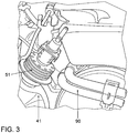
- ein Dosiermodul eines Reduktionskatalysators;
- Figur 4
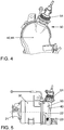
- den Reduktionskatalysator in Ansicht von der Seite;
- Figur 5
- den Oxidationskatalysator mit daran angeschlossenem Reduktionskatalysator in Ansicht von vorn;
- Figur 6
- den Oxidationskatalysator mit angeschlossenem Reduktionskatalysator in Schnittansicht;
- Figur 7
- eine erfindungsgemäße Abgasbehandlungseinrichtung mit integrierter Niederdruck-Abgasrückführungseinrichtung; und
- Figur 8
- ein Kraftfahrzeug in Ansicht von der Seite.
- In
Figur 1 ist deutlich ein Verbrennungsaggregat 10 ersichtlich, an dessen Abgasstrang 20 an einer Anschlusseinrichtung 21 ein Oxidationskatalysator 30 und an diesem stromabwärts in Abgas-Strömungsrichtung 23 im strich-punktierte angedeuteten Abgaspfad 22 ein Reduktionskatalysator 50 an einem verbindenden Modul 40 beziehungsweise an dessen Gehäuse 41 angeordnet ist. Das verbindende Modul 40 führt zu einem Partikelfilter 60, der ebenfalls im Abgaspfad 22 angeordnet ist. - Das heißt, dass der Reduktionskatalysator 50 am Gehäuse 41 des verbindenden Moduls 40 zwischen dem Oxidationskatalysator 30 und dem Partikelfilter 60 angeordnet ist.
- Entgegen herkömmlichen Ausführungsformen ist somit der Reduktionskatalysator 50 sehr dicht am Verbrennungsaggregat 10 beziehungsweise an der Anschlusseinrichtung 21 angeordnet, so dass Wärme des Abgases, welches aus der exothermen Reaktion im Verbrennungsaggregat 10 entsteht, genutzt wird, um den Reduktionskatalysator 50 auf die erforderliche Betriebstemperatur zu bringen beziehungsweise ihn auf dieser Temperatur zu halten. Dabei kann zusätzlich auch die Wärme im Reduktionskatalysator 50 genutzt werden, die bei einer exothermen Reaktion im Oxidationskatalysator 30 freigesetzt wird, da der Reduktionskatalysator 50 unmittelbar an den Oxidationskatalysator 30 anschließt.
- Wie
Figur 2 entnehmbar ist, ist vorzugsweise das Dosiermodul 51 des Reduktionskatalysators 50 an dem verbindenden Modul 40 beziehungsweise an dessen Gehäuse angeschlossen. - Wie in
Figur 3 erkennbar ist, ergeben sich trotz üblicher beengter Bauraumverhältnisse im Motorbereich keine Kollisionen mit weiteren Bauteilen, wie zum Beispiel mit der Sammelleitung 90. Die Erfindung ist vorzugsweise an einem quer einzubauenden beziehungsweise eingebauten Dieselmotor anzuwenden. - In den
Figuren 4 und 5 ist die zweckmäßige Ausgestaltung des Gehäuses 41 des verbindenden Moduls 40 gezeigt, um die Reduktion in diesem Modul 40 durchführen zu können. Ersichtlich ist, dass zur Realisierung der Reduktion im Wesentlichen lediglich das Dosiermodul 51 am verbindenden Modul 40 anzuordnen ist. - Aus
Figur 6 ist ersichtlich, in welchem Bereich die eigentliche Reduktion realisiert wird. Das Abgas strömt im Abgaspfad 22 entlang der Abgas-Strömungsrichtung 23 durch den Oxidationskatalysator 30 und von diesem in das Gehäuse 41. Das an diesem Gehäuse 41 angesetzte Dosiermodul 51 des Reduktionskatalysators 50 ermöglicht die Einbringung des Reduktionsmittels in das heiße Abgas zur Realisierung der Reduktion. Dabei erfolgt die Einbringung des Reduktionsmittels durch das Dosiermodul 51 bevorzugt durch eine Einspritzung 53, wie sie im Hohlraum des Gehäuses 41 angedeutet ist. Eine Kühlungseinheit 52 am Dosiermodul 51 kann dabei mit einer Kühleinrichtung des Verbrennungsaggregates 10 strömungstechnisch verbunden sein und/oder mit einer Kühleinrichtung einer Niederdruck-Abgasrückführungseinrichtung 70 verbunden sein. - Die Anordnung einer solchen Niederdruck-Abgasrückführungseinrichtung 70 ist
Figur 7 entnehmbar. Es ist ersichtlich, dass sich die Niederdruck-Abgasrückführungseinrichtung 70 im Abgaspfad 22 an den Partikelfilter 60 anschließt. Die Niederdruck-Abgasrückführungseinrichtung 70 weist dabei vorteilhafterweise eine Kühleinrichtung 80 auf, die, wie bereits beschrieben, mit der Kühlungseinheit 52 des Dosiermoduls 51 des Reduktionskatalysators 50 verbunden sein kann. Bei entsprechender Auslegung der Kühleinrichtung 80 des Verbrennungsaggregates 10 beziehungsweise der Niederdruck-Abgasrückführungseinrichtung 70 lässt sich das Dosiermodul 51 des Reduktionskatalysators 50 in einfacher und effizienter Weise kühlen, auch ohne Bauraum beanspruchende zusätzliche Kühlungsaggregate am Reduktionskatalysator 50 vorzusehen. - Aus
Figur 8 ist ersichtlich, dass der Reduktionskatalysator 50 vorzugsweise im Motorraum des Kraftfahrzeuges 100 anzuordnen ist, und zwar so dicht wie möglich am Verbrennungsaggregat 10. Das heißt, dass der Reduktionskatalysator 50 über dem Kraftfahrzeug-Unterboden 110 angeordnet ist. -
- 10
- Verbrennungsaggregat
- 20
- Abgasstrang
- 21
- Anschlusseinrichtung
- 22
- Abgaspfad
- 23
- Abgas-Strömungsrichtung
- 30
- Oxidationskatalysator
- 40
- verbindendes Modul
- 41
- Gehäuse
- 50
- Reduktionskatalysator
- 51
- Dosiermodul
- 52
- Kühlungseinheit
- 53
- Einspritzung
- 60
- Partikelfilter
- 70
- Niederdruck-Abgasrückführungseinrichtung
- 80
- Kühleinrichtung
- 90
- Sammelleitung
- 100
- Kraftfahrzeug
- 110
- Kraftfahrzeug-Unterboden
Claims (13)
- Abgasbehandlungseinrichtung zur Aufbereitung von Abgas eines Verbrennungsaggregats, umfassend einen Abgasstrang (20) und darin angeordnet einen Oxidationskatalysator (30), einen Reduktionskatalysator (50) zur selektiven katalytischen Reduktion und einen Partikelfilter (60), wobei der Oxidationskatalysator (30) stromaufwärts des Reduktionskatalysators (50) und der Reduktionskatalysator (50) stromaufwärts des Partikelfilters (60) angeordnet ist, wobei der Reduktionskatalysator (50) im Abgasstrang (20) in Abgas-Strömungsrichtung (23) derart weit stromaufwärts angeordnet ist, dass die Wärme des den Reduktionskatalysator (50) passierenden Abgases ausreicht, um den Reduktionskatalysator (50) auf Betriebstemperatur zu bringen, und der Reduktionskatalysator (50) ein Dosiermodul (51) zur dosierten Einbringung des Reduktionsmittels aufweist,dadurch gekennzeichnet, dass die Abgasbehandlungseinrichtung weiterhin eine Niederdruck-Abgasrückführungseinrichtung (70) aufweist, wobei die Niederdruck-Abgasrückführungseinrichtung (70) eine Kühleinrichtung (80) umfasst und das Dosiermodul (51) eine von einem Kühlmedium durchströmbare Kühlungseinheit (52) aufweist, wobei die Kühleinrichtung (80) derart wärmetechnisch mit dem Dosiermodul (51) des Reduktionskatalysators (50) verbunden ist, dass mittels der Kühleinrichtung (80) der Niederdruck-Abgasrückführungseinrichtung (70) das Dosiermodul (51) kühlbar ist, und die Kühlungseinheit (52) derart ausgestaltet und ausgelegt ist, dass die Kühlungseinheit (52) strömungstechnisch mit der Kühleinrichtung (80) der Niederdruck-Abgasrückführungseinrichtung (70) des Verbrennungsaggregats (10) verbindbar ist, so dass das Kühlmedium von der Kühleinrichtung (80) zur Kühlung des Dosiermoduls (51) nutzbar ist.
- Abgasbehandlungseinrichtung zur Aufbereitung von Abgas nach Anspruch 1, dadurch gekennzeichnet, dass der Reduktionskatalysator (50) derart weit stromaufwärts angeordnet ist, dass den Reduktionskatalysator (50) passierendes Abgas noch wenigstens 40 % der Temperatur aufweist, die das Abgas direkt nach der Verbrennung im Verbrennungsaggregat (10) hat.
- Abgasbehandlungseinrichtung zur Aufbereitung von Abgas nach einem der Ansprüche 1 und 2, dadurch gekennzeichnet, dass der Reduktionskatalysator (50) derart weit stromaufwärts angeordnet ist, dass den Reduktionskatalysator (50) passierendes Abgas noch wenigstens 80 % der Temperatur aufweist, die das Abgas direkt nach der Verbrennung im Verbrennungsaggregat (10) hat.
- Abgasbehandlungseinrichtung zur Aufbereitung von Abgas nach einem der vorhergehenden Ansprüche, dadurch gekennzeichnet, dass die Abgasbehandlungseinrichtung eine Abgasbehandlungseinrichtung eines Dieselmotors ist.
- Abgasbehandlungseinrichtung zur Aufbereitung von Abgas nach einem der Ansprüche 1 bis 4, dadurch gekennzeichnet, dass der Reduktionskatalysator (50) an einem den Oxidationskatalysator (30) mit dem Partikelfilter (60) verbindenden Modul (40) angeordnet ist.
- Abgasbehandlungseinrichtung zur Aufbereitung von Abgas nach Anspruch 5, dadurch gekennzeichnet, dass das Modul (40) ein von Abgas durchströmbares Gehäuse (41) aufweist, welches als Gehäuse (41) des Reduktionskatalysators (50) dient.
- Abgasbehandlungseinrichtung zur Aufbereitung von Abgas nach einem der Ansprüche 1 bis 4, dadurch gekennzeichnet, dass der Reduktionskatalysator (50) am Partikelfilter (60) angeordnet ist.
- Verfahren zur Aufbereitung von Abgas eines Verbrennungsaggregats durch selektive katalytische Reduktion mittels eines durch ein Dosiermodul (51) dosiert eingebrachtem Reduktionsmittels, welches durch einen mit dem Verbrennungsaggregat (10) gekoppelten Abgasstrang (20) strömt, wobei in dem Abgasstrang (20) ein Oxidationskatalysator (30) stromaufwärts eines zur selektiven katalytischen Reduktion vorgesehenen Reduktionskatalysators (50), der Reduktionskatalysator (50) stromaufwärts eines Partikelfilters (60) angeordnet ist, und Wärme des den Reduktionskatalysator (50) passierenden Abgases genutzt wird, um den Reduktionskatalysator (50) auf Betriebstemperatur zu erwärmen, dadurch gekennzeichnet, dass mittels einer Niederdruck-Abgasrückführungseinrichtung (70), welche eine Kühleinrichtung (80) umfasst, die derart wärmetechnisch mit dem Dosiermodul (51) des Reduktionskatalysators (50) verbunden ist, dass mittels der Kühleinrichtung (80) der Niederdruck-Abgasrückführungseinrichtung (70) das Dosiermodul (51) kühlbar ist, das Dosiermodul (51) mit Kühlmedium der Kühleinrichtung (80) gekühlt wird.
- Verfahren zur Aufbereitung von Abgas nach Anspruch 8, dadurch gekennzeichnet, dass ausschließlich Wärme des den Reduktionskatalysator passierenden Abgases genutzt wird, um den Reduktionskatalysator auf Betriebstemperatur zu bringen.
- Verfahren zur Aufbereitung von Abgas nach einem der Ansprüche 8 und 9, dadurch gekennzeichnet, dass das Reduktionsmittel direkt in den Partikelfilter oder in ein Modul eingespritzt wird, welches den Oxidationskatalysator mit dem Partikelfilter strömungstechnisch verbindet.
- Kraftfahrzeug mit einer Abgasbehandlungseinrichtung nach einem der Ansprüche 1 bis 7.
- Kraftfahrzeug nach Anspruch 11, dadurch gekennzeichnet, dass das Kraftfahrzeug dieselmotorisch betrieben ist.
- Kraftfahrzeug nach einem der Ansprüche 11 und 12, dadurch gekennzeichnet, dass der Reduktionskatalysator (50) oberhalb des Kraftfahrzeug-Unterbodens (110) angeordnet ist.
Priority Applications (1)
| Application Number | Priority Date | Filing Date | Title |
|---|---|---|---|
| EP17155494.2A EP3181850B1 (de) | 2011-08-25 | 2012-08-08 | Abgasbehandlungseinrichtung, verfahren zur aufbereitung von abgas und kraftfahrzeug |
Applications Claiming Priority (2)
| Application Number | Priority Date | Filing Date | Title |
|---|---|---|---|
| DE102011111590A DE102011111590A1 (de) | 2011-08-25 | 2011-08-25 | Abgasbehandlungseinrichtung, Verfahren zur Aufbereitung von Abgas und Kraftfahrzeug |
| PCT/EP2012/003387 WO2013026533A2 (de) | 2011-08-25 | 2012-08-08 | Abgasbehandlungseinrichtung, verfahren zur aufbereitung von abgas und kraftfahrzeug |
Related Child Applications (2)
| Application Number | Title | Priority Date | Filing Date |
|---|---|---|---|
| EP17155494.2A Division EP3181850B1 (de) | 2011-08-25 | 2012-08-08 | Abgasbehandlungseinrichtung, verfahren zur aufbereitung von abgas und kraftfahrzeug |
| EP17155494.2A Division-Into EP3181850B1 (de) | 2011-08-25 | 2012-08-08 | Abgasbehandlungseinrichtung, verfahren zur aufbereitung von abgas und kraftfahrzeug |
Publications (2)
| Publication Number | Publication Date |
|---|---|
| EP2748440A2 EP2748440A2 (de) | 2014-07-02 |
| EP2748440B1 true EP2748440B1 (de) | 2017-03-22 |
Family
ID=46690468
Family Applications (2)
| Application Number | Title | Priority Date | Filing Date |
|---|---|---|---|
| EP17155494.2A Active EP3181850B1 (de) | 2011-08-25 | 2012-08-08 | Abgasbehandlungseinrichtung, verfahren zur aufbereitung von abgas und kraftfahrzeug |
| EP12748167.9A Active EP2748440B1 (de) | 2011-08-25 | 2012-08-08 | Abgasbehandlungseinrichtung, verfahren zur aufbereitung von abgas und kraftfahrzeug |
Family Applications Before (1)
| Application Number | Title | Priority Date | Filing Date |
|---|---|---|---|
| EP17155494.2A Active EP3181850B1 (de) | 2011-08-25 | 2012-08-08 | Abgasbehandlungseinrichtung, verfahren zur aufbereitung von abgas und kraftfahrzeug |
Country Status (5)
| Country | Link |
|---|---|
| US (1) | US9562454B2 (de) |
| EP (2) | EP3181850B1 (de) |
| CN (1) | CN103748332B (de) |
| DE (1) | DE102011111590A1 (de) |
| WO (1) | WO2013026533A2 (de) |
Families Citing this family (12)
| Publication number | Priority date | Publication date | Assignee | Title |
|---|---|---|---|---|
| JP6163447B2 (ja) * | 2013-09-26 | 2017-07-12 | 株式会社クボタ | エンジン |
| JP1533877S (de) * | 2013-12-20 | 2015-09-28 | ||
| DE102014211159A1 (de) | 2014-06-11 | 2015-12-17 | Volkswagen Aktiengesellschaft | Vorrichtung zur katalytischen chemischen Umsetzungwenigstens einer Komponente eines Gasstromsund Abgasanlage für eine Brennkraftmaschine |
| DE102014221322A1 (de) | 2014-10-21 | 2016-04-21 | Volkswagen Aktiengesellschaft | Abgasbehandlungseinrichtung für eine Abgasanlage einer Brennkraftmaschine |
| FR3029969A1 (fr) * | 2014-12-10 | 2016-06-17 | Peugeot Citroen Automobiles Sa | Dispositif de post-traitement des gaz d’echappement d’un moteur a combustion |
| USD750137S1 (en) * | 2014-12-10 | 2016-02-23 | Msd Llc | Ignition coil cover system |
| FR3037615B1 (fr) * | 2015-06-17 | 2019-08-23 | Renault S.A.S | Systeme de depollution des gaz d'echappement optimise |
| JP7102747B2 (ja) * | 2018-01-25 | 2022-07-20 | マツダ株式会社 | エンジンの排気浄化装置 |
| JP7087722B2 (ja) * | 2018-06-26 | 2022-06-21 | マツダ株式会社 | エンジンの排気装置 |
| JP2020012433A (ja) | 2018-07-19 | 2020-01-23 | いすゞ自動車株式会社 | 車載エンジンの排気構造 |
| DE102019101487A1 (de) | 2019-01-22 | 2020-07-23 | Volkswagen Aktiengesellschaft | Anordnung von mindestens zwei motornahen Abgasanlagenkomponenten für eine Brennkraftmaschine eines Kraftfahrzeugs sowie Kraftfahrzeug |
| JP2019082181A (ja) * | 2019-02-28 | 2019-05-30 | マツダ株式会社 | エンジンの排気装置 |
Citations (2)
| Publication number | Priority date | Publication date | Assignee | Title |
|---|---|---|---|---|
| EP2105592A1 (de) * | 2008-03-28 | 2009-09-30 | Magneti Marelli Powertrain S.p.A. | Haltevorrichtung für einen Injektor in einem Abgassystem einer Brennkraftmaschine |
| DE102009027185A1 (de) * | 2009-06-25 | 2010-12-30 | Robert Bosch Gmbh | Dosiervorrichtung zur Nachbehandlung von Abgasen |
Family Cites Families (63)
| Publication number | Priority date | Publication date | Assignee | Title |
|---|---|---|---|---|
| FR1050453A (fr) | 1950-11-22 | 1954-01-07 | Westinghouse Electric Corp | Dépoussiéreurs électrostatiques |
| US3565830A (en) | 1963-02-07 | 1971-02-23 | Engelhard Min & Chem | Coated film of catalytically active oxide on a refractory support |
| US4335023A (en) | 1980-01-24 | 1982-06-15 | Engelhard Corporation | Monolithic catalyst member and support therefor |
| DE4007516C2 (de) | 1990-03-09 | 1997-03-06 | Kloeckner Humboldt Deutz Ag | Dieselmotor |
| DE59710811D1 (de) | 1997-07-28 | 2003-11-06 | Siemens Ag | Verwendung eines statischer Mischers als Hydrilysekatalysator sowie dessen Verwendung in einer Abgasleitung für eine Verbrennungsanlage |
| FR2810072B1 (fr) | 2000-06-08 | 2004-07-16 | Peugeot Citroen Automobiles Sa | Vehicule automobile comportant un filtre a particules a l'interieur du compartiment moteur et procede et installation de nettoyage du filtre a particules |
| FR2810075B1 (fr) | 2000-06-08 | 2005-08-12 | Peugeot Citroen Automobiles Sa | Vehicule automobile a moteur thermique comportant une ligne d'echappement ayant un systeme de depollution place a l'avant du moteur |
| DE10155675A1 (de) * | 2001-08-18 | 2003-05-28 | Bosch Gmbh Robert | Verfahren und Vorrichtung zur Speicherung und Dosierung eines Reduktionsmittels |
| US6722123B2 (en) | 2001-10-17 | 2004-04-20 | Fleetguard, Inc. | Exhaust aftertreatment device, including chemical mixing and acoustic effects |
| GB2381218B (en) | 2001-10-25 | 2004-12-15 | Eminox Ltd | Gas treatment apparatus |
| DE10250050A1 (de) | 2002-10-25 | 2004-05-06 | Purem Abgassysteme Gmbh & Co. Kg | Abgasnachbehandlungssystem, insbesondere für einen Dieselmotor |
| US6928806B2 (en) * | 2002-11-21 | 2005-08-16 | Ford Global Technologies, Llc | Exhaust gas aftertreatment systems |
| US6823663B2 (en) * | 2002-11-21 | 2004-11-30 | Ford Global Technologies, Llc | Exhaust gas aftertreatment systems |
| DE10300298A1 (de) * | 2003-01-02 | 2004-07-15 | Daimlerchrysler Ag | Abgasnachbehandlungseinrichtung und -verfahren |
| DE10323607B4 (de) | 2003-05-20 | 2019-05-09 | Robert Bosch Gmbh | Vorrichtung zur Reinigung von Abgasen eines Verbrennungsmotors |
| US7229597B2 (en) | 2003-08-05 | 2007-06-12 | Basfd Catalysts Llc | Catalyzed SCR filter and emission treatment system |
| JP2005155404A (ja) | 2003-11-25 | 2005-06-16 | Komatsu Ltd | 内燃機関の排気ガス浄化装置 |
| DE102004046879A1 (de) * | 2004-09-28 | 2006-04-13 | Robert Bosch Gmbh | Dosiervorrichtung und Brennkraftmaschine mit Dosiervorrichtung |
| CN100554657C (zh) | 2004-11-25 | 2009-10-28 | 株式会社小松制作所 | 内燃机的废气净化装置 |
| US7263824B2 (en) | 2004-12-03 | 2007-09-04 | Cummins, Inc. | Exhaust gas aftertreatment device for an internal combustion engine |
| DE102005039630B4 (de) | 2005-08-20 | 2007-08-02 | Technische Universität Kaiserslautern | Vorrichtung, Reaktor und Verfahren zur Reduzierung von Stickoxyden im Abgasstrom von Verbrennungskraftmaschinen |
| US7367188B2 (en) * | 2006-07-28 | 2008-05-06 | Ford Global Technologies, Llc | System and method for diagnostic of low pressure exhaust gas recirculation system and adapting of measurement devices |
| KR20070033599A (ko) * | 2005-09-22 | 2007-03-27 | 현대자동차주식회사 | Src시스템의 요소를 이용한 egr 쿨링시스템 |
| JP4698359B2 (ja) | 2005-09-22 | 2011-06-08 | Udトラックス株式会社 | 排気浄化装置 |
| JP4785766B2 (ja) | 2007-02-09 | 2011-10-05 | 日野自動車株式会社 | 排気浄化装置 |
| JP4886547B2 (ja) | 2007-02-23 | 2012-02-29 | 日野自動車株式会社 | 排気浄化装置 |
| US20080202101A1 (en) * | 2007-02-23 | 2008-08-28 | Driscoll James J | Exhaust treatment system |
| DE102007011184A1 (de) | 2007-03-06 | 2008-09-11 | Behr Gmbh & Co. Kg | Wärmetauscher zur Kühlung von Abgas, Vorrichtung zur Überführung einer flüssigen Harnstofflösung in zumindest gasförmiges Ammoniak, System zur Abgaskühlung, Verfahren zur Rückführung von Abgas und zur Stickoxidreduzierung |
| JP4943499B2 (ja) | 2007-03-12 | 2012-05-30 | ボッシュ株式会社 | 内燃機関の排気浄化装置 |
| JP4737644B2 (ja) * | 2007-06-20 | 2011-08-03 | 株式会社デンソー | 内燃機関の排気浄化装置 |
| JP5173308B2 (ja) * | 2007-07-31 | 2013-04-03 | 日野自動車株式会社 | 排気浄化装置 |
| JP5099684B2 (ja) | 2007-08-06 | 2012-12-19 | ボッシュ株式会社 | 排気浄化装置 |
| JP2009097479A (ja) * | 2007-10-19 | 2009-05-07 | Bosch Corp | 還元剤供給装置の制御装置及び制御方法 |
| JP5044359B2 (ja) | 2007-10-23 | 2012-10-10 | 三菱ふそうトラック・バス株式会社 | エンジンの排気浄化装置 |
| JP2009103093A (ja) | 2007-10-25 | 2009-05-14 | Mitsubishi Fuso Truck & Bus Corp | ディーゼルエンジンの制御装置 |
| DE102007056202A1 (de) | 2007-11-22 | 2009-05-28 | Audi Ag | Abgasnachbehandlungseinrichtung für eine Brennkraftmaschine und Verfahren zur Nachbehandlung von Abgasen einer Brennkraftmaschine |
| KR100892525B1 (ko) * | 2007-12-14 | 2009-04-10 | 현대자동차주식회사 | 요소탱크를 이용한 자동변속기 오일 냉각 장치 |
| JP2009156077A (ja) * | 2007-12-25 | 2009-07-16 | Mitsubishi Motors Corp | 内燃機関の排気ガス浄化装置 |
| JP5114219B2 (ja) * | 2008-01-10 | 2013-01-09 | 東京濾器株式会社 | 内燃機関用の排ガス浄化装置 |
| US8151558B2 (en) * | 2008-01-31 | 2012-04-10 | Caterpillar Inc. | Exhaust system implementing SCR and EGR |
| US8381512B2 (en) | 2008-05-02 | 2013-02-26 | GM Global Technology Operations LLC | Passive ammonia-selective catalytic reduction for NOx control in internal combustion engines |
| JP5256881B2 (ja) | 2008-06-25 | 2013-08-07 | いすゞ自動車株式会社 | 排気ガス浄化装置 |
| US8475752B2 (en) | 2008-06-27 | 2013-07-02 | Basf Corporation | NOx adsorber catalyst with superior low temperature performance |
| JP5308176B2 (ja) | 2009-02-03 | 2013-10-09 | ヤンマー株式会社 | 排気浄化装置 |
| DE102009007765A1 (de) | 2009-02-06 | 2010-08-12 | Daimler Ag | Verfahren zum Betreiben einer Brennkraftmaschine mit einer einen SCR-Katalysator umfassenden Abgasreinigungsanlage |
| FR2943383B1 (fr) | 2009-03-23 | 2011-03-25 | Renault Sas | Circuit d'alimentation et d'echappement de vehicule automobile |
| FR2947003B1 (fr) | 2009-06-19 | 2015-04-10 | Faurecia Sys Echappement | Ligne d'echappement avec systeme d'injection |
| US9056802B2 (en) | 2009-07-31 | 2015-06-16 | General Electric Company | Methods for making environmental barrier coatings using sintering aids |
| DE102009043085A1 (de) | 2009-09-25 | 2011-08-04 | Volkswagen AG, 38440 | Brennkraftmaschine mit einem Abgasturbolader und einem Abgasrückführsystem |
| FR2953737B1 (fr) * | 2009-12-11 | 2013-03-15 | Inst Francais Du Petrole | Procede de traitement de polluants contenus dans des gaz d'echappement, notamment d'un moteur a combustion interne, et installation utilisant un tel procede |
| EP2354485A1 (de) * | 2010-01-13 | 2011-08-10 | Delphi Technologies Holding S.à.r.l. | Abgassystem für eine Maschine mit Kompressionszündung |
| FR2955612B1 (fr) * | 2010-01-25 | 2016-02-12 | Peugeot Citroen Automobiles Sa | Dispositif de post-traitement des gaz d'echappement d'un moteur a combustion |
| JP6000506B2 (ja) * | 2010-03-24 | 2016-09-28 | 日野自動車株式会社 | 排気浄化装置 |
| US8276366B2 (en) | 2010-03-30 | 2012-10-02 | GM Global Technology Operations LLC | Closely coupled exhaust aftertreatment system for an internal combustion engine having twin turbochargers |
| US20120124983A1 (en) * | 2010-11-23 | 2012-05-24 | Haiping Hong | Exhaust system having reductant nozzle flow diverter |
| FR2971810B1 (fr) * | 2011-02-18 | 2013-03-15 | Peugeot Citroen Automobiles Sa | Ensemble de post-traitement des gaz d'echappement d'un moteur a combustion suralimente, et vehicule automobile comportant un tel ensemble |
| WO2012114187A2 (en) * | 2011-02-21 | 2012-08-30 | Johnson Matthey Public Limited Company | Exhaust system including nox reduction catalyst and egr circuit |
| FR2972764B1 (fr) | 2011-03-16 | 2013-03-29 | Peugeot Citroen Automobiles Sa | Ensemble compact coude de post-traitement de gaz d'echappement dote d'un bossage formant melangeur de reducteur scr |
| FR2975129B1 (fr) | 2011-05-09 | 2013-05-17 | Peugeot Citroen Automobiles Sa | Systeme comportant un moteur a combustion, un ensemble en " u " de traitement des gaz d'echappement, et un ecran thermique optimise |
| DE102011101079B4 (de) * | 2011-05-10 | 2020-08-20 | Umicore Ag & Co. Kg | Verfahren zur Regeneration von NOx-Speicherkatalysatoren von Dieselmotoren mit Niederdruck-AGR |
| DE102011107692B3 (de) * | 2011-07-13 | 2013-01-03 | Umicore Ag & Co. Kg | Verfahren zur Reaktivierung von Abgasreinigungsanlagen von Dieselmotoren mit Niederdruck-AGR |
| FR2978492B1 (fr) | 2011-07-28 | 2013-08-02 | Peugeot Citroen Automobiles Sa | Ensemble coude de post-traitement des gaz d'echappement d'un moteur a combustion comportant un convergent interne |
| GB2525721B (en) * | 2014-02-27 | 2016-12-28 | Johnson Matthey Plc | Exhaust system having N20 catalyst in EGR circuit |
-
2011
- 2011-08-25 DE DE102011111590A patent/DE102011111590A1/de not_active Withdrawn
-
2012
- 2012-08-08 EP EP17155494.2A patent/EP3181850B1/de active Active
- 2012-08-08 WO PCT/EP2012/003387 patent/WO2013026533A2/de active Application Filing
- 2012-08-08 CN CN201280041448.7A patent/CN103748332B/zh active Active
- 2012-08-08 US US14/240,772 patent/US9562454B2/en active Active
- 2012-08-08 EP EP12748167.9A patent/EP2748440B1/de active Active
Patent Citations (2)
| Publication number | Priority date | Publication date | Assignee | Title |
|---|---|---|---|---|
| EP2105592A1 (de) * | 2008-03-28 | 2009-09-30 | Magneti Marelli Powertrain S.p.A. | Haltevorrichtung für einen Injektor in einem Abgassystem einer Brennkraftmaschine |
| DE102009027185A1 (de) * | 2009-06-25 | 2010-12-30 | Robert Bosch Gmbh | Dosiervorrichtung zur Nachbehandlung von Abgasen |
Also Published As
| Publication number | Publication date |
|---|---|
| EP3181850B1 (de) | 2019-10-09 |
| EP3181850A1 (de) | 2017-06-21 |
| DE102011111590A1 (de) | 2013-02-28 |
| CN103748332B (zh) | 2017-06-09 |
| US9562454B2 (en) | 2017-02-07 |
| CN103748332A (zh) | 2014-04-23 |
| US20140202136A1 (en) | 2014-07-24 |
| WO2013026533A2 (de) | 2013-02-28 |
| WO2013026533A3 (de) | 2013-04-11 |
| EP2748440A2 (de) | 2014-07-02 |
Similar Documents
| Publication | Publication Date | Title |
|---|---|---|
| EP2748440B1 (de) | Abgasbehandlungseinrichtung, verfahren zur aufbereitung von abgas und kraftfahrzeug | |
| EP3418518B1 (de) | Abgasnachbehandlungssystem und verfahren zur abgasnachbehandlung eines verbrennungsmotors | |
| EP2907564B1 (de) | Verfahren zur reinigung von dieselmotorenabgasen | |
| EP3660287B1 (de) | Abgasnachbehandlungssystem sowie verfahren zur abgasnachbehandlung eines verbrennungsmotors | |
| EP2907984B1 (de) | Brennkraftmaschine | |
| EP1977090B1 (de) | Vorrichtung zur reduktion von stickoxiden im abgas von brennkraftmaschinen | |
| DE102007042836B4 (de) | Vorrichtung zur Abgasnachbehandlung eines Abgasstroms eines Kraftfahrzeuges | |
| DE202012011764U1 (de) | Mischer zur Nachbehandlung von Abgasen | |
| DE102014019427A1 (de) | Verfahren zur Reinigung von Dieselmotorenabgasen | |
| EP2107223B1 (de) | Brennkraftmaschine mit einem Abgassystem, dem mittels einer Dosiereinheit ein Zusatzstoff zudosierbar ist | |
| EP3385520B1 (de) | Abgasnachbehandlungsvorrichtung für einen verbrennungsmotor | |
| DE102018220121A1 (de) | Abgasnachbehandlungssystem und Verfahren zur Abgasnachbehandlung eines Verbrennungsmotors | |
| DE102019119123B4 (de) | Verfahren zum Aufheizen eines Abgasnachbehandlungssystems sowie Abgasnachbehandlungssystem | |
| DE102006043104A1 (de) | Abgasreinigungsanlage für ein Kraftfahrzeug | |
| DE102020100529A1 (de) | Verbrennungsmotor sowie Verfahren zum Aufheizen einer Abgasanlage eines solchen Verbrennungsmotors | |
| AT524011B1 (de) | Kraftfahrzeug mit einem mit kohlenstofffreiem Kraftstoff betriebenen Verbrennungsmotor mit daran angeschlossenem Abgassystem | |
| DE102008006630A1 (de) | Vorrichtung zur Abgasnachbehandlung eines Abgasstroms eines Kraftfahrzeuges | |
| DE102018132833A1 (de) | Verfahren zur Abgasnachbehandlung eines Verbrennungsmotors sowie Abgasnachbehandlungssystem | |
| DE102018220570A1 (de) | Kompakt bauendes Abgasnachbehandlungssystem | |
| EP4036386A1 (de) | Verbrennungskraftmaschine für ein kraftfahrzeug, insbesondere für einen kraftwagen, sowie kraftfahrzeug, insbesondere kraftwagen | |
| EP3751106B1 (de) | Abgasnachbehandlungssystem und verfahren zur abgasnachbehandlung eines verbrennungsmotors | |
| DE102007038410B4 (de) | Vorrichtung und Verfahren zur selektiven katalytischen Reduktion von Stickoxiden in einem sauerstoffhaltigen Abgas einer Verbrennungsanlage | |
| DE102012006365A1 (de) | Abgasanlage für ein Fahrzeug | |
| DE102019123453A1 (de) | Abgasnachbehandlungssystem und Verfahren zum Temperaturmanagement eines SCR-Katalysators in der Abgasanlage eines Verbrennungsmotors | |
| DE102019115155A1 (de) | Abgasnachbehandlungssystem sowie Verfahren zur Abgasnachbehandlung eines Verbrennungsmotors |
Legal Events
| Date | Code | Title | Description |
|---|---|---|---|
| PUAI | Public reference made under article 153(3) epc to a published international application that has entered the european phase |
Free format text: ORIGINAL CODE: 0009012 |
|
| 17P | Request for examination filed |
Effective date: 20140325 |
|
| AK | Designated contracting states |
Kind code of ref document: A2 Designated state(s): AL AT BE BG CH CY CZ DE DK EE ES FI FR GB GR HR HU IE IS IT LI LT LU LV MC MK MT NL NO PL PT RO RS SE SI SK SM TR |
|
| DAX | Request for extension of the european patent (deleted) | ||
| 17Q | First examination report despatched |
Effective date: 20160204 |
|
| REG | Reference to a national code |
Ref country code: DE Ref legal event code: R079 Ref document number: 502012009861 Country of ref document: DE Free format text: PREVIOUS MAIN CLASS: F01N0013020000 Ipc: F01N0003100000 |
|
| RIC1 | Information provided on ipc code assigned before grant |
Ipc: F01N 3/035 20060101ALI20160929BHEP Ipc: F01N 13/00 20100101ALI20160929BHEP Ipc: F01N 3/20 20060101ALI20160929BHEP Ipc: F02M 26/30 20160101ALI20160929BHEP Ipc: F01N 3/10 20060101AFI20160929BHEP Ipc: F02M 26/15 20160101ALI20160929BHEP |
|
| GRAP | Despatch of communication of intention to grant a patent |
Free format text: ORIGINAL CODE: EPIDOSNIGR1 |
|
| INTG | Intention to grant announced |
Effective date: 20161110 |
|
| GRAS | Grant fee paid |
Free format text: ORIGINAL CODE: EPIDOSNIGR3 |
|
| GRAA | (expected) grant |
Free format text: ORIGINAL CODE: 0009210 |
|
| AK | Designated contracting states |
Kind code of ref document: B1 Designated state(s): AL AT BE BG CH CY CZ DE DK EE ES FI FR GB GR HR HU IE IS IT LI LT LU LV MC MK MT NL NO PL PT RO RS SE SI SK SM TR |
|
| REG | Reference to a national code |
Ref country code: GB Ref legal event code: FG4D Free format text: NOT ENGLISH |
|
| REG | Reference to a national code |
Ref country code: CH Ref legal event code: EP |
|
| REG | Reference to a national code |
Ref country code: AT Ref legal event code: REF Ref document number: 878021 Country of ref document: AT Kind code of ref document: T Effective date: 20170415 |
|
| REG | Reference to a national code |
Ref country code: IE Ref legal event code: FG4D Free format text: LANGUAGE OF EP DOCUMENT: GERMAN |
|
| REG | Reference to a national code |
Ref country code: DE Ref legal event code: R096 Ref document number: 502012009861 Country of ref document: DE |
|
| REG | Reference to a national code |
Ref country code: NL Ref legal event code: MP Effective date: 20170322 |
|
| PG25 | Lapsed in a contracting state [announced via postgrant information from national office to epo] |
Ref country code: NO Free format text: LAPSE BECAUSE OF FAILURE TO SUBMIT A TRANSLATION OF THE DESCRIPTION OR TO PAY THE FEE WITHIN THE PRESCRIBED TIME-LIMIT Effective date: 20170622 Ref country code: HR Free format text: LAPSE BECAUSE OF FAILURE TO SUBMIT A TRANSLATION OF THE DESCRIPTION OR TO PAY THE FEE WITHIN THE PRESCRIBED TIME-LIMIT Effective date: 20170322 Ref country code: GR Free format text: LAPSE BECAUSE OF FAILURE TO SUBMIT A TRANSLATION OF THE DESCRIPTION OR TO PAY THE FEE WITHIN THE PRESCRIBED TIME-LIMIT Effective date: 20170623 Ref country code: LT Free format text: LAPSE BECAUSE OF FAILURE TO SUBMIT A TRANSLATION OF THE DESCRIPTION OR TO PAY THE FEE WITHIN THE PRESCRIBED TIME-LIMIT Effective date: 20170322 Ref country code: FI Free format text: LAPSE BECAUSE OF FAILURE TO SUBMIT A TRANSLATION OF THE DESCRIPTION OR TO PAY THE FEE WITHIN THE PRESCRIBED TIME-LIMIT Effective date: 20170322 |
|
| REG | Reference to a national code |
Ref country code: LT Ref legal event code: MG4D |
|
| REG | Reference to a national code |
Ref country code: FR Ref legal event code: PLFP Year of fee payment: 6 |
|
| PG25 | Lapsed in a contracting state [announced via postgrant information from national office to epo] |
Ref country code: LV Free format text: LAPSE BECAUSE OF FAILURE TO SUBMIT A TRANSLATION OF THE DESCRIPTION OR TO PAY THE FEE WITHIN THE PRESCRIBED TIME-LIMIT Effective date: 20170322 Ref country code: RS Free format text: LAPSE BECAUSE OF FAILURE TO SUBMIT A TRANSLATION OF THE DESCRIPTION OR TO PAY THE FEE WITHIN THE PRESCRIBED TIME-LIMIT Effective date: 20170322 Ref country code: SE Free format text: LAPSE BECAUSE OF FAILURE TO SUBMIT A TRANSLATION OF THE DESCRIPTION OR TO PAY THE FEE WITHIN THE PRESCRIBED TIME-LIMIT Effective date: 20170322 Ref country code: BG Free format text: LAPSE BECAUSE OF FAILURE TO SUBMIT A TRANSLATION OF THE DESCRIPTION OR TO PAY THE FEE WITHIN THE PRESCRIBED TIME-LIMIT Effective date: 20170622 |
|
| PG25 | Lapsed in a contracting state [announced via postgrant information from national office to epo] |
Ref country code: NL Free format text: LAPSE BECAUSE OF FAILURE TO SUBMIT A TRANSLATION OF THE DESCRIPTION OR TO PAY THE FEE WITHIN THE PRESCRIBED TIME-LIMIT Effective date: 20170322 |
|
| PG25 | Lapsed in a contracting state [announced via postgrant information from national office to epo] |
Ref country code: CZ Free format text: LAPSE BECAUSE OF FAILURE TO SUBMIT A TRANSLATION OF THE DESCRIPTION OR TO PAY THE FEE WITHIN THE PRESCRIBED TIME-LIMIT Effective date: 20170322 Ref country code: ES Free format text: LAPSE BECAUSE OF FAILURE TO SUBMIT A TRANSLATION OF THE DESCRIPTION OR TO PAY THE FEE WITHIN THE PRESCRIBED TIME-LIMIT Effective date: 20170322 Ref country code: RO Free format text: LAPSE BECAUSE OF FAILURE TO SUBMIT A TRANSLATION OF THE DESCRIPTION OR TO PAY THE FEE WITHIN THE PRESCRIBED TIME-LIMIT Effective date: 20170322 Ref country code: SK Free format text: LAPSE BECAUSE OF FAILURE TO SUBMIT A TRANSLATION OF THE DESCRIPTION OR TO PAY THE FEE WITHIN THE PRESCRIBED TIME-LIMIT Effective date: 20170322 Ref country code: IT Free format text: LAPSE BECAUSE OF FAILURE TO SUBMIT A TRANSLATION OF THE DESCRIPTION OR TO PAY THE FEE WITHIN THE PRESCRIBED TIME-LIMIT Effective date: 20170322 Ref country code: EE Free format text: LAPSE BECAUSE OF FAILURE TO SUBMIT A TRANSLATION OF THE DESCRIPTION OR TO PAY THE FEE WITHIN THE PRESCRIBED TIME-LIMIT Effective date: 20170322 |
|
| PG25 | Lapsed in a contracting state [announced via postgrant information from national office to epo] |
Ref country code: PT Free format text: LAPSE BECAUSE OF FAILURE TO SUBMIT A TRANSLATION OF THE DESCRIPTION OR TO PAY THE FEE WITHIN THE PRESCRIBED TIME-LIMIT Effective date: 20170724 Ref country code: SM Free format text: LAPSE BECAUSE OF FAILURE TO SUBMIT A TRANSLATION OF THE DESCRIPTION OR TO PAY THE FEE WITHIN THE PRESCRIBED TIME-LIMIT Effective date: 20170322 Ref country code: PL Free format text: LAPSE BECAUSE OF FAILURE TO SUBMIT A TRANSLATION OF THE DESCRIPTION OR TO PAY THE FEE WITHIN THE PRESCRIBED TIME-LIMIT Effective date: 20170322 Ref country code: IS Free format text: LAPSE BECAUSE OF FAILURE TO SUBMIT A TRANSLATION OF THE DESCRIPTION OR TO PAY THE FEE WITHIN THE PRESCRIBED TIME-LIMIT Effective date: 20170722 |
|
| REG | Reference to a national code |
Ref country code: DE Ref legal event code: R097 Ref document number: 502012009861 Country of ref document: DE |
|
| PLBE | No opposition filed within time limit |
Free format text: ORIGINAL CODE: 0009261 |
|
| STAA | Information on the status of an ep patent application or granted ep patent |
Free format text: STATUS: NO OPPOSITION FILED WITHIN TIME LIMIT |
|
| PG25 | Lapsed in a contracting state [announced via postgrant information from national office to epo] |
Ref country code: DK Free format text: LAPSE BECAUSE OF FAILURE TO SUBMIT A TRANSLATION OF THE DESCRIPTION OR TO PAY THE FEE WITHIN THE PRESCRIBED TIME-LIMIT Effective date: 20170322 |
|
| 26N | No opposition filed |
Effective date: 20180102 |
|
| PG25 | Lapsed in a contracting state [announced via postgrant information from national office to epo] |
Ref country code: SI Free format text: LAPSE BECAUSE OF FAILURE TO SUBMIT A TRANSLATION OF THE DESCRIPTION OR TO PAY THE FEE WITHIN THE PRESCRIBED TIME-LIMIT Effective date: 20170322 |
|
| REG | Reference to a national code |
Ref country code: CH Ref legal event code: PL |
|
| PG25 | Lapsed in a contracting state [announced via postgrant information from national office to epo] |
Ref country code: MC Free format text: LAPSE BECAUSE OF FAILURE TO SUBMIT A TRANSLATION OF THE DESCRIPTION OR TO PAY THE FEE WITHIN THE PRESCRIBED TIME-LIMIT Effective date: 20170322 |
|
| PG25 | Lapsed in a contracting state [announced via postgrant information from national office to epo] |
Ref country code: LI Free format text: LAPSE BECAUSE OF NON-PAYMENT OF DUE FEES Effective date: 20170831 Ref country code: CH Free format text: LAPSE BECAUSE OF NON-PAYMENT OF DUE FEES Effective date: 20170831 |
|
| REG | Reference to a national code |
Ref country code: IE Ref legal event code: MM4A |
|
| REG | Reference to a national code |
Ref country code: BE Ref legal event code: MM Effective date: 20170831 |
|
| PG25 | Lapsed in a contracting state [announced via postgrant information from national office to epo] |
Ref country code: LU Free format text: LAPSE BECAUSE OF NON-PAYMENT OF DUE FEES Effective date: 20170808 |
|
| PG25 | Lapsed in a contracting state [announced via postgrant information from national office to epo] |
Ref country code: IE Free format text: LAPSE BECAUSE OF NON-PAYMENT OF DUE FEES Effective date: 20170808 |
|
| REG | Reference to a national code |
Ref country code: FR Ref legal event code: PLFP Year of fee payment: 7 |
|
| PG25 | Lapsed in a contracting state [announced via postgrant information from national office to epo] |
Ref country code: BE Free format text: LAPSE BECAUSE OF NON-PAYMENT OF DUE FEES Effective date: 20170831 |
|
| PG25 | Lapsed in a contracting state [announced via postgrant information from national office to epo] |
Ref country code: MT Free format text: LAPSE BECAUSE OF FAILURE TO SUBMIT A TRANSLATION OF THE DESCRIPTION OR TO PAY THE FEE WITHIN THE PRESCRIBED TIME-LIMIT Effective date: 20170322 |
|
| REG | Reference to a national code |
Ref country code: AT Ref legal event code: MM01 Ref document number: 878021 Country of ref document: AT Kind code of ref document: T Effective date: 20170808 |
|
| PG25 | Lapsed in a contracting state [announced via postgrant information from national office to epo] |
Ref country code: AT Free format text: LAPSE BECAUSE OF NON-PAYMENT OF DUE FEES Effective date: 20170808 |
|
| PG25 | Lapsed in a contracting state [announced via postgrant information from national office to epo] |
Ref country code: HU Free format text: LAPSE BECAUSE OF FAILURE TO SUBMIT A TRANSLATION OF THE DESCRIPTION OR TO PAY THE FEE WITHIN THE PRESCRIBED TIME-LIMIT; INVALID AB INITIO Effective date: 20120808 |
|
| PG25 | Lapsed in a contracting state [announced via postgrant information from national office to epo] |
Ref country code: CY Free format text: LAPSE BECAUSE OF NON-PAYMENT OF DUE FEES Effective date: 20170322 |
|
| PG25 | Lapsed in a contracting state [announced via postgrant information from national office to epo] |
Ref country code: MK Free format text: LAPSE BECAUSE OF FAILURE TO SUBMIT A TRANSLATION OF THE DESCRIPTION OR TO PAY THE FEE WITHIN THE PRESCRIBED TIME-LIMIT Effective date: 20170322 |
|
| PG25 | Lapsed in a contracting state [announced via postgrant information from national office to epo] |
Ref country code: TR Free format text: LAPSE BECAUSE OF FAILURE TO SUBMIT A TRANSLATION OF THE DESCRIPTION OR TO PAY THE FEE WITHIN THE PRESCRIBED TIME-LIMIT Effective date: 20170322 |
|
| PG25 | Lapsed in a contracting state [announced via postgrant information from national office to epo] |
Ref country code: AL Free format text: LAPSE BECAUSE OF FAILURE TO SUBMIT A TRANSLATION OF THE DESCRIPTION OR TO PAY THE FEE WITHIN THE PRESCRIBED TIME-LIMIT Effective date: 20170322 |
|
| P01 | Opt-out of the competence of the unified patent court (upc) registered |
Effective date: 20230523 |
|
| PGFP | Annual fee paid to national office [announced via postgrant information from national office to epo] |
Ref country code: GB Payment date: 20230822 Year of fee payment: 12 |
|
| PGFP | Annual fee paid to national office [announced via postgrant information from national office to epo] |
Ref country code: FR Payment date: 20230824 Year of fee payment: 12 Ref country code: DE Payment date: 20230831 Year of fee payment: 12 |