EP3418518B1 - Abgasnachbehandlungssystem und verfahren zur abgasnachbehandlung eines verbrennungsmotors - Google Patents
Abgasnachbehandlungssystem und verfahren zur abgasnachbehandlung eines verbrennungsmotors Download PDFInfo
- Publication number
- EP3418518B1 EP3418518B1 EP18178251.7A EP18178251A EP3418518B1 EP 3418518 B1 EP3418518 B1 EP 3418518B1 EP 18178251 A EP18178251 A EP 18178251A EP 3418518 B1 EP3418518 B1 EP 3418518B1
- Authority
- EP
- European Patent Office
- Prior art keywords
- catalytic converter
- exhaust gas
- combustion engine
- starting
- oxidation
- Prior art date
- Legal status (The legal status is an assumption and is not a legal conclusion. Google has not performed a legal analysis and makes no representation as to the accuracy of the status listed.)
- Active
Links
Images

Classifications
-
- F—MECHANICAL ENGINEERING; LIGHTING; HEATING; WEAPONS; BLASTING
- F01—MACHINES OR ENGINES IN GENERAL; ENGINE PLANTS IN GENERAL; STEAM ENGINES
- F01N—GAS-FLOW SILENCERS OR EXHAUST APPARATUS FOR MACHINES OR ENGINES IN GENERAL; GAS-FLOW SILENCERS OR EXHAUST APPARATUS FOR INTERNAL-COMBUSTION ENGINES
- F01N13/00—Exhaust or silencing apparatus characterised by constructional features
- F01N13/009—Exhaust or silencing apparatus characterised by constructional features having two or more separate purifying devices arranged in series
-
- F—MECHANICAL ENGINEERING; LIGHTING; HEATING; WEAPONS; BLASTING
- F01—MACHINES OR ENGINES IN GENERAL; ENGINE PLANTS IN GENERAL; STEAM ENGINES
- F01N—GAS-FLOW SILENCERS OR EXHAUST APPARATUS FOR MACHINES OR ENGINES IN GENERAL; GAS-FLOW SILENCERS OR EXHAUST APPARATUS FOR INTERNAL-COMBUSTION ENGINES
- F01N3/00—Exhaust or silencing apparatus having means for purifying, rendering innocuous, or otherwise treating exhaust
- F01N3/02—Exhaust or silencing apparatus having means for purifying, rendering innocuous, or otherwise treating exhaust for cooling, or for removing solid constituents of, exhaust
- F01N3/021—Exhaust or silencing apparatus having means for purifying, rendering innocuous, or otherwise treating exhaust for cooling, or for removing solid constituents of, exhaust by means of filters
- F01N3/033—Exhaust or silencing apparatus having means for purifying, rendering innocuous, or otherwise treating exhaust for cooling, or for removing solid constituents of, exhaust by means of filters in combination with other devices
- F01N3/035—Exhaust or silencing apparatus having means for purifying, rendering innocuous, or otherwise treating exhaust for cooling, or for removing solid constituents of, exhaust by means of filters in combination with other devices with catalytic reactors
-
- F—MECHANICAL ENGINEERING; LIGHTING; HEATING; WEAPONS; BLASTING
- F01—MACHINES OR ENGINES IN GENERAL; ENGINE PLANTS IN GENERAL; STEAM ENGINES
- F01N—GAS-FLOW SILENCERS OR EXHAUST APPARATUS FOR MACHINES OR ENGINES IN GENERAL; GAS-FLOW SILENCERS OR EXHAUST APPARATUS FOR INTERNAL-COMBUSTION ENGINES
- F01N3/00—Exhaust or silencing apparatus having means for purifying, rendering innocuous, or otherwise treating exhaust
- F01N3/08—Exhaust or silencing apparatus having means for purifying, rendering innocuous, or otherwise treating exhaust for rendering innocuous
- F01N3/10—Exhaust or silencing apparatus having means for purifying, rendering innocuous, or otherwise treating exhaust for rendering innocuous by thermal or catalytic conversion of noxious components of exhaust
- F01N3/18—Exhaust or silencing apparatus having means for purifying, rendering innocuous, or otherwise treating exhaust for rendering innocuous by thermal or catalytic conversion of noxious components of exhaust characterised by methods of operation; Control
- F01N3/20—Exhaust or silencing apparatus having means for purifying, rendering innocuous, or otherwise treating exhaust for rendering innocuous by thermal or catalytic conversion of noxious components of exhaust characterised by methods of operation; Control specially adapted for catalytic conversion
- F01N3/2006—Periodically heating or cooling catalytic reactors, e.g. at cold starting or overheating
- F01N3/2013—Periodically heating or cooling catalytic reactors, e.g. at cold starting or overheating using electric or magnetic heating means
- F01N3/2026—Periodically heating or cooling catalytic reactors, e.g. at cold starting or overheating using electric or magnetic heating means directly electrifying the catalyst substrate, i.e. heating the electrically conductive catalyst substrate by joule effect
-
- F—MECHANICAL ENGINEERING; LIGHTING; HEATING; WEAPONS; BLASTING
- F01—MACHINES OR ENGINES IN GENERAL; ENGINE PLANTS IN GENERAL; STEAM ENGINES
- F01N—GAS-FLOW SILENCERS OR EXHAUST APPARATUS FOR MACHINES OR ENGINES IN GENERAL; GAS-FLOW SILENCERS OR EXHAUST APPARATUS FOR INTERNAL-COMBUSTION ENGINES
- F01N3/00—Exhaust or silencing apparatus having means for purifying, rendering innocuous, or otherwise treating exhaust
- F01N3/08—Exhaust or silencing apparatus having means for purifying, rendering innocuous, or otherwise treating exhaust for rendering innocuous
- F01N3/10—Exhaust or silencing apparatus having means for purifying, rendering innocuous, or otherwise treating exhaust for rendering innocuous by thermal or catalytic conversion of noxious components of exhaust
- F01N3/18—Exhaust or silencing apparatus having means for purifying, rendering innocuous, or otherwise treating exhaust for rendering innocuous by thermal or catalytic conversion of noxious components of exhaust characterised by methods of operation; Control
- F01N3/20—Exhaust or silencing apparatus having means for purifying, rendering innocuous, or otherwise treating exhaust for rendering innocuous by thermal or catalytic conversion of noxious components of exhaust characterised by methods of operation; Control specially adapted for catalytic conversion
- F01N3/206—Adding periodically or continuously substances to exhaust gases for promoting purification, e.g. catalytic material in liquid form, NOx reducing agents
- F01N3/2066—Selective catalytic reduction [SCR]
-
- F—MECHANICAL ENGINEERING; LIGHTING; HEATING; WEAPONS; BLASTING
- F01—MACHINES OR ENGINES IN GENERAL; ENGINE PLANTS IN GENERAL; STEAM ENGINES
- F01N—GAS-FLOW SILENCERS OR EXHAUST APPARATUS FOR MACHINES OR ENGINES IN GENERAL; GAS-FLOW SILENCERS OR EXHAUST APPARATUS FOR INTERNAL-COMBUSTION ENGINES
- F01N2610/00—Adding substances to exhaust gases
- F01N2610/02—Adding substances to exhaust gases the substance being ammonia or urea
-
- F—MECHANICAL ENGINEERING; LIGHTING; HEATING; WEAPONS; BLASTING
- F01—MACHINES OR ENGINES IN GENERAL; ENGINE PLANTS IN GENERAL; STEAM ENGINES
- F01N—GAS-FLOW SILENCERS OR EXHAUST APPARATUS FOR MACHINES OR ENGINES IN GENERAL; GAS-FLOW SILENCERS OR EXHAUST APPARATUS FOR INTERNAL-COMBUSTION ENGINES
- F01N3/00—Exhaust or silencing apparatus having means for purifying, rendering innocuous, or otherwise treating exhaust
- F01N3/08—Exhaust or silencing apparatus having means for purifying, rendering innocuous, or otherwise treating exhaust for rendering innocuous
- F01N3/0807—Exhaust or silencing apparatus having means for purifying, rendering innocuous, or otherwise treating exhaust for rendering innocuous by using absorbents or adsorbents
- F01N3/0814—Exhaust or silencing apparatus having means for purifying, rendering innocuous, or otherwise treating exhaust for rendering innocuous by using absorbents or adsorbents combined with catalytic converters, e.g. NOx absorption/storage reduction catalysts
-
- F—MECHANICAL ENGINEERING; LIGHTING; HEATING; WEAPONS; BLASTING
- F01—MACHINES OR ENGINES IN GENERAL; ENGINE PLANTS IN GENERAL; STEAM ENGINES
- F01N—GAS-FLOW SILENCERS OR EXHAUST APPARATUS FOR MACHINES OR ENGINES IN GENERAL; GAS-FLOW SILENCERS OR EXHAUST APPARATUS FOR INTERNAL-COMBUSTION ENGINES
- F01N3/00—Exhaust or silencing apparatus having means for purifying, rendering innocuous, or otherwise treating exhaust
- F01N3/08—Exhaust or silencing apparatus having means for purifying, rendering innocuous, or otherwise treating exhaust for rendering innocuous
- F01N3/0807—Exhaust or silencing apparatus having means for purifying, rendering innocuous, or otherwise treating exhaust for rendering innocuous by using absorbents or adsorbents
- F01N3/0828—Exhaust or silencing apparatus having means for purifying, rendering innocuous, or otherwise treating exhaust for rendering innocuous by using absorbents or adsorbents characterised by the absorbed or adsorbed substances
- F01N3/0842—Nitrogen oxides
-
- F—MECHANICAL ENGINEERING; LIGHTING; HEATING; WEAPONS; BLASTING
- F01—MACHINES OR ENGINES IN GENERAL; ENGINE PLANTS IN GENERAL; STEAM ENGINES
- F01N—GAS-FLOW SILENCERS OR EXHAUST APPARATUS FOR MACHINES OR ENGINES IN GENERAL; GAS-FLOW SILENCERS OR EXHAUST APPARATUS FOR INTERNAL-COMBUSTION ENGINES
- F01N3/00—Exhaust or silencing apparatus having means for purifying, rendering innocuous, or otherwise treating exhaust
- F01N3/08—Exhaust or silencing apparatus having means for purifying, rendering innocuous, or otherwise treating exhaust for rendering innocuous
- F01N3/10—Exhaust or silencing apparatus having means for purifying, rendering innocuous, or otherwise treating exhaust for rendering innocuous by thermal or catalytic conversion of noxious components of exhaust
- F01N3/101—Three-way catalysts
-
- F—MECHANICAL ENGINEERING; LIGHTING; HEATING; WEAPONS; BLASTING
- F01—MACHINES OR ENGINES IN GENERAL; ENGINE PLANTS IN GENERAL; STEAM ENGINES
- F01N—GAS-FLOW SILENCERS OR EXHAUST APPARATUS FOR MACHINES OR ENGINES IN GENERAL; GAS-FLOW SILENCERS OR EXHAUST APPARATUS FOR INTERNAL-COMBUSTION ENGINES
- F01N3/00—Exhaust or silencing apparatus having means for purifying, rendering innocuous, or otherwise treating exhaust
- F01N3/08—Exhaust or silencing apparatus having means for purifying, rendering innocuous, or otherwise treating exhaust for rendering innocuous
- F01N3/10—Exhaust or silencing apparatus having means for purifying, rendering innocuous, or otherwise treating exhaust for rendering innocuous by thermal or catalytic conversion of noxious components of exhaust
- F01N3/103—Oxidation catalysts for HC and CO only
-
- F—MECHANICAL ENGINEERING; LIGHTING; HEATING; WEAPONS; BLASTING
- F01—MACHINES OR ENGINES IN GENERAL; ENGINE PLANTS IN GENERAL; STEAM ENGINES
- F01N—GAS-FLOW SILENCERS OR EXHAUST APPARATUS FOR MACHINES OR ENGINES IN GENERAL; GAS-FLOW SILENCERS OR EXHAUST APPARATUS FOR INTERNAL-COMBUSTION ENGINES
- F01N3/00—Exhaust or silencing apparatus having means for purifying, rendering innocuous, or otherwise treating exhaust
- F01N3/08—Exhaust or silencing apparatus having means for purifying, rendering innocuous, or otherwise treating exhaust for rendering innocuous
- F01N3/10—Exhaust or silencing apparatus having means for purifying, rendering innocuous, or otherwise treating exhaust for rendering innocuous by thermal or catalytic conversion of noxious components of exhaust
- F01N3/105—General auxiliary catalysts, e.g. upstream or downstream of the main catalyst
-
- Y—GENERAL TAGGING OF NEW TECHNOLOGICAL DEVELOPMENTS; GENERAL TAGGING OF CROSS-SECTIONAL TECHNOLOGIES SPANNING OVER SEVERAL SECTIONS OF THE IPC; TECHNICAL SUBJECTS COVERED BY FORMER USPC CROSS-REFERENCE ART COLLECTIONS [XRACs] AND DIGESTS
- Y02—TECHNOLOGIES OR APPLICATIONS FOR MITIGATION OR ADAPTATION AGAINST CLIMATE CHANGE
- Y02T—CLIMATE CHANGE MITIGATION TECHNOLOGIES RELATED TO TRANSPORTATION
- Y02T10/00—Road transport of goods or passengers
- Y02T10/10—Internal combustion engine [ICE] based vehicles
- Y02T10/12—Improving ICE efficiencies
Definitions
- the invention relates to an exhaust gas aftertreatment system for an internal combustion engine and a method for exhaust gas aftertreatment of an internal combustion engine according to the preamble of the independent claims.
- Exhaust gas aftertreatment systems are currently used in diesel engines which have an oxidation catalytic converter or NOx storage catalytic converter, a catalytic converter for the selective catalytic reduction of nitrogen oxides (SCR catalytic converter) and a particle filter for the separation of soot particles and, if appropriate, further catalysts.
- Ammonia is preferably used as the reducing agent. Because the use of pure ammonia is complex, a synthetic, aqueous urea solution is usually used in vehicles, which is mixed with the hot exhaust gas stream in a mixing device upstream of the SCR catalytic converter. This mixing heats the aqueous urea solution, the aqueous urea solution releasing ammonia in the exhaust gas duct.
- a commercially available, aqueous urea solution generally consists of 32.5% urea and 67.5% water.
- This strategy can be supported by engine heating measures, such as the choice of a late injection timing or a post-injection of fuel into the combustion chambers of the internal combustion engine.
- engine heating measures such as the choice of a late injection timing or a post-injection of fuel into the combustion chambers of the internal combustion engine.
- SCR coating selective, catalytic reduction of nitrogen oxides
- this can lead to the SCR coating of the particle filter only a few minutes later when operated as in the NEDC test cycle the cold start of the internal combustion engine reaches a temperature window in which an effective reduction of nitrogen oxides by the SCR catalytic converter can take place.
- NOx storage catalytic converter instead of the oxidation catalytic converter.
- the NOx storage catalytic converter As the NOx storage catalytic converter is located in the exhaust system upstream of the particle filter with SCR coating, it heats up to its light-off temperature more quickly after a cold start and can shorten the time window from which the exhaust gas aftertreatment system can efficiently reduce nitrogen oxide emissions.
- a disadvantage of such a NOx storage catalytic converter is that, in addition to the additional costs for a sufficient storable NOx mass, a comparatively large volume of the NOx storage catalytic converter of at least 1dm 3 per liter of stroke volume of the internal combustion engine must be kept available, which increases the heating of the flow direction Exhaust aftertreatment components behind it are further delayed.
- the use of electrically heatable catalysts for faster heating of the components for exhaust gas aftertreatment is also known from the prior art.
- the heating disks of the electrically heatable catalysts are usually pinned with a supporting catalyst for sufficient mechanical stability.
- This unit is usually designed as an oxidation catalytic converter, the electrically heatable catalytic converter being arranged in front of or behind the support catalytic converter.
- Both the electrically heatable oxidation catalyst and the support catalyst are preferably designed as metal catalysts.
- the arrangement of an electrically heatable catalytic converter in front of the supporting catalytic converter has the disadvantage that the supporting catalytic converter itself must first be warmed before any significant heat input into the particle filter with SCR coating, which in turn results in a time delay in reaching the light-off temperature of the SCR coating on the particle filter Has.
- An exhaust gas aftertreatment system for an internal combustion engine in which an oxidation catalytic converter, a diesel particle filter and an SCR catalytic converter are arranged in the flow direction of an exhaust gas of the internal combustion engine through the exhaust system of the internal combustion engine.
- Aqueous urea solution is metered into the exhaust system downstream of the particle filter and upstream of the SCR catalytic converter in order to reduce the nitrogen oxides on the SCR catalytic converter.
- An electrical heating element is provided on the input side of the oxidation catalytic converter or on the SCR catalytic converter in order to raise the temperature level in the exhaust system.
- a disadvantage of such a solution is that, in the case of a heating element which is connected upstream of the oxidation catalytic converter, the oxidation catalytic converter and the particle filter have to be warmed through before the SCR catalytic converter heats up significantly. If the electrical heating element is arranged immediately upstream of the SCR catalytic converter, the electrical heating element cannot contribute to improving the HC and CO emissions in the cold start phase.
- the arrangement of the electrically heatable catalytic converter behind the support catalytic converter is more advantageous in this regard, since both the particle filter with the SCR coating is warmed more quickly and the preparation of the aqueous urea solution is supported by the faster heat supply behind the oxidation catalytic converter.
- the high axial thermal conductivity of the metal catalysts is disadvantageous in both cases. Both rapid activation of the oxidation catalyst for converting hydrocarbon (HC) and carbon monoxide (CO) emissions and for the oxidation of nitrogen monoxide (NO) to nitrogen dioxide (NO 2 ) as well as rapid heating of the particle filter with the SCR coating are desired to a light-off temperature of the SCR coating.
- an exhaust system for an internal combustion engine in which a heating element is arranged downstream of an outlet of the internal combustion engine and upstream of an oxidation catalytic converter in order to introduce thermal energy into the exhaust gas of the internal combustion engine.
- a catalyst for the selective, catalytic reduction of nitrogen oxides is provided downstream of the oxidation catalyst in order to Reduce nitrogen oxides in the exhaust gas.
- a control unit is associated with the internal combustion engine or the exhaust system, which is connected to the heating element and switches the heating element on as a function of the temperature of the SCR catalytic converter.
- an exhaust gas aftertreatment system for an internal combustion engine which has a storage container with absorption means, an electrically heatable catalytic converter and an SCR catalytic converter.
- the absorbent absorbs the water or water vapor in the exhaust gas of the internal combustion engine.
- the DE 10 2012 205 534 A1 discloses a method for the electrical heating of a component in an exhaust gas aftertreatment system of a motor vehicle, a solar module being arranged on the motor vehicle and the energy for heating the exhaust gas aftertreatment component being provided at least in part from the solar module.
- An exhaust gas aftertreatment system with a nitrogen oxide storage catalytic converter and an SCR catalytic converter connected downstream of the nitrogen oxide storage catalytic converter is known.
- An electrical heating element is provided upstream of the nitrogen oxide storage catalytic converter in order to heat the exhaust gas flow.
- the WO 2017/168 156 A1 discloses an exhaust gas aftertreatment system with a NOx storage catalytic converter, an SCR catalytic converter and an electrical heating element, the heating element being arranged downstream of the NOx storage catalytic converter.
- the object of the invention is to bring the SCR coating of the particle filter to a light-off temperature as quickly as possible after a cold start of the internal combustion engine, at a moderate additional consumption, at which an effective reduction of nitrogen oxides by the SCR coating is possible.
- an exhaust gas aftertreatment system in which, in an exhaust system of an internal combustion engine, in particular a diesel engine, an oxidation catalytic converter or an NOx storage catalytic converter downstream of an outlet of the internal combustion engine and an electrically heated catalytic converter immediately downstream of the oxidation catalytic converter or NOx storage catalytic converter and further downstream Particulate filters with an SCR coating or an SCR catalytic converter are arranged, the oxidation catalytic converter or the NOx storage catalytic converter being preceded by a starting catalytic converter which is in the exhaust system of the oxidation catalytic converter or the NOx storage catalytic converter is spaced to minimize conductive heat transfer from the oxidation catalyst or NOx storage catalyst to the starting catalyst.
- the starting catalytic converter is designed as an oxidation catalytic converter.
- the total catalyst volume of the starting catalytic converter, the oxidation catalytic converter or the NOx storage catalytic converter and the electrically heated catalytic converter is as large as the displacement of the internal combustion engine, preferably a maximum of 80% of the displacement of the internal combustion engine, particularly preferably a maximum of 70 % of the displacement of the internal combustion engine.
- the starting catalyst has a maximum of 40% of the total catalyst volume of the sum of the catalyst volumes of the starting catalyst, oxidation catalyst and electrically heated catalyst, preferably a maximum of 30% of the total catalyst volume of these catalysts.
- the starting catalyst has a low film thickness and / or a lower number of cells than the oxidation catalyst or the NOx storage catalyst.
- the starting catalytic converter and the oxidation catalytic converter or the NOx storage catalytic converter have the same outside diameter and are accommodated in a common jacket. It is advantageous here if at least 90% of the facing end faces have a minimum distance between the outflow end face of the starting catalytic converter and the inflow end face of the oxidation catalytic converter or the NOx storage catalytic converter of at least 0.5 mm, preferably at least one millimeter, particularly preferably of at least 2.5 mm is observed. The distance should not exceed 10 mm, preferably 5 mm.
- the starting catalytic converter can also have a different, in particular a smaller, outer diameter than the oxidation catalytic converter.
- compliance with the minimum distances mentioned is ensured by an intermediate funnel, which adapts the exhaust duct cross section from the starting catalytic converter to the exhaust duct cross section of the oxidation catalytic converter or the NOx storage catalytic converter.
- the arrangement of the starting catalytic converter downstream of the outlet of the internal combustion engine and upstream of at least one turbine of an exhaust gas turbocharger of the internal combustion engine or in an inflow funnel of the oxidation catalytic converter or the NOx storage catalytic converter is conceivable.
- the electrically heatable catalyst has a noble metal coating, in particular platinum, palladium or rhodium coating or is provided with a coating as a hydrolysis catalyst, in particular with a titanium dioxide coating.
- a metering module for metering in a reducing agent is arranged on the exhaust gas system, wherein an injection opening of the metering module is at least partially directed towards the hydrolysis catalytic converter.
- the reducing agent in particular the aqueous urea solution.
- NH 3 ammonia
- a metering module for metering in a reducing agent is arranged downstream of the electrically heatable catalyst and upstream of the particle filter with the SCR coating, the metering of the reducing agent being carried out with an injection pressure of at least 20 bar, preferably at least 50 bar .
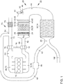
- FIG. 1 shows an embodiment of an exhaust gas aftertreatment system 20 according to the invention of an internal combustion engine 10.
- the internal combustion engine 10 has an outlet 12, in particular an exhaust manifold 14, which is connected to an exhaust system 22 of the internal combustion engine 10.
- the internal combustion engine 10 is designed as a self-igniting internal combustion engine 10 based on the diesel principle.
- a turbine 18 of an exhaust gas turbocharger 16 is arranged downstream of the outlet 12 and is used to drive a compressor 76 for supplying air to the internal combustion engine 10.
- the internal combustion engine 10 has an inlet side 68, which is connected to an intake tract 70 of the internal combustion engine 10.
- the intake tract 70 comprises a fresh gas line 72, in which an air filter 74 and downstream of the air filter 74 at least one compressor 76 of an exhaust gas turbocharger 18 are arranged.
- a charge air cooler 80 is arranged downstream of the compressor 76 and upstream of an inlet 78 of the internal combustion engine 10 in order to cool the fresh air compressed by the compressor 76 and thus further improve the filling of the combustion chambers of the internal combustion engine 10.
- the internal combustion engine 10 also has an outlet side 14, on which an exhaust manifold 22 is formed, which is connected to an exhaust system 20 of the internal combustion engine 10.
- the exhaust gas system 22 has a starting catalytic converter 24 near the engine, which is preferably designed as an oxidation catalytic converter 38.
- a support catalytic converter in particular a further oxidation catalytic converter 26 or a NOx storage catalytic converter 28, is arranged downstream of the starting catalytic converter 24.
- An electrically heatable catalytic converter 30 is arranged immediately downstream of the catalytic converter.
- the electrically heatable catalytic converter 30 has an electrical heating element, in particular an electrical heating disk 52, which is preferably connected to the supporting catalytic converter 26, 28 via a pin 54 to increase the mechanical stability.
- the electrically heatable catalytic converter 30 and the supporting catalytic converter 26, 28 are designed as metal catalytic converters in order to enable high mechanical stability.
- an arrangement close to the engine is understood to mean an arrangement with an exhaust gas run length of at most 60 cm, preferably of at most 40 cm, from the outlet 12 of the internal combustion engine 10.
- the total catalyst volume of starting catalytic converter 24, supporting catalytic converter 26, 28 and electrically heatable catalytic converter 30 is a maximum of 3 dm 3 for diesel engines with a displacement of less than 3 liters, in particular a maximum of the displacement of the Internal combustion engine 10.
- the total catalyst volume of starting catalyst 24, supporting catalyst 26, 28 and electrically heatable catalyst 40 is preferably a maximum of 80% of the displacement of the internal combustion engine 10, particularly preferably a maximum of 70% of the displacement.
- the starting catalyst 24 has a maximum of 40% of this total volume, preferably 30% of the total volume.
- the film thickness and / or cell number of the starting catalyst 24 can be below the values of the supporting catalyst 26, 28.
- the starting catalyst is designed with a cell density of 200 cells per square inch and with a film thickness of 40 ⁇ m, and the support catalyst 26, 28 with a cell density of 400 cells per square inch and a film thickness of 65 ⁇ m.
- the noble metal loading can differ in terms of specific loading and composition between the starting catalyst 24 and the support catalyst 26, 28. For an even faster starting of the starting catalyst 24, a 20% higher specific loading of the starting catalyst, preferably a 45% higher specific loading, particularly preferably a 70% higher specific loading, of the starting catalyst 24 compared to the support catalyst 26, 28 may be expedient.
- the electrically heatable catalyst can have a noble metal coating 40, in particular a platinum, rhodium or palladium coating, be uncoated, or be provided with a coating 42 as a hydrolysis catalyst 48.
- a noble metal coating 40 in particular a platinum, rhodium or palladium coating, be uncoated, or be provided with a coating 42 as a hydrolysis catalyst 48.
- the starting catalytic converter 24 and the support catalytic converter 26, 28 can have the same outside diameter D A and can be accommodated in a common casing, in particular a common housing. It is advantageous if a minimum distance of at least 0.5 mm, preferably of at least 1 mm, particularly preferably of 2.5 mm is maintained over at least 90% of the mutually facing end faces of the starting catalyst 24 and the support catalyst 26, 28 in order to prevent conductive heat transfer and to minimize heat transfer by thermal radiation.
- a particle filter 32 with a coating 34 for the selective, catalytic reduction of nitrogen oxides (SCR coating) is arranged downstream of the electrically heatable catalyst 30.
- a branch 60 of the exhaust system 22 is provided downstream of the particle filter 32, at which an exhaust duct 56 branches into a low-pressure exhaust gas recirculation 62 and an underbody duct 64, which connects the particle filter 32 to an end pipe of the exhaust system 22.
- the low-pressure exhaust gas recirculation 62 has an exhaust gas recirculation channel 82 which connects the exhaust gas channel 56 at the junction 60 downstream of the particle filter 32 with an opening 84 into the intake tract 70 connects downstream of the air filter 74 and upstream of the compressor 76.
- the low-pressure exhaust gas recirculation 62 has a low-pressure exhaust gas recirculation cooler 86, with which the recirculated exhaust gas is cooled in the intake tract 70 before it is mixed with the fresh air.
- a metering module 44 for metering in a reducing agent 46, in particular aqueous urea solution, is provided downstream of the electrically heatable catalyst 30 and upstream of the particle filter 32 with the SCR coating 34.
- the exhaust duct 56 of the exhaust system 22 has a deflection element 66 in the area between the electrically heatable catalyst 30 and the particle filter 32. The deflection of the exhaust gas flow creates a swirl which promotes mixing of the metered-in reducing agent 46 with the exhaust gas before it enters the particle filter 32 and thus improves the evaporation of the reducing agent and the uniform distribution over the cross section of the exhaust gas duct 56. This effect can optionally be supported by an exhaust gas mixer (not shown) in the deflection element 66.
- the electrically heatable catalyst 30 has a coating 42 for hydrolysis, for example a titanium dioxide coating, and is designed as a hydrolysis catalyst 48, it is advantageous if an injection opening 50 of the metering module 44 is directed onto the hydrolysis catalyst 48. This results in better evaporation of the reducing agent and an improved release of ammonia for the selective, catalytic reduction of nitrogen oxides on the SCR coating 34 of the particle filter 32.
- the metering module 44 is designed as a high-pressure metering module and has an injection pressure of at least 20 bar, preferably of at least 50 bar.
- One way to improve the raw emissions of the internal combustion engine 10 is to add exhaust gas to the fresh air in order to reduce the formation of nitrogen oxide emissions. It is advantageous if the recirculated exhaust gas is as cool as possible. For this reason, a low pressure exhaust gas recirculation cooler 86 is arranged in the low pressure exhaust gas recirculation system 62.
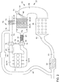
- FIG 2 An example of an exhaust gas aftertreatment system 20 that is not according to the invention is shown. With essentially the same structure as for Figure 1 only the differences are discussed below.
- the starting catalytic converter 24 is arranged further upstream in the exhaust system 22 and thus closer to the outlet 12 of the internal combustion engine 10.
- the starting catalytic converter 24 can be arranged upstream or downstream of a turbine 18 of the exhaust gas turbocharger 16.
- the starting catalytic converter 24 is preferably arranged downstream of the turbine 18.
- An exhaust gas funnel is formed between the starting catalytic converter 24 and the supporting catalytic converter 26, 28, as a result of which the distance between the starting catalytic converter 24 and the supporting catalytic converter 26, 28 is further increased.
- an SCR catalytic converter 36 can be arranged upstream of a particle filter 32 with an SCR coating 24, in which case the exhaust gas aftertreatment system 20 can have a particle filter 32 which has a noble metal coating to support particle reduction.
- the exhaust gas aftertreatment system 20 proposed according to the invention also offers advantages on the process side compared to the solutions known from the prior art.
- Methods are known in the prior art in which the exhaust-gas aftertreatment components are heated exclusively by means of internal engine measures, such as late fuel injection, a charge reduction, early opening of the exhaust valves, high-pressure exhaust gas recirculation or a combination of these measures. It is also known from the prior art to alternatively or additionally raise the exhaust gas temperature by catalytic conversion of unburned hydrocarbons or carbon monoxide on an oxidation catalyst as soon as the oxidation catalyst has reached its light-off temperature. For this purpose, a late post-injection is used in particular during or after the end of fuel in the combustion chamber.
- the catalytic heating can be applied much earlier than in the case of an undivided oxidation catalytic converter, in which the starting catalytic converter 24 and the supporting catalytic converter 26, 28 have to be warmed through.
- FIG. 3 Outlined course of the heating of the individual exhaust gas aftertreatment components.
- An exhaust gas temperature T EG is shown at different measuring points in the exhaust system 22 over time.
- the temperature curve of the exhaust gas temperature upstream of the starting catalytic converter 24 is shown in the first curve T1.
- the second curve T2 shows the course of the exhaust gas temperature immediately downstream of the starting catalytic converter 24.
- the third curve T3 illustrates the exhaust gas temperature immediately downstream of the electrically heatable catalytic converter 30.
- the fourth curve T4 shows the course of the temperature at the SCR coating 34 of the particle filter 32.
- the internal combustion engine 10 is started at a time t 1 . Due to the set load point or by taking known internal engine measures to increase the exhaust gas temperature T EG , the exhaust gas temperature upstream of the starting catalytic converter 24 is set above the light-off temperature T LOS of the starting catalytic converter 24. Also when the internal combustion engine 10 starts, the heating disk 52 of the electrically heatable catalytic converter 30 is energized and preferably regulated with a two-point controller to a temperature T LOP above the light-off temperature T LON of the SCR coating 34 of the particle filter 32. At a time t 2 , the light-off temperature T LOS in the starting catalytic converter 24 is exceeded and, alternatively or additionally, catalytic heating measures can be taken to further accelerate the heating up.
- the support catalytic converter 26, 28 is gradually warmed up and the energy requirement of the electrically heatable catalytic converter 30 decreases continuously, as can be seen from FIG Figure 3 shown longer and longer de-energized phases between the respective heating phases of the electrically heatable catalyst 30.
- the light-off temperature T LON of the SCR coating 34 of the particle filter 32 is reached and the reducing agent 46 is metered in by the metering module 44 and an associated highly efficient reduction of nitrogen oxides (NOx) can begin. If the light-off temperature T LON plus an applicable offset is permanently exceeded, no further electrical heating or catalytic heating is required to support the exhaust gas aftertreatment system 20.
- the starting catalytic converter 24 has two properties which make it noticeably noticeable compared to solutions known from the prior art: On the one hand, the lower volume and the lower heat conduction to the support catalytic converter 26, 28 enable the catalytic heating measures to be started more quickly. On the other hand, a faster conversion of nitrogen monoxide (NO) into nitrogen dioxide (NO2) is possible, the metering in of the reducing agent 46 taking place in time and thus the conversion of the nitrogen oxides (NOx) by the SCR coating earlier.
- NO nitrogen monoxide
- NO2 nitrogen dioxide
- the reducing agent 46 can be metered in when the support catalytic converter 26, 28 has not yet reached its light-off temperature T LOO , since the catalytic performance of the starting catalytic converter 24 is sufficient to convert a sufficient amount of nitrogen monoxide (NO) into nitrogen nitrogen dioxide (NO2) to oxidize.
- NO nitrogen monoxide
- NO2 nitrogen nitrogen dioxide
- the combination of starting catalytic converter 24 as the first components of the exhaust gas aftertreatment and the electrically heated catalytic converter 30 downstream of the supporting catalytic converter 26, 28 also allows the two essential parameters required for efficient nitrogen oxide (NOx) conversion to be provided on the SCR coating 34 of the particle filter 32 as quickly as possible: On the one hand, the sufficient oxidation of nitrogen monoxide (NO) to nitrogen dioxide (NO2) and, on the other hand, a sufficient gas temperature of the exhaust gas via the electrically heatable catalyst 30, regardless of the thermal conditioning of the oxidative catalyst volume of the support catalyst 26, 28. Even with the support catalyst 26 still completely inactive , 28, NOx conversion is possible on the SCR coating 34 of the particle filter 32.
- NOx nitrogen oxide
- the invention relates to an exhaust gas aftertreatment system 20 for a diesel engine.
- An oxidation catalytic converter 26 or a NOx storage catalytic converter 28 is arranged downstream of an outlet 12 of the internal combustion engine 10, which is immediately followed by an electrically heatable catalytic converter 30, so that the electrically heatable catalytic converter 30 can heat the exhaust gas flow downstream of the oxidation catalytic converter 26 or NOx storage catalytic converter 28 and the oxidation catalytic converter 26 or the NOx storage catalytic converter 28 are additionally heated by the electrically heatable catalytic converter 30.
- a particle filter 32 with an SCR coating 34 is provided downstream of the electrically heatable catalytic converter 30, which can be heated more quickly to a light-off temperature by the heat input into the electrically heatable catalytic converter 30 after a cold start of the internal combustion engine 10.
- a starting catalytic converter 24 is provided downstream of the outlet 12 and upstream of the oxidation catalytic converter 26 or NOx storage catalytic converter 28 Oxidation catalytic converter 26 or NOx storage catalytic converter 28 is spaced apart in order to avoid conductive heat transfer between the starting catalytic converter 24 and the oxidation catalytic converter 26 or the NOx storage catalytic converter 28 and thus to enable the starting catalytic converter 24 to warm up more quickly after a cold start of the internal combustion engine 10.
Landscapes
- Engineering & Computer Science (AREA)
- Chemical & Material Sciences (AREA)
- Chemical Kinetics & Catalysis (AREA)
- Combustion & Propulsion (AREA)
- Mechanical Engineering (AREA)
- General Engineering & Computer Science (AREA)
- Health & Medical Sciences (AREA)
- Toxicology (AREA)
- Exhaust Gas After Treatment (AREA)
Description
- Die Erfindung betrifft ein Abgasnachbehandlungssystem für einen Verbrennungsmotor sowie ein Verfahren zur Abgasnachbehandlung eines Verbrennungsmotors gemäß dem Oberbegriff der unabhängigen Patentansprüche.
- Die aktuelle und eine zukünftig immer schärfer werdende Abgasgesetzgebung stellen hohe Anforderungen an die motorischen Rohemissionen und die Abgasnachbehandlung von Verbrennungsmotoren. Dabei stellen die Forderungen nach einem weiter sinkenden Verbrauch und die weitere Verschärfung der Abgasnormen hinsichtlich der zulässigen Stickoxid-Emissionen eine Herausforderung für die Motorenentwickler dar. Bei Ottomotoren erfolgt die Abgasreinigung in bekannter Weise über einen Drei-Wege-Katalysator, sowie dem Drei-Wege-Katalysator vor- und nachgeschaltete weitere Katalysatoren. Bei Dieselmotoren finden aktuell Abgasnachbehandlungssysteme Verwendung, welche einen Oxidationskatalysator oder NOx-Speicherkatalysator, einen Katalysator zur selektiven katalytischen Reduktion von Stickoxiden (SCR-Katalysator) sowie einen Partikelfilter zur Abscheidung von Rußpartikeln und gegebenenfalls weitere Katalysatoren aufweisen. Als Reduktionsmittel wird dabei bevorzugt Ammoniak verwendet. Weil der Umgang mit reinem Ammoniak aufwendig ist, wird bei Fahrzeugen üblicherweise eine synthetische, wässrige Harnstofflösung verwendet, die in einer dem SCR-Katalysator vorgeschalteten Mischeinrichtung mit dem heißen Abgasstrom vermischt wird. Durch diese Vermischung wird die wässrige Harnstofflösung erhitzt, wobei die wässrige Harnstofflösung Ammoniak im Abgaskanal freisetzt. Eine handelsübliche, wässrige Harnstofflösung setzt sind im Allgemeinen aus 32,5% Harnstoff und 67,5% Wasser zusammen.
- Um nach einem Kaltstart des Verbrennungsmotors die Abgasnachbehandlungskomponenten möglichst schnell auf die benötigte Betriebstemperatur zu bringen, ist eine möglichst motornahe Anordnung der Abgasnachbehandlungskomponenten wünschenswert. Dies ist jedoch nicht immer möglich, da der Bauraum begrenzt ist. Daher werden der SCR-Katalysator und/oder der Rußpartikelfilter oftmals in einer motorfernen Unterbodenlage eines Kraftfahrzeuges angeordnet. Für eine hocheffiziente Abgasreinigung ist jedoch eine schnelle Durchwärmung der gesamten Abgasnachbehandlungskomponenten erforderlich. In den meisten Abgasanlagen erfolgt dies rein thermisch, das heißt durch eine Aufheizung der Abgasnachbehandlungskomponenten durch das Abgas des Verbrennungsmotors. Dabei werden die in Strömungsrichtung dem Auslass des Verbrennungsmotors folgenden Abgasnachbehandlungskomponenten nach und nach erwärmt. Diese Strategie kann durch motorische Heizmaßnahmen, wie beispielsweise die Wahl eines späten Einspritzzeitpunktes oder einer Nacheinspritzung von Kraftstoff in die Brennräume des Verbrennungsmotors unterstützt werden. Bei einem Partikelfilter mit einer Beschichtung zur selektiven, katalytischen Reduktion von Stickoxiden (SCR-Beschichtung), welche einem Oxidationskatalysator nachgeschaltet ist, kann dies bei einem Betrieb wie in dem NEFZ-Prüfzyklus dazu führen, dass die SCR-Beschichtung des Partikelfilters erst einige Minuten nach dem Kaltstart des Verbrennungsmotors ein Temperaturfenster erreicht, in welchem eine wirksame Reduktion von Stickoxiden durch den SCR-Katalysator erfolgen kann.
- Aus dem Stand der Technik ist bekannt, diesem Mangel durch einen vorgeschalteten NOx-Speicherkatalysator anstelle des Oxidationskatalysators zu begegnen. Da der NOx-Speicherkatalysator in der Abgasanlage stromaufwärts des Partikelfilters mit SCR-Beschichtung angeordnet ist, erwärmt sich dieser nach einem Kaltstart schneller auf seine Anspringtemperatur und kann das Zeitfenster verkürzen, ab dem das Abgasnachbehandlungssystem effizient die Stickoxid-Emissionen verringern kann. Nachteilig an einem solchen NOx-Speicherkatalysator ist jedoch, dass neben den zusätzlichen Kosten für eine ausreichende einspeicherbare NOx-Masse sinnvollerweise ein vergleichsweise großes Volumens des NOx-Speicherkatalysators von mindestens 1dm3 pro Liter Hubvolumen des Verbrennungsmotors vorgehalten werden muss, was die Aufwärmung der in Strömungsrichtung dahinter liegenden Abgasnachbehandlungskomponenten weiter verzögert.
- Ebenfalls ist aus dem Stand der Technik der Einsatz von elektrisch beheizbaren Katalysatoren zur schnelleren Erwärmung der Komponenten zur Abgasnachbehandlung bekannt. Üblicherweise sind für eine ausreichende mechanische Stabilität die Heizscheiben der elektrisch beheizbaren Katalysatoren mit einem Stützkatalysator verstiftet. Diese Einheit wird üblicherweise als Oxidationskatalysator ausgeführt, wobei der elektrisch beheizbare Katalysator vor oder hinter dem Stützkatalysator angeordnet ist. Sowohl der elektrisch beheizbare Oxidationskatalysator als auch der Stützkatalysator werden dabei vorzugsweise als Metallkatalysatoren ausgeführt.
- Die Anordnung eines elektrisch beheizbaren Katalysators vor dem Stützkatalysator hat den Nachteil, dass vor nennenswertem Wärmeeintrag in den Partikelfilter mit SCR-Beschichtung zunächst der Stützkatalysator selbst durchwärmt werden muss, was wiederum eine zeitliche Verzögerung des Erreichens der Anspringtemperatur der SCR-Beschichtung auf dem Partikelfilter zur Folge hat.
- Aus der
DE 10 2005 013 707 A1 ist ein Abgasnachbehandlungssystem für einen Verbrennungsmotor bekannt, bei dem in Strömungsrichtung eines Abgases des Verbrennungsmotors durch die Abgasanlage des Verbrennungsmotors ein Oxidationskatalysator, ein Dieselpartikelfilter und ein SCR-Katalysator angeordnet sind. Dabei wird stromabwärts des Partikelfilters und stromaufwärts des SCR-Katalysators wässrige Harnstofflösung in die Abgasanlage eindosiert, um die Stickoxide auf dem SCR-Katalysator zu reduzieren. Dabei ist an dem Oxidationskatalysator oder an dem SCR-Katalysator eingangsseitig ein elektrisches Heizelement vorgesehen, um das Temperaturniveau in der Abgasanlage anzuheben. Nachteilig an einer solchen Lösung ist jedoch, dass bei einem Heizelement, welches dem Oxidationskatalysator vorgeschaltet ist, der Oxidationskatalysator und der Partikelfilter durchgewärmt werden müssen, bevor eine signifikante Erwärmung des SCR-Katalysators erfolgt. Bei einer Anordnung des elektrischen Heizelements unmittelbar vor dem SCR-Katalysator kann das elektrische Heizelement nicht zur Verbesserung der HC- und CO-Emissionen in der Kaltstartphase beitragen. - Die Anordnung des elektrisch beheizbaren Katalysators hinter dem Stützkatalysator ist in dieser Hinsicht vorteilhafter, da sowohl der Partikelfilter mit der SCR-Beschichtung schneller durchwärmt wird als auch die Aufbereitung der wässrigen Harnstofflösung durch die schnellere Wärmebereitstellung hinter dem Oxidationskatalysator unterstützt wird. Nachteilig ist jedoch in beiden Fällen die hohe axiale Wärmeleitfähigkeit der Metallkatalysatoren. Gewünscht wird sowohl eine schnelle Aktivierung des Oxidationskatalysators zur Konvertierung von Kohlenwasserstoff-(HC) und Kohlenstoffmonoxid-(CO)-Emissionen sowie zur Oxidation von Stickstoffmonoxid (NO) zu Stickstoffdioxid (NO2) als auch eine schnelle Erwärmung des Partikelfilters mit der SCR-Beschichtung auf eine Anspringtemperatur der SCR-Beschichtung.
- Aus der
DE 10 2008 013 777 A1 ist eine Abgasanlage für einen Verbrennungsmotor bekannt, bei der ein Heizelement stromabwärts eines Auslasses des Verbrennungsmotors und stromaufwärts eines Oxidationskatalysators angeordnet ist, um Wärmeenergie in das Abgas der Verbrennungsmotors einzuleiten. Dabei ist stromabwärts des Oxidationskatalysators ein Katalysator zur selektiven, katalytischen Reduktion von Stickoxiden vorgesehen, um die Stickoxide im Abgas zu reduzieren. Dabei ist dem Verbrennungsmotor bzw. der Abgasanlage ein Steuergerät zugeordnet, welches mit dem Heizelement in Verbindung steht und das Heizelement in Abhängigkeit von der Temperatur des SCR-Katalysators zuschaltet. - Aus der
DE 10 2012 222 292 A1 ist ein Abgasnachbehandlungssystem für einen Verbrennungsmotor bekannt, welches einen Vorratsbehälter mit Absorptionsmitteln, einen elektrisch beheizbaren Katalysator und einen SCR-Katalysator aufweist. Dabei absorbiert das Absorbtionsmittel das Wasser oder den Wasserdampf im Abgas des Verbrennungsmotors. - Die
DE 10 2012 205 534 A1 offenbart ein Verfahren zum elektrischen Aufheizen eines Bauteils in einem Abgasnachbehandlungssystem eines Kraftfahrzeuges, wobei an dem Kraftfahrzeug ein Solarmodul angeordnet ist und die Energie zum Aufheizen der Abgasnachbehandlungskomponente zumindest anteilig aus dem Solarmodul bereitgestellt wird. - Aus der
DE 10 2015 200 023 A1 ist ein Abgasnachbehandlungssystem mit einem Stickoxid-Speicherkatalysator und einem dem Stickoxid-Speicherkatalysator nachgeschalteten SCR-Katalysator bekannt. Dabei ist stromaufwärts des Stickoxid-Speicherkatalysators ein elektrisches Heizelement vorgesehen, um den Abgasstrom zu beheizen. - Die
WO 2017 / 168 156 A1 offenbart ein Abgasnachbehandlungssystem mit einem NOx-Speicherkatalysator, einem SCR-Katalysator und einem elektrischen Heizelement, wobei das Heizelement stromabwärts des NOx-Speicherkatalysators angeordnet ist. - Aufgabe der Erfindung ist es, die SCR-Beschichtung des Partikelfilters bei einem moderaten Mehrverbrauch möglichst schnell nach einem Kaltstart des Verbrennungsmotors auf eine Anspringtemperatur zu bringen, bei der eine wirksame Reduktion von Stickoxiden durch die SCR-Beschichtung möglich ist.
- Erfindungsgemäß wird diese Aufgabe durch ein Abgasnachbehandlungssystem gelöst, bei dem in einer Abgasanlage eines Verbrennungsmotors, insbesondere eines Dieselmotors, stromabwärts eines Auslasses des Verbrennungsmotors ein Oxidationskatalysator oder ein NOx-Speicherkatalysator und unmittelbar stromabwärts des Oxidationskatalysators oder NOx-Speicherkatalysators ein elektrisch beheizbarer Katalysator und weiter stromabwärts ein Partikelfilter mit einer SCR-Beschichtung oder ein SCR-Katalysator angeordnet sind, wobei dem Oxidationskatalysator oder dem NOx-Speicherkatalysator ein Startkatalysator vorgeschaltet ist, welcher in der Abgasanlage von dem Oxidationskatalysator oder dem NOx-Speicherkatalysator beabstandet ist, um eine konduktive Wärmeübertragung von dem Oxidationskatalysator oder NOx-Speicherkatalysator auf den Startkatalysator zu minimieren.
- Durch die in den abhängigen Ansprüchen aufgeführten Merkmale sind vorteilhafte Verbesserungen und Weiterentwicklungen des im unabhängigen Anspruch angegebenen Abgasnachbehandlungssystems möglich.
- In einer bevorzugten Ausführungsform der Erfindung ist vorgesehen, dass der Startkatalysator als Oxidationskatalysator ausgeführt ist.
- In einer vorteilhaften Ausführungsform des Abgasnachbehandlungssystems ist vorgesehen, dass das aufsummierte Katalysatorvolumen des Startkatalysators, des Oxidationskatalysators oder des NOx-Speicherkatalysators und des elektrisch beheizbaren Katalysators maximal so groß wie der Hubraum des Verbrennungsmotors, bevorzugt maximal 80% des Hubraums des Verbrennungsmotors, besonders bevorzugt maximal 70% des Hubraums des Verbrennungsmotors, ist.
- Besonders bevorzugt ist dabei, wenn der Startkatalysator maximal 40 % des gesamten Katalysatorvolumens der Summe der Katalysatorvolumina von Startkatalysator, Oxidationskatalysator und elektrisch beheizbarem Katalysator, vorzugsweise maximal 30 % des gesamten Katalysatorvolumens dieser Katalysatoren aufweist.
- Erfindungsgemäß ist vorgesehen, dass der Startkatalysator eine geringe Folienstärke und/oder eine geringere Zellzahl als der Oxidationskatalysator oder der NOx-Speicherkatalysator aufweist.
- Erfindungsgemäß ist vorgesehen, dass der Startkatalysator und der Oxidationskatalysator oder der NOx-Speicherkatalysator denselben Außendurchmesser aufweisen und in einem gemeinsamen Mantel untergebracht sind. Dabei ist es vorteilhaft, wenn über zumindest 90% der zugewandten Stirnflächen ein Mindestabstand zwischen der Abström-Stirnfläche des Startkatalysators und der Anström-Stirnfläche des Oxidationskatalysators oder der NOx-Speicherkatalysator von mindestens 0,5 mm, vorzugsweise von mindestens einem Millimeter, besonders bevorzugt von mindestens 2,5 mm eingehalten wird. Dabei sollte der Abstand 10 mm, vorzugsweise 5 mm nicht übersteigen.
- Nicht erfindungsgemäß kann der Startkatalysator auch gegenüber dem Oxidationskatalysator einen abweichenden, insbesondere einen kleineren Außendurchmesser aufweisen. In diesem Fall ist die Einhaltung der genannten Mindestabstände durch einen zwischenliegenden Trichter, welcher den Abgaskanalquerschnitt von dem Startkatalysator auf den Abgaskanalquerschnitt des Oxidationskatalysators oder des NOx-Speicherkatalyators anpasst, sichergestellt. Alternativ ist die Anordnung des Startkatalysators stromabwärts des Auslasses des Verbrennungsmotors und stromaufwärts zumindest einer Turbine eines Abgasturboladers des Verbrennungsmotors oder in einem Anströmtrichter des Oxidationskatalysators oder des NOx-Speicherkatalysators denkbar.
- Gemäß einer bevorzugten Ausführungsform der Erfindung ist vorgesehen, dass der elektrisch beheizbare Katalysator eine Edelmetallbeschichtung, insbesondere Platin-, Palladium- oder Rhodiumbeschichtung aufweist oder mit einer Beschichtung als Hydrolysekatalysator, insbesondere mit einer Titandioxidbeschichtung, versehen ist.
- Besonders bevorzugt ist dabei, wenn an der Abgasanlage ein Dosiermodul zur Eindosierung eines Reduktionsmittels angeordnet ist, wobei eine Einspritzöffnung des Dosiermoduls zumindest teilweise auf den Hydrolysekatalysator gerichtet ist. In diesem Fall kann es sinnvoll sein, zumindest einen Teil des Reduktionsmittels, insbesondere der wässrigen Harnstofflösung, direkt auf den Hydrolysekatalysator einzudosieren, mit dem Ziel einer verbesserten Verdampfung und Umsetzung der wässrigen Harnstofflösung in Ammoniak (NH3).
- In einer vorteilhaften Verbesserung ist vorgesehen, dass stromabwärts des elektrisch beheizbaren Katalysators und stromaufwärts des Partikelfilters mit der SCR-Beschichtung ein Dosiermodul zur Eindosierung eines Reduktionsmittels angeordnet ist, wobei die Eindosierung des Reduktionsmittels mit einem Einspritzdruck von mindestens 20 bar, vorzugsweise von mindestens 50 bar erfolgt.
- Erfindungsgemäß wird ein Verfahren zur Abgasnachbehandlung eines Verbrennungsmotors mit dem oben genannten erfindungsgemäßen Abgasnachbehandlungssystem vorgeschlagen, welches folgende Schritte umfasst:
- Beheizen der Abgasanlage durch den Verbrennungsmotor, wobei die Abgastemperatur des Verbrennungsmotors durch innermotorische Maßnahmen erhöht wird;
- gleichzeitiges Beheizen des elektrisch beheizbaren Katalysators bis eine Temperatur der SCR-Beschichtung des Partikelfilters erreicht ist, welche oberhalb der Light-Off-Temperatur der SCR-Beschichtung liegt;
- wobei eine Wärmeleitung von dem elektrisch beheizbaren Katalysator auf den Startkatalysator unterbunden wird, indem der Startkatalysator von dem elektrisch beheizbaren Katalysator derart beabstandet angeordnet wird, dass eine konduktive Wärmeübertragung zwischen dem elektrisch beheizbaren Katalysator und dem Startkatalysator ausschließlich über eine Wand des Abgaskanals erfolgen kann.
- Die verschiedenen in dieser Anmeldung genannten Ausführungsformen der Erfindung sind, sofern im Einzelfall nicht anders ausgeführt, mit Vorteil miteinander kombinierbar.
- Die Erfindung wird nachfolgend in Ausführungsbeispielen anhand der zugehörigen Zeichnungen erläutert. Es zeigen:
- Figur 1
- ein Ausführungsbeispiel eines erfindungsgemäßen Abgasnachbehandlungssystems für einen Verbrennungsmotor;
- Figur 2
- ein Beispiel eines nicht erfindungsgemäßen Abgasnachbehandlungssystems für einen Verbrennungsmotor; und
- Figur 3
- ein Diagramm zur Visualisierung eines erfindungsgemäßen Verfahrens zur Abgasnachbehandlung eines Verbrennungsmotors.
-
Figur 1 zeigt ein Ausführungsbeispiel eines erfindungsgemäßen Abgasnachbehandlungssystems 20 eines Verbrennungsmotors 10. Der Verbrennungsmotor 10 weist einen Auslass 12, insbesondere einen Abgaskrümmer 14 auf, welcher mit einer Abgasanlage 22 des Verbrennungsmotors 10 verbunden ist. Der Verbrennungsmotor 10 ist als selbstzündender Verbrennungsmotor 10 nach dem Diesel-Prinzip ausgeführt. In der Abgasanlage 22 des Verbrennungsmotors 10 ist stromabwärts des Auslasses 12 eine Turbine 18 eines Abgasturboladers 16 angeordnet, mit welcher ein Verdichter 76 zur Luftversorgung des Verbrennungsmotors 10 angetrieben wird. Der Verbrennungsmotor 10 weist eine Einlassseite 68 auf, welche mit einem Ansaugtrakt 70 des Verbrennungsmotors 10 verbunden ist. Der Ansaugtrakt 70 umfasst eine Frischgasleitung 72, in welcher ein Luftfilter 74 und stromabwärts des Luftfilters 74 mindestens ein Verdichter 76 eines Abgasturboladers 18 angeordnet ist. Stromabwärts des Verdichters 76 und stromaufwärts eines Einlasses 78 des Verbrennungsmotors 10 ist ein Ladeluftkühler 80 angeordnet, um die durch den Verdichter 76 komprimierte Frischluft abzukühlen und somit die Füllung der Brennräume des Verbrennungsmotors 10 weiter zu verbessern. Der Verbrennungsmotor 10 weist ferner eine Auslassseite 14 auf, an welcher ein Abgaskrümmer 22 ausgebildet ist, welcher mit einem Abgassystem 20 des Verbrennungsmotors 10 verbunden ist. - Die Abgasanlage 22 weist stromabwärts der Turbine 18 einen motornahen Startkatalysator 24 auf, welcher vorzugsweise als Oxidationskatalysator 38 ausgebildet ist. Stromabwärts des Startkatalysators 24 ist ein Stützkatalysator, insbesondere ein weiterer Oxidationskatalysator 26 oder ein NOx-Speicherkatalysator 28 angeordnet. Unmittelbar stromabwärts des Stützkatalysators ist ein elektrisch beheizbarer Katalysator 30 angeordnet. Der elektrisch beheizbare Katalysator 30 weist ein elektrisches Heizelement, insbesondere eine elektrische Heizscheibe 52 auf, welche vorzugsweise mit dem Stützkatalysator 26, 28 zur Erhöhung der mechanischen Stabilität über eine Verstiftung 54 verbunden ist. Dabei sind der elektrisch beheizbare Katalysator 30 und der Stützkatalysator 26, 28 als Metallkatalysatoren ausgeführt, um eine hohe mechanische Stabilität zu ermöglichen. Unter einer motornahen Anordnung ist in diesem Zusammenhang eine Anordnung mit einer Abgaslauflänge von maximal 60 cm, vorzugsweise von maximal 40 cm, ab dem Auslass 12 des Verbrennungsmotors 10 zu verstehen. Das aufsummierte Katalysatorvolumen von Startkatalysator 24, Stützkatalysator 26, 28 und elektrisch beheizbarem Katalysator 30 liegt für Dieselmotoren mit weniger als 3 Liter Hubraum bei maximal 3 dm3, insbesondere maximal beim Hubvolumen des Verbrennungsmotors 10. Bevorzugt beträgt das aufsummierte Katalysatorvolumen von Startkatalysator 24, Stützkatalysator 26, 28 und elektrisch beheizbarem Katalysator 40 maximal 80% des Hubraums des Verbrennungsmotors 10, besonders bevorzugt maximal 70% des Hubraums. Der Startkatalysator 24 weist dabei maximal 40% dieses aufsummierten Volumens, vorzugsweise 30% des Gesamtvolumens auf. Die Folienstärke und/oder Zellzahl des Startkatalysators 24 können unterhalb der Werte des Stützkatalysators 26, 28 liegen. So wird der Startkatalysator beispielsweise mit einer Zelldichte von 200 Zellen pro Quadratinch und mit 40 µm Folienstärke und der Stützkatalysator 26, 28 mit einer Zelldichte von 400 Zellen pro Quadratinch und einer Folienstärke von 65 µm ausgeführt. Ebenso kann die Edelmetallbeladung hinsichtlich spezifischer Beladung und Zusammensetzung zwischen dem Startkatalysator 24 und dem Stützkatalysator 26, 28 unterschiedlich sein. Für ein noch schnelleres Anspringen des Startkatalysators 24 kann eine um 20% höhere spezifische Beladung des Startkatalysators, vorzugsweise eine um 45% höhere spezifische Beladung, besonders bevorzugt eine um 70% höhere spezifische Beladung, des Startkatalysators 24 gegenüber dem Stützkatalysator 26, 28 sinnvoll sein.
- Der elektrisch beheizbare Katalysator kann eine Edelmetallbeschichtung 40, insbesondere eine Platin-, Rhodium- oder Paladiumbeschichtung, aufweisen, unbeschichtet sein, oder mit einer Beschichtung 42 als Hydrolysekatalysator 48 versehen sein.
- Der Startkatalysator 24 und der Stützkatalysator 26, 28 können denselben Außendurchmesser DA aufweisen und in einem gemeinsamen Mantel, insbesondere einem gemeinsamen Gehäuse, untergebracht sein. Dabei ist es vorteilhaft, wenn über zumindest 90% der einander zugewandten Stirnflächen von Startkatalysator 24 und Stützkatalysator 26, 28 ein Mindestabstand von mindestens 0,5mm, vorzugsweise von mindestens 1mm, besonders bevorzugt von 2,5mm eingehalten wird, um eine konduktive Wärmeübertragung zu unterbinden und eine Wärmeübertragung durch Wärmestrahlung zu minimieren.
- Stromabwärts des elektrisch beheizbaren Katalysators 30 ist ein Partikelfilter 32 mit einer Beschichtung 34 zur selektiven, katalytischen Reduktion von Stickoxiden (SCR-Beschichtung) angeordnet. Stromabwärts des Partikelfilters 32 ist eine Verzweigung 60 der Abgasanlage 22 vorgesehen, an der sich ein Abgaskanal 56 in eine Niederdruck-Abgasrückführung 62 und einen Unterbodenkanal 64 verzweigt, welcher den Partikelfilter 32 mit einem Endrohr der Abgasanlage 22 verbindet. Die Niederdruck-Abgasrückführung 62 weist einen Abgasrückführungskanal 82 auf, welcher den Abgaskanal 56 an der Verzweigung 60 stromabwärts des Partikelfilters 32 mit einer Einmündung 84 in den Ansaugtrakt 70 stromabwärts des Luftfilters 74 und stromaufwärts des Verdichters 76 verbindet. Die Niederdruck-Abgasrückführung 62 weist einen Niederdruck-Abgasrückführungs-Kühler 86 auf, mit welchem das zurückgeführte Abgas vor der Zumischung zur Frischluft im Ansaugtrakt 70 abgekühlt wird.
- Stromabwärts des elektrisch beheizbaren Katalysators 30 und stromaufwärts des Partikelfilters 32 mit der SCR-Beschichtung 34 ist ein Dosiermodul 44 zur Eindosierung eines Reduktionsmittels 46, insbesondere wässriger Harnstofflösung, vorgesehen. Dabei weist der Abgaskanal 56 der Abgasanlage 22 in dem Bereich zwischen dem elektrisch beheizbaren Katalysator 30 und dem Partikelfilter 32 ein Umlenkelement 66 auf. Durch die Umlenkung des Abgasstroms entsteht eine Verwirbelung, welche eine Vermischung des eindosierten Reduktionsmittels 46 mit dem Abgas vor einem Eintritt in den Partikelfilter 32 begünstigt und somit die Verdampfung des Reduktionsmittels und die Gleichverteilung über den Querschnitt des Abgaskanals 56 verbessert. Dieser Effekt kann gegebenenfalls durch einen nicht dargestellten Abgasmischer im Umlenkelement 66 unterstützt werden.
- Weist der elektrisch beheizbare Katalysator 30 eine Beschichtung 42 zur Hydrolyse, beispielsweise eine Titandioxidbeschichtung, auf und ist als Hydrolysekatalysator 48 ausgebildet, so ist es vorteilhaft, wenn eine Einspritzöffnung 50 des Dosiermoduls 44 auf den Hydrolysekatalysator 48 gerichtet ist. Dadurch wird eine bessere Verdampfung des Reduktionsmittels und eine verbesserte Freisetzung von Ammoniak zur selektiven, katalytischen Reduktion von Stickoxiden auf der SCR-Beschichtung 34 des Partikelfilters 32 erreicht. Zur besseren Gemischaufbereitung des Reduktionsmittels 46 ist es vorteilhaft, wenn das Dosiermodul 44 als Hochdruck-Dosiermodul ausgebildet ist und einen Einspritzdruck von mindestens 20 bar, vorzugsweise von mindestens 50 bar aufweist.
- Durch die zunehmende Verschärfung der Abgasgesetzgebung, insbesondere in Bezug auf die Stickoxid-Emissionen, ist es notwendig, innermotorische Maßnahmen und Maßnahmen zur Abgasnachbehandlung zu verbinden. Eine Möglichkeit, die Rohemissionen des Verbrennungsmotors 10 zu verbessern, besteht darin, der Frischluft Abgas zuzumischen, um die Bildung von Stickoxid-Emissionen zu verringern. Dabei ist es vorteilhaft, wenn das zurückgeführte Abgas möglichst kühl ist. Aus diesem Grund ist in der Niederdruck-Abgasrückführung 62 ein Niederdruck-Abgasrückführungs-Kühler 86 angeordnet.
- Um die Emissionen, insbesondere die Stickoxid-Emissionen, in der Startphase des Verbrennungsmotors 10 zu verbessern, ist es notwendig, die Stickoxid-reduzierenden Abgasnachbehandlungskomponenten, insbesondere den NOx-Speicherkatalysator 28 und den Partikelfilter 32 mit der SCR-Beschichtung 34 möglichst schnell auf eine Anspringtemperatur aufzuheizen. Ferner ist es notwendig, zur Reduzierung der Emissionen an unverbrannten Kohlenwasserstoffen (HC) und Kohlenstoffmonoxid (CO) zumindest einen der oxidativ wirksamen Katalysatoren 24, 26, 28, 30 auf seine Light-Off-Temperatur aufzuheizen, ab der eine effiziente Umsetzung dieser Emissionen möglich ist.
- In
Figur 2 ist ein Beispiel eines nicht erfindungsgemäßen Abgasnachbehandlungssystems 20 dargestellt. Bei im Wesentlichen gleichem Aufbau wie zuFigur 1 ausgeführt wird im Folgenden nur auf die Unterschiede eingegangen. Der Startkatalysator 24 ist in der Abgasanlage 22 weiter stromaufwärts und somit näher an dem Auslass 12 des Verbrennungsmotors 10 angeordnet. Dabei kann der Startkatalysator 24 stromaufwärts oder stromabwärts einer Turbine 18 des Abgasturboladers 16 angeordnet werden. Vorzugsweise ist der Startkatalysator 24 stromabwärts der Turbine 18 angeordnet. Zwischen dem Startkatalysator 24 und dem Stützkatalysator 26, 28 ist ein Abgastrichter ausgebildet, wodurch der Abstand zwischen Startkatalysator 24 und Stützkatalysator 26, 28 weiter vergrößert wird. Dabei wird eine Wärmeübertragung zwischen dem Startkatalysator 24 und dem Stützkatalysator 26, 28 mit Ausnahme der konvektiven Wärmeübertragung durch den Abgasstrom minimiert. Ferner kann stromaufwärts eines Partikelfilters 32 mit einer SCR-Beschichtung 24 ein SCR-Katalysator 36 angeordnet sein, wobei das Abgasnachbehandlungssystem 20 in diesem Fall einen Partikelfilter 32 aufweist kann, welcher zur Unterstützung der Partikelminderung eine Edelmetallbeschichtung aufweist. - Dabei bietet das erfindungsgemäß vorgeschlagene Abgasnachbehandlungssystem 20 auch verfahrensseitig Vorteile gegenüber den aus dem Stand der Technik bekannten Lösungen. Im Stand der Technik sind Verfahren bekannt, bei denen das Aufheizen der Abgasnachbehandlungskomponenten ausschließlich durch innermotorische Maßnahmen wie eine späte Kraftstoffeinspritzung, eine Füllungsreduzierung, eine frühes Öffnen der Auslassventile, eine Hochdruck-Abgasrückführung oder eine Kombination dieser Maßnahmen erfolgt. Ebenso ist aus dem Stand der Technik bekannt, die Abgastemperatur alternativ oder zusätzlich durch eine katalytische Umsetzung von unverbrannten Kohlenwasserstoffen oder Kohlenstoffmonoxid auf einem Oxidationskatalysator anzuheben, sobald der Oxidationskatalysator seine Light-Off-Temperatur erreicht hat. Dazu wird insbesondere eine späte Nacheinspritzung während oder nach dem Brennende des Kraftstoffs im Brennraum genutzt. Da die Anspringtemperatur im Startkatalysator gegenüber dem nachgeschalteten Stützkatalysator 26, 28 schneller ansteigt und die Wärmeleitung auf ein Mindestmaß über die Wände 58 des Abgaskanals 56 reduziert ist, kann die katalytische Heizung deutlich früher als bei einem ungeteilten Oxidationskatalysator angewendet werden, bei dem der Startkatalysator 24 und der Stützkatalysator 26, 28 durchgewärmt werden müssen.
- Insgesamt ergibt sich somit nach einem Kaltstart des Verbrennungsmotors 10 ein in
Fig.3 skizzierter Verlauf des Aufheizens der einzelnen Abgasnachbehandlungskomponenten. Dabei ist jeweils eine Abgastemperatur TEG an unterschiedlichen Messpunkten in der Abgasanlage 22 im zeitlichen Verlauf dargestellt. Dabei ist in der ersten Kurve T1 der Temperaturverlauf der Abgastemperatur stromaufwärts des Startkatalysators 24 dargestellt. Die zweite Kurve T2 zeigt den Verlauf der Abgastemperatur unmittelbar stromabwärts des Startkatalysators 24. Die dritte Kurve T3 illustriert die Abgastemperatur unmittelbar stromabwärts des elektrisch beheizbaren Katalysators 30. Die vierte Kurve T4 stellt den Verlauf der Temperatur an der SCR-Beschichtung 34 des Partikelfilters 32 dar. - Zu einem Zeitpunkt t1 wird der Verbrennungsmotor 10 gestartet. Bedingt durch den eingestellten Lastpunkt oder durch Ergreifen bekannter innermotorischer Maßnahmen zur Steigerung der Abgastemperatur TEG wird die Abgastemperatur vor dem Startkatalysator 24 oberhalb der Light-Off-Temperatur TLOS des Startkatalysators 24 eingestellt. Ebenfalls mit Motorstart des Verbrennungsmotors 10 wird die Heizscheibe 52 des elektrisch beheizbaren Katalysators 30 bestromt und vorzugsweise mit einem Zweipunktregler auf eine Temperatur TLOP oberhalb der Light-Off-Temperatur TLON der SCR-Beschichtung 34 des Partikelfilters 32 eingeregelt. Zu einem Zeitpunkt t2 wird die Light-Off-Temperatur TLOS im Startkatalysator 24 überschritten und alternativ oder zusätzlich können katalytische Heizmaßnahmen zur weiteren Beschleunigung des Aufheizens erfolgen. Im weiteren zeitlichen Verlauf wird der Stützkatalysator 26, 28 allmählich durchwärmt und der Energiebedarf des elektrisch beheizbaren Katalysators 30 nimmt kontinuierlich ab, erkennbar durch die in
Figur 3 dargestellten immer länger werdenden unbestromten Phasen zwischen den jeweiligen Heizphasen des elektrisch beheizbaren Katalysators 30. Zu einem Zeitpunkt t3 wird die Light-Off-Temperatur TLON der SCR-Beschichtung 34 des Partikelfilters 32 erreicht und die Eindosierung des Reduktionsmittels 46 durch das Dosiermodul 44 und eine damit verbundene hocheffiziente Reduzierung der Stickoxide (NOx) kann beginnen. Bei dauerhafter Überschreitung der Light-Off-Temperatur TLON zuzüglich eines applizierbaren Offsets ist keine weitere elektrische Beheizung oder katalytische Beheizung zur Unterstützung des Abgasnachbehandlungssystems 20 mehr erforderlich. - Dabei macht sich der Startkatalysator 24 durch zwei Eigenschaften gegenüber aus dem Stand der Technik bekannten Lösungen positiv bemerkbar:
Zum einen ist durch das geringere Volumen und die geringere Wärmeleitung an den Stützkatalysator 26, 28 ein schnellerer Start der katalytischen Heizmaßnahmen möglich. Zum anderen ist eine schnellere Konvertierung von Stickstoffmonoxid (NO) in Stickstoffdioxid (NO2) möglich, wobei die Eindosierung des Reduktionsmittels 46 zeitlich und somit die Umsetzung der Stickoxide (NOx) durch die SCR-Beschichtung früher erfolgen kann. Dabei kann eine Eindosierung des Reduktionsmittels 46 bereits dann beginnen, wenn der Stützkatalysator 26, 28 noch nicht seine Light-Off-Temperatur TLOO erreicht hat, da die katalytische Leistung des Startkatalysators 24 ausreicht, um eine hinreichende Menge an Stickstoffmonoxid (NO) zu Stickstickdioxid (NO2) zu oxidieren. - Die Kombination aus Startkatalysator 24 als erster Komponenten der Abgasnachbehandlung und dem elektrisch beheizbarem Katalysator 30 stromabwärts des Stützkatalysators 26, 28 erlaubt zudem eine schnellstmögliche Bereitstellung der zwei wesentlichen für eine effizienten Stickoxid (NOx) Umsatz auf der SCR-Beschichtung 34 des Partikelfilters 32 erforderlichen Parameter: Zum einen die hinreichende Oxidation von Stickstoffmonoxid (NO) zu Stickstoffdioxid (NO2) und zum anderen eine hinreichende Gastemperatur das Abgases über den elektrisch beheizbaren Katalysator 30 unabhängig von der thermischen Konditionierung des oxidativen Katalysatorvolumens des Stützkatalysators 26, 28. Selbst bei noch vollständig inaktivem Stützkatalysator 26, 28 ist eine NOx-Konvertierung auf der SCR-Beschichtung 34 des Partikelfilters 32 möglich.
- Zusammenfassend lässt sich festhalten, dass die Erfindung ein Abgasnachbehandlungssystem 20 für einen Dieselmotor betrifft. Dabei ist stromabwärts eines Auslasses 12 des Verbrennungsmotors 10 ein Oxidationskatalysator 26 oder ein NOx-Speicherkatalysator 28 angeordnet, welchem unmittelbar ein elektrisch beheizbarer Katalysator 30 nachgeschaltet ist, sodass der elektrisch beheizbare Katalysator 30 den Abgasstrom stromabwärts des Oxidationskatalysators 26 oder NOx-Speicherkatalysators 28 erwärmen kann und der Oxidationskatalysator 26 oder der NOx-Speicherkatalysator 28 zusätzlich durch den elektrisch beheizbaren Katalysator 30 aufgeheizt werden. Dabei ist stromabwärts des elektrisch beheizbaren Katalysators 30 ein Partikelfilter 32 mit einer SCR-Beschichtung 34 vorgesehen, welcher durch den Wärmeeintrag in den elektrisch beheizbaren Katalysator 30 nach einem Kaltstart des Verbrennungsmotors 10 schneller auf eine Anspringtemperatur aufgeheizt werden kann. Stromabwärts des Auslasses 12 und stromaufwärts des Oxidationskatalysators 26 oder NOx-Speicherkatalysators 28 ist ein Startkatalysator 24 vorgesehen, welcher räumlich von dem Oxidationskatalysator 26 oder NOx-Speicherkatalysator 28 beabstandet ist, um einen konduktiven Wärmeübertrag zwischen dem Startkatalysator 24 und dem Oxidationskatalysator 26 oder dem NOx-Speicherkatalysator 28 zu vermeiden und somit eine schnellere Durchwärmung des Startkatalysators 24 nach einem Kaltstart des Verbrennungsmotors 10 zu ermöglichen.
-
- 10
- Verbrennungsmotor
- 12
- Auslass
- 14
- Abgaskrümmer
- 16
- Abgasturbolader
- 18
- Turbine
- 20
- Abgasnachbehandlungssystem
- 22
- Abgasanlage
- 24
- Startkatalysator
- 26
- Oxidationskatalysator
- 28
- NOx-Speicherkatalysator
- 30
- elektrisch beheizbarer Katalysator
- 32
- Partikelfilter
- 34
- SCR-Beschichtung
- 36
- SCR-Katalysator
- 38
- Oxidationskatalysator
- 40
- Edelmetallbeschichtung
- 42
- Beschichtung
- 44
- Dosiermodul
- 46
- Reduktionsmittel
- 48
- Hydrolysekatalysator
- 50
- Einspritzöffnung
- 52
- Heizscheibe
- 54
- Verstiftung
- 56
- Abgaskanal
- 58
- Wand
- 60
- Verzweigung
- 62
- Niederdruck-Abgasrückführung
- 64
- Unterbodenkanal
- 66
- Umlenkelement
- 68
- Einlassseite
- 70
- Ansaugtrakt
- 72
- Frischgasleitung
- 74
- Luftfilter
- 76
- Verdichter
- 78
- Einlass
- 80
- Ladeluftkühler
- 82
- Abgasrückführungskanal
- 84
- Einmündung
- 86
- Niederdruck-Abgasrückführungs-Kühler
- T
- Temperatur
- T1
- Abgastemperatur stromaufwärts des Startkatalysators
- T2
- Abgastemperatur stromabwärts des Startkatalysators
- T3
- Abgastemperatur stromabwärts des elektrisch beheizbaren Katalysators
- T4
- Temperatur im Partikelfilter / SCR-Katalysator
- TEG
- Abgastemperatur
- TLON
- Light-Off-Temperatur des SCR-Katalysators / der SCR-Beschichtung
- TLOP
- Temperatur oberhalb der Light-Off-Temperatur des SCR-Katalysators
- TLOS
- Light-Off-Temperatur des Start-Katalysators
- TLOO
- Light-Off-Temperatur des Oxidationskatalysators / NOx-Speicherkatalysators
- t
- Zeit
- t1
- Zeitpunkt 1
- t2
- Zeitpunkt 2
- t3
- Zeitpunkt 3
Claims (8)
- Abgasnachbehandlungssystem (20) für einen Verbrennungsmotor (10), bei dem in einer Abgasanlage (22) des Verbrennungsmotors (10) stromabwärts eines Auslasses (12) des Verbrennungsmotors (10) ein Oxidationskatalysator (26) oder ein NOx-Speicherkatalysator (28) und unmittelbar stromabwärts des Oxidationskatalysators (26) oder NOx-Speicherkatalysators (28) ein elektrisch beheizbarer Katalysator (30) und weiter stromabwärts ein Partikelfilter (32) mit einer SCR-Beschichtung (34) oder ein SCR-Katalysator (36) angeordnet sind, wobei dem Oxidationskatalysator (26) oder dem NOx-Speicherkatalysator (28) ein Startkatalysator (24) vorgeschaltet ist, welcher in der Abgasanlage (22) von dem Oxidationskatalysator (26) oder dem NOx-Speicherkatalysator (28) beabstandet ist, um eine konduktive Wärmeübertragung zwischen dem Oxidationskatalysator (26) oder NOx-Speicherkatalysator (28) und dem Startkatalysator (24) zu minimieren, dadurch gekennzeichnet, dass der Startkatalysator (24) eine geringere Folienstärke und/oder eine geringere Zellzahl als der Oxidationskatalysator (26) oder der NOx-Speicherkatalysator (28) aufweist, wobei der Startkatalysator (24) und der Oxidationskatalysator (26) oder der NOx-Speicherkatalysator (28) denselben Außendurchmesser (DA) aufweisen.
- Abgasnachbehandlungssystem (20) nach Anspruch 1, dadurch gekennzeichnet, dass der Startkatalysator (24) als Oxidationskatalysator (38) ausgebildet ist.
- Abgasnachbehandlungssystem (20) nach Anspruch 1 oder 2, dadurch gekennzeichnet, dass das aufsummierte Katalysatorvolumen des Startkatalysators (24), des Oxidationskatalysators (26) oder des NOx-Speicherkatalysators (28) und des elektrisch beheizbaren Katalysators (30) maximal so groß wie der Hubraum des Verbrennungsmotors (10) ist.
- Abgasnachbehandlungssystem (20) nach Anspruch 3, dadurch gekennzeichnet, dass der Startkatalysator (24) maximal 40% des gesamten Katalysatorvolumens der Katalysatoren (24, 26, 28, 30) aufweist.
- Abgasnachbehandlungssystem (20) nach einem der Ansprüche 1 bis 4, dadurch gekennzeichnet, dass der elektrisch beheizbare Katalysator (30) eine Edelmetallbeschichtung (40) aufweist oder mit einer Beschichtung (42) als Hydrolysekatalysator (48) versehen ist.
- Abgasnachbehandlungssystem (20) nach Anspruch 5, dadurch gekennzeichnet, dass an der Abgasanlage (22) ein Dosiermodul (44) zur Eindosierung eines Reduktionsmittels (46) angeordnet ist, wobei eine Einspritzöffnung (50) des Dosiermoduls (44) zumindest teilweise auf den Hydrolysekatalysator (48) gerichtet ist.
- Abgasnachbehandlungssystem (20) nach einem der Ansprüche 1 bis 6, dadurch gekennzeichnet, dass stromabwärts des elektrisch beheizbaren Katalysators (30) und stromaufwärts des Partikelfilters (32) mit der SCR-Beschichtung (34) ein Dosiermodul (44) zur Eindosierung eines Reduktionsmittels (46) angeordnet ist, wobei die Eindosierung des Reduktionsmittels (46) mit einem Einspritzdruck von mindestens 20 bar erfolgt.
- Verfahren zur Abgasnachbehandlung eines Verbrennungsmotors (10) mit einem Abgasnachbehandlungssystem (20) nach einem der Ansprüche 1 bis 7, umfassend folgende Schritte:- Beheizen der Abgasanlage (22) durch den Verbrennungsmotor (10), wobei die Abgastemperatur (TEG) des Verbrennungsmotors (10) durch innermotorische Maßnahmen erhöht wird;- gleichzeitiges Beheizen des elektrisch beheizbaren Katalysators (30), bis eine Temperatur (TLOP) der SCR-Beschichtung (34) des Partikelfilters (32) erreicht ist, welche oberhalb der Light-Off-Temperatur (TLON) der SCR-Beschichtung (34) liegt;- wobei eine Wärmeleitung von dem elektrisch beheizbaren Katalysator (30) auf den Startkatalysator (24) unterbunden wird, indem der Startkatalysator (24) von dem elektrisch beheizbaren Katalysator (30) derart beabstandet angeordnet wird, dass eine konduktive Wärmeübertragung zwischen dem elektrisch beheizbaren Katalysator (30) und dem Startkatalysator (24) ausschließlich über eine Wand (58) des Abgaskanals (56) erfolgen kann.
Applications Claiming Priority (1)
| Application Number | Priority Date | Filing Date | Title |
|---|---|---|---|
| DE102017113712.2A DE102017113712A1 (de) | 2017-06-21 | 2017-06-21 | Abgasnachbehandlungssystem und Verfahren zur Abgasnachbehandlung eines Verbrennungsmotors |
Publications (2)
| Publication Number | Publication Date |
|---|---|
| EP3418518A1 EP3418518A1 (de) | 2018-12-26 |
| EP3418518B1 true EP3418518B1 (de) | 2020-03-11 |
Family
ID=62705483
Family Applications (1)
| Application Number | Title | Priority Date | Filing Date |
|---|---|---|---|
| EP18178251.7A Active EP3418518B1 (de) | 2017-06-21 | 2018-06-18 | Abgasnachbehandlungssystem und verfahren zur abgasnachbehandlung eines verbrennungsmotors |
Country Status (2)
| Country | Link |
|---|---|
| EP (1) | EP3418518B1 (de) |
| DE (1) | DE102017113712A1 (de) |
Families Citing this family (10)
| Publication number | Priority date | Publication date | Assignee | Title |
|---|---|---|---|---|
| DE102018208718B4 (de) * | 2018-06-04 | 2021-01-28 | Vitesco Technologies GmbH | Verfahren zum Betreiben eines elektrisch beheizbaren Katalysators |
| DE102019101486A1 (de) * | 2019-01-22 | 2020-07-23 | Umicore Ag & Co. Kg | Abgasnachbehandlungssystem für einen Verbrennungsmotor |
| DE102019119123B4 (de) * | 2019-07-15 | 2021-08-19 | Volkswagen Aktiengesellschaft | Verfahren zum Aufheizen eines Abgasnachbehandlungssystems sowie Abgasnachbehandlungssystem |
| DE102019121991B4 (de) * | 2019-08-15 | 2023-06-22 | Volkswagen Aktiengesellschaft | Abgasanlage für ein Fahrzeug sowie Fahrzeug umfassend eine solche |
| DE102019007445A1 (de) * | 2019-10-25 | 2021-04-29 | Daimler Ag | Abgasnachbehandlungseinrichtung für eine Verbrennungskraftmaschine eines Kraftfahrzeugs, insbesondere eines Kraftwagens, sowie Kraftfahrzeug |
| DE102020105330A1 (de) | 2020-02-28 | 2021-09-02 | Volkswagen Aktiengesellschaft | Abgasnachbehandlungssystem sowie Verfahren zur Abgasnachbehandlung eines Verbrennungsmotors |
| DE102020115714B4 (de) | 2020-06-15 | 2024-12-05 | Volkswagen Aktiengesellschaft | Abgasnachbehandlungssystem und Verfahren zur Abgasnachbehandlung eines Verbrennungsmotors |
| JP7248626B2 (ja) * | 2020-07-20 | 2023-03-29 | 株式会社キャタラー | 排ガス浄化触媒システム |
| EP4221870A1 (de) * | 2020-09-30 | 2023-08-09 | BASF Corporation | Katalytisches system zur behandlung von abgasen eines verbrennungsmotors |
| DE102020128753A1 (de) | 2020-11-02 | 2022-05-05 | Volkswagen Aktiengesellschaft | Abgasnachbehandlungssystem für einen Verbrennungsmotor sowie Verfahren zur Abgasnachbehandlung |
Family Cites Families (8)
| Publication number | Priority date | Publication date | Assignee | Title |
|---|---|---|---|---|
| DE10321105A1 (de) * | 2003-05-09 | 2004-12-02 | Emitec Gesellschaft Für Emissionstechnologie Mbh | Regeneration einer Partikelfalle |
| DE102005013707A1 (de) | 2005-03-24 | 2006-09-28 | Daimlerchrysler Ag | Kraftfahrzeug mit Brennkraftmaschine und Verfahren zum Betreiben einer Brennkraftmaschine |
| US7818960B2 (en) | 2007-03-14 | 2010-10-26 | Gm Global Technology Operations, Inc. | SCR cold start heating system for a diesel exhaust |
| US9169763B2 (en) * | 2011-04-11 | 2015-10-27 | GM Global Technology Operations LLC | System and method for solar-powered control of exhaust after-treatment systems |
| US8813478B2 (en) * | 2011-12-15 | 2014-08-26 | GM Global Technology Operations LLC | Selective catalytic reduction (SCR) system for NOx storage |
| CN115430458A (zh) * | 2013-12-06 | 2022-12-06 | 庄信万丰股份有限公司 | 冷启动催化剂和其在排气系统中的用途 |
| DE102015200023A1 (de) * | 2014-01-13 | 2015-07-16 | Ford Global Technologies, Llc | Verwendung einer stromaufwärts eines Stickoxidspeicherkatalysators angeordneten elektrischen Heizvorrichtung |
| US20170284250A1 (en) * | 2016-03-31 | 2017-10-05 | Johnson Matthey Public Limited Company | IN-EXHAUST ELECTRICAL ELEMENT FOR NOx STORAGE CATALYST AND SCR SYSTEMS |
-
2017
- 2017-06-21 DE DE102017113712.2A patent/DE102017113712A1/de not_active Withdrawn
-
2018
- 2018-06-18 EP EP18178251.7A patent/EP3418518B1/de active Active
Non-Patent Citations (1)
| Title |
|---|
| None * |
Also Published As
| Publication number | Publication date |
|---|---|
| DE102017113712A1 (de) | 2018-12-27 |
| EP3418518A1 (de) | 2018-12-26 |
Similar Documents
| Publication | Publication Date | Title |
|---|---|---|
| EP3418518B1 (de) | Abgasnachbehandlungssystem und verfahren zur abgasnachbehandlung eines verbrennungsmotors | |
| EP3660287B1 (de) | Abgasnachbehandlungssystem sowie verfahren zur abgasnachbehandlung eines verbrennungsmotors | |
| DE102011015443B4 (de) | Eng gekoppeltes Abgasnachbehandlungssystem für eine Brennkraftmaschine mit zwei Turboladern | |
| EP2310113B1 (de) | Abgasreinigungssystem für dieselmotoren von nutzkraftfahrzeugen | |
| DE102018101929A1 (de) | Vorrichtung und Verfahren zur Abgasnachbehandlung eines Verbrennungsmotors | |
| EP2748440B1 (de) | Abgasbehandlungseinrichtung, verfahren zur aufbereitung von abgas und kraftfahrzeug | |
| DE102018122875A1 (de) | Vorrichtung und Verfahren zur Abgasnachbehandlung eines Verbrennungsmotors | |
| DE102018104151A1 (de) | Abgasnachbehandlungssystem und Verfahren zur Abgasnachbehandlung eines Verbrennungsmotors | |
| DE102018220121A1 (de) | Abgasnachbehandlungssystem und Verfahren zur Abgasnachbehandlung eines Verbrennungsmotors | |
| DE102018126621A1 (de) | Abgasnachbehandlungssystem sowie Verfahren zur Abgasnachbehandlung eines Verbrennungsmotors | |
| EP4026994B1 (de) | Abgasnachbehandlungssystem sowie verfahren zur abgasnachbehandlung eines verbrennungsmotors | |
| EP3385520B1 (de) | Abgasnachbehandlungsvorrichtung für einen verbrennungsmotor | |
| DE102019119123B4 (de) | Verfahren zum Aufheizen eines Abgasnachbehandlungssystems sowie Abgasnachbehandlungssystem | |
| DE102020115714B4 (de) | Abgasnachbehandlungssystem und Verfahren zur Abgasnachbehandlung eines Verbrennungsmotors | |
| DE102019123453A1 (de) | Abgasnachbehandlungssystem und Verfahren zum Temperaturmanagement eines SCR-Katalysators in der Abgasanlage eines Verbrennungsmotors | |
| WO2020108991A1 (de) | Kompakt bauendes abgasnachbehandlungssystem | |
| DE102018127643A1 (de) | Abgasnachbehandlungssystem und Verfahren zur Abgasnachbehandlung eines Verbrennungsmotors | |
| DE102019115155B4 (de) | Abgasnachbehandlungssystem sowie Verfahren zur Abgasnachbehandlung eines Verbrennungsmotors | |
| EP3751106B1 (de) | Abgasnachbehandlungssystem und verfahren zur abgasnachbehandlung eines verbrennungsmotors | |
| EP1957767B1 (de) | Verfahren zur abgasnachbehandlung bei verbrennungsmotoren, und vorrichtung zur durchführung dieses verfahrens | |
| EP3388646B1 (de) | Abgasnachbehandlungssystem für einen verbrennungsmotor sowie verbrennungsmotor | |
| EP4036386A1 (de) | Verbrennungskraftmaschine für ein kraftfahrzeug, insbesondere für einen kraftwagen, sowie kraftfahrzeug, insbesondere kraftwagen | |
| DE102020117724A1 (de) | Abgasnachbehandlungssystem sowie Verfahren zur Abgasnachbehandlung eines Verbrennungsmotors | |
| DE102020207311A1 (de) | Ammoniak-Sperrkatalysator, Abgasnachbehandlungssystem und Verfahren zur Abgasnachbehandlung | |
| DE102020122067A1 (de) | Abgasnachbehandlungssystem sowie Verfahren zur Abgasnachbehandlung eines Verbrennungsmotors |
Legal Events
| Date | Code | Title | Description |
|---|---|---|---|
| PUAI | Public reference made under article 153(3) epc to a published international application that has entered the european phase |
Free format text: ORIGINAL CODE: 0009012 |
|
| STAA | Information on the status of an ep patent application or granted ep patent |
Free format text: STATUS: THE APPLICATION HAS BEEN PUBLISHED |
|
| AK | Designated contracting states |
Kind code of ref document: A1 Designated state(s): AL AT BE BG CH CY CZ DE DK EE ES FI FR GB GR HR HU IE IS IT LI LT LU LV MC MK MT NL NO PL PT RO RS SE SI SK SM TR |
|
| AX | Request for extension of the european patent |
Extension state: BA ME |
|
| STAA | Information on the status of an ep patent application or granted ep patent |
Free format text: STATUS: REQUEST FOR EXAMINATION WAS MADE |
|
| 17P | Request for examination filed |
Effective date: 20190626 |
|
| RBV | Designated contracting states (corrected) |
Designated state(s): AL AT BE BG CH CY CZ DE DK EE ES FI FR GB GR HR HU IE IS IT LI LT LU LV MC MK MT NL NO PL PT RO RS SE SI SK SM TR |
|
| GRAP | Despatch of communication of intention to grant a patent |
Free format text: ORIGINAL CODE: EPIDOSNIGR1 |
|
| STAA | Information on the status of an ep patent application or granted ep patent |
Free format text: STATUS: GRANT OF PATENT IS INTENDED |
|
| INTG | Intention to grant announced |
Effective date: 20191010 |
|
| GRAS | Grant fee paid |
Free format text: ORIGINAL CODE: EPIDOSNIGR3 |
|
| GRAA | (expected) grant |
Free format text: ORIGINAL CODE: 0009210 |
|
| STAA | Information on the status of an ep patent application or granted ep patent |
Free format text: STATUS: THE PATENT HAS BEEN GRANTED |
|
| AK | Designated contracting states |
Kind code of ref document: B1 Designated state(s): AL AT BE BG CH CY CZ DE DK EE ES FI FR GB GR HR HU IE IS IT LI LT LU LV MC MK MT NL NO PL PT RO RS SE SI SK SM TR |
|
| REG | Reference to a national code |
Ref country code: GB Ref legal event code: FG4D Free format text: NOT ENGLISH |
|
| REG | Reference to a national code |
Ref country code: CH Ref legal event code: EP |
|
| REG | Reference to a national code |
Ref country code: AT Ref legal event code: REF Ref document number: 1243399 Country of ref document: AT Kind code of ref document: T Effective date: 20200315 |
|
| REG | Reference to a national code |
Ref country code: IE Ref legal event code: FG4D Free format text: LANGUAGE OF EP DOCUMENT: GERMAN |
|
| REG | Reference to a national code |
Ref country code: DE Ref legal event code: R096 Ref document number: 502018000926 Country of ref document: DE |
|
| PG25 | Lapsed in a contracting state [announced via postgrant information from national office to epo] |
Ref country code: RS Free format text: LAPSE BECAUSE OF FAILURE TO SUBMIT A TRANSLATION OF THE DESCRIPTION OR TO PAY THE FEE WITHIN THE PRESCRIBED TIME-LIMIT Effective date: 20200311 Ref country code: NO Free format text: LAPSE BECAUSE OF FAILURE TO SUBMIT A TRANSLATION OF THE DESCRIPTION OR TO PAY THE FEE WITHIN THE PRESCRIBED TIME-LIMIT Effective date: 20200611 Ref country code: FI Free format text: LAPSE BECAUSE OF FAILURE TO SUBMIT A TRANSLATION OF THE DESCRIPTION OR TO PAY THE FEE WITHIN THE PRESCRIBED TIME-LIMIT Effective date: 20200311 |
|
| REG | Reference to a national code |
Ref country code: NL Ref legal event code: MP Effective date: 20200311 |
|
| PG25 | Lapsed in a contracting state [announced via postgrant information from national office to epo] |
Ref country code: HR Free format text: LAPSE BECAUSE OF FAILURE TO SUBMIT A TRANSLATION OF THE DESCRIPTION OR TO PAY THE FEE WITHIN THE PRESCRIBED TIME-LIMIT Effective date: 20200311 Ref country code: SE Free format text: LAPSE BECAUSE OF FAILURE TO SUBMIT A TRANSLATION OF THE DESCRIPTION OR TO PAY THE FEE WITHIN THE PRESCRIBED TIME-LIMIT Effective date: 20200311 Ref country code: LV Free format text: LAPSE BECAUSE OF FAILURE TO SUBMIT A TRANSLATION OF THE DESCRIPTION OR TO PAY THE FEE WITHIN THE PRESCRIBED TIME-LIMIT Effective date: 20200311 Ref country code: BG Free format text: LAPSE BECAUSE OF FAILURE TO SUBMIT A TRANSLATION OF THE DESCRIPTION OR TO PAY THE FEE WITHIN THE PRESCRIBED TIME-LIMIT Effective date: 20200611 Ref country code: GR Free format text: LAPSE BECAUSE OF FAILURE TO SUBMIT A TRANSLATION OF THE DESCRIPTION OR TO PAY THE FEE WITHIN THE PRESCRIBED TIME-LIMIT Effective date: 20200612 |
|
| REG | Reference to a national code |
Ref country code: LT Ref legal event code: MG4D |
|
| PG25 | Lapsed in a contracting state [announced via postgrant information from national office to epo] |
Ref country code: NL Free format text: LAPSE BECAUSE OF FAILURE TO SUBMIT A TRANSLATION OF THE DESCRIPTION OR TO PAY THE FEE WITHIN THE PRESCRIBED TIME-LIMIT Effective date: 20200311 |
|
| PG25 | Lapsed in a contracting state [announced via postgrant information from national office to epo] |
Ref country code: CZ Free format text: LAPSE BECAUSE OF FAILURE TO SUBMIT A TRANSLATION OF THE DESCRIPTION OR TO PAY THE FEE WITHIN THE PRESCRIBED TIME-LIMIT Effective date: 20200311 Ref country code: IS Free format text: LAPSE BECAUSE OF FAILURE TO SUBMIT A TRANSLATION OF THE DESCRIPTION OR TO PAY THE FEE WITHIN THE PRESCRIBED TIME-LIMIT Effective date: 20200711 Ref country code: PT Free format text: LAPSE BECAUSE OF FAILURE TO SUBMIT A TRANSLATION OF THE DESCRIPTION OR TO PAY THE FEE WITHIN THE PRESCRIBED TIME-LIMIT Effective date: 20200805 Ref country code: SK Free format text: LAPSE BECAUSE OF FAILURE TO SUBMIT A TRANSLATION OF THE DESCRIPTION OR TO PAY THE FEE WITHIN THE PRESCRIBED TIME-LIMIT Effective date: 20200311 Ref country code: EE Free format text: LAPSE BECAUSE OF FAILURE TO SUBMIT A TRANSLATION OF THE DESCRIPTION OR TO PAY THE FEE WITHIN THE PRESCRIBED TIME-LIMIT Effective date: 20200311 Ref country code: SM Free format text: LAPSE BECAUSE OF FAILURE TO SUBMIT A TRANSLATION OF THE DESCRIPTION OR TO PAY THE FEE WITHIN THE PRESCRIBED TIME-LIMIT Effective date: 20200311 Ref country code: LT Free format text: LAPSE BECAUSE OF FAILURE TO SUBMIT A TRANSLATION OF THE DESCRIPTION OR TO PAY THE FEE WITHIN THE PRESCRIBED TIME-LIMIT Effective date: 20200311 Ref country code: RO Free format text: LAPSE BECAUSE OF FAILURE TO SUBMIT A TRANSLATION OF THE DESCRIPTION OR TO PAY THE FEE WITHIN THE PRESCRIBED TIME-LIMIT Effective date: 20200311 |
|
| REG | Reference to a national code |
Ref country code: DE Ref legal event code: R097 Ref document number: 502018000926 Country of ref document: DE |
|
| PLBE | No opposition filed within time limit |
Free format text: ORIGINAL CODE: 0009261 |
|
| STAA | Information on the status of an ep patent application or granted ep patent |
Free format text: STATUS: NO OPPOSITION FILED WITHIN TIME LIMIT |
|
| REG | Reference to a national code |
Ref country code: DE Ref legal event code: R082 Ref document number: 502018000926 Country of ref document: DE |
|
| PG25 | Lapsed in a contracting state [announced via postgrant information from national office to epo] |
Ref country code: DK Free format text: LAPSE BECAUSE OF FAILURE TO SUBMIT A TRANSLATION OF THE DESCRIPTION OR TO PAY THE FEE WITHIN THE PRESCRIBED TIME-LIMIT Effective date: 20200311 Ref country code: MC Free format text: LAPSE BECAUSE OF FAILURE TO SUBMIT A TRANSLATION OF THE DESCRIPTION OR TO PAY THE FEE WITHIN THE PRESCRIBED TIME-LIMIT Effective date: 20200311 Ref country code: IT Free format text: LAPSE BECAUSE OF FAILURE TO SUBMIT A TRANSLATION OF THE DESCRIPTION OR TO PAY THE FEE WITHIN THE PRESCRIBED TIME-LIMIT Effective date: 20200311 Ref country code: ES Free format text: LAPSE BECAUSE OF FAILURE TO SUBMIT A TRANSLATION OF THE DESCRIPTION OR TO PAY THE FEE WITHIN THE PRESCRIBED TIME-LIMIT Effective date: 20200311 |
|
| 26N | No opposition filed |
Effective date: 20201214 |
|
| PG25 | Lapsed in a contracting state [announced via postgrant information from national office to epo] |
Ref country code: SI Free format text: LAPSE BECAUSE OF FAILURE TO SUBMIT A TRANSLATION OF THE DESCRIPTION OR TO PAY THE FEE WITHIN THE PRESCRIBED TIME-LIMIT Effective date: 20200311 Ref country code: PL Free format text: LAPSE BECAUSE OF FAILURE TO SUBMIT A TRANSLATION OF THE DESCRIPTION OR TO PAY THE FEE WITHIN THE PRESCRIBED TIME-LIMIT Effective date: 20200311 |
|
| PG25 | Lapsed in a contracting state [announced via postgrant information from national office to epo] |
Ref country code: LU Free format text: LAPSE BECAUSE OF NON-PAYMENT OF DUE FEES Effective date: 20200618 |
|
| REG | Reference to a national code |
Ref country code: BE Ref legal event code: MM Effective date: 20200630 |
|
| PG25 | Lapsed in a contracting state [announced via postgrant information from national office to epo] |
Ref country code: IE Free format text: LAPSE BECAUSE OF NON-PAYMENT OF DUE FEES Effective date: 20200618 |
|
| PG25 | Lapsed in a contracting state [announced via postgrant information from national office to epo] |
Ref country code: BE Free format text: LAPSE BECAUSE OF NON-PAYMENT OF DUE FEES Effective date: 20200630 |
|
| REG | Reference to a national code |
Ref country code: CH Ref legal event code: PL |
|
| PG25 | Lapsed in a contracting state [announced via postgrant information from national office to epo] |
Ref country code: LI Free format text: LAPSE BECAUSE OF NON-PAYMENT OF DUE FEES Effective date: 20210630 Ref country code: CH Free format text: LAPSE BECAUSE OF NON-PAYMENT OF DUE FEES Effective date: 20210630 |
|
| PG25 | Lapsed in a contracting state [announced via postgrant information from national office to epo] |
Ref country code: TR Free format text: LAPSE BECAUSE OF FAILURE TO SUBMIT A TRANSLATION OF THE DESCRIPTION OR TO PAY THE FEE WITHIN THE PRESCRIBED TIME-LIMIT Effective date: 20200311 Ref country code: MT Free format text: LAPSE BECAUSE OF FAILURE TO SUBMIT A TRANSLATION OF THE DESCRIPTION OR TO PAY THE FEE WITHIN THE PRESCRIBED TIME-LIMIT Effective date: 20200311 Ref country code: CY Free format text: LAPSE BECAUSE OF FAILURE TO SUBMIT A TRANSLATION OF THE DESCRIPTION OR TO PAY THE FEE WITHIN THE PRESCRIBED TIME-LIMIT Effective date: 20200311 |
|
| PG25 | Lapsed in a contracting state [announced via postgrant information from national office to epo] |
Ref country code: MK Free format text: LAPSE BECAUSE OF FAILURE TO SUBMIT A TRANSLATION OF THE DESCRIPTION OR TO PAY THE FEE WITHIN THE PRESCRIBED TIME-LIMIT Effective date: 20200311 Ref country code: AL Free format text: LAPSE BECAUSE OF FAILURE TO SUBMIT A TRANSLATION OF THE DESCRIPTION OR TO PAY THE FEE WITHIN THE PRESCRIBED TIME-LIMIT Effective date: 20200311 |
|
| P01 | Opt-out of the competence of the unified patent court (upc) registered |
Effective date: 20230523 |
|
| PGFP | Annual fee paid to national office [announced via postgrant information from national office to epo] |
Ref country code: GB Payment date: 20240618 Year of fee payment: 7 |
|
| PGFP | Annual fee paid to national office [announced via postgrant information from national office to epo] |
Ref country code: FR Payment date: 20240625 Year of fee payment: 7 |
|
| REG | Reference to a national code |
Ref country code: AT Ref legal event code: MM01 Ref document number: 1243399 Country of ref document: AT Kind code of ref document: T Effective date: 20230618 |
|
| PG25 | Lapsed in a contracting state [announced via postgrant information from national office to epo] |
Ref country code: AT Free format text: LAPSE BECAUSE OF NON-PAYMENT OF DUE FEES Effective date: 20230618 |
|
| PG25 | Lapsed in a contracting state [announced via postgrant information from national office to epo] |
Ref country code: AT Free format text: LAPSE BECAUSE OF NON-PAYMENT OF DUE FEES Effective date: 20230618 |
|
| PGFP | Annual fee paid to national office [announced via postgrant information from national office to epo] |
Ref country code: DE Payment date: 20250630 Year of fee payment: 8 |