EP2747047A1 - Rauchmelder mit Anzeige des Batterieladezustands - Google Patents
Rauchmelder mit Anzeige des Batterieladezustands Download PDFInfo
- Publication number
- EP2747047A1 EP2747047A1 EP20130306697 EP13306697A EP2747047A1 EP 2747047 A1 EP2747047 A1 EP 2747047A1 EP 20130306697 EP20130306697 EP 20130306697 EP 13306697 A EP13306697 A EP 13306697A EP 2747047 A1 EP2747047 A1 EP 2747047A1
- Authority
- EP
- European Patent Office
- Prior art keywords
- display
- smoke detector
- display element
- battery
- states
- Prior art date
- Legal status (The legal status is an assumption and is not a legal conclusion. Google has not performed a legal analysis and makes no representation as to the accuracy of the status listed.)
- Withdrawn
Links
Images


Classifications
-
- G—PHYSICS
- G08—SIGNALLING
- G08B—SIGNALLING OR CALLING SYSTEMS; ORDER TELEGRAPHS; ALARM SYSTEMS
- G08B5/00—Visible signalling systems, e.g. personal calling systems, remote indication of seats occupied
- G08B5/22—Visible signalling systems, e.g. personal calling systems, remote indication of seats occupied using electric transmission; using electromagnetic transmission
-
- G—PHYSICS
- G02—OPTICS
- G02F—OPTICAL DEVICES OR ARRANGEMENTS FOR THE CONTROL OF LIGHT BY MODIFICATION OF THE OPTICAL PROPERTIES OF THE MEDIA OF THE ELEMENTS INVOLVED THEREIN; NON-LINEAR OPTICS; FREQUENCY-CHANGING OF LIGHT; OPTICAL LOGIC ELEMENTS; OPTICAL ANALOGUE/DIGITAL CONVERTERS
- G02F1/00—Devices or arrangements for the control of the intensity, colour, phase, polarisation or direction of light arriving from an independent light source, e.g. switching, gating or modulating; Non-linear optics
- G02F1/01—Devices or arrangements for the control of the intensity, colour, phase, polarisation or direction of light arriving from an independent light source, e.g. switching, gating or modulating; Non-linear optics for the control of the intensity, phase, polarisation or colour
- G02F1/13—Devices or arrangements for the control of the intensity, colour, phase, polarisation or direction of light arriving from an independent light source, e.g. switching, gating or modulating; Non-linear optics for the control of the intensity, phase, polarisation or colour based on liquid crystals, e.g. single liquid crystal display cells
- G02F1/137—Devices or arrangements for the control of the intensity, colour, phase, polarisation or direction of light arriving from an independent light source, e.g. switching, gating or modulating; Non-linear optics for the control of the intensity, phase, polarisation or colour based on liquid crystals, e.g. single liquid crystal display cells characterised by the electro-optical or magneto-optical effect, e.g. field-induced phase transition, orientation effect, guest-host interaction or dynamic scattering
- G02F1/139—Devices or arrangements for the control of the intensity, colour, phase, polarisation or direction of light arriving from an independent light source, e.g. switching, gating or modulating; Non-linear optics for the control of the intensity, phase, polarisation or colour based on liquid crystals, e.g. single liquid crystal display cells characterised by the electro-optical or magneto-optical effect, e.g. field-induced phase transition, orientation effect, guest-host interaction or dynamic scattering based on orientation effects in which the liquid crystal remains transparent
- G02F1/1391—Bistable or multi-stable liquid crystal cells
-
- G—PHYSICS
- G08—SIGNALLING
- G08B—SIGNALLING OR CALLING SYSTEMS; ORDER TELEGRAPHS; ALARM SYSTEMS
- G08B17/00—Fire alarms; Alarms responsive to explosion
-
- G—PHYSICS
- G08—SIGNALLING
- G08B—SIGNALLING OR CALLING SYSTEMS; ORDER TELEGRAPHS; ALARM SYSTEMS
- G08B29/00—Checking or monitoring of signalling or alarm systems; Prevention or correction of operating errors, e.g. preventing unauthorised operation
- G08B29/18—Prevention or correction of operating errors
- G08B29/181—Prevention or correction of operating errors due to failing power supply
-
- G—PHYSICS
- G08—SIGNALLING
- G08B—SIGNALLING OR CALLING SYSTEMS; ORDER TELEGRAPHS; ALARM SYSTEMS
- G08B17/00—Fire alarms; Alarms responsive to explosion
- G08B17/10—Actuation by presence of smoke or gases, e.g. automatic alarm devices for analysing flowing fluid materials by the use of optical means
- G08B17/11—Actuation by presence of smoke or gases, e.g. automatic alarm devices for analysing flowing fluid materials by the use of optical means using an ionisation chamber for detecting smoke or gas
- G08B17/113—Constructional details
Definitions
- the invention relates to a battery-operated smoke detector comprising a monitoring device for monitoring a battery voltage and a display element for displaying a battery voltage state.
- Smoke detectors with a display element for indicating a battery voltage state are basically known, the display serving to signal an insufficient battery voltage.
- An acoustic indication of an undervoltage over an extended period of time can be perceived as disturbing.
- a perception is not possible.
- such acoustic displays as well as optical display elements burden the battery of the smoke detector up to a failure of the display, so that the battery undervoltage can not be signaled.
- optical displays such as flashing LEDs
- the battery of the smoke detector is additionally charged during operation.
- the invention has for its object to provide a battery-operated smoke detector, which has increased security against undervoltages reduced energy consumption.
- a smoke detector is provided with the features of claim 1.
- the battery-operated smoke detector comprises a monitoring device for monitoring a battery voltage and a display element for displaying a battery voltage state, wherein the display element has at least two without a power supply maintained display states. Since displaying the display states does not require a power supply, a sufficient or insufficient battery voltage state can be permanently displayed without loading the battery of the smoke detector. By the invention it is possible to switch the display to inform the user of the smoke detector about a too low battery voltage, even if immediately thereafter the battery voltage for the power supply of the smoke detector and also for a permanent display is no longer sufficient. Thus, when viewing the display element of the smoke detector for the user clearly and even after a long absence always recognizable whether the battery of the smoke detector must be replaced.
- the display element comprises a bistable liquid crystal display, eg a cholesteric liquid crystal display or a ferroelectric liquid crystal display.
- the bistable liquid crystal display consumes power only to change the display state.
- the bistable liquid crystal display immediately before the complete discharge of the battery can switch the display state and then maintain the display state as long as desired despite a discharged battery.
- Bistable liquid crystal displays also have a high resolution, whereby a detailed display element can be realized with low power consumption.
- a structurally particularly simple and cost-effective display element can be realized if the display element comprises an electromagnetic-mechanical device.
- the switching between the display states is effected via the electromagnetic-mechanical device, such as e.g. a tilting or rotating device.
- the electromagnetic-mechanical device such as e.g. a tilting or rotating device.
- Such devices are characterized by the fact that they are particularly reliable, which is particularly important in a smoke detector.
- the electromagnetic-mechanical device comprises a flip-dot component, whereby a variety of design possibilities of the display states is made possible.
- the different display states can be painted, coated or labeled in different colors.
- the display states of the display element may each have a different light transmission, which is possible for example by the use of an electrochromic glass, whereby at the same time a pleasant aesthetics and easily distinguishable display states can be realized.
- the display states of the display element each have a different reflectivity.
- a difference between the reflectivities of the display states may be particularly helpful when the smoke detector needs to be mounted at a relatively large distance from the user, e.g. on a high ceiling.
- the display states of the display element alternatively or additionally each have a different color.
- a color difference proves to be advantageous in that the difference between the display conditions can be made particularly conspicuous. This conspicuousness makes it easier to detect a change in the battery voltage. For example, in a display state where the battery does not need to be replaced, the display state may be white. If a housing of the smoke detector is also white, on the other hand, a display state in red when the battery needs to be replaced is visually very easily recognizable.
- the display state comprises a symbol, thereby enabling a compact and easily recognizable presentation of information.
- At least one display state of the display element additionally or alternatively comprise a character.
- the display state may include a brief instruction about a necessary action of the user.
- the display element when the display states of the display element are generated by constructive and destructive interference, the display element may be configured as an interferometric modulator display, thereby enabling rapid switching between detailed display states.
- the display element may additionally include an acoustic message on the occasion of switching between display states, which makes the user aware of the switching in the short term. Because the audible message no longer works as the sole ad must, it can be kept short to avoid disturbing effect as possible.
- the smoke detector according to the invention may be designed according to a further advantageous embodiment as a disposable device. In such a device, no battery change is possible, but the complete smoke detector must be replaced.
- the display device according to the invention ensures that a reliable and permanent display is available even when the battery is completely empty, which signals a required change of the smoke detector.
- Fig. 1 shows purely schematically a smoke detector 10 for detecting smoke, which can be mounted on a ceiling or wall space.
- the smoke detector 10 includes in a known manner sensor means for detecting smoke, which are not shown here for reasons of clarity.
- a battery 12 is used to power the smoke detector 10.
- a monitoring device 14 monitors a battery voltage of the battery 12.
- the monitoring device 14 controls a display element 16, which indicates the user of the smoke detector, the state of too low a battery voltage.
- the display element 16 comprises at least two display states indicating sufficient and insufficient battery voltage.
- a first display state 20a is displayed ( FIGS. 2A to 2E ).
- the display state 20a informs the user that the battery voltage of the battery 12 is sufficient for the operation of the smoke detector 10.
- the battery 12 After a certain time, the battery 12 is almost discharged. As in Fig. 1 shown, the monitoring device 14 and the battery 12 are in communication with each other, so that the monitoring device 14 detects a too low battery voltage. Subsequently, the monitoring device 14 controls the display element 16, whereby a second display state 20 b of the display element 16 is switched. As compared with the first display state 20a, the display state 20b shows that the battery 12 needs to be changed by the user.
- the maintenance of the display states 20a, 20b does not require electrical energy, ie only a voltage supply is needed to switch between the display states 20a, 20b.
- both display states 20a, 20b can be realized in a particularly energy-efficient manner.
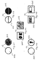
- FIGS. 2A to 2E For example, embodiments of display states 20a, 20b, 20c, 20d according to the invention are shown.
- Fig. 2A shows a simple embodiment of two display states 20a, 20b, wherein in a first display state 20a, a circular colorless surface is shown. It is understood that the shape of the display state 20a is purely illustrative in FIG Fig. 2A represented and can be configured as desired.
- the display state 20a informs the user that a sufficient battery voltage is present. When the battery 12 is almost discharged, the monitor 14 switches the display element 16 to the display state 20b, indicating that the battery 12 needs to be changed. Since the maintenance of the display state 20b consumes no power, it can be displayed indefinitely until the user perceives it and the battery 12 changes. It is understood that the display states 20a, 20b may have a reverse meaning, ie, the display state 20a is displayed when necessary battery replacement and the display state 20b is displayed at a sufficiently charged battery 12.
- FIG. 2A shown embodiment of the display states 20a, 20b can be realized for example via a bistable liquid crystal display.
- the liquid crystals of the display element 15 for the display state 20a are aligned in one direction.
- the liquid crystals are directed in a different orientation, which orientation they maintain without power supply until the next switching.
- the difference between the display states 20a, 20b can also be realized by other techniques, eg by electrochromism, an interferometric modulator display or by different reflectivities of the display states 20a, 20b.
- the display states 20a, 20b can also be realized by a display element 16 with an electromagnetic-mechanical device, for example a turning or tilting device, as in FIG Fig. 2B is shown.
- the first display state 20a comprises two semicircular plates which are held by the device of the display element 16 in a first position without power supply.
- the plates are tilted by the device in a second position. In the second position, the display state 20b is displayed, which includes two semi-circular plates of a different color.
- Fig. 12 shows another embodiment of the display states 20a, 20b in which a square display element 16 in the first display state 20a displays characters which form the word "OK". In this case, the user understands that the battery 12 is "in order", ie the battery 12 does not have to be changed.
- the second display state 20b indicates a black square, thereby informing the user of the necessary battery replacement.
- At least one display state may include a symbol. In this case, nothing is displayed in the first display state 20a, and a symbol for changing the battery is displayed in the second display state 20b.
- Fig. 2E shows an embodiment of two display states 20c, 20d, with which detailed information is displayed.
- the first display state 20c shows a first state of the battery voltage
- the second display state 20d shows a second state of the battery voltage, in which the battery 12 is compared with the first display state 20c is slightly more unloaded.
- the embodiment may include other display states not shown.
- a bistable liquid crystal display is suitable because of its high resolution because the display states 20c, 20d indicate more detailed information than the display states 20a, 20b.
- FIGS. 2A to 2E shown display states 20a, 20b, 20c, 20d can also be combined.
- FIGS. 3A and 3B show two different embodiments of a smoke detector 10 with a housing 30.
- the display element 16 must be arranged on the housing 30 of the smoke detector 10 so that the user can see the display element 16 after mounting the smoke detector 10.
- the display element 16 is disposed on a side housing surface 31.
- the display element 16 is disposed on a lower side of the housing 32, whereby the display element 16 is particularly well recognized in the assembled state. It is understood that the display element 16 arranged laterally can be circular and the display element 16 arranged on the lower housing side 32 can be made square.
Landscapes
- Physics & Mathematics (AREA)
- General Physics & Mathematics (AREA)
- Nonlinear Science (AREA)
- Crystallography & Structural Chemistry (AREA)
- Electromagnetism (AREA)
- Chemical & Material Sciences (AREA)
- Engineering & Computer Science (AREA)
- Computer Security & Cryptography (AREA)
- Optics & Photonics (AREA)
- Business, Economics & Management (AREA)
- Emergency Management (AREA)
- Fire Alarms (AREA)
- Secondary Cells (AREA)
Applications Claiming Priority (1)
| Application Number | Priority Date | Filing Date | Title |
|---|---|---|---|
| DE201210223822 DE102012223822A1 (de) | 2012-12-19 | 2012-12-19 | Rauchmelder |
Publications (1)
| Publication Number | Publication Date |
|---|---|
| EP2747047A1 true EP2747047A1 (de) | 2014-06-25 |
Family
ID=49880648
Family Applications (1)
| Application Number | Title | Priority Date | Filing Date |
|---|---|---|---|
| EP20130306697 Withdrawn EP2747047A1 (de) | 2012-12-19 | 2013-12-11 | Rauchmelder mit Anzeige des Batterieladezustands |
Country Status (3)
| Country | Link |
|---|---|
| EP (1) | EP2747047A1 (zh) |
| CN (1) | CN103901163A (zh) |
| DE (1) | DE102012223822A1 (zh) |
Cited By (1)
| Publication number | Priority date | Publication date | Assignee | Title |
|---|---|---|---|---|
| US10825333B2 (en) | 2018-01-18 | 2020-11-03 | Carrier Corporation | Electrochromic device for safety detector |
Citations (5)
| Publication number | Priority date | Publication date | Assignee | Title |
|---|---|---|---|---|
| US5646598A (en) * | 1995-05-02 | 1997-07-08 | Nickles; Aaron Michael | Smoke detector with advanced safety features |
| WO2000026761A1 (en) * | 1998-11-02 | 2000-05-11 | E Ink Corporation | Broadcast system for display devices made of electronic ink |
| US20060250261A1 (en) * | 2005-05-06 | 2006-11-09 | Henrie Ransom P | Wearable gas detector |
| EP2028631A2 (de) * | 2007-08-21 | 2009-02-25 | Hekatron Vertriebs GmbH | Rauchmelder mit Verschmutzungsüberwachung |
| EP2068288A1 (de) * | 2007-12-05 | 2009-06-10 | Gmür & Großmann GmbH | Vorrichtung und Verfahren zur Überwachung einer Funktion eines Gerätes, insbesondere eines Rauchmelders |
Family Cites Families (5)
| Publication number | Priority date | Publication date | Assignee | Title |
|---|---|---|---|---|
| US5930026A (en) * | 1996-10-25 | 1999-07-27 | Massachusetts Institute Of Technology | Nonemissive displays and piezoelectric power supplies therefor |
| JP4652716B2 (ja) * | 2004-04-21 | 2011-03-16 | ニッタン株式会社 | 煙感知器 |
| CN100403347C (zh) * | 2004-09-18 | 2008-07-16 | 清华大学深圳研究生院 | 干涉式光电感烟火灾探测方法及其装置 |
| CN101604472A (zh) * | 2009-07-09 | 2009-12-16 | 上海电器科学研究所(集团)有限公司 | 一种无线烟雾探测器 |
| GB2473237A (en) * | 2009-09-04 | 2011-03-09 | Hitachi Ltd | Wireless updates for a home automation network display |
-
2012
- 2012-12-19 DE DE201210223822 patent/DE102012223822A1/de not_active Withdrawn
-
2013
- 2013-12-11 EP EP20130306697 patent/EP2747047A1/de not_active Withdrawn
- 2013-12-19 CN CN201310757521.7A patent/CN103901163A/zh active Pending
Patent Citations (5)
| Publication number | Priority date | Publication date | Assignee | Title |
|---|---|---|---|---|
| US5646598A (en) * | 1995-05-02 | 1997-07-08 | Nickles; Aaron Michael | Smoke detector with advanced safety features |
| WO2000026761A1 (en) * | 1998-11-02 | 2000-05-11 | E Ink Corporation | Broadcast system for display devices made of electronic ink |
| US20060250261A1 (en) * | 2005-05-06 | 2006-11-09 | Henrie Ransom P | Wearable gas detector |
| EP2028631A2 (de) * | 2007-08-21 | 2009-02-25 | Hekatron Vertriebs GmbH | Rauchmelder mit Verschmutzungsüberwachung |
| EP2068288A1 (de) * | 2007-12-05 | 2009-06-10 | Gmür & Großmann GmbH | Vorrichtung und Verfahren zur Überwachung einer Funktion eines Gerätes, insbesondere eines Rauchmelders |
Non-Patent Citations (1)
| Title |
|---|
| QUALCOMM MEMS TECHNOLOGIES: "Competitive Display Technologies - mirasol", WHITE PAPER, 1 June 2009 (2009-06-01), Baltimore, Md, pages 4, XP055115335, Retrieved from the Internet <URL:http://search.proquest.com/docview/533536110> [retrieved on 20140425] * |
Cited By (1)
| Publication number | Priority date | Publication date | Assignee | Title |
|---|---|---|---|---|
| US10825333B2 (en) | 2018-01-18 | 2020-11-03 | Carrier Corporation | Electrochromic device for safety detector |
Also Published As
| Publication number | Publication date |
|---|---|
| CN103901163A (zh) | 2014-07-02 |
| DE102012223822A1 (de) | 2014-06-26 |
Similar Documents
| Publication | Publication Date | Title |
|---|---|---|
| EP2902995B1 (de) | Leuchte | |
| EP2936243B1 (de) | Elektrooptische anzeige mit einer transparenten abdeckung | |
| DE102005043310B4 (de) | Anzeigesystem insbesondere für eine industrielle Automatisierungseinrichtung | |
| EP2911141B1 (de) | Leuchte | |
| DE10126526C1 (de) | Vorrichtung zur Anzeige des Schließzustandes eines Schlosses | |
| WO2011054495A1 (de) | Vorrichtung zur anzeige von sicherheitshinweisen | |
| DE102014118421A1 (de) | Erfassungsschaltung für einen Bildschirm, Bildschirm sowie dessen Erfassungsverfahren | |
| WO1980000038A1 (en) | Monitoring device for monitoring the segments of a liquid crystal display | |
| DE102005020321A1 (de) | Sättigungsanzeige für Filter einer Dunstabzugshaube und Verfahren zur Anzeige des Sättigungsgrades für Filter einer Dunstabzugshaube | |
| WO2012051986A1 (de) | Verfahren zur darstellung der driftwerte eines luftfahrzeugs | |
| DE202016102667U1 (de) | Außenrückspiegel mit Multimodus-Anzeigefeldern | |
| EP2747047A1 (de) | Rauchmelder mit Anzeige des Batterieladezustands | |
| DE102010015774A1 (de) | Kühl- und/oder Gefriergerät | |
| WO2009047051A1 (de) | Schalter mit einer flächigen anzeige | |
| EP0987138B1 (de) | Vorrichtung und Verfahren zum Anzeigen von Piktogrammen in einem Fahrzeug | |
| DE202019105492U1 (de) | Leuchte, insbesondere Rettungszeichenleuchte oder Leuchte eines bodennahen Leitsystems | |
| EP3190351A1 (de) | Heizungsdisplay | |
| DE4410800A1 (de) | Drehanzeigeeinrichtung für Pumpen | |
| EP2048677A9 (de) | Bedieneinrichtung zur Bedienung einer Werkzeugmaschine, Produktionsmaschine und/oder eines Roboters | |
| EP3360016B1 (de) | Feldgerät mit einem durch ein betätigungselement aktivierbares funkmodul | |
| DE102007022002A1 (de) | Anzeigeeinrichtung für ein Schaltgerät | |
| EP0109473B1 (de) | Optisches Anzeigeelement | |
| DE102020121343B4 (de) | Anzeigeeinrichtung mit einem E-Paper-Display und Fahrzeug mit zumindest einer Anzeigeeinrichtung | |
| EP3462433B1 (de) | Sicherheits- oder rettungszeichenleuchte und sicherheitsbeleuchtungsanlage | |
| EP2815475A1 (de) | Schaltvorrichtung mit externem modul |
Legal Events
| Date | Code | Title | Description |
|---|---|---|---|
| PUAI | Public reference made under article 153(3) epc to a published international application that has entered the european phase |
Free format text: ORIGINAL CODE: 0009012 |
|
| 17P | Request for examination filed |
Effective date: 20131211 |
|
| AK | Designated contracting states |
Kind code of ref document: A1 Designated state(s): AL AT BE BG CH CY CZ DE DK EE ES FI FR GB GR HR HU IE IS IT LI LT LU LV MC MK MT NL NO PL PT RO RS SE SI SK SM TR |
|
| AX | Request for extension of the european patent |
Extension state: BA ME |
|
| STAA | Information on the status of an ep patent application or granted ep patent |
Free format text: STATUS: THE APPLICATION IS DEEMED TO BE WITHDRAWN |
|
| 18D | Application deemed to be withdrawn |
Effective date: 20150106 |