EP2746715B2 - Container for missile - Google Patents
Container for missile Download PDFInfo
- Publication number
- EP2746715B2 EP2746715B2 EP13005636.9A EP13005636A EP2746715B2 EP 2746715 B2 EP2746715 B2 EP 2746715B2 EP 13005636 A EP13005636 A EP 13005636A EP 2746715 B2 EP2746715 B2 EP 2746715B2
- Authority
- EP
- European Patent Office
- Prior art keywords
- container
- roof
- missile
- movement
- canister
- Prior art date
- Legal status (The legal status is an assumption and is not a legal conclusion. Google has not performed a legal analysis and makes no representation as to the accuracy of the status listed.)
- Active
Links
- 238000003860 storage Methods 0.000 claims description 56
- 230000008878 coupling Effects 0.000 description 20
- 238000010168 coupling process Methods 0.000 description 20
- 238000005859 coupling reaction Methods 0.000 description 20
- XLYOFNOQVPJJNP-UHFFFAOYSA-N water Substances O XLYOFNOQVPJJNP-UHFFFAOYSA-N 0.000 description 9
- 239000004576 sand Substances 0.000 description 8
- 230000008901 benefit Effects 0.000 description 7
- 230000005484 gravity Effects 0.000 description 7
- 239000007789 gas Substances 0.000 description 6
- 238000000034 method Methods 0.000 description 6
- 230000006378 damage Effects 0.000 description 5
- 238000007789 sealing Methods 0.000 description 4
- 238000012360 testing method Methods 0.000 description 4
- 230000008602 contraction Effects 0.000 description 3
- 238000012423 maintenance Methods 0.000 description 3
- 230000008569 process Effects 0.000 description 3
- 230000007704 transition Effects 0.000 description 3
- 238000013459 approach Methods 0.000 description 2
- 238000013461 design Methods 0.000 description 2
- 239000000428 dust Substances 0.000 description 2
- 230000001681 protective effect Effects 0.000 description 2
- 239000007787 solid Substances 0.000 description 2
- 230000001133 acceleration Effects 0.000 description 1
- 230000009471 action Effects 0.000 description 1
- 230000004913 activation Effects 0.000 description 1
- 230000009286 beneficial effect Effects 0.000 description 1
- 230000008859 change Effects 0.000 description 1
- 230000001427 coherent effect Effects 0.000 description 1
- 238000010276 construction Methods 0.000 description 1
- 238000011109 contamination Methods 0.000 description 1
- 230000007123 defense Effects 0.000 description 1
- 238000005474 detonation Methods 0.000 description 1
- 238000007598 dipping method Methods 0.000 description 1
- 230000000694 effects Effects 0.000 description 1
- 238000010304 firing Methods 0.000 description 1
- 230000006870 function Effects 0.000 description 1
- 238000002955 isolation Methods 0.000 description 1
- 238000004519 manufacturing process Methods 0.000 description 1
- 230000035515 penetration Effects 0.000 description 1
- 238000003825 pressing Methods 0.000 description 1
- 230000008439 repair process Effects 0.000 description 1
- 239000013589 supplement Substances 0.000 description 1
- 238000013519 translation Methods 0.000 description 1
Images


Classifications
-
- F—MECHANICAL ENGINEERING; LIGHTING; HEATING; WEAPONS; BLASTING
- F41—WEAPONS
- F41F—APPARATUS FOR LAUNCHING PROJECTILES OR MISSILES FROM BARRELS, e.g. CANNONS; LAUNCHERS FOR ROCKETS OR TORPEDOES; HARPOON GUNS
- F41F3/00—Rocket or torpedo launchers
- F41F3/04—Rocket or torpedo launchers for rockets
- F41F3/042—Rocket or torpedo launchers for rockets the launching apparatus being used also as a transport container for the rocket
-
- F—MECHANICAL ENGINEERING; LIGHTING; HEATING; WEAPONS; BLASTING
- F41—WEAPONS
- F41A—FUNCTIONAL FEATURES OR DETAILS COMMON TO BOTH SMALLARMS AND ORDNANCE, e.g. CANNONS; MOUNTINGS FOR SMALLARMS OR ORDNANCE
- F41A23/00—Gun mountings, e.g. on vehicles; Disposition of guns on vehicles
- F41A23/20—Gun mountings, e.g. on vehicles; Disposition of guns on vehicles for disappearing guns
-
- F—MECHANICAL ENGINEERING; LIGHTING; HEATING; WEAPONS; BLASTING
- F41—WEAPONS
- F41F—APPARATUS FOR LAUNCHING PROJECTILES OR MISSILES FROM BARRELS, e.g. CANNONS; LAUNCHERS FOR ROCKETS OR TORPEDOES; HARPOON GUNS
- F41F3/00—Rocket or torpedo launchers
- F41F3/04—Rocket or torpedo launchers for rockets
- F41F3/077—Doors or covers for launching tubes
-
- B—PERFORMING OPERATIONS; TRANSPORTING
- B65—CONVEYING; PACKING; STORING; HANDLING THIN OR FILAMENTARY MATERIAL
- B65D—CONTAINERS FOR STORAGE OR TRANSPORT OF ARTICLES OR MATERIALS, e.g. BAGS, BARRELS, BOTTLES, BOXES, CANS, CARTONS, CRATES, DRUMS, JARS, TANKS, HOPPERS, FORWARDING CONTAINERS; ACCESSORIES, CLOSURES, OR FITTINGS THEREFOR; PACKAGING ELEMENTS; PACKAGES
- B65D88/00—Large containers
- B65D88/02—Large containers rigid
- B65D88/12—Large containers rigid specially adapted for transport
- B65D88/122—Large containers rigid specially adapted for transport with access from above
- B65D88/124—Large containers rigid specially adapted for transport with access from above closable top
- B65D88/126—Large containers rigid specially adapted for transport with access from above closable top by rigid element, e.g. lid
Definitions
- the invention relates to a missile container with a container housing, at least one canister arranged therein in the storage position for carrying a missile and a movement means for moving the canister from a storage position into an operating position.
- a missile of the type mentioned with a corresponding container and carrier is made GB 1 294 006 A known.
- So-called surface-to-air missiles are known for defense tasks, which are stored in a canister and fired from the canister, either vertically or at an angle upwards. When a missile is launched from its canister, a hot exhaust gas jet is created, in the vicinity of which there must be no sensitive components if their destruction is to be avoided.
- Missiles are usually stored for long periods of time and are stored in the container housing of the missile container for this purpose. Even during transport, they are arranged within the container housing of the missile container and held tightly closed therein. In order to be able to be put into combat readiness, the missiles and their canisters must be removed from the container housing and positioned accordingly so that they can take off without causing damage from their exhaust gas jet.
- the container housing should be closable in such a way that the contents are at least splash-proof so that the missile container can be transported through rain, wind and snow without internal elements suffering.
- the missile container must remain in combat readiness or on alert for a long time.
- the missile container may be exposed to the elements, be it rain, snow or wind, or even dust or desert sand.
- the container housing can also be closed in the operating position of the canister. At least parts of the interior of the container housing should be protected by a container roof.
- the object is achieved by a missile container according to claim 1.
- This object is achieved by a missile container of the type mentioned, in which, according to the invention, in the operating position, the canister is at least partially held by the moving means outside the container housing and the container roof is closed to shield a container interior from the outside.
- Devices arranged in the interior of the container can be protected from external weather conditions and the missile container can be kept in alert or combat readiness for a longer period of time.
- the operating position of the canister can be a combat position from which a missile held in the missile is regularly launched. However, the operating position can be a maintenance or repair position in which the canister is held for servicing or repairing the missile or the canister.
- the moving means is anchored in a structurally fixed manner inside the container housing, so that it has to be passed through the container housing in order to hold the canister outside the container housing.
- this passage can take place through one or more of the container side walls, according to the invention it is passed through the container roof.
- the container housing there is therefore expediently a recess through which the movement means is passed in the operating position. If the movement means is arranged outside this recess in the storage position, the recess is expediently closed in order to keep the container housing tight in the storage position.
- the missile is expediently a rocket missile, that is to say a missile with a rocket engine, in particular a surface-to-air missile, a surface-to-surface missile or a sea-based missile.
- the missile is an unmanned missile and expediently equipped with a warhead that can accommodate a detonation charge.
- the invention is not limited to missiles and a container for a missile. Instead of a missile, another object can be moved.
- the canister serves to carry the missile and also expediently to store it in the closed missile container and advantageously also to hold it when it is launched.
- the missile is thus expediently launched from the canister and the canister is prepared for such a launch.
- the storage position is a position of the canister in which the missile or the canister is stored over a storage period, for example over several months, in particular over several years.
- the storage position is a position in which the missile or the canister with the missile is stored for a longer period of time. It can also be a transport position in which the canister and the missile are transported on or in a vehicle.
- the operating position is a position in which the canister is operating. Such an operation can be a launching of the missile from the canister, a maintenance operation in which the canister is serviced or repaired, a test operation, for example for testing sensors of the canister or the missile, or another suitable operation of the canister.
- the operating position is a different position than the storage position, the canister expediently being pivoted relative to the storage position in the operating position.
- the container housing is expediently a housing that is closed around the missile. It expediently has the dimensions of a 20-foot ISO transport container. As a result, the missile container can be combined and used with typical logistic systems for containers. It is also advantageous if the container housing can be closed in a splash-proof manner, so that the interior of the container housing is protected from bad weather influences, such as rain or storms. Such weather protection can be achieved if the container housing is designed externally in the same way as a standard transport container. In addition, easy and inconspicuous transport is possible.
- the container housing is expediently equipped with solid side walls and an access door. In addition, a control panel area with a protective cover, for example a protective flap, and in particular a connection for supply lines is advantageous.
- the missile container or its container housing is expediently closed, as described above.
- the missile container is in a state of alert or readiness for activation over a longer period of time in which the canister is arranged in the combat position.
- the container housing is also closed when the missile container is ready for action or when the canister is in combat position.
- splash resistance in particular from all sides, is advantageous here too.
- a plurality of canisters each for carrying at least one missile are expediently arranged on the moving means.
- Four or eight canisters per canister unit which are used as a unit, e.g. firmly joined together, attached to the means of movement.
- the moving means is used to move the canister from the storage position into the operating position and can for this purpose comprise a coupling gear.
- the movement means is expediently prepared to carry out a movement which has more degrees of freedom than a simple rotation about a simple rotation axis.
- a higher degree of freedom is not necessarily to be understood as a higher dimensionality of the movement, since a one-dimensional movement is sufficient. Rather, a more complex movement path than a straight line or a simple circular or elliptical path should be made possible, for example a combination of two circular paths with different centers.
- the container housing advantageously comprises a roof unit through which a roof opening of the container housing can be opened and closed again.
- the roof unit is movably supported by the rest of the container housing, so that it can close the roof opening by a pivoting movement, a translational movement or a combination movement.
- the roof unit can comprise several roof elements, for example two roof wings or other elements that can be moved symmetrically to one another. It is useful for a good sealing of the container housing if the roof unit has two roof wings which partially cover one another in the closed position. A seal that seals the container interior from the outside can be arranged between the two roof wings.
- the roof unit and the movement means are expediently coordinated with one another in such a way that the roof unit can be closed both when the movement means is in the storage position and when the movement means is in the operating position.
- the interior of the container In the closed state of the roof unit, the interior of the container is shielded from the outside, the entire interior of the container housing expediently being shielded from the outside and closed.
- there can be further openings in the container housing for example a door for entering the container interior, a window, another roof flap or several of these elements or other elements.
- the shielding of the interior of the container from the outside can be understood to mean that all of these elements are closed.
- the container roof has a passage through which the movement means protrudes in the operating position.
- the passage can be a recess that can be closed by a roof flap or another closure element.
- the roof flap or the other element is expediently different from the roof unit, such as a roof wing, and is present in addition to it. If the moving means is not passed through the leadthrough but is positioned elsewhere, the leadthrough should be closed or at least be able to be closed so that the missile container can also be adequately closed in the storage position of the canister. It is therefore useful if the bushing is closed when the moving means is moved out of the bushing, for example by a roof flap.
- the term roof flap like the term roof wing, implies a rotary opening or closing movement. However, these terms should not be reduced to such a closing movement, so that an element that opens or closes purely translationally or in a combination movement is also referred to as a roof flap or roof wing.
- the bushing is advantageously arranged directly next to an area of the roof opening that can be closed by a roof wing.
- This roof opening area and the implementation are thus directly adjacent to one another, so that the implementation and the roof opening form a coherent opening.
- the moving means can move out of the roof opening into the bushing and thus move out of this area of the roof opening, which is closed by the roof wing.
- the roof flap is advantageously designed in such a way that it closes automatically when the movement means is moved out of the passage.
- This closing can be motor-driven, spring-driven or in some other way.
- a spring-driven closing is particularly easy, inexpensive and reliable to achieve.
- the roof flap can also be held in a simple manner if it and the movement means are arranged and designed in relation to one another in such a way that the movement means presses the roof flap open by moving it into the operating position.
- the movement means can press the roof flap open against a spring force which, when the movement means is moved out of the passage, presses the roof flap back into its closed position.
- the movement means completely fills the passage, so that the interior of the container is closed with a closed roof element and in the position of the movement means in the operating position, ie the passage is also closed.
- the roof unit has at least one roof element, for example in the form of a roof wing, which rests on the container housing.
- the roof opening can be opened in a simple manner by moving the roof element, referred to in the following simply as the roof wing, upwards.
- the roof wing can expediently be lifted completely upwards from the container housing. This can be understood to mean that the roof wing can be lifted off the container housing on all of its side edges, for example its four side edges.
- the ability to be lifted upwards is expediently designed in such a way that there is no need to mount the roof wing in the container housing. Sealing of the container housing can hereby be facilitated, since a mounting of the roof wing in the container housing may not be easily sealable.
- the lift-off is expediently motor-driven.
- the missile container expediently comprises an opening means for opening the roof wing, in particular by lifting the roof wing completely from the container roof.
- a single roof wing can be sufficient to close the roof opening, and two or more roof wings can just as easily be present for this task.
- a good seal of the container housing to the outside is useful if the roof wing engages around the upper side edge of the container side wall from above and from the side.
- the container side wall is part of the container housing and expediently protrudes vertically upwards. By reaching around the upper side edge from above and from the side, a seal of the container roof that is accessible from above can be dispensed with, so that water can flow off the side of the container roof without touching such a sealing point.
- the missile container has an opening means for opening the roof wing by pivoting the roof wing upwards and to the side.
- the wing expediently tilts outwards so that, for example, sand slides outwards on the wing without being able to touch the outside of the container.
- a simple construction of the opening means for opening the roof wing is beneficial if the roof wing is mounted pivotably in a single axis of rotation.
- the axis of rotation is expediently arranged in the interior of the container, that is to say encompassed by the container housing.
- the movable mounting of the roof wing that is to say a bearing, a hinge or the like, is also positioned within the container interior.
- a lateral movement of the roof wing when opening can easily be achieved if the axis of rotation is arranged by more than 5% of the container width below the upper edge of the container on which the roof wing rests.
- the axis of rotation is arranged by more than 10%, expediently even by more than 25% of the container width below the upper edge of the container.
- the axis of rotation is less than 20%, in particular less than 10% of the container width away from the lateral one Container wall is arranged around which the roof wing pivots.
- a lateral sealing surface of the container housing and / or the roof wing can be sealed particularly easily and reliably if the roof wing approaches the upper side edge of the container side wall rather horizontally when it is closed.
- the missile container has an opening means for moving the roof wing by pivoting the roof wing in such a way that the outside of the roof wing when closing with a push angle of less than 20 °, in particular less than 10 °, to the horizontal on the container wall is moved.
- the roof wing lifts up on its inside more upwards than to the side.
- the roof wing has an inner cover which, when the roof wing is open, covers the upper side edge of the container housing so that it is protected. This can also protect a seal on the top edge of the side or on the top edge of the side. At least 50% of the total length of the top edge is covered.
- the opening means is force-free both in the open and in the closed state of the roof wing. This can easily be achieved if the roof wing is supported on a support means in the open state, so that the opening means is free of forces and the roof wing remains in a secure opening position.
- the support can take place directly or indirectly, for example via one or more elements of the opening means.
- the support means can be an element of the container housing, for example a container side wall.
- the invention in its general form is directed to a missile canister having a canister housing, a missile stored therein, and a canister roof.
- the missile is held in its launch position at least partially outside the container housing and the container roof is closed and shields a container interior from the outside.
- a method for operating a missile container with a container housing and at least one canister stored therein for carrying a missile, in which the canister is moved from a storage position into an operating position by a movement means.
- a roof wing of the container housing is opened and a roof opening is thereby released.
- the canister is moved from the storage position into an operating position and through the roof opening. Further advantageously, the roof wing is closed again in the operating position of the canister, whereby the roof opening is closed.
- the container housing advantageously achieves an at least splash-proof state, as a result of which elements in the container interior are also well protected in the operating position.
- the movement means when moving into the operating position, press on a closure means of the container roof, which thereby releases a passage in the container roof.
- the closure means can be opened without its own motorized drive, so that it is easy to manufacture.
- the closure means closes in a spring-driven manner when the movement means is moved out of the operating position and closes the passage.
- a good protection of the container interior from contamination can be achieved if the roof wing pivots to the side when it moves out of its closed position and immediately moves to the side so that water on the roof wing flows off to the side and falls down at a distance from the container side wall. Water, sand or dirt can be reliably thrown off the tank roof or roof wing without getting into the tank interior.
- a moving means from a storage position to an operating position at least partially through the opened container roof .
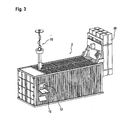
- Fig. 1 shows a missile container 2 with a closed container housing 4.
- the container housing 4 has the dimensions of a standard 20-foot container and also contains the standardized mounting recesses and fastening means for fastening to other 20-foot containers and corresponding loading devices.
- the container housing 4 comprises an access door 6 for entering the interior of the container, which door is designed like conventional container doors.
- the missile container 2 also corresponds in shape and design to a 20-foot ISO transport container.
- the missile container 2 comprises an interface 8 for connection to a power supply, with one or more further connections also being optionally possible, for example a data connection.
- the missile container 2 further comprises a cover 10 through which a display and input means 12 (see FIG Fig. 3 ) is protected from the outside.
- the container housing 4 On its upper side, the container housing 4 has a container roof 14 with two roof wings 16 which are symmetrical to one another and which each extend over more than half the length of the missile container 2. At the rear end of the container roof 14, two roof flaps 18 are arranged, which are shown in FIG Fig. 2 are shown enlarged.
- Fig. 2 shows a section of the rear container roof 14 of the missile container 2.
- the two roof flaps 18 arranged at the rear end of the container roof 14 each adjoin a roof wing 16 and, like the roof wing 16, can be opened so that a roof opening released by the roof wings 16 is adjacent the roof opening released by the roof flaps 18 is adjacent, so that a single large roof opening is created.
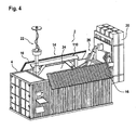
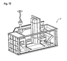
- Fig. 3 shows the missile container 2 also in a closed state, the container housing 4 is therefore closed, but canisters 20 and missiles stored therein are outside the container housing 4 held and arranged in an operating position.
- An antenna 22 is also folded out and is located outside the container housing 4.
- the cover 10 is open so that a display and input means 12 located behind it is accessible.
- the missile container 2 is closed to the extent that the container interior, which is enclosed by the container housing 4, is largely protected from the effects of the weather.
- the container housing 4 is rainproof and splash-proof as well as sand and dustproof, so that elements in the interior of the container are protected from these influences.
- the in Fig. 1 The shown state of the missile container 2 is a storage and transport state in which the container housing 4 is firmly closed and protects the device in the container interior. Opposite is the in Fig. 3
- the state shown is an operating state of the missile container 2, in this case a combat state.
- the missile container 2 can also remain in this state for a long time without the device in the container interior being exposed to the corresponding external influences, for example in the case of rain or strong wind with drifting sand.
- the canisters 20 are aligned vertically with the canister front side up, so that the missiles stored in the canisters 20 emerge from the corresponding canister 20 through the rocket thrust when they start their rocket engine and take off vertically upwards.
- the canisters 20 are arranged outside the container housing 4 and are also positioned at an appropriate height above the ground.
- the height of the lower edge of the canister 20 is at least 80 cm, in particular at least 1 m.
- the rear wall of the container which is not shown in the figures, is always closed so that gases from the hot exhaust gas jet do not penetrate into the interior of the container housing 4.
- the missile container 2 can be used universally. It can be used standing on a solid floor as well as on a truck. Use on a ship or other objects to be protected, for example an oil platform, is also easily possible.
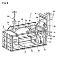
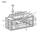
- Fig. 4 shows the missile container 2 in an operating position of the canister 20, but with the container roof 14 open.
- the two roof flaps 16 are pivoted upwards and to the side and thus reveal a roof opening 24 of the container housing 4.
- the canister 20 can be moved into and out of the container interior through this roof opening 24.
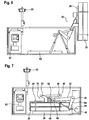
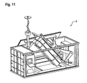
- the missile container 2 comprises a movement means 26, which is represented by the sectional view of the missile container 2 in Fig. 5 is shown more clearly.
- Fig. 5 shows the missile container 2 from Fig. 4 in a representation in which a side wall of the container housing 4 is cut and thus shown open. For the sake of a better view, one of the roof wings 16 has been omitted from the illustration. In addition, only four of the eight canisters are attached to a holding unit 28 of the movement means 26, which in the in Fig. 3 shown condition are used. The other four canisters 20 are arranged in the storage position in the interior of the container and rest on a base 30 of the missile container 2. Fig. 5 shows a loading state of the missile container 2 in which the stored canisters 20 have already been brought into the missile container 2 but are not yet attached to the means of movement 26.
- the movement means 26 comprises a kinematic coupling gear, which in this embodiment has two mirror-symmetrical units on both longitudinal sides of the container.
- a container side wall represents the stationary part of the linkage.
- the holding unit 28 forms the movable part of the linkage, which is connected to or forms the two rockers or links of the two units of the linkage.
- the two units of the movement means 26 are each designed as coupling gears 46 in the form of a four-link kinematic chain.
- the container housing 4 serves as a housing member or a stationary housing element.
- the holding unit 28 serves both units as a coupling or coupling member or operating member.
- the coupling gear 46 comprises a lever linkage with four pivot points fixed to the housing.
- Each coupling gear 46 comprises two movable members 32, 34 in the form of rigid elements, for example rods.
- Each of the movable members 32, 34 is rotatably connected to the housing member or the container housing 4 at a pivot point 36, 38 which is fixed to the housing, but is otherwise fixedly connected.
- the movable members 32, 34 are connected to the operating member or the holding unit 28 via movable pivot points 40, 42.
- the pivot points 40, 42 are rigidly mounted relative to the coupling member or the holding unit 28.
- Parts of the coupling gears 46 are located next to the holding unit 28.
- This embodiment allows narrow elements, so that a very wide holding unit 28 can be used or the arrangement of moving means 26 and canisters 20 can be made particularly compact.
- the coupling gear 46 is in the Figures 6 and 7 shown from the side so that the front unit hides the mirror-symmetrical rear unit.
- Fig. 6 shows the canister 20 here in the same position as Fig. 5 , being in contrast to Fig. 5 however, all canisters 20 are arranged on the moving means 26.
- Fig. 7 shows the moving means 26 and the canisters 20 in the storage position. The canisters 20 are placed on the base 30, for example inserted there, and the moving means 26 is attached to the canisters 20.
- the Figures 7 and 8th show the canister 20 or the moving means 26 in the storage position.
- the canisters 20 are at least positively connected to the container housing 4, for example via the base 30, that a horizontal movement of the canisters 20 relative to the container housing 4 is blocked.
- the moving means 26 or its holding unit 28 is lowered from above onto the stationary canisters 20 and connected to them, so that the canisters 20 are rigidly connected to the holding unit 28 in all directions.
- FIG. 8 A first part of the movement is through the Figures 8 and 9 shown.
- the canisters 20 are lifted up to a certain extent from the base 30. This is done by a movement motor 48 rotating the movable member 32 about the pivot point 36.
- Fig. 8 it can be seen that the two units or coupling gears 46 are opposite one another in the container housing 4, so that their two pivot points 36 form a fixed axis 50 around which the movable member 32 of both coupling gears 46 is rotated.
- a further fixed axis 52 is shown, which connects the two pivot points 38 fixed to the housing with one another.
- the two movable members 34 of the two coupling gears 46 rotate about this fixed axis 52.
- Both fixed axes 50, 52 are shown in FIG Fig. 8 shown with long dashed lines.
- pivot point 40 As a result of the rotation of the movable members 32 of the coupling gears 46, their movable pivot point 40 also rotates about the pivot point 36 fixed to the housing.
- the two movable pivot points 40 form a pivot axis 54 which runs through the two movable pivot points 40 and which is shown in FIG Fig. 8 is shown in phantom.
- Another pivot axis 56 which runs through the pivot points 42 of the movable members 34 of the two coupling gears 46, is also shown in phantom. This pivot axis 56 rotates in a circle about the fixed axis 52.
- the degree of freedom of movement of the holding unit 28 or the canister 20 with respect to the container structure or the stationary container housing 4 is realized only with swivel joints.
- Each coupling gear 46 thus generates the curvilinear movement from merely pivoting movements about two fixed axes 50, 52.
- the movement of the movement means 26 is generated by two movement motors 48, each coupling gear 46 being assigned a movement motor 48.
- Each movement motor 48 comprises two motor units 58, 60, both of which are designed as push rods.
- the two motor units 58, 60 are hydraulic cylinders which are connected to a hydraulic pump and controlled by a control means 62.
- the hydraulic cylinders act directly on the main support member 32 of the coupling gear 46.
- the drive power is transmitted via four hydraulic cylinders, two on each side. In the event of a hydraulic leak, the holding unit 28 can thus be stopped in any position in order to avoid consequential damage.
- the two motor units 58, 60 each engage a single lever 64 of the linkage 46, which is rigidly connected to one of the movable members 32, 34, in the embodiment shown in the figures, the movable member 32.
- the drive for moving the movement means 26 acts only on one gear element, in this case the movable member 32.
- Both motor units 58, 60 generate the movement of the movement means 26 by means of a change in length, that is to say a contraction and expansion.
- both motor units 58, 60 can generate the motive force exclusively through expansion, or at least one of the motor units 58, 60 is additionally prepared for the application of motive force to the moving means 26 through contraction. In the present case, this is the case with the motor unit 60.
- each movement motor 48 comprises exclusively variable-length motor units 58, 60 which are each pivotable about a fixed axis 66, 68.
- These two fixed axes 66, 68 are in Fig. 8 shown briefly in dashed lines and connect the corresponding motor units 58 and 60 of the two movement motors 48.
- a four-sided to the four fixed axes 50, 52, 66, 68 here comprises a maximum extent that is less than half a canister length.
- the canisters 20 By driving the two movement motors 48, the canisters 20 move from the in Fig. 8 bearing position shown translationally away from the base 30, in this exemplary embodiment vertically upwards.
- Such a translational movement has the advantage that holding members 70, which ensure that the canisters 20 are fixed to the base 30, can be removed from the base 30 or the canisters 20 without tilting.
- a holding member 70 engages in a recess in the base 30, so the upward translational movement causes the holding member 70 to be removed from the corresponding recess Recess drawn.
- FIG. 14 and 15 This translational movement is shown in Figures 14 and 15 by the beginning of the movement paths 72, 74, which are shown in the Figures 14 and 15 are shown dotted.
- the movement path 72 of the front lower end of the canister 20 and the movement path 74 of the rear lower end of the canister 20 are shown. From the front movement path 72 it can be seen that the front of the canister is moved substantially vertically upwards, with an angular deviation of up to 20 °, in particular up to 10 °, is harmless and is also to be understood conceptually under the vertical translation in this context. It can be seen from the rear movement path 74 that the rear end of the canister 20 is also initially lifted upwards, so that the translational movement results from the upwards lifting of the front and rear ends of the canister 20. How out Fig.
- the first part of the two movement paths 72, 74 is parallel to one another, from which the translational movement, in this exemplary embodiment essentially vertically upwards, results.
- This translational part of the movement runs over at least 110 cm, in particular over at least 15 cm.
- the in Fig. 15 Shown translational part of the movement about 25 cm.
- the movement of the rear part of the canister 20 after the translational phase makes a sharp bend of at least 60 °, in the embodiment shown even 90 °.
- the translational phase changes into a rotation phase of the canister 20.
- the rear part of the canister 20 in the storage position moves essentially horizontally.
- the transition between vertical and horizontal movement is shorter than the translational movement, only a few centimeters in the embodiment shown.
- the transition from the translational movement phase to the rotational movement phase of the canister 20 takes place very sharply, as from the movement paths 72, 74 Fig. 15 you can see.
- This sharp transition is advantageous because a very precise translational movement can initially be used to detach the canister 20 from the container housing 4, for example from the base 30.
- the rapid onset of the rotational movement phase leads to a relatively low volume requirement for the overall movement of the canister 20 from its storage position to its operating position.
- This type of movement not only can the movement be kept compact, but a relatively large amount of space in the container housing 4 can also be used for other objects, for example switch cabinets 76, so that a compact design of the missile container 2 is possible overall.
- the movement of the canister 20 vertically upwards is made possible by the position of the fixed axis 50 relative to the pivot axis 54 and the fixed axis 52 relative to the pivot axis 56.
- the two pairs of axes of the fixed axis 50 and the pivot axis 54 or the fixed axis 52 and the pivot axis 56 each form a plane that is arranged substantially horizontally.
- the first part of the movement paths 72, 74 takes place essentially vertically upwards by raising the two pivot axes 54, 56.
- the translational movement can be achieved through the extensive parallelism of these two planes in the storage position.
- Another criterion of the movement paths 72, 74 which leads to a low space requirement of the movement paths 72, 74 or the canister 20 in the course of its movement, is that the geometric center of gravity 78 of the canister 20 is not only during the translational phase of the movement but also moved vertically upwards during the first part of the rotational movement. This is in the Figures 14 and 15 shown by the dash-dotted line of movement of the center of gravity 78. This trajectory of the center of gravity 78 remains essentially vertical until the center of gravity 78 has left the container housing 4. Only then does a significant pivoting of this center of gravity path from the straight line and especially from the vertical take place.
- the translational movement phase of the canister is followed by a pivoting phase, during which the canister 20 is pivoted strongly upward with a relatively small movement, namely by 90 °.
- a pivoting phase during which the canister 20 is pivoted strongly upward with a relatively small movement, namely by 90 °.
- the strong pivoting movement must also be carried out, which begins relatively quickly after the translational movement phase and thus the Movement motors 48 opposed a certain inertia.
- the greatest expenditure of force for the movement motors 48 has to be made during the first 90 ° pivoting of the canisters 20.
- the motor units 58, 60 are arranged with respect to one another in such a way that during this phase they engage opposite one another on the lever 64 and can thereby apply forces particularly well. This also applies in particular because both push rods are extended relatively briefly in this phase and the motor units 58, 60 are thereby still in their most powerful pushing or pulling phase.
- the motor unit 58 acts here by pressure and the motor unit 60 by pulling, with the motor unit 60 also being prepared for the application of force by thrust, as in the movement phase shown in FIG Fig. 13 is shown, can be seen. From a rotation of about 180 °, the motor unit 60 also acts by pressure on the lever 64 and thus brings the canisters 20 into their operating position, which is shown in FIG Fig. 5 is shown.
- the motor unit 60 acts on tension, whereas the motor unit 58, which is only designed to act on pressure, is moved passively with it.
- the fact that only one of the motor units 58, 60 brings the motor force into the coupling gear 46 is not critical, since the load of the canister 20 and the holding unit 28 only needs to be increased slightly in order to reach the highest position, from which onwards the backward movement no longer has to exert a force pulling the canister 20.
- the illustrated storage position of the canister 20 or the movement means 26, the movement motors 48 can remain force-free. In the storage position, this can be easily seen, since the moving means 26 is placed on the container bottom or the base 30.
- the movement means 26 is also stored in the operating position, in this exemplary embodiment on a storage surface 82, for example the top of the rear container wall, as shown in FIG Fig. 5 can be seen.
- the underside of a support arm 80 of the movement means 26 or the holding unit 28 lies on the upper side (see FIG Fig. 13 ) the rear container wall. The weight of the canister 20 and the holding unit 28 holds the moving means 26 and the canister 20 in the operating position.
- the movement motor 48 can be held without force and the canisters 20 remain securely in their operating position.
- the two inherently stable positions of the storage position and the operating position have the advantage that an operator can safely enter the container housing 4 and the movement motors 48 can be switched off without the danger of the moving means 26 or the canisters 20.
- the hydraulic lines are also depressurized and therefore safe.
- the canisters 20 rotate through 270 °. You are not only lifted from the horizontal to the vertical position, but also rotated by 180 °.
- This form of movement has the advantage that it is very compact and therefore only requires a small amount of space both inside and outside the container housing 4. It also has the advantage that the rear of the canister is arranged facing away from the coupling gears 46 or the movement motors 48. This side is particularly easy to access, so that this side is easily and quickly accessible when entering the container housing 4 or the container through the access door 6. Since interfaces are usually located more at the rear end of the canister 20, these can easily be connected.
- the missile container 2 To operate the missile container 2, it must be loaded with an operating item, for example a canister 20.
- an operating item for example a canister 20.
- other operational items can generally also be used for operating the missile container 2.
- the missile container 2 and its operation are not limited to one or more canisters 20, but other operating objects can also be used, for example other mountings for one or more missiles or other objects.
- an operator can first open the cover 10 and activate the control means 62 via the input means 12. The operator then opens the container roof 14 - expediently via the input means 12 and control means 62 - by opening the roof wing 16.
- the operator can now move the movement means 26 in this way that a shelf for the canister 20, in the illustrated embodiment the base 30, becomes free in order to place the canister 20 thereon.
- the moving means 26 from its in the Figures 7 and 8th are moved away storage position shown, for example into the operating position shown in the Figures 5 and 6 is shown.
- Canisters 20 are not yet attached to holding unit 28 at this point in time.
- a canister 20 can now be lowered into the container housing 4 from above, for example with a crane.
- the roof opening 24 is open so wide that the canister 20 can be lowered vertically from above onto the shelf in the container housing 4, for example the base 30.
- the operator can open the access door 6 of the container housing 4 and enter the interior of the missile container 2.
- the operator can guide the canisters 20 attached to crane ropes by hand so that the holding members 70 are positively connected between the canister 20 and the base 30 and the canister 20 is thus correctly positioned in the storage position.
- the canister 20, to which the holding unit 28 is prepared to be carried is inserted into the container housing 4.
- another suitable storage unit can also be used.
- the loading position in which one or more canisters are stored in the container housing 4 for connection to the holding unit 28 can also differ from the storage position. In the embodiment shown in the figures, however, the storage position is identical to the loading position.
- the control means 62 expediently comprises one or more control programs as well as electronic elements, such as a processor and data memory, which are necessary for running the control programs.
- the holding unit 28 is made, as by the movement paths 72, 74 Fig. 15 shown, brought translationally to the lying canister 20, in the illustrated embodiment, translationally perpendicular from above. In this way, fastening means on the canister 20 and / or the holding unit 28 can be reliably brought into a holding position in which the canister 20 is firmly connected to the holding means 28.
- the holding means can be a latching means which, when the holding unit 28 moves towards the canister 20, latches in such a way that the canister 20 is firmly connected to the holding unit 28.
- the operator can now move the moving means 26 into a loading position or - as is shown by way of example in the figures - into the operating position.
- the holding unit 28 is now only with some of the canisters which the holding unit 28 is prepared to carry. This is for example in Fig. 5 shown.
- FIG. 5 Another canister 20 or a further package with several canisters 20 can now be stored in the container housing 4 as described above. This situation is exactly in Fig. 5 shown.
- the holding unit 28 can now be lowered again onto the stored canisters 20 and fastened with them, so that the holding unit 28 is now completely equipped.
- the missile container 2 is completely loaded and the loading process can be completed by the operator closing the container roof 14 again and protecting the display and input means 12 by the cover 10.
- the missile container 2 is now ready for transport or longer storage.
- the missile container 2 To make the missile container 2 operational, for example combat readiness, it is expediently brought to an operating location, for example a building to be protected, an oil platform, a ship, a truck or a floor; the possible uses are very diverse .
- An operator can now open the cover 10 and activate the control means 62 via the input means 12, expediently with a protected access code.
- the container roof 14 is opened by pivoting the roof wing 16, the antenna 22 is folded out and the means of movement is brought from the storage position into the operating position, for example as described above.
- the canisters 20 or the missiles stored therein are now ready for operation, for example a take-off.
- a maintenance operation of the missile container 2 can also be carried out easily and quickly. For example, an operator can enter the interior of the container housing 4 through the access door 6 and inspect the canisters 20. In addition, since the back or front of the canisters 20 face the access door 6, interfaces on the canisters 20, which are usually located at their rear end, can easily be checked or a test device can easily be connected.
- a test of sensors of the missiles can also be carried out quickly and easily with the aid of the movement means 26. If, for example, a position sensor, a direction sensor, an inertial navigation system, an acceleration sensor or the like is to be tested, it is advantageous to read out measured values from this sensor at different positions of the missile or of the canister 20 supporting the missile.
- the canister 20 can, for example, in the four in the Figures 8 , 12th , 13 and 5 positions shown are moved in which the canister is tilted by 90 ° to the other adjacent positions. Sensor measured values can be recorded and an offset or scale factor of the sensor can be checked or determined.
- the container roof 14 In order to bring the missile container 2 from its storage state into its combat state or operating state, the container roof 14 must be opened in order to be able to lead the canisters 20 out of the container housing 4.
- the missile container 2 comprises roof elements; in the exemplary embodiment shown, these are designed as roof wings 16, the function and movement of which are explained below.
- Fig. 1 shows the roof wing 16 in a closed position, in which the container roof 14 is closed and the missile container 2 is sealed splash-proof.
- This position of the roof wing 16 is in Fig. 16 shown schematically and simplified.
- the container roof 14 has a movable roof unit which, in this exemplary embodiment, comprises the two movable roof wings 16.
- the roof wings 16 each rest on a side wall of the container housing 4 of the missile container 2 and are supported on the inside by an opening means 88.
- the opening means 88 comprises an articulation 92 which is rotatable about a fixed axis 90 and which can be moved by a motor unit 96 via a lever 94.
- the position of the fixed axis 90 lies in the inner volume of the container housing 4, so that the hinge axes of the fixed axes 90 are arranged in a protected manner in the inner region of the missile container 2.
- the axes of rotation 90 of the roof wing 16 are well below the roof line and within the container housing 4. As a result, the roof wing 16 can be fully opened with a pivot angle of well below 90 °. In addition, the roof wing 16 can be sealed outside the axis of rotation 90 and independently of it.
- the fixed axes 90 are between 25% and 30% of the container width of the container housing 4 below the upper edge of the container 102, which is each formed by the upper edge of the corresponding side wall 86, the upper lateral roof edge 104 also being seen as the upper edge of the container. In addition, the fixed axis 90 is less than 5% of the container width away from the lateral container wall 86.
- the fixed axis 90 is an axis of rotation in the form of a fixed axis which runs parallel to the longitudinal direction of the roof wing 16.
- the pivot axis is articulated via a lever arm 94 with a lever rod fastened to the pivot axis 90.
- the lever rod is connected to a motor unit 96 for actuating the lever rod.
- the linkage takes place from above, in particular via pulling hydraulics.
- the motor unit 96 comprises a push rod, which in this embodiment is designed as a hydraulic cylinder.
- the motor unit 96 is for its part pivotably mounted in a fixed axis 98 and is movably connected to the link 92 via a joint 100.
- the motor unit 96 is active here on pulling, that is to say develops its force in one pulling direction, that is to say during contraction.
- the two motor units 96 are activated by the control means 62, so that they pivot the links 92 about the fixed axis 90.
- the two roof wings 16 lift up and to the side, as in FIG Fig. 17 you can see.
- Fig. 17 shows the schematic representation of the container housing 4 in a sectional front view with the roof unit 84 slightly open.
- the trajectories of the inner edge and the outer side of the roof wing 16 are shown in dashed lines the outer sides move essentially sideways outwards, that is to say move away from the side wall 86 in a lateral direction.
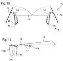
- Fig. 18 shows the roof unit 84 in a fully open position.
- the roof wings 16 are located to the side of the side walls 86, i.e. outside the imaginary side plane of the container housing 4 spanned by the side walls 86. This provides a lot of space for lowering objects into the interior of the container housing 4 from above, for example for introducing the canisters 20 on the base 30.
- a seal 106 is arranged in the upper region of the side wall 86, against which the corresponding roof wing 16 rests in the closed wing 16 with a lateral overhang 108 with which the roof wing 16 encompasses the upper side edge 102 of the container side wall 86 from above and from the side .
- This overhang 108 presses from the side against the seal 106 from the outside.
- the closed position of the roof wing 16 is in FIG Fig. 19 indicated in dotted lines. It is also possible that the roof wing 16 rests on the seal 106 from above when this, as in FIG Fig. 19 is shown, the upper side edge of the container side wall 86 engages around the top.
- the outer edges of the roof wing 16 move towards the lateral container wall 26 and the seal 106 at a sliding angle of less than 10 ° to the horizontal.
- the opening movement of the roof unit 84 also has the advantage that water, sand or dirt lying on the container roof 14 slides laterally outward when it is opened and is moved a little away from the side wall 86 by the sideways movement of the outer edge of the roof wing 16. Dirt or water thus flows off the side of the roof wing 16 and falls down from the container side wall 86 at a distance. Penetration of dirt, sand or water into the interior of the container is thus avoided.
- each roof wing 16 has an inner cover 110.
- the inner cover 110 overlaps the upper side edge 102 of the container housing 4 or the upper edge of the side wall 86, so that it is protected from rain or falling dirt in the course of the inner cover 110.
- the inner cover 110 covers about 75% of the seal 106 and is designed as an elongated plate that is in the Figures 4 , 5 , 8th , 9 , 10th you can see.
- each roof wing 16 comprises two links 92 and two motor units 96, so that each roof wing 16 can be lifted symmetrically in terms of forces and pivoted outward.
- the rear link 92 can be set a little forward in relation to the position shown in the figures.
- the links 92 are supported in the open state on the side wall 86 of the container housing 4, as from Fig. 18 you can see.
- the motor units 96 can be switched to free and the roof wings 16, pushed to the side by their weight, remain securely in their open position. In the closed position, the roof wings 16 rest on the container side walls 86 and front and rear supports (not shown), so that the motor units 96 can also be switched free of force in this position and the roof unit 84 remains securely closed.
- an operator controls the control means 62 via corresponding commands for opening the container roof 14 via the input means 12.
- the control unit 62 controls the motor units 96 of the roof unit 84 so that they bring the roof wings 16 from their closed position or closed position into their open position, as in FIG Fig. 18 is shown.
- the missile container 2 is removed from the in Fig. 1 closed state shown in Fig. 8 Brought open state shown.
- the movement means 26 is then transferred from the in FIG Fig. 8 in the storage position shown in Fig. 4 shown operating position brought.
- the movement means 26 specifically the movable members 32 in the exemplary embodiment shown, presses against the roof flaps 18, which are shown in FIG Fig.
- the roof flaps 18 are pressed downward into an open position against a spring force pressing in the closed position.
- the roof flaps 18 are closure means which release a corresponding passage for the movement means 26 and close it again.
- the movement means 26 moves completely into its operating position and leans against the rear wall of the container housing 4.
- the antenna 22 On the basis of corresponding commands in the input means 12, the antenna 22 is folded up. It also presses against a roof flap 18, which in Fig. 1 is shown so that it is pressed downwards. Alternatively, the antenna 22 can also be unfolded before the movement means 26 is moved into its operating position.
- the operator controls the closing of the roof unit 84 so that the two roof wings 16 close again and the in Fig. 3 reach shown closed position.
- the container roof 14 is completely closed.
- the openings in the container roof 14 released by the roof flaps 18 now serve to enable the antenna 22 and the moving means 26 to be guided through the closed container roof 14 without the roof unit 84 having to be open for this purpose.
- the missile container 2 can thus also be kept closed in its operating position, in which case it is expediently closed in a splash-proof manner. Rain or flying dust therefore does not get into the interior of the container.
- the roof unit 84 can be opened again and the antenna 22 and the moving means 26 can be returned to the storage position.
- the corresponding elements move out of the bushings and the roof flaps 18 move back into their closed position with a spring drive. This closes the leadthroughs so that when the roof wing 16 is closed, the container roof 14 is closed again.
- positive locking means 112 see FIG Fig. 19
- the roof wings 16 are secured in their closed position in that a securing means 116 fixed to the housing (see Fig. 18 ), which can be designed as a retaining bolt, for example, moves into the upper roof wing from the front and thus blocks an opening movement of the roof wing.
- the upper wing 16, in Fig. 18 if it is the left roof wing, it engages in the closed position in the inner area over the lower roof wing 16, which in Fig. 18 the right roof wing 16 is. This overlapping also prevents the lower roof wing 16 from moving out of the closed position without opening the upper roof wing 16.
- the Figures 20 and 21 show the antenna 22 in a storage state of the missile container 2 ( Fig. 1 and Fig. 20 ) and an operating state of the missile container 2 ( Fig. 3 and Fig. 21 .)
- a movement motor 118 in the form of a hydraulic cylinder
- the antenna 22 is unfolded from the position completely inside the container volume to a vertical position in which the antenna 22 protrudes through the roof opening 24.
- the movement motor generates a rotation of the antenna 22 around an axis of rotation from a linear movement.
- the antenna 22 is also folded in by the movement motor 118.
Description
Die Erfindung betrifft einen Flugkörperbehälter mit einem Behältergehäuse, zumindest einem darin in Lagerposition angeordneten Kanister zum Tragen eines Flugkörpers und einem Bewegungsmittel zum Bewegen des Kanisters von einer Lagerposition in eine Betriebsposition. Ein Flugkörper der eingangs genannten Art mit entsprechenden Behälter und Träger ist aus
Flugkörper werden in der Regel über längere Zeiträume gelagert und sind zu diesem Zweck im Behältergehäuse des Flugkörperbehälters gelagert. Auch bei einem Transport sind sie innerhalb des Behältergehäuses des Flugkörperbehälters angeordnet und darin fest verschlossen gehalten. Um in Gefechtsbereitschaft versetzt werden zu können, müssen die Flugkörper mit ihrem Kanister aus dem Behältergehäuse herausgenommen und entsprechend so positioniert werden, dass sie starten können, ohne durch ihren Abgasstrahl Schäden zu verursachen.Missiles are usually stored for long periods of time and are stored in the container housing of the missile container for this purpose. Even during transport, they are arranged within the container housing of the missile container and held tightly closed therein. In order to be able to be put into combat readiness, the missiles and their canisters must be removed from the container housing and positioned accordingly so that they can take off without causing damage from their exhaust gas jet.
Zum Schutz der Flugkörper während der Lagerung und des Transports sollte das Behältergehäuse in der Weise verschließbar sein, dass der Inhalt zumindest spritzwassergeschützt ist, sodass der Flugkörperbehälter durch Regen, Wind und Schnee transportiert werden kann, ohne dass innere Elemente darunter leiden. Es ist jedoch auch möglich, dass der Flugkörperbehälter lange in Gefechtsbereitschaft bzw. Alarmbereitschaft gehalten bleiben muss. Auch hier kann es sein, dass der Flugkörperbehälter den Witterungen ausgesetzt ist, seien es Regen, Schnee oder Wind oder auch Staub oder Wüstenflugsand. Um Beschädigungen der Elemente im Inneren des Flugkörperbehälters zu vermeiden, ist es daher vorteilhaft, wenn das Behältergehäuse auch in der Betriebsposition des Kanisters verschließbar ist. Zumindest sollten Teile des Innenraums des Behältergehäuses durch ein Behälterdach geschützt werden.To protect the missile during storage and transport, the container housing should be closable in such a way that the contents are at least splash-proof so that the missile container can be transported through rain, wind and snow without internal elements suffering. However, it is also possible that the missile container must remain in combat readiness or on alert for a long time. Here, too, the missile container may be exposed to the elements, be it rain, snow or wind, or even dust or desert sand. In order to avoid damage to the elements in the interior of the missile container, it is therefore advantageous if the container housing can also be closed in the operating position of the canister. At least parts of the interior of the container housing should be protected by a container roof.
Es ist daher eine Aufgabe der vorliegenden Erfindung, einen Flugkörperbehälter anzugeben, bei dem im Inneren des Behältergehäuses angeordnete Elemente zumindest teilweise vor äußeren Witterungseinflüssen geschützt werden können. Die Aufgabe wird durch einen Flugkörperbehälter nach dem Anspruch 1 gelöst. Diese Aufgabe wird durch einen Flugkörperbehälter der eingangs genannten Art gelöst, bei dem erfindungsgemäß in Betriebsposition der Kanister vom Bewegungsmittel zumindest teilweise außerhalb des Behältergehäuses gehalten ist und das Behälterdach einen Behälterinnenraum nach außen abschirmend geschlossen ist. Im Behälterinnenraum angeordnete Geräte können vor äußeren Witterungseinflüssen geschützt werden und der Flugkörperbehälter kann über einen längeren Zeitraum in Alarm- oder Gefechtsbereitschaft gehalten werden.It is therefore an object of the present invention to provide a missile container in which elements arranged in the interior of the container housing can be at least partially protected from external weather influences. The object is achieved by a missile container according to claim 1. This object is achieved by a missile container of the type mentioned, in which, according to the invention, in the operating position, the canister is at least partially held by the moving means outside the container housing and the container roof is closed to shield a container interior from the outside. Devices arranged in the interior of the container can be protected from external weather conditions and the missile container can be kept in alert or combat readiness for a longer period of time.
Die Betriebsposition des Kanisters kann eine Gefechtsposition sein, von der aus ein im Flugkörper gehaltener Flugkörper regulär gestartet wird. Die Betriebsposition kann jedoch eine Wartungs- oder Reparaturposition sein, in der der Kanister zum Warten oder Reparieren des Flugkörpers oder des Kanisters gehalten ist.The operating position of the canister can be a combat position from which a missile held in the missile is regularly launched. However, the operating position can be a maintenance or repair position in which the canister is held for servicing or repairing the missile or the canister.
Das Bewegungsmittel ist innerhalb des Behältergehäuses strukturfest verankert, sodass es zum Halten des Kanisters außerhalb des Behältergehäuses durch das Behältergehäuse hindurchgeführt werden muss. Dieses Hindurchführen kann zwar abweichend von der Erfindung durch eine oder mehrere der Behälterseitenwände erfolgen, erfindungsgemäß erfolgt ein Hindurchführen durch das Behälterdach . In dem Behältergehäuse ist somit also zweckmäßigerweise eine Aussparung vorhanden, durch die das Bewegungsmittel in Betriebsposition hindurchgeführt ist. Ist das Bewegungsmittel in Lagerposition außerhalb dieser Aussparung angeordnet, so wird die Aussparung zweckmäßigerweise verschlossen, um das Behältergehäuse auch in Lagerposition dicht zu halten.The moving means is anchored in a structurally fixed manner inside the container housing, so that it has to be passed through the container housing in order to hold the canister outside the container housing. In a departure from the invention, this passage can take place through one or more of the container side walls, according to the invention it is passed through the container roof. In the container housing there is therefore expediently a recess through which the movement means is passed in the operating position. If the movement means is arranged outside this recess in the storage position, the recess is expediently closed in order to keep the container housing tight in the storage position.
Der Flugkörper ist zweckmäßigerweise ein Raketenflugkörper, also ein Flugkörper mit einem Raketentriebwerk, insbesondere ein Boden-Luft-Flugkörper, ein Boden-Boden-Flugkörper oder ein seegestützter Flugkörper. Der Flugkörper ist ein unbemannter Flugkörper und zweckmäßigerweise mit einem Gefechtskopf ausgestattet, der eine Detonationsladung beherbergen kann. Die Erfindung ist nicht auf Flugkörper und einen Behälter für einen Flugkörper beschränkt. Anstelle eines Flugkörpers kann ein anderer Gegenstand bewegt werden.The missile is expediently a rocket missile, that is to say a missile with a rocket engine, in particular a surface-to-air missile, a surface-to-surface missile or a sea-based missile. The missile is an unmanned missile and expediently equipped with a warhead that can accommodate a detonation charge. The invention is not limited to missiles and a container for a missile. Instead of a missile, another object can be moved.
Der Kanister dient zum Tragen des Flugkörpers und außerdem zweckmäßigerweise zu dessen Lagerung im verschlossenen Flugkörperbehälter und vorteilhafterweise auch zum Halten bei einem Abschuss. Der Flugkörper wird somit zweckmäßigerweise aus dem Kanister abgeschossen und dieser ist insofern für einen solchen Abschuss vorbereitet. Die Lagerposition ist eine solche Position des Kanisters, in der der Flugkörper beziehungsweise der Kanister über einen Lagerzeitraum gelagert ist, beispielsweise über mehrere Monate, insbesondere über mehrere Jahre.The canister serves to carry the missile and also expediently to store it in the closed missile container and advantageously also to hold it when it is launched. The missile is thus expediently launched from the canister and the canister is prepared for such a launch. The storage position is a position of the canister in which the missile or the canister is stored over a storage period, for example over several months, in particular over several years.
Die Lagerposition ist eine Position, in der der Flugkörper bzw. der Kanister mit dem Flugkörper über einen längeren Zeitraum gelagert wird. Sie kann auch eine Transportposition sein, in der der Kanister und der Flugkörper auf oder in einem Fahrzeug transportiert werden. Die Betriebsposition ist eine Position, in der der Kanister in Betrieb ist. Ein solcher Betrieb kann ein Abschuss des Flugkörpers aus dem Kanister sein, ein Wartungsbetrieb, in dem der Kanister gewartet oder repariert wird, ein Testbetrieb, beispielsweise zum Testen von Sensoren des Kanisters beziehungsweise des Flugkörpers, oder ein anderer geeigneter Betrieb des Kanisters. Die Betriebsposition ist eine andere Position als die Lagerposition, wobei der Kanister zweckmäßigerweise in der Betriebsposition relativ zur Lagerposition verschwenkt ist.The storage position is a position in which the missile or the canister with the missile is stored for a longer period of time. It can also be a transport position in which the canister and the missile are transported on or in a vehicle. The operating position is a position in which the canister is operating. Such an operation can be a launching of the missile from the canister, a maintenance operation in which the canister is serviced or repaired, a test operation, for example for testing sensors of the canister or the missile, or another suitable operation of the canister. The operating position is a different position than the storage position, the canister expediently being pivoted relative to the storage position in the operating position.
Das Behältergehäuse ist zweckmäßigerweise ein rund um den Flugkörper geschlossenes Gehäuse. Es weist zweckmäßigerweise die Abmessungen eines 20-Fuß-ISO-Transportcontainers auf. Hierdurch ist der Flugkörperbehälter mit typischen logistischen Systemen für Container kombinierbar und nutzbar. Weiter ist es vorteilhaft, wenn das Behältergehäuse spritzwasserfest verschließbar ist, sodass der Innenraum des Behältergehäuses vor stark beeinträchtigenden Witterungseinflüssen, wie Regen oder Sturm, geschützt ist. Bei Ausgestaltung des Behältergehäuses äußerlich analog zu einem Standard-Transportcontainer kann ein solcher Witterungsschutz erreicht werden. Zudem ist ein einfacher und unauffälliger Transport möglich. Zweckmäßigerweise ist das Behältergehäuse mit massiven Seitenwänden und einer Zugangstür ausgestattet. Zusätzlich ist ein Bedienfeldbereich mit einer Schutzabdeckung vorteilhaft, beispielsweise einer Schutzklappe, sowie insbesondere ein Anschluss für Versorgungsleitungen vorhanden.The container housing is expediently a housing that is closed around the missile. It expediently has the dimensions of a 20-foot ISO transport container. As a result, the missile container can be combined and used with typical logistic systems for containers. It is also advantageous if the container housing can be closed in a splash-proof manner, so that the interior of the container housing is protected from bad weather influences, such as rain or storms. Such weather protection can be achieved if the container housing is designed externally in the same way as a standard transport container. In addition, easy and inconspicuous transport is possible. The container housing is expediently equipped with solid side walls and an access door. In addition, a control panel area with a protective cover, for example a protective flap, and in particular a connection for supply lines is advantageous.
Während der Lagerung und des Transports ist der Flugkörperbehälter beziehungsweise dessen Behältergehäuse zweckmäßigerweise geschlossen, wie oben beschrieben. Es kann jedoch auch sein, dass sich der Flugkörperbehälter über einen längeren Zeitraum in Alarmbereitschaft oder Aktivierungsbereitschaft befindet, in der der Kanister in Gefechtsposition angeordnet ist. Um das Innere des Behältergehäuses auch in diesem Zustand über einen längeren Zeitraum vor äußeren Einflüssen zu schützen, ist es vorteilhaft, wenn das Behältergehäuse auch in Gefechtsbereitschaft des Flugkörperbehälters beziehungsweise in Gefechtsposition des Kanisters geschlossen ist. Wie im Lager- oder Transportzustand ist auch hierbei eine Spritzwasserfestigkeit, insbesondere von allen Seiten, vorteilhaft.During storage and transport, the missile container or its container housing is expediently closed, as described above. However, it can also be the case that the missile container is in a state of alert or readiness for activation over a longer period of time in which the canister is arranged in the combat position. In order to protect the interior of the container housing from external influences over a longer period of time in this state as well, it is advantageous if the container housing is also closed when the missile container is ready for action or when the canister is in combat position. As in the storage or transport state, splash resistance, in particular from all sides, is advantageous here too.
Am Bewegungsmittel sind zweckmäßigerweise mehrere Kanister zum Tragen jeweils mindestens eines Flugkörpers angeordnet. Üblich sind vier oder acht Kanister pro Kanistereinheit, die als Einheit, z.B. fest in sich zusammengefügt, am Bewegungsmittel befestigt sind.A plurality of canisters each for carrying at least one missile are expediently arranged on the moving means. Four or eight canisters per canister unit, which are used as a unit, e.g. firmly joined together, attached to the means of movement.
Das Bewegungsmittel dient zum Bewegen des Kanisters von der Lagerposition in die Betriebsposition und kann hierzu ein Koppelgetriebe umfassen. Das Bewegungsmittel ist zweckmäßigerweise dazu vorbereitet, eine Bewegung auszuführen, die mehr Freiheitsgrade aufweist als eine einfache Rotation um eine einfache Rotationsachse. Hierbei ist ein höherer Freiheitsgrad nicht zwingend als eine höhere Dimensionalität der Bewegung zu verstehen, da eine eindimensionale Bewegung ausreicht. Es soll vielmehr eine komplexere Bewegungsbahn als eine Gerade oder einfache Kreis- oder Ellipsenbahn ermöglicht werden, beispielsweise eine Kombination aus zwei Kreisbahnen mit verschiedenen Mittelpunkten.The moving means is used to move the canister from the storage position into the operating position and can for this purpose comprise a coupling gear. The movement means is expediently prepared to carry out a movement which has more degrees of freedom than a simple rotation about a simple rotation axis. Here, a higher degree of freedom is not necessarily to be understood as a higher dimensionality of the movement, since a one-dimensional movement is sufficient. Rather, a more complex movement path than a straight line or a simple circular or elliptical path should be made possible, for example a combination of two circular paths with different centers.
Vorteilhafterweise umfasst das Behältergehäuse eine Dacheinheit, durch die eine Dachöffnung des Behältergehäuses geöffnet und wieder verschlossen werden kann. Hierzu ist die Dacheinheit vom übrigen Behältergehäuse beweglich gelagert, sodass sie die Dachöffnung durch eine Schwenkbewegung, eine translatorische Bewegung oder eine Kombinationsbewegung verschließen kann. Die Dacheinheit kann mehrere Dachelemente umfassen, beispielsweise zwei symmetrisch zueinander bewegliche Dachflügel oder andere Elemente. Einem guten Abdichten des Behältergehäuses ist es dienlich, wenn die Dacheinheit zwei Dachflügel aufweist, die in geschlossener Position einander teilweise überdecken. Zwischen den beiden Dachflügeln kann eine Dichtung angeordnet sein, die den Behälterinnenraum nach außen abdichtet.The container housing advantageously comprises a roof unit through which a roof opening of the container housing can be opened and closed again. For this purpose, the roof unit is movably supported by the rest of the container housing, so that it can close the roof opening by a pivoting movement, a translational movement or a combination movement. The roof unit can comprise several roof elements, for example two roof wings or other elements that can be moved symmetrically to one another. It is useful for a good sealing of the container housing if the roof unit has two roof wings which partially cover one another in the closed position. A seal that seals the container interior from the outside can be arranged between the two roof wings.
Die Dacheinheit und das Bewegungsmittel sind zweckmäßigerweise so aufeinander abgestimmt, dass die Dacheinheit sowohl bei einer Lage des Bewegungsmittels in der Lagerposition als auch bei einer Lage des Bewegungsmittels in Betriebsposition schließbar ist. Im geschlossenen Zustand der Dacheinheit ist der Behälterinnenraum nach außen abgeschirmt, wobei zweckmäßigerweise der gesamte Behälterinnenraum des Behältergehäuses nach außen abgeschirmt und verschlossen ist. Unabhängig von der Dacheinheit können weitere Öffnungen im Behältergehäuse vorhanden sein, beispielsweise eine Tür zum Begehen des Behälterinnenraums, ein Fenster, eine weitere Dachklappe oder mehrere dieser Elemente oder andere Elemente. Hierbei kann die Abschirmung des Behälterinnenraums nach außen so verstanden werden, dass all diese Elemente geschlossen sind.The roof unit and the movement means are expediently coordinated with one another in such a way that the roof unit can be closed both when the movement means is in the storage position and when the movement means is in the operating position. In the closed state of the roof unit, the interior of the container is shielded from the outside, the entire interior of the container housing expediently being shielded from the outside and closed. Regardless of the roof unit, there can be further openings in the container housing, for example a door for entering the container interior, a window, another roof flap or several of these elements or other elements. Here, the shielding of the interior of the container from the outside can be understood to mean that all of these elements are closed.
Erfindungsgemäß weist das Behälterdach eine Durchführung auf, durch die das Bewegungsmittel in Betriebsposition hinausragt. Die Durchführung kann eine Ausnehmung sein, die durch eine Dachklappe oder ein anderes Verschlusselement verschließbar ist. Die Dachklappe bzw. das andere Element ist zweckmäßigerweise von der Dacheinheit, wie einem Dachflügel, verschieden und zu diesem zusätzlich vorhanden. Ist das Bewegungsmittel nicht durch die Durchführung hindurchgeführt, sondern woanders positioniert, sollte die Durchführung verschlossen sein oder zumindest verschließbar sein, um den Flugkörperbehälter auch in Lagerposition des Kanisters ausreichend verschließen zu können. Es ist also zweckmäßig, wenn die Durchführung bei aus der Durchführung herausbewegtem Bewegungsmittel verschlossen ist, beispielsweise durch eine Dachklappe. Der Begriff der Dachklappe, wie auch der Begriff des Dachflügels, impliziert eine rotatorische Öffnungs- oder Schließbewegung. Diese Begriffe sollen jedoch nicht auf eine solche Schließbewegung reduziert sein, sodass auch ein rein translatorisch oder in einer Kombinationsbewegung öffnendes oder schließendes Element als Dachklappe bzw. Dachflügel bezeichnet wird.According to the invention, the container roof has a passage through which the movement means protrudes in the operating position. The passage can be a recess that can be closed by a roof flap or another closure element. The roof flap or the other element is expediently different from the roof unit, such as a roof wing, and is present in addition to it. If the moving means is not passed through the leadthrough but is positioned elsewhere, the leadthrough should be closed or at least be able to be closed so that the missile container can also be adequately closed in the storage position of the canister. It is therefore useful if the bushing is closed when the moving means is moved out of the bushing, for example by a roof flap. The term roof flap, like the term roof wing, implies a rotary opening or closing movement. However, these terms should not be reduced to such a closing movement, so that an element that opens or closes purely translationally or in a combination movement is also referred to as a roof flap or roof wing.
Vorteilhafterweise ist die Durchführung unmittelbar neben einem Bereich der Dachöffnung angeordnet, der durch einen Dachflügel verschlossen werden kann. Dieser Dachöffnungsbereich und die Durchführung grenzen somit unmittelbar aneinander an, so dass die Durchführung und die Dachöffnung eine zusammenhängende Öffnung bilden. Hierdurch kann das Bewegungsmittel aus der Dachöffnung in die Durchführung einfahren und somit aus diesem Bereich der Dachöffnung, der vom Dachflügel verschlossen wird, ausfahren.The bushing is advantageously arranged directly next to an area of the roof opening that can be closed by a roof wing. This roof opening area and the implementation are thus directly adjacent to one another, so that the implementation and the roof opening form a coherent opening. As a result, the moving means can move out of the roof opening into the bushing and thus move out of this area of the roof opening, which is closed by the roof wing.
Vorteilhafterweise ist die Dachklappe in der Weise ausgeführt, dass sie bei einem Herausbewegen des Bewegungsmittels aus der Durchführung selbsttätig schließt. Dieses Schließen kann motorgetrieben, federgetrieben oder auf eine andere Weise erfolgen. Ein federgetriebenes Schließen ist hierbei besonders einfach, kostengünstig und zuverlässig erreichbar.The roof flap is advantageously designed in such a way that it closes automatically when the movement means is moved out of the passage. This closing can be motor-driven, spring-driven or in some other way. A spring-driven closing is particularly easy, inexpensive and reliable to achieve.
Ebenfalls einfach kann die Dachklappe gehalten sein, wenn sie und das Bewegungsmittel derart zueinander angeordnet und ausgeführt sind, dass das Bewegungsmittel die Dachklappe durch ein Bewegen in die Betriebsposition aufdrückt. So kann das Bewegungsmittel die Dachklappe beispielsweise gegen eine Federkraft aufdrücken, die bei einem Herausbewegen des Bewegungsmittels aus der Durchführung die Dachklappe wieder in ihre Verschlussposition drückt. Vorteilhafterweise füllt das Bewegungsmittel die Durchführung vollständig aus, sodass der Behälterinnenraum bei einem verschlossenen Dachelement und in der Position des Bewegungsmittels in der Betriebsposition verschlossen ist, also auch die Durchführung verschlossen ist.The roof flap can also be held in a simple manner if it and the movement means are arranged and designed in relation to one another in such a way that the movement means presses the roof flap open by moving it into the operating position. For example, the movement means can press the roof flap open against a spring force which, when the movement means is moved out of the passage, presses the roof flap back into its closed position. Advantageously, the movement means completely fills the passage, so that the interior of the container is closed with a closed roof element and in the position of the movement means in the operating position, ie the passage is also closed.
Eine weitere Ausführungsform der Erfindung schlägt vor, dass die Dacheinheit zumindest ein Dachelement, beispielsweise in Form eines Dachflügels, aufweist, der auf dem Behältergehäuse aufliegt. Ein Öffnen der Dachöffnung kann durch ein Bewegen des Dachelements, im Folgenden vereinfacht als Dachflügel bezeichnet, nach oben auf einfache Weise geschehen. Zweckmäßigerweise ist der Dachflügel vollständig nach oben vom Behältergehäuse abhebbar. Hierunter kann verstanden werden, dass der Dachflügel an allen seinen Seitenkanten, beispielsweise seinen vier Seitenkanten, vom Behältergehäuse abhebbar ist. Die Abhebbarkeit nach oben ist zweckmäßigerweise so ausgeführt, dass auf eine Lagerung des Dachflügels im Behältergehäuse verzichtet werden kann. Hierdurch kann eine Abdichtung des Behältergehäuses erleichtert werden, da eine Lagerung des Dachflügels im Behältergehäuse gegebenenfalls nicht leicht abdichtbar ist. Das Abheben geschieht zweckmäßigerweise motorgetrieben. Hierzu umfasst der Flugkörperbehälter zweckmäßigerweise ein Öffnungsmittel zum Öffnen des Dachflügels, insbesondere durch ein vollständiges Anheben des Dachflügels vom Behälterdach. Es kann ein einziger Dachflügel ausreichen, um die Dachöffnung zu verschließen, wobei ebenso gut zwei oder mehr Dachflügel für diese Aufgabe vorhanden sein können.Another embodiment of the invention proposes that the roof unit has at least one roof element, for example in the form of a roof wing, which rests on the container housing. The roof opening can be opened in a simple manner by moving the roof element, referred to in the following simply as the roof wing, upwards. The roof wing can expediently be lifted completely upwards from the container housing. This can be understood to mean that the roof wing can be lifted off the container housing on all of its side edges, for example its four side edges. The ability to be lifted upwards is expediently designed in such a way that there is no need to mount the roof wing in the container housing. Sealing of the container housing can hereby be facilitated, since a mounting of the roof wing in the container housing may not be easily sealable. The lift-off is expediently motor-driven. For this purpose, the missile container expediently comprises an opening means for opening the roof wing, in particular by lifting the roof wing completely from the container roof. A single roof wing can be sufficient to close the roof opening, and two or more roof wings can just as easily be present for this task.
Einer guten Abdichtung des Behältergehäuses nach außen ist es dienlich, wenn der Dachflügel die Seitenoberkante der Behälterseitenwand von oben und seitlich umgreift. Die Behälterseitenwand ist ein Teil des Behältergehäuses und ragt zweckmäßigerweise senkrecht nach oben auf. Durch das Umgreifen der Seitenoberkante von oben und seitlich kann auf eine von oben zugängliche Abdichtung des Behälterdachs verzichtet werden, so dass Wasser, ohne eine solche Dichtungsstelle zu berühren, seitlich vom Behälterdach abfließen kann.A good seal of the container housing to the outside is useful if the roof wing engages around the upper side edge of the container side wall from above and from the side. The container side wall is part of the container housing and expediently protrudes vertically upwards. By reaching around the upper side edge from above and from the side, a seal of the container roof that is accessible from above can be dispensed with, so that water can flow off the side of the container roof without touching such a sealing point.
Beim Lagern, beim Transport oder auch in Alarmbereitschaft kann es vorkommen, dass sich Wasser, Flugsand, Blätter oder dergleichen auf dem Behälterdach sammeln. Ist das Öffnen des Dachflügels mit einem Verkippen verbunden, so fließt das Wasser, beziehungsweise rutscht die Verschmutzung, seitlich vom Dachflügel ab. Hierbei ist es sinnvoll, wenn das Wasser, beziehungsweise der Schmutz, dort herab fällt, wo es auch bei Wind nicht in den Behälterinnenraum geblasen werden kann, also zweckmäßigerweise ein Stück weit weg von der Behälteraußenwand. Hierzu wird vorgeschlagen, dass der Flugkörperbehälter ein Öffnungsmittel zum Öffnen des Dachflügels durch ein Schwenken des Dachflügels nach oben und zur Seite aufweist. Beim Öffnen kippt der Flügel zweckmäßigerweise nach außen, so dass beispielsweise Sand auf den Flügel nach außen rutscht, ohne die Behälteraußenseite berühren zu können.During storage, transport or even when on alert, water, drifting sand, leaves or the like may collect on the container roof. If opening the roof wing is associated with tilting, the water flows or the dirt slips off the side of the roof wing. It makes sense here if the water, or the dirt, falls down where it cannot be blown into the interior of the container even when there is wind, that is to say expediently a little way away from the outer wall of the container. For this purpose, it is proposed that the missile container has an opening means for opening the roof wing by pivoting the roof wing upwards and to the side. When opening, the wing expediently tilts outwards so that, for example, sand slides outwards on the wing without being able to touch the outside of the container.
Einer einfachen Konstruktion des Öffnungsmittels zum Öffnen des Dachflügels ist es zuträglich, wenn der Dachflügel in einer einzigen Drehachse schwenkbar gelagert ist. Die Drehachse ist zweckmäßigerweise im Behälterinnenraum angeordnet, also vom Behältergehäuse umgriffen. Ebenso ist die bewegliche Lagerung des Dachflügels, also ein Lager, ein Scharnier oder dergleichen, innerhalb des Behälterinnenraums positioniert.A simple construction of the opening means for opening the roof wing is beneficial if the roof wing is mounted pivotably in a single axis of rotation. The axis of rotation is expediently arranged in the interior of the container, that is to say encompassed by the container housing. The movable mounting of the roof wing, that is to say a bearing, a hinge or the like, is also positioned within the container interior.
Eine seitliche Bewegung des Dachflügels beim Öffnen kann einfach erreicht werden, wenn die Drehachse um mehr als 5% der Behälterbreite unter der Behälteroberkante, auf dem der Dachflügel aufliegt, angeordnet ist. Insbesondere ist die Drehachse um mehr als 10%, zweckmäßigerweise sogar um mehr als 25% der Behälterbreite unter der Behälteroberkante angeordnet.A lateral movement of the roof wing when opening can easily be achieved if the axis of rotation is arranged by more than 5% of the container width below the upper edge of the container on which the roof wing rests. In particular, the axis of rotation is arranged by more than 10%, expediently even by more than 25% of the container width below the upper edge of the container.
Um ein seitliches Abtauchen des Dachflügels bereits zu Beginn der Öffnungsbewegung zu vermeiden oder zumindest gering zu halten, ist es vorteilhaft, wenn die Drehachse um weniger als 20%, insbesondere weniger als 10% der Behälterbreite entfernt von der seitlichen Behälterwand angeordnet ist, um die der Dachflügel schwenkt.In order to prevent or at least keep the roof wing from dipping sideways at the beginning of the opening movement, it is advantageous if the axis of rotation is less than 20%, in particular less than 10% of the container width away from the lateral one Container wall is arranged around which the roof wing pivots.
Eine seitliche Dichtungsfläche des Behältergehäuses und/oder des Dachflügels kann besonders einfach und zuverlässig abgedichtet werden, wenn der Dachflügel beim Schließen eher horizontal an die Seitenoberkante der Behälterseitenwand anfährt. Hierzu ist vorteilhaft, wenn der Flugkörperbehälter ein Öffnungsmittel zum Bewegen des Dachflügels durch ein Schwenken des Dachflügels in der Weise aufweist, dass die Außenseite des Dachflügels beim Schließen mit einem Anschiebewinkel von weniger als 20°, insbesondere weniger als 10°, zur Horizontalen an die Behälterwand bewegt ist. Vorteilhafterweise hebt hierbei der Dachflügel an seiner Innenseite mehr nach oben als zur Seite ab.A lateral sealing surface of the container housing and / or the roof wing can be sealed particularly easily and reliably if the roof wing approaches the upper side edge of the container side wall rather horizontally when it is closed. For this purpose, it is advantageous if the missile container has an opening means for moving the roof wing by pivoting the roof wing in such a way that the outside of the roof wing when closing with a push angle of less than 20 °, in particular less than 10 °, to the horizontal on the container wall is moved. Advantageously, the roof wing lifts up on its inside more upwards than to the side.
Zum Schutz einer Abdichtung ist es weiter vorteilhaft, wenn der Dachflügel eine Innenabdeckung aufweist, die im geöffneten Zustand des Dachflügels die Seitenoberkante des Behältergehäuses abdeckt, so dass diese geschützt ist. Hierdurch kann auch eine Dichtung auf der Seitenoberkante oder an der Seitenoberkante geschützt werden. Die Abdeckung erfolgt zumindest über 50% der Gesamtlänge der Seitenoberkante.To protect a seal, it is also advantageous if the roof wing has an inner cover which, when the roof wing is open, covers the upper side edge of the container housing so that it is protected. This can also protect a seal on the top edge of the side or on the top edge of the side. At least 50% of the total length of the top edge is covered.
Um den Flugkörperbehälter sicher betreten zu können, ist es vorteilhaft, wenn das Öffnungsmittel sowohl im geöffneten als auch im geschlossenen Zustand des Dachflügels kräftefrei ist. Dies kann einfach erreicht werden, wenn sich der Dachflügel im geöffneten Zustand an einem Abstützmittel abstützt, so dass das Öffnungsmittel kräftefrei ist und der Dachflügel in einer sicheren Öffnungsposition verharrt. Das Abstützen kann direkt oder mittelbar zum Beispiel über ein oder mehrere Elemente des Öffnungsmittels geschehen. Das Abstützmittel kann ein Element des Behältergehäuses sein, beispielsweise eine Behälterseitenwand.In order to be able to safely enter the missile container, it is advantageous if the opening means is force-free both in the open and in the closed state of the roof wing. This can easily be achieved if the roof wing is supported on a support means in the open state, so that the opening means is free of forces and the roof wing remains in a secure opening position. The support can take place directly or indirectly, for example via one or more elements of the opening means. The support means can be an element of the container housing, for example a container side wall.
Die Erfindung ist in ihrer allgemeinen Form gerichtet auf einen Flugkörperbehälter mit einem Behältergehäuse, einem darin gelagerten Flugkörper und einem Behälterdach.The invention in its general form is directed to a missile canister having a canister housing, a missile stored therein, and a canister roof.
Um im Inneren des Behältergehäuses angeordnete Elemente zumindest teilweise vor äußeren Witterungseinflüssen zu schützten, wird vorgeschlagen, dass erfindungsgemäß der Flugkörper in seiner Startposition zumindest teilweise außerhalb des Behältergehäuses gehalten ist und das Behälterdach geschlossen ist und einen Behälterinnenraum nach außen abschirmt. Oben und in der Figurenbeschreibung beschriebene Details der Erfindung sind auch mit dieser allgemeinen Form kombinierbar.In order to at least partially protect elements arranged inside the container housing from external weather conditions, it is proposed according to the invention that the missile is held in its launch position at least partially outside the container housing and the container roof is closed and shields a container interior from the outside. The details of the invention described above and in the description of the figures can also be combined with this general form.
Beschrieben ist ein Verfahren zum Betrieb eines Flugkörperbehälters mit einem Behältergehäuse und zumindest einem darin gelagerten Kanister zum Tragen eines Flugkörpers, bei dem der Kanister durch ein Bewegungsmittel von eine Lagerposition in eine Betriebsposition bewegt wird.A method is described for operating a missile container with a container housing and at least one canister stored therein for carrying a missile, in which the canister is moved from a storage position into an operating position by a movement means.
Um im Inneren des Behältergehäuses angeordnete Elemente zumindest teilweise vor äußeren Witterungseinflüssen zu schützten und dennoch eine Bewegung des Flugkörpers aus dem Behältergehäuse heraus zu ermöglichen, wird vorgeschlagen, dass erfindungsgemäß ein Dachflügel des Behältergehäuses geöffnet und hierdurch eine Dachöffnung freigegeben wird.In order to at least partially protect elements arranged inside the container housing from external weather conditions and still allow the missile to move out of the container housing, it is proposed according to the invention that a roof wing of the container housing is opened and a roof opening is thereby released.
Zweckmäßigerweise wird der Kanister nach dem Freigeben der Dachöffnung aus der Lagerposition in eine Betriebsposition und hierbei durch die Dachöffnung bewegt. Weiter vorteilhafterweise wird der Dachflügel in der Betriebsposition des Kanisters wieder geschlossen, wodurch die Dachöffnung verschlossen wird. Das Behältergehäuse erreicht hierdurch vorteilhafterweise einen zumindest spritzwassergeschützten Zustand, wodurch Elemente im Behälterinnenraum auch in der Betriebsposition gut geschützt sind.Expediently, after the roof opening has been released, the canister is moved from the storage position into an operating position and through the roof opening. Further advantageously, the roof wing is closed again in the operating position of the canister, whereby the roof opening is closed. In this way, the container housing advantageously achieves an at least splash-proof state, as a result of which elements in the container interior are also well protected in the operating position.
In einer vorteilhaften Ausführungsform der Erfindung wird vorgeschlagen, dass das Bewegungsmittel bei einem Bewegen in die Betriebsposition ein Verschlussmittel des Behälterdachs aufdrückt, das hierdurch eine Durchführung im Behälterdach freigibt. Das Verschlussmittel kann ohne motorischen Eigenantrieb geöffnet werden, so dass es einfach herstellbar ist.In an advantageous embodiment of the invention, it is proposed that the movement means, when moving into the operating position, press on a closure means of the container roof, which thereby releases a passage in the container roof. The closure means can be opened without its own motorized drive, so that it is easy to manufacture.
Mit gleichem Vorteil schließt das Verschlussmittel bei einer Bewegung des Bewegungsmittels aus der Betriebsposition federgetrieben und schließt die Durchführung.With the same advantage, the closure means closes in a spring-driven manner when the movement means is moved out of the operating position and closes the passage.
Ein guter Schutz des Behälterinnenraums vor einer Verschmutzung kann erreicht werden, wenn der Dachflügel bei einer Bewegung aus seiner Verschlussposition heraus zur Seite schwenkt und sogleich zur Seite verfährt, so dass Wasser auf dem Dachflügel seitlich abfließt und von der Behälterseitenwand beabstandet herab fällt. Wasser, Sand oder Verschmutzung kann zuverlässig vom Behälterdach, beziehungsweise Dachflügel, abgeworfen werden, ohne in den Behälterinnenraum zu gelangen.A good protection of the container interior from contamination can be achieved if the roof wing pivots to the side when it moves out of its closed position and immediately moves to the side so that water on the roof wing flows off to the side and falls down at a distance from the container side wall. Water, sand or dirt can be reliably thrown off the tank roof or roof wing without getting into the tank interior.
Beschrieben ist außerdem ein Verfahren zum Betrieb eines Flugkörperbehälters mit einem Behältergehäuse und zumindest einem darin gelagerten Kanister zum Tragen eines Flugkörpers, bei dem ein Dachflügel des Behältergehäuses geöffnet und der Kanister durch ein Bewegungsmittel von einer Lagerposition in eine Betriebsposition zumindest teilweise durch das geöffnete Behälterdach bewegt wird. Zum Schutz von Elementen im Behälterinnenraum wird vorgeschlagen, dass der Dachflügel erfindungsgemäß, während das Bewegungsmittel in der Betriebsposition verbleibt, wieder geschlossen wird und einen Behälterinnenraum zumindest teilsweise nach außen abschirmt.Also described is a method for operating a missile container with a container housing and at least one canister stored therein for carrying a missile, in which a roof wing of the container housing is opened and the canister is moved by a moving means from a storage position to an operating position at least partially through the opened container roof . To protect elements in the container interior, it is proposed that the roof wing according to the invention, while the movement means remains in the operating position, is closed again and at least partially shields a container interior from the outside.
Die bisher gegebene Beschreibung vorteilhafter Ausgestaltungen der Erfindung enthält zahlreiche Merkmale, die in den einzelnen Unteransprüchen teilweise zu mehreren zusammengefasst wiedergegeben sind. Diese Merkmale wird der Fachmann jedoch zweckmäßigerweise auch einzeln betrachten und zu sinnvollen weiteren Kombinationen zusammenfassen.The previously given description of advantageous embodiments of the invention contains numerous features, some of which are summarized in the individual subclaims. The person skilled in the art will, however, also expediently consider these features individually and combine them into meaningful further combinations.
Die oben beschriebenen Eigenschaften, Merkmale und Vorteile, sowie die Art und Weise, wie diese erreicht werden, werden klarer und deutlicher verständlich im Zusammenhang mit der folgenden Beschreibung der Ausführungsbeispiele, die im Zusammenhang mit den Zeichnungen näher erläutert werden. Die Ausführungsbeispiele dienen der Erläuterung der Erfindung und beschränken die Erfindung nicht auf die darin angegebene Kombination von Merkmalen, auch nicht in Bezug auf funktionale Merkmale. Außerdem können dazu geeignete Merkmale eines jeden Ausführungsbeispiels auch explizit isoliert betrachtet, aus einem Ausführungsbeispiel entfernt, in ein anderes Ausführungsbeispiel zu dessen Ergänzung eingebracht und/oder mit einem beliebigen der Ansprüche kombiniert werden.The properties, features and advantages described above, as well as the way in which they are achieved, will become clearer and more clearly understandable in connection with the following description of the exemplary embodiments, which are explained in more detail in connection with the drawings. The exemplary embodiments serve to explain the invention and do not restrict the invention to the combination of features specified therein, not even with regard to functional features. In addition, suitable features of each exemplary embodiment can also be considered explicitly in isolation, removed from one exemplary embodiment, introduced into another exemplary embodiment to supplement it, and / or combined with any of the claims.
Es zeigen:
- Fig. 1
- einen Flugkörperbehälter in einem Lager- oder Transportzustand mit geschlossenem Behältergehäuse,
- Fig. 2
- einen Ausschnitt aus dem Behälterdach des Flugkörperbehälters aus
Fig. 1 , - Fig. 3
- den Flugkörperbehälter in einer Betriebsposition mit ebenfalls geschlossenem Behältergehäuse,
- Fig. 4
- den Flugkörperbehälter mit in Betriebsposition gehaltenen Kanistern und geöffnetem Behälterdach,
- Fig. 5
- den Flugkörperbehälter aus
Fig. 4 in einer teilgeschnittenen Ansicht, - Fig. 6
- eine schematische Seitenansicht des Flugkörperbehälters mit Kanistern in Betriebsposition,
- Fig. 7
- der Flugkörperbehälter aus
Fig. 6 mit Kanistern in Lagerposition, - Fig. 8
- den Flugkörperbehälter aus
Fig. 5 mit Kanistern in Lagerposition, - Fig. 9
- den Flugkörperbehälter aus
Fig. 8 , bei dem die Kanister aus der Lagerposition senkrecht nach oben abgehoben sind, - Fig. 10
- die Kanister bei einem beginnenden Schwenkvorgang,
- Fig. 11
- die Kanister in fortgeschrittenerem Schwenkvorgang,
- Fig. 12
- die Kanister senkrecht ausgerichtet und mit dem rückwändigen Ende nach oben gestellt,
- Fig. 13
- die aus dem Behältergehäuse vollständig herausgehobenen Kanister in einer waagerechten Position,
- Fig. 14
- eine schematisierte Seitendarstellung des Behältergehäuses und des Kanisters in Lagerposition mit Bewegungskurven des Kanisters von seiner Bewegung von der Lagerposition in die Betriebsposition,
- Fig. 15
- der Kanister aus
Fig. 14 in einer um 90° gedrehten Stellung auf den eingezeichneten Bewegungsbahnen, - Fig. 16
- eine schematische Darstellung von zwei Dachflügeln zum Öffnen und Verschließen des Behälterdachs eines Flugkörperbehälters aus den vorangegangenen Figuren,
- Fig. 17
- die beiden Dachflügel in einer leicht geöffneten Position,
- Fig. 18
- die beiden Dachflügel in vollständig geöffneter Position,
- Fig. 19
- eine schematische Detailansicht eines Dachflügels kurz vor und in Schließstellung,
- Fig. 20
- eine Antenne in einer Lagerposition und
- Fig. 21
- die Antennenmechanik aus
Fig. 20 bei einer Betriebsposition der Antenne.
- Fig. 1
- a missile container in a storage or transport state with a closed container housing,
- Fig. 2
- a section from the container roof of the missile container
Fig. 1 , - Fig. 3
- the missile container in an operating position with the container housing also closed,
- Fig. 4
- the missile container with the canisters held in the operating position and the container roof open,
- Fig. 5
- the missile canister
Fig. 4 in a partially cut view, - Fig. 6
- a schematic side view of the missile container with canisters in the operating position,
- Fig. 7
- the missile canister off
Fig. 6 with canisters in storage position, - Fig. 8
- the missile canister
Fig. 5 with canisters in storage position, - Fig. 9
- the missile canister
Fig. 8 , in which the canisters are lifted vertically upwards from the storage position, - Fig. 10
- the canisters when a pivoting process begins,
- Fig. 11
- the canisters in a more advanced pivoting process,
- Fig. 12
- the canisters are aligned vertically and placed with the rear end up,
- Fig. 13
- the canisters completely lifted out of the container housing in a horizontal position,
- Fig. 14
- a schematic side view of the container housing and the canister in the storage position with movement curves of the canister from its movement from the storage position to the operating position,
- Fig. 15
- the canister off
Fig. 14 in a position rotated by 90 ° on the trajectories shown, - Fig. 16
- a schematic representation of two roof wings for opening and closing the container roof of a missile container from the previous figures,
- Fig. 17
- the two roof wings in a slightly open position,
- Fig. 18
- the two roof wings in fully open position,
- Fig. 19
- a schematic detailed view of a roof wing shortly before and in the closed position,
- Fig. 20
- an antenna in a storage position and
- Fig. 21
- the antenna mechanics
Fig. 20 at an operating position of the antenna.
Auf seiner Oberseite hat das Behältergehäuse 4 ein Behälterdach 14 mit zwei zueinander symmetrischen Dachflügeln 16, die sich jeweils über mehr als die Hälfte der Länge des Flugkörperbehälters 2 erstrecken. An dem hinteren Ende des Behälterdachs 14 sind zwei Dachklappen 18 angeordnet, die in
Sowohl bei den in
Der in
Um die Rückwirkungen des Abgasstrahls der startenden Flugkörper auf das Behältergehäuse 4 möglichst gering zu halten, sind die Kanister 20 außerhalb des Behältergehäuses 4 angeordnet und außerdem in angemessener Höhe über dem Grund positioniert. Die Höhe der Unterkante der Kanister 20 beträgt zumindest 80 cm, insbesondere zumindest 1 m. Die Containerrückwand, die in den Figuren nicht gezeigt ist, ist stets verschlossen, sodass Gase des heißen Abgasstrahls nicht in das Innere des Behältergehäuses 4 eindringen.In order to keep the repercussions of the exhaust gas jet of the launching missiles on the
Der Flugkörperbehälter 2 ist universell einsetzbar. Er ist sowohl auf einem festen Boden stehend einsetzbar, als auch auf einem LKW. Auch ein Einsatz auf einem Schiff oder anderen zu schützenden Objekten, beispielsweise einer Öl-Plattform, ist einfach möglich.The
Das Bewegungsmittel 26 umfasst ein kinematisches Koppelgetriebe, das in dieser Ausführungsform zwei spiegelsymmetrische Einheiten an beiden Behälterlängsseiten aufweist. Dabei stellt eine Behälterseitenwand jeweils den ortsfesten Teil des Koppelgetriebes dar. Die Halteeinheit 28 bildet den beweglichen Teil des Koppelgetriebes, der mit den beiden Schwingen bzw. Koppelgliedern der beiden Einheiten des Koppelgetriebes verbunden ist bzw. diese bildet.The movement means 26 comprises a kinematic coupling gear, which in this embodiment has two mirror-symmetrical units on both longitudinal sides of the container. A container side wall represents the stationary part of the linkage. The holding
Die beiden Einheiten des Bewegungsmittels 26 sind jeweils als Koppelgetriebe 46 in Form einer viergliedrigen kinematischen Kette ausgeführt. Das Behältergehäuse 4 dient jeweils als Gehäuseglied bzw. ortsfestes Gehäuseelement. Die Halteeinheit 28 dient beiden Einheiten als Koppel beziehungsweise Koppelglied oder Betriebsglied. Das Koppelgetriebe 46 umfasst ein Hebelgestänge mit vier gehäusefesten Drehpunkten.The two units of the movement means 26 are each designed as coupling gears 46 in the form of a four-link kinematic chain. The
Jedes Koppelgetriebe 46 umfasst zwei bewegliche Glieder 32, 34 in Form von starren Elementen, beispielsweise von Stangen. Jedes der beweglichen Glieder 32, 34 ist an einem gehäusefesten Drehpunkt 36, 38 mit dem Gehäuseglied beziehungsweise dem Behältergehäuse 4 drehbar aber ansonsten ortsfest verbunden. Weiter sind die beweglichen Glieder 32, 34 über bewegliche Drehpunkte 40, 42 mit dem Betriebsglied beziehungsweise der Halteeinheit 28 verbunden. Die Drehpunkte 40, 42 sind hierbei relativ zum Koppelglied beziehungsweise der Halteeinheit 28 starr gelagert.Each
Teile der Koppelgetriebe 46 befinden sich neben der Halteeinheit 28. Diese Ausführungsform lässt schmale Elemente zu, sodass eine sehr breite Halteeinheit 28 verwendet werden kann beziehungsweise die Anordnung aus Bewegungsmittel 26 und Kanistern 20 besonders kompakt ausgeführt werden kann.Parts of the coupling gears 46 are located next to the holding
Das Koppelgetriebe 46 ist in den
In den
Die
Ein erster Teil des Bewegungsablaufs ist durch die
Durch die Rotation der beweglichen Glieder 32 der Koppelgetriebe 46 rotiert auch deren beweglicher Drehpunkt 40 um den gehäusefesten Drehpunkt 36. Die beiden beweglichen Drehpunkte 40 bilden eine Schwenkachse 54, die durch die beiden beweglichen Drehpunkte 40 verläuft und die in
Der Freiheitsgrad der Bewegung der Halteeinheit 28 beziehungsweise der Kanister 20 gegenüber der Behälterstruktur beziehungsweise den ortsfesten Behältergehäuse 4 wird lediglich mit Drehgelenken realisiert. Jedes Koppelgetriebe 46 erzeugt die krummlinige Bewegung somit aus lediglich Schwenkbewegungen um zwei ortsfeste Fixachsen 50, 52.The degree of freedom of movement of the holding
Die Bewegung des Bewegungsmittels 26 wird durch zwei Bewegungsmotoren 48 erzeugt, wobei jedem Koppelgetriebe 46 ein Bewegungsmotor 48 zugeordnet ist. Jeder Bewegungsmotor 48 umfasst zwei Motoreinheiten 58, 60, die beide als Schubgestänge ausgeführt sind. Im gezeigten Ausführungsbeispiel sind beiden Motoreinheiten 58, 60 Hydraulikzylinder, die mit einer Hydraulikpumpe verbunden und durch ein Steuermittel 62 gesteuert sind. Die Hydraulikzylinder wirken direkt auf das Haupttragglied 32 des Koppelgetriebes 46. Die Antriebsleistung wird über vier Hydraulikzylinder, zwei auf jeder Seite, übertragen. Bei einem Hydraulikleck kann damit die Halteeinheit 28 in jeder Position gestoppt werden, um Folgeschäden zu vermeiden.The movement of the movement means 26 is generated by two
Die beiden Motoreinheiten 58, 60 greifen jeweils an einem einzigen Hebel 64 des Koppelgetriebes 46 an, das starr mit einem der beweglichen Glieder 32, 34 verbunden ist, bei dem in den Figuren gezeigten Ausführungsbeispiel dem beweglichen Glied 32. Der Antrieb für die Bewegung des Bewegungsmittels 26 wirkt nur auf ein Getriebeelement, in diesem Fall das bewegliche Glied 32. Beide Motoreinheiten 58, 60 erzeugen die Bewegung des Bewegungsmittels 26 durch eine Längenveränderung, also eine Kontraktion und Expansion. Hierbei können beiden Motoreinheiten 58, 60 die Bewegungskraft ausschließlich durch Expansion erzeugen oder zumindest eine der Motoreinheiten 58, 60 ist zusätzlich zum Aufbringen von Bewegungskraft in das Bewegungsmittel 26 durch Kontraktion vorbereitet. Dies ist vorliegend bei der Motoreinheit 60 der Fall.The two
In vorliegendem Ausführungsbeispiel umfasst jeder Bewegungsmotor 48 ausschließlich längenveränderlich wirksame Motoreinheiten 58, 60, die jeweils um eine Fixachse 66, 68 schwenkbar sind. Diese beiden Fixachsen 66, 68 sind in
Die Lageraufnahmen für die fixen Drehpunkte 36, 38 sowie die für die Drehpunkte der Motoreinheiten 58, 60 liegen in einem relativ kleinen Bereich zusammen, sodass die erforderlichen hoch belasteten Strukturbereiche nicht über große Distanzen zu führen sind. Ein Vierseit zu den vier Fixachsen 50, 52, 66, 68 umfasst hierbei eine maximale Ausdehnung, die kleiner ist, als eine halbe Kanisterlänge.The bearing receptacles for the fixed pivot points 36, 38 as well as those for the pivot points of the
Durch den Antrieb der beiden Bewegungsmotoren 48 bewegen sich die Kanister 20 von der in
Diese translatorische Bewegung ist in den Figuren 14 und 15 durch den Anfang der Bewegungsbahnen 72, 74 dargestellt, die in den
Während das vordere Ende des Kanisters 20 im weiteren Verlauf seiner Bewegung kontinuierlich nach oben gehoben wird, macht die Bewegung des hinteren Teils des Kanisters 20 nach der translatorischen Phase einen scharfen Knick von zumindest 60°, im gezeigten Ausführungsbeispiel sogar von 90°. Die translatorische Phase geht in eine Rotationsphase des Kanisters 20 über. In der Rotations- oder Schwenkphase bewegt sich der in Lagerposition hintere Teil des Kanisters 20 im Wesentlichen horizontal. Der Übergang zwischen vertikaler und horizontaler Bewegung ist kürzer als die translatorische Bewegung, im gezeigten Ausführungsbeispiel nur wenige Zentimeter.While the front end of the
Der Übergang von der translatorischen Bewegungsphase zur rotatorischen Bewegungsphase des Kanisters 20 erfolgt sehr scharf, wie aus den Bewegungsbahnen 72, 74 aus
Die Bewegung des Kanisters 20 senkrecht nach oben wird ermöglicht durch die Position der Fixachse 50 relativ zur Schwenkachse 54 und der Fixachse 52 relativ zur Schwenkachse 56. Die beiden Achspaare aus Fixachse 50 und Schwenkachse 54 beziehungsweise Fixachse 52 und Schwenkachse 56 bilden jeweils eine Ebene, die im Wesentlichen horizontal angeordnet ist. Hierdurch findet der erste Teil der Bewegungsbahnen 72, 74 durch ein Anheben der beiden Schwenkachsen 54, 56 im Wesentlichen senkrecht nach oben statt. Die translatorische Bewegung kann durch die weitgehende Parallelität dieser beiden Ebenen in der Lagerposition erreicht werden. Durch die unterschiedlichen Längen der beiden beweglichen Glieder 32, 34 wird diese Parallelität im Verlauf der Bewegung aufgelöst, wodurch ein Schwenken des Kanisters 20 eintritt. Dies geschieht aber erst dann, wenn sich das bewegliche Glied 32 beziehungsweise die Ebene aus der Fixachse 50 und der Schwenkachse 54 aus der Horizontalen weg bewegt hat.The movement of the
Ein weiteres Kriterium der Bewegungsbahnen 72, 74, das zu einem geringen Platzverbrauch der Bewegungsbahnen 72, 74 beziehungsweise des Kanisters 20 im Laufe seiner Bewegung führt, ist, dass sich der geometrische Schwerpunkt 78 des Kanisters 20 nicht nur während der translatorischen Phase der Bewegung sondern auch während des ersten Teils der rotatorischen Bewegung senkrecht nach oben bewegt. Dies ist in den
Wie aus den
Zur Durchführung einer rückläufigen Bewegung von der Betriebsposition in die Lagerposition wirkt die Motoreinheit 60 auf Zug, wohingegen die Motoreinheit 58, die nur auf ein Wirken auf Druck ausgeführt ist, passiv mitbewegt wird. Dass hierbei nur eine der Motoreinheiten 58, 60 die motorische Kraft in das Koppelgetriebe 46 einbringt, ist unkritisch, da die Last der Kanister 20 und der Halteeinheit 28 nur geringfügig angehoben werden muss, um in die höchste Position zu gelangen, ab der im weiteren Verlauf der Rückwärtsbewegung keine die Kanister 20 ziehende Kraft mehr aufgewendet werden muss.In order to carry out a backward movement from the operating position to the storage position, the
Sowohl in der in
Während des gesamten Bewegungsverlaufs von der Lagerposition in die Betriebsposition vollführen die Kanister 20 eine Rotation um 270°. Sie werden damit nicht nur von der waagerechten in die senkrechte Position gehoben, sondern darüber hinaus um 180° gedreht. Diese Bewegungsform hat den Vorteil, dass sie sehr kompakt ist und somit nur einen geringen Platzbedarf sowohl innerhalb als auch außerhalb des Behältergehäuses 4 hat. Außerdem hat sie den Vorteil, dass die Kanisterrückseite abgewandt zu den Koppelgetrieben 46 beziehungsweise den Bewegungsmotoren 48 angeordnet ist. Diese Seite ist besonders einfach zugänglich, sodass diese Seite bei einem Betreten des Behältergehäuses 4 beziehungsweise des Containers durch die Zugangstür 6 einfach und schnell zugänglich ist. Da sich üblicherweise Schnittstellen eher am hinteren Ende des Kanisters 20 befinden, können diese leicht angeschlossen werden.During the entire course of movement from the storage position to the operating position, the
Zum Betrieb des Flugkörperbehälters 2 ist dieser mit einem Betriebsgegenstand, beispielsweise einem Kanister 20, zu beladen. Anstelle des oder der Kanister 20 können ganz generell auch andere Betriebsgegenstände für den Betrieb des Flugkörperbehälters 2 verwendet werden. Insofern ist der Flugkörperbehälter 2 und dessen Betrieb nicht auf einen oder mehrere Kanister 20 beschränkt, sondern es können auch andere Betriebsgegenstände verwendet werden, beispielsweise andere Halterungen für einen oder mehrere Flugkörper oder anderer Gegenstände.To operate the
Zum Beladen des Flugkörperbehälters 2 mit einem Kanister 20 oder einem anderen Betriebsgegenstand kann ein Bediener zunächst die Abdeckung 10 öffnen und über das Eingabemittel 12 das Steuermittel 62 aktivieren. Anschließend öffnet der Bediener - zweckmäßigerweise über das Eingabemittel 12 und Steuermittel 62 - das Behälterdach 14 durch das Öffnen der Dachflügel 16. Zum Beladen des Behältergehäuses 2 mit einem Betriebsgegenstand, im Folgenden vereinfacht als Kanister 20 bezeichnet, kann der Bediener nun das Bewegungsmittel 26 so bewegen, dass eine Ablage für den Kanister 20, im gezeigten Ausführungsbeispiel der Sockel 30, frei wird, um den Kanister 20 auf diesem abzulegen. Hierzu kann das Bewegungsmittel 26 aus seiner in den
Nun kann ein Kanister 20 von oben in das Behältergehäuse 4 abgesenkt werden, beispielsweise mit einem Kran. Die Dachöffnung 24 ist hierbei so weit geöffnet, dass der Kanister 20 senkrecht von oben auf die Ablage im Behältergehäuse 4, also beispielsweise den Sockel 30, abgesenkt werden kann. Um diesem Ablegen zu assistieren, kann der Bediener die Zugangstür 6 des Behältergehäuses 4 öffnen und in den Innenraum des Flugkörperbehälters 2 eintreten. Der Bediener kann so beispielsweise die an Kranseilen befestigen Kanister 20 mit der Hand so führen, dass die Halteglieder 70 formschlüssig zwischen Kanister 20 und Sockel 30 verbunden werden und der Kanister 20 auf diese Weise korrekt positioniert in der Lagerposition gehaltert ist.A
Hierbei ist es zweckmäßig, wenn nur ein Teil der Kanister 20, zu denen die Halteeinheit 28 zu tragen vorbereitet ist, in das Behältergehäuse 4 eingeführt ist. Dies ist in
Ist der oder sind die Kanister, im Ausführungsbeispiel sind vier Kanister 20 gezeigt, in ihrer Beladeposition im Behältergehäuse 4 abgelegt, so kann der Bediener das Behältergehäuse 4 wieder verlassen und das Bewegen des Bewegungsmittels 26 zu den abgelegten Kanistern hin veranlassen. Dies geschieht zweckmäßigerweise über das Eingabemittel 12 und das Steuermittel 62, das zweckmäßigerweise sämtliche Bewegungen des Bewegungsmittels 26 steuert. Hierzu umfasst das Steuermittel 62 zweckmäßigerweise ein oder mehrere Steuerprogramme sowie elektronische Elemente, wie einen Prozessor und Datenspeicher, die zum Ablaufen der Steuerprogramme notwendig sind.If the canister or canisters, four
Die Halteeinheit 28 wird, wie durch die Bewegungsbahnen 72, 74 aus
Nun kann der Bediener das Bewegungsmittel 26 in eine Beladeposition oder - wie in den Figuren exemplarisch gezeigt ist - in die Betriebsposition bewegt werden. In dieser Position befindet sich die Halteeinheit 28 nun nur mit einem Teil der Kanister, zu deren Tragen die Halteeinheit 28 vorbereitet ist. Dies ist beispielsweise in
Nun kann ein weiterer Kanister 20 oder weiteres Paket mit mehreren Kanistern 20 wie oben beschrieben im Behältergehäuse 4 abgelegt werden. Diese Situation ist genau in
Zum Herstellen einer Betriebsbereitschaft, beispielsweise einer Gefechtsbereitschaft, des Flugkörperbehälters 2, wird dieser zweckmäßigerweise an einen Betriebsort verbracht, beispielsweise an ein zu schützendes Bauwerk, auf eine Ölplattform, auf ein Schiff, auf einen LKW oder auf einem Boden abgestellt, die Einsatzmöglichkeiten sind sehr vielfältig. Ein Bediener kann nun die Abdeckung 10 öffnen und über das Eingabemittel 12 das Steuermittel 62 aktivieren, zweckmäßigerweise mit einem geschützten Zugangscode. Das Behälterdach 14 wird durch das Aufschwenken der Dachflügel 16 geöffnet, die Antenne 22 wird ausgeklappt und das Bewegungsmittel wird aus der Lagerposition in die Betriebsposition gebracht, beispielsweise wie oben beschrieben. Die Kanister 20 beziehungsweise die darin gelagerten Flugkörper sind nun bereit für den Betrieb, beispielsweise einen Start.To make the
Ein Wartungsbetrieb des Flugkörperbehälters 2 ist ebenfalls einfach und zügig durchführbar. So kann ein Bediener beispielsweise den Innenraum des Behältergehäuses 4 durch die Zugangstür 6 betreten und die Kanister 20 in Augenschein nehmen. Da außerdem die Rückseite beziehungsweise Vorderseite der Kanister 20 der Zugangstür 6 zugewandt sind, können Schnittstellen an den Kanistern 20, die sich üblicherweise an ihrem hinteren Ende befinden, leicht geprüft werden beziehungsweise es kann leicht ein Prüfgerät angeschlossen werden.A maintenance operation of the
Auch ein Test von Sensoren der Flugkörper ist mit Hilfe des Bewegungsmittels 26 einfach und schnell durchführbar. Ist beispielsweise ein Lagesensor, ein Richtungssensor, ein Inertialnavigationssystem, ein Beschleunigungssensor oder dergleichen zu prüfen, so ist es vorteilhaft, Messwerte dieses Sensors bei verschiedenen Stellungen des Flugkörpers beziehungsweise des den Flugkörper lagernden Kanisters 20 auszulesen. Hierfür kann der Kanister 20 beispielsweise in die vier in den
Um den Flugkörperbehälter 2 aus seinem Lagerzustand in seinen Gefechtszustand beziehungsweise Betriebszustand zu bringen, muss das Behälterdach 14 geöffnet werden, um die Kanister 20 aus dem Behältergehäuse 4 herausführen zu können. Hierzu umfasst der Flugkörperbehälter 2 Dachelemente, im gezeigten Ausführungsbeispiel sind diese als Dachflügel 16 ausgestaltet, deren Funktion und Bewegung im Folgenden erläutert wird.In order to bring the
Die Position der Fixachse 90 liegt im Innenvolumen des Behältergehäuses 4, sodass die Gelenkachsen der Fixachsen 90 geschützt im Innenbereich des Flugkörperbehälters 2 angeordnet sind. Die Drehachsen 90 der Dachflügel 16 liegen deutlich unterhalb der Dachlinie und innerhalb des Behältergehäuses 4. Hierdurch können die Dachflügel 16 mit einem Schwenkwinkel von deutlich unter 90° voll geöffnet werden. Außerdem kann die Abdichtung der Dachflügel 16 außerhalb der Drehachse 90 und unabhängig von dieser erfolgen. Die Fixachsen 90 liegen zwischen 25% und 30% der Behälterbreite des Behältergehäuses 4 unter der Behälteroberkante 102, die jeweils durch die Oberkante der entsprechenden Seitenwand 86 gebildet ist, wobei auch die obere seitliche Dachkante 104 als Behälteroberkante gesehen werden kann. Außerdem liegt die Fixachse 90 um weniger als 5% der Behälterbreite entfernt von der seitlichen Behälterwand 86.The position of the fixed
Die Fixachse 90 ist eine Drehachse in Form einer Fixachse, die parallel zur Längsrichtung des Dachflügels 16 verläuft. Die Anlenkung der Drehachse erfolgt über einen Hebelarm 94 mit einer an der Drehachse 90 befestigten Hebelstange. Die Hebelstange ist an eine Motoreinheit 96 angeschlossen zur Betätigung der Hebelstange. Die Anlenkung erfolgt von oben, insbesondere über eine ziehende Hydraulik.The fixed
Die Motoreinheit 96 umfasst ein Schubgestänge, das in dieser Ausführungsform als Hydraulikzylinder ausgeführt ist. Die Motoreinheit 96 ist ihrerseits in einer Fixachse 98 verschwenkbar gelagert und über ein Gelenk 100 mit dem Anlenker 92 beweglich verbunden. Die Motoreinheit 96 ist hierbei auf Zug tätig, entfaltet also ihre Kraft in eine Zugrichtung, also bei Kontraktion.The
Zum Öffnen der Dacheinheit 84 werden die beiden Motoreinheiten 96 durch das Steuermittel 62 angesteuert, sodass diese die Anlenker 92 um die Fixachse 90 verschwenken. Hierbei heben sich die beiden Dachflügel 16 nach oben und zur Seite ab, wie in
Wie aus
Durch den seitlich nach unten etwas überhängenden Überhang 108 schließen die Dachflügel 16 sehr dicht gegen die Seitenwand 86 ab, sodass auch vom Wind getriebener Regen nicht zwischen Dachflügel 16 und Seitenwand 86 in das Innere des Behältergehäuses 4 eindringen kann. Die Öffnungsbewegung der Dacheinheit 84 hat außerdem den Vorteil, dass auf dem Behälterdach 14 liegendes Wasser, Sand oder Dreck beim Öffnen seitlich nach außen rutscht und durch die Seitwärtsbewegung der Außenkante der Dachflügel 16 ein Stück weit weg von der Seitenwand 86 geführt wird. Dreck oder Wasser fließt somit seitlich vom Dachflügel 16 ab und fällt von der Behälterseitenwand 86 beabstandet herab. Ein Eindringen von Schmutz, Sand oder Wasser in das Behälterinnere wird somit vermieden.Due to the
Zum Schutz der Dichtung 106 ist die Dacheinheit mit einer Innenabdeckung 110 versehen, wobei jeder Dachflügel 16 eine Innenabdeckung 110 aufweist. Die Innenabdeckung 110 übergreift im geöffneten Zustand der Dacheinheit 84 die Seitenoberkante 102 des Behältergehäuses 4 beziehungsweise die obere Kante der Seitenwand 86, sodass diese im Verlauf der Innenabdeckung 110 vor Regen oder herabfallendem Schmutz geschützt ist. Die Innenabdeckung 110 deckt etwa 75% der Dichtung 106 ab und ist als längliche Platte ausgeführt, die in den
Um die Motoreinheiten 96 im geöffneten Zustand der Dacheinheit 84 kräftefrei zu halten, stützen sich die Anlenker 92 im geöffneten Zustand an der Seitenwand 86 des Behältergehäuses 4 ab, wie aus
Bei einem Verfahren zum Betrieb des Flugkörperbehälters 2 steuert ein Bediener nach Öffnen der Abdeckung 10 über das Eingabemittel 12 das Steuermittel 62 über entsprechende Befehle zum Öffnen des Behälterdachs 14 über das Eingabemittel 12 an. Die Steuereinheit 62 steuert die Motoreinheiten 96 der Dacheinheit 84, sodass diese die Dachflügel 16 von ihrer geschlossenen Position beziehungsweise Schließposition in ihre geöffnete Position bringen, wie in
Aufgrund von entsprechenden Befehlen im Eingabemittel 12 wird die Antenne 22 nach oben geklappt. Auch sie drückt gegen eine Dachklappe 18, die in
Durch entsprechende Bedienbefehle auf dem Eingabemittel 12 steuert der Bediener das Schließen der Dacheinheit 84, sodass die beiden Dachflügel 16 wieder schließen und die in
Soll der Flugkörperbehälter 2 wieder in seinen Lagerzustand gebracht werden, so kann die Dacheinheit 84 wieder geöffnet werden und die Antenne 22 und das Bewegungsmittel 26 wieder in die Lagerstellung gebracht werden. Hierbei bewegen sich die entsprechenden Elemente aus den Durchführungen heraus und die Dachklappen 18 bewegen sich federgetrieben in ihre Schließposition zurück. Hierdurch werden die Durchführungen verschlossen, sodass bei einem Schließen der Dachflügel 16 das Behälterdach 14 wieder verschlossen ist. Um ein Herunterdrücken der Dachklappen im verschlossenen Zustand zu blockieren, greifen Formschlussmittel 112 (siehe
Die Dachflügel 16 werden in ihrer Schließposition dadurch gesichert, dass ein gehäusefestes Sicherungsmittel 116 (siehe
Die
- 22
- FlugkörperbehälterMissile container
- 44th
- BehältergehäuseContainer housing
- 66
- ZugangstürAccess door
- 88th
- Schnittstelleinterface
- 1010
- Abdeckungcover
- 1212th
- Anzeige- und EingabemittelDisplay and input means
- 1414th
- BehälterdachContainer roof
- 1616
- DachflügelRoof wing
- 1818th
- DachklappeRoof flap
- 2020th
- Kanistercanister
- 2222nd
- Antenneantenna
- 2424
- DachöffnungRoof opening
- 2626th
- BewegungsmittelMeans of Movement
- 2828
- HalteeinheitHolding unit
- 3030th
- Sockelbase
- 3232
- bewegliches Gliedmovable link
- 3434
- bewegliches Gliedmovable link
- 3636
- Drehpunktpivot point
- 3838
- Drehpunktpivot point
- 4040
- Drehpunktpivot point
- 4242
- Drehpunktpivot point
- 4444
- KoppelPaddock
- 4646
- KoppelgetriebeLinkage
- 4848
- BewegungsmotorMotion motor
- 5050
- FixachseFixed axis
- 5252
- FixachseFixed axis
- 5454
- SchwenkachseSwivel axis
- 5656
- SchwenkachseSwivel axis
- 5858
- MotoreinheitMotor unit
- 6060
- MotoreinheitMotor unit
- 6262
- SteuermittelTax funds
- 6464
- Hebellever
- 6666
- FixachseFixed axis
- 6868
- FixachseFixed axis
- 7070
- HaltegliedHolding member
- 7272
- BewegungsbahnTrajectory
- 7474
- BewegungsbahnTrajectory
- 7676
- Schaltschrankswitch cabinet
- 7878
- Schwerpunktmain emphasis
- 8080
- StützarmSupport arm
- 8282
- OberseiteTop
- 8484
- DacheinheitRoof unit
- 8686
- SeitenwandSide wall
- 8888
- ÖffnungsmittelOpening means
- 9090
- DrehachseAxis of rotation
- 9292
- AnlenkerLink
- 9494
- Hebellever
- 9696
- MotoreinheitMotor unit
- 9898
- FixachseFixed axis
- 100100
- Gelenkjoint
- 102102
- BehälteroberkanteContainer top edge
- 104104
- DachkanteRoof edge
- 106106
- Dichtungpoetry
- 108108
- ÜberhangOverhang
- 110110
- InnenabdeckungInner cover
- 112112
- FormschlussmittelPositive locking means
- 114114
- HaltemittelHolding means
- 116116
- SicherungsmittelSecurity means
- 118118
- BewegungsmotorMotion motor
Claims (5)
- Missile container (2) having a container housing (4), a container roof (14), at least one canister (20) arranged in a storage position in the container housing (4) for supporting a missile, and a movement means (26) for moving the canister (20) from a storage position into an operating position,
wherein, in the operating position, the canister (20) is held at least partially outside the container housing (4) by the movement means (26),
characterized
in thata) the container roof (14) is closed and outwardly shields a container interior,b) the movement means (26) is anchored in a structurally fixed manner within the container housing (4), such that, to hold the canister (20) outside the container housing (14), said movement means must be led through the container roof (14),c) the container roof (14) comprises at least two roof wings (16) by means of which a roof opening (24) of the container housing (4) can be opened and closed again, wherein- the roof wings (16) rest on the container housing (4),- each roof wing (16) is provided for being opened by an opening means (88) by pivoting upwards and to the side,- the roof wings (16), in the open state, are supported in each case by means of one or more elements of their opening means (88) on a container side wall (86) such that their opening means (88) for opening the roof wings (16) are force-free,d) the container roof (14) has a passage through which the movement means (26) projects in the operating position when the roof opening (24) is closed, and which is closed by a closure means (18) when the movement means (26) is moved out of the passage. - Missile container (2) according to Claim 1,
characterized in that
the closure means (18) and the movement means (26) are arranged with respect to each other in such a manner that the movement means (26) presses on the closure means (18) by moving into the operating position. - Missile container (2) according to either of the preceding claims,
characterized in that
each roof wing (16) engages around in each case one side upper edge (102) of the container side wall (86) from above and to the side. - Missile container (2) according to either of the preceding claims,
characterized in that
each roof wing (16) is mounted pivotably in each case in a single axis of rotation (90). - Missile container (2) according to Claim 4,
characterized in that
the axis of rotation (90) is arranged by more than 25% of the container width under the container upper edge (102) on which the roof wing (16) rests.
Priority Applications (1)
| Application Number | Priority Date | Filing Date | Title |
|---|---|---|---|
| PL13005636T PL2746715T3 (en) | 2012-12-22 | 2013-12-04 | Container for missile |
Applications Claiming Priority (1)
| Application Number | Priority Date | Filing Date | Title |
|---|---|---|---|
| DE102012025314.1A DE102012025314B4 (en) | 2012-12-22 | 2012-12-22 | Missile container |
Publications (4)
| Publication Number | Publication Date |
|---|---|
| EP2746715A2 EP2746715A2 (en) | 2014-06-25 |
| EP2746715A3 EP2746715A3 (en) | 2016-07-20 |
| EP2746715B1 EP2746715B1 (en) | 2017-09-06 |
| EP2746715B2 true EP2746715B2 (en) | 2020-08-12 |
Family
ID=49726429
Family Applications (1)
| Application Number | Title | Priority Date | Filing Date |
|---|---|---|---|
| EP13005636.9A Active EP2746715B2 (en) | 2012-12-22 | 2013-12-04 | Container for missile |
Country Status (5)
| Country | Link |
|---|---|
| US (1) | US9441912B2 (en) |
| EP (1) | EP2746715B2 (en) |
| DE (1) | DE102012025314B4 (en) |
| NO (1) | NO2906551T3 (en) |
| PL (1) | PL2746715T3 (en) |
Families Citing this family (17)
| Publication number | Priority date | Publication date | Assignee | Title |
|---|---|---|---|---|
| ITTO20110455A1 (en) * | 2011-05-25 | 2012-11-26 | Oto Melara Spa | TURRET ASSEMBLY AND WEAPON WITH LOW REFLECTION RADAR. |
| US9797681B2 (en) | 2014-06-25 | 2017-10-24 | Raytheon Company | Stowable effector launch system |
| ITUB20155551A1 (en) * | 2015-11-13 | 2017-05-13 | Oto Melara Spa | TURRET WITH PROTECTION FOR AMMO RIDING DEVICE. |
| RU2620007C2 (en) * | 2015-11-16 | 2017-05-22 | Российская Федерация, от имени которой выступает Министерство обороны Российской Федерации | Mobile launcher |
| DE202016101197U1 (en) * | 2016-03-04 | 2017-06-07 | Fraunhofer-Gesellschaft zur Förderung der angewandten Forschung e.V. | System for launching and recovering an underwater vehicle |
| US10293904B2 (en) | 2016-05-13 | 2019-05-21 | Wind + Wing Technologies, Inc. | Deployable wingsail for container ships |
| US10870472B2 (en) | 2016-05-13 | 2020-12-22 | Wind + Wing Technologies, Inc. | Deployable wingsail for container ships |
| FR3062717B1 (en) * | 2017-02-07 | 2021-01-01 | Nexter Systems | BOX INTENDED TO BE DISPOSED OF ON A VEHICLE AND WEAPON SYSTEM INCLUDING SUCH A BOX. |
| FR3069313B1 (en) * | 2017-07-19 | 2019-07-26 | Nexter Systems | MILITARY VEHICLE |
| EP3671100A4 (en) * | 2017-08-17 | 2021-03-10 | Mac Jee Industria de Defesa Ltda. | Rocket launch module and rocket launch vehicle |
| WO2019069237A2 (en) * | 2017-10-03 | 2019-04-11 | Carlos Eduardo Pili | Hermetic cover for top-loading containers for the transport and temporary storage of products |
| CN107720022B (en) * | 2017-11-10 | 2023-08-04 | 荣成中磊科技发展有限公司 | Railway transportation container with upper door |
| CN110360883B (en) * | 2019-07-03 | 2021-05-11 | 北京航天发射技术研究所 | Ground equipment protection device capable of self-adapting to rocket motion |
| FR3101863B1 (en) * | 2019-10-11 | 2021-12-17 | Nexter Systems | LOGISTICS CONTAINER DESIGNED TO BE EQUIPPED WITH AT LEAST ONE MEANS OF PROTECTION |
| CN114894034B (en) * | 2022-04-14 | 2022-12-02 | 哈尔滨工业大学 | Erecting system for vehicle-mounted sealed inner cylinder |
| CN114777568B (en) * | 2022-05-09 | 2023-09-29 | 鲁东大学 | Four-container type offshore launching rocket erection device and erection method |
| WO2024044816A1 (en) * | 2022-09-01 | 2024-03-07 | The Dynamic Engineering Solution Pty Ltd | Deployment apparatus |
Citations (5)
| Publication number | Priority date | Publication date | Assignee | Title |
|---|---|---|---|---|
| DE1428629A1 (en) † | 1964-11-06 | 1968-12-12 | Masserschmiff Boelkow Gmbh | Suitable for installation in vehicles armored on all sides and extendable from the protection of the armor, height and side directional launching and loading device for recoil-propelled missiles |
| DE1578069A1 (en) † | 1966-03-11 | 1971-01-14 | Messerschmitt Boelkow Blohm | Feeding device for a launch device for remotely steerable missiles with recoil drive, especially for installation in armored vehicles |
| DE1578025A1 (en) † | 1966-02-12 | 1971-01-21 | Kugelfischer G Schaefer & Co | Hydraulic control for rocket launchers |
| EP1174368A2 (en) † | 2000-07-18 | 2002-01-23 | Kai Motors Corporation | Roof door opening and closing device for roof opening type container |
| DE202009014277U1 (en) † | 2009-10-21 | 2010-01-21 | Fliegl, Josef | Vehicle with covering device for the loading structure |
Family Cites Families (34)
| Publication number | Priority date | Publication date | Assignee | Title |
|---|---|---|---|---|
| US2995986A (en) | 1958-12-29 | 1961-08-15 | Robert E Carlberg | Overhanging shipboard and missile launching system |
| US2981152A (en) | 1959-03-05 | 1961-04-25 | Jr Arthur H Miller | Missile handling and launching device |
| US3054330A (en) * | 1959-07-31 | 1962-09-18 | Robert E Carlberg | Missile launching system |
| DE1163192B (en) | 1960-02-22 | 1964-02-13 | Rheinstahl Hanomag Ag | Missile launch pad |
| US3101026A (en) * | 1961-06-21 | 1963-08-20 | Melvin O Jacobson | Retractable spanning rail and blast door arrangement |
| DE1216734B (en) | 1963-12-23 | 1966-05-12 | Rheinstahl Hanomag Ag | Mobile missile launch base |
| DE1259737B (en) * | 1964-11-06 | 1968-01-25 | Boelkow Gmbh | Launching and loading device for recoil-propelled missiles, which can be launched individually one after the other or at the same time from adjustable interchangeable magazines |
| US3303740A (en) | 1964-12-09 | 1967-02-14 | Gen Dynamics Corp | Transporter-launcher |
| DE1300844B (en) | 1965-10-22 | 1969-08-07 | Kugelfischer G Schaefer & Co | Launching pad for wire-guided missiles |
| DE1301740B (en) | 1965-11-23 | 1969-08-21 | Kugelfischer G Schaefer & Co | Missile launch pad in a vehicle that is armored on all sides |
| DE1553979A1 (en) | 1965-12-16 | 1972-06-08 | Messerschmitt Boelkow Blohm | Magazine for a launching and loading device for recoil-driven steerable missiles, especially for installation in armored vehicles |
| DE1553988C2 (en) * | 1967-09-08 | 1975-11-27 | Messerschmitt-Boelkow-Blohm Gmbh, 8000 Muenchen | Launching and loading device for recoil-propelled missiles |
| DE1728031A1 (en) | 1968-08-16 | 1972-03-16 | Kugelfischer G Schaefer & Co | Launching pad for wire-guided missiles |
| SE382863B (en) * | 1969-09-04 | 1976-02-16 | Aerospatiale | TURNABLE LAUNCH PLATFORM FOR REMOTE CONTROLLED ROBOTS |
| FR2188814A5 (en) * | 1972-06-15 | 1974-01-18 | Doornes Aan Angwage Van | |
| FR2199397A5 (en) | 1972-09-13 | 1974-04-05 | Aerospatiale | |
| DE2456186C3 (en) | 1974-11-28 | 1979-03-22 | Messerschmitt-Boelkow-Blohm Gmbh, 8000 Muenchen | Actuating device for the cover of an ammunition magazine for an armored land vehicle |
| US4444087A (en) | 1982-01-28 | 1984-04-24 | The Boeing Company | Missile container and extraction mechanism |
| GB2290856B (en) | 1983-09-07 | 1996-06-26 | Royal Ordnance Plc | Missile storage apparatus |
| US4719839A (en) | 1985-02-14 | 1988-01-19 | Werkzeugmaschinenfabrik | Rotary storage magazine |
| JPH0777880B2 (en) | 1986-03-12 | 1995-08-23 | 山九株式会社 | Offshore launch system for space rockets |
| FR2597065B1 (en) | 1986-04-10 | 1991-02-22 | France Etat Armement | INSTALLATION FOR THE STORAGE AND HANDLING OF MISSILES ON BOARD A SHIP |
| US4934241A (en) * | 1987-11-12 | 1990-06-19 | General Dynamics Corp. Pomona Division | Rocket exhaust deflector |
| GB8811983D0 (en) * | 1988-05-20 | 1988-12-14 | British Aerospace | Anti-ice protection for projectiles |
| US5950372A (en) * | 1997-03-10 | 1999-09-14 | International Design Systems Company | Sheltering apparatus and method of sheltering same |
| US5911172A (en) * | 1997-03-24 | 1999-06-08 | The United States Of America As Represented By The Secretary Of The Navy | Retractable underwater turret |
| DE19827194B4 (en) | 1998-06-18 | 2012-06-06 | Volkswagen Ag | Closure flap for a tank trough of a motor vehicle |
| US7013790B2 (en) | 2003-09-02 | 2006-03-21 | Ibis Tek, Llc | System and method for deploying a weapon from a stealth position |
| US7854189B1 (en) * | 2007-10-16 | 2010-12-21 | The United States Of America As Represented By The Secretary Of The Navy | Modular missile launching assembly |
| DE602007005949D1 (en) * | 2007-10-23 | 2010-05-27 | Onuk Tasit Sanayi Ltd Sirketi | Collapsible ramp for rocket launcher |
| US8087336B2 (en) * | 2008-11-06 | 2012-01-03 | Lockheed Martin Corporation | Rotating and sliding hatch door for a launcher system |
| DE102010016542C5 (en) * | 2010-04-20 | 2017-08-17 | Krauss-Maffei Wegmann Gmbh & Co. Kg | Apparatus and method for straightening a launching container |
| DE202010006199U1 (en) * | 2010-04-28 | 2010-08-12 | Bundesrepublik Deutschland, vertreten durch das Bundesministerium der Verteidigung, vertreten durch das Bundesamt für Wehrtechnik und Beschaffung | Weapon system for artillery rockets |
| US8468924B2 (en) * | 2010-12-16 | 2013-06-25 | Lockheed Martin Corporation | Stowable elevating trainable launcher (SETL) |
-
2012
- 2012-12-22 DE DE102012025314.1A patent/DE102012025314B4/en not_active Expired - Fee Related
-
2013
- 2013-10-11 NO NO13780287A patent/NO2906551T3/no unknown
- 2013-12-04 EP EP13005636.9A patent/EP2746715B2/en active Active
- 2013-12-04 PL PL13005636T patent/PL2746715T3/en unknown
- 2013-12-23 US US14/138,340 patent/US9441912B2/en active Active
Patent Citations (5)
| Publication number | Priority date | Publication date | Assignee | Title |
|---|---|---|---|---|
| DE1428629A1 (en) † | 1964-11-06 | 1968-12-12 | Masserschmiff Boelkow Gmbh | Suitable for installation in vehicles armored on all sides and extendable from the protection of the armor, height and side directional launching and loading device for recoil-propelled missiles |
| DE1578025A1 (en) † | 1966-02-12 | 1971-01-21 | Kugelfischer G Schaefer & Co | Hydraulic control for rocket launchers |
| DE1578069A1 (en) † | 1966-03-11 | 1971-01-14 | Messerschmitt Boelkow Blohm | Feeding device for a launch device for remotely steerable missiles with recoil drive, especially for installation in armored vehicles |
| EP1174368A2 (en) † | 2000-07-18 | 2002-01-23 | Kai Motors Corporation | Roof door opening and closing device for roof opening type container |
| DE202009014277U1 (en) † | 2009-10-21 | 2010-01-21 | Fliegl, Josef | Vehicle with covering device for the loading structure |
Also Published As
| Publication number | Publication date |
|---|---|
| DE102012025314B4 (en) | 2016-04-07 |
| NO2906551T3 (en) | 2018-07-28 |
| EP2746715B1 (en) | 2017-09-06 |
| DE102012025314A1 (en) | 2014-06-26 |
| US20140174283A1 (en) | 2014-06-26 |
| EP2746715A2 (en) | 2014-06-25 |
| PL2746715T3 (en) | 2018-02-28 |
| US9441912B2 (en) | 2016-09-13 |
| EP2746715A3 (en) | 2016-07-20 |
Similar Documents
| Publication | Publication Date | Title |
|---|---|---|
| EP2746715B2 (en) | Container for missile | |
| EP2746714B1 (en) | Container for missile | |
| DE102009016769B4 (en) | Rumpfbugtor | |
| DE3517290C2 (en) | ||
| EP3085582B1 (en) | Device comprising a camera unit and a cover element | |
| DE19755486C2 (en) | Trunk lid actuation | |
| DD300553A5 (en) | TRANSPORTABLE CONSTRUCTION ELEMENT IN CONTAINERFORM | |
| DE2501798C3 (en) | Swiveling truck drop side | |
| WO2010031384A2 (en) | Method for launching a drone | |
| EP2710323B1 (en) | Ordnance and military vehicle | |
| WO2014122241A1 (en) | Wind turbine having a hatch for loading and unloading by means of an aircraft | |
| WO2013020154A1 (en) | Transport container | |
| CH502202A (en) | Motor vehicle with a loading and / or unloading opening on a vertical side closing flap door | |
| EP1120625B1 (en) | Device for protecting the crew of a military vehicle | |
| EP1861287B1 (en) | Loading space arrangement | |
| EP3738898A1 (en) | Container for hazardous goods | |
| DE102021116213B3 (en) | Floodable watertight stern gate device | |
| DE2111168A1 (en) | Foldable extension structure for the grain tank on combine harvesters | |
| WO2003080475A1 (en) | Container with hydraulic supports | |
| DE1288927B (en) | Commercial vehicle, in particular road vehicle | |
| DE19836675C1 (en) | Closure connection for convertible motor vehicle roof has pivoted hatch engaged by clamp on bodywork | |
| DE102021106677A1 (en) | hatch | |
| DE202015004325U1 (en) | Locking device for one or more nose flaps, in particular for rail vehicles | |
| DE102006008882B4 (en) | Drive arrangement for the closure of a vehicle hood | |
| EP3587696A1 (en) | Openable room closure device and method for opening same |
Legal Events
| Date | Code | Title | Description |
|---|---|---|---|
| PUAI | Public reference made under article 153(3) epc to a published international application that has entered the european phase |
Free format text: ORIGINAL CODE: 0009012 |
|
| 17P | Request for examination filed |
Effective date: 20131204 |
|
| AK | Designated contracting states |
Kind code of ref document: A2 Designated state(s): AL AT BE BG CH CY CZ DE DK EE ES FI FR GB GR HR HU IE IS IT LI LT LU LV MC MK MT NL NO PL PT RO RS SE SI SK SM TR |
|
| AX | Request for extension of the european patent |
Extension state: BA ME |
|
| PUAL | Search report despatched |
Free format text: ORIGINAL CODE: 0009013 |
|
| AK | Designated contracting states |
Kind code of ref document: A3 Designated state(s): AL AT BE BG CH CY CZ DE DK EE ES FI FR GB GR HR HU IE IS IT LI LT LU LV MC MK MT NL NO PL PT RO RS SE SI SK SM TR |
|
| AX | Request for extension of the european patent |
Extension state: BA ME |
|
| RIC1 | Information provided on ipc code assigned before grant |
Ipc: F41A 23/20 20060101ALN20160616BHEP Ipc: F41F 3/042 20060101AFI20160616BHEP Ipc: B65D 88/12 20060101ALI20160616BHEP Ipc: F41F 3/077 20060101ALN20160616BHEP |
|
| R17P | Request for examination filed (corrected) |
Effective date: 20161222 |
|
| RBV | Designated contracting states (corrected) |
Designated state(s): AL AT BE BG CH CY CZ DE DK EE ES FI FR GB GR HR HU IE IS IT LI LT LU LV MC MK MT NL NO PL PT RO RS SE SI SK SM TR |
|
| GRAP | Despatch of communication of intention to grant a patent |
Free format text: ORIGINAL CODE: EPIDOSNIGR1 |
|
| RAP1 | Party data changed (applicant data changed or rights of an application transferred) |
Owner name: DIEHL DEFENCE GMBH & CO. KG |
|
| RIC1 | Information provided on ipc code assigned before grant |
Ipc: F41F 3/077 20060101ALN20170309BHEP Ipc: B65D 88/12 20060101ALI20170309BHEP Ipc: F41F 3/042 20060101AFI20170309BHEP Ipc: F41A 23/20 20060101ALN20170309BHEP |
|
| INTG | Intention to grant announced |
Effective date: 20170404 |
|
| GRAS | Grant fee paid |
Free format text: ORIGINAL CODE: EPIDOSNIGR3 |
|
| GRAA | (expected) grant |
Free format text: ORIGINAL CODE: 0009210 |
|
| AK | Designated contracting states |
Kind code of ref document: B1 Designated state(s): AL AT BE BG CH CY CZ DE DK EE ES FI FR GB GR HR HU IE IS IT LI LT LU LV MC MK MT NL NO PL PT RO RS SE SI SK SM TR |
|
| REG | Reference to a national code |
Ref country code: GB Ref legal event code: FG4D Free format text: NOT ENGLISH |
|
| REG | Reference to a national code |
Ref country code: CH Ref legal event code: EP Ref country code: AT Ref legal event code: REF Ref document number: 926346 Country of ref document: AT Kind code of ref document: T Effective date: 20170915 |
|
| REG | Reference to a national code |
Ref country code: IE Ref legal event code: FG4D Free format text: LANGUAGE OF EP DOCUMENT: GERMAN |
|
| REG | Reference to a national code |
Ref country code: DE Ref legal event code: R096 Ref document number: 502013008243 Country of ref document: DE |
|
| REG | Reference to a national code |
Ref country code: FR Ref legal event code: PLFP Year of fee payment: 5 |
|
| REG | Reference to a national code |
Ref country code: SE Ref legal event code: TRGR |
|
| REG | Reference to a national code |
Ref country code: NL Ref legal event code: MP Effective date: 20170906 |
|
| REG | Reference to a national code |
Ref country code: LT Ref legal event code: MG4D |
|
| PG25 | Lapsed in a contracting state [announced via postgrant information from national office to epo] |
Ref country code: LT Free format text: LAPSE BECAUSE OF FAILURE TO SUBMIT A TRANSLATION OF THE DESCRIPTION OR TO PAY THE FEE WITHIN THE PRESCRIBED TIME-LIMIT Effective date: 20170906 Ref country code: HR Free format text: LAPSE BECAUSE OF FAILURE TO SUBMIT A TRANSLATION OF THE DESCRIPTION OR TO PAY THE FEE WITHIN THE PRESCRIBED TIME-LIMIT Effective date: 20170906 Ref country code: FI Free format text: LAPSE BECAUSE OF FAILURE TO SUBMIT A TRANSLATION OF THE DESCRIPTION OR TO PAY THE FEE WITHIN THE PRESCRIBED TIME-LIMIT Effective date: 20170906 |
|
| REG | Reference to a national code |
Ref country code: NO Ref legal event code: T2 Effective date: 20170906 |
|
| PG25 | Lapsed in a contracting state [announced via postgrant information from national office to epo] |
Ref country code: ES Free format text: LAPSE BECAUSE OF FAILURE TO SUBMIT A TRANSLATION OF THE DESCRIPTION OR TO PAY THE FEE WITHIN THE PRESCRIBED TIME-LIMIT Effective date: 20170906 Ref country code: GR Free format text: LAPSE BECAUSE OF FAILURE TO SUBMIT A TRANSLATION OF THE DESCRIPTION OR TO PAY THE FEE WITHIN THE PRESCRIBED TIME-LIMIT Effective date: 20171207 Ref country code: RS Free format text: LAPSE BECAUSE OF FAILURE TO SUBMIT A TRANSLATION OF THE DESCRIPTION OR TO PAY THE FEE WITHIN THE PRESCRIBED TIME-LIMIT Effective date: 20170906 Ref country code: BG Free format text: LAPSE BECAUSE OF FAILURE TO SUBMIT A TRANSLATION OF THE DESCRIPTION OR TO PAY THE FEE WITHIN THE PRESCRIBED TIME-LIMIT Effective date: 20171206 Ref country code: LV Free format text: LAPSE BECAUSE OF FAILURE TO SUBMIT A TRANSLATION OF THE DESCRIPTION OR TO PAY THE FEE WITHIN THE PRESCRIBED TIME-LIMIT Effective date: 20170906 |
|
| PG25 | Lapsed in a contracting state [announced via postgrant information from national office to epo] |
Ref country code: NL Free format text: LAPSE BECAUSE OF FAILURE TO SUBMIT A TRANSLATION OF THE DESCRIPTION OR TO PAY THE FEE WITHIN THE PRESCRIBED TIME-LIMIT Effective date: 20170906 |
|
| PG25 | Lapsed in a contracting state [announced via postgrant information from national office to epo] |
Ref country code: RO Free format text: LAPSE BECAUSE OF FAILURE TO SUBMIT A TRANSLATION OF THE DESCRIPTION OR TO PAY THE FEE WITHIN THE PRESCRIBED TIME-LIMIT Effective date: 20170906 Ref country code: CZ Free format text: LAPSE BECAUSE OF FAILURE TO SUBMIT A TRANSLATION OF THE DESCRIPTION OR TO PAY THE FEE WITHIN THE PRESCRIBED TIME-LIMIT Effective date: 20170906 |
|
| PG25 | Lapsed in a contracting state [announced via postgrant information from national office to epo] |
Ref country code: SM Free format text: LAPSE BECAUSE OF FAILURE TO SUBMIT A TRANSLATION OF THE DESCRIPTION OR TO PAY THE FEE WITHIN THE PRESCRIBED TIME-LIMIT Effective date: 20170906 Ref country code: IS Free format text: LAPSE BECAUSE OF FAILURE TO SUBMIT A TRANSLATION OF THE DESCRIPTION OR TO PAY THE FEE WITHIN THE PRESCRIBED TIME-LIMIT Effective date: 20180106 Ref country code: SK Free format text: LAPSE BECAUSE OF FAILURE TO SUBMIT A TRANSLATION OF THE DESCRIPTION OR TO PAY THE FEE WITHIN THE PRESCRIBED TIME-LIMIT Effective date: 20170906 Ref country code: EE Free format text: LAPSE BECAUSE OF FAILURE TO SUBMIT A TRANSLATION OF THE DESCRIPTION OR TO PAY THE FEE WITHIN THE PRESCRIBED TIME-LIMIT Effective date: 20170906 |
|
| REG | Reference to a national code |
Ref country code: DE Ref legal event code: R026 Ref document number: 502013008243 Country of ref document: DE |
|
| PLBI | Opposition filed |
Free format text: ORIGINAL CODE: 0009260 |
|
| PLAX | Notice of opposition and request to file observation + time limit sent |
Free format text: ORIGINAL CODE: EPIDOSNOBS2 |
|
| 26 | Opposition filed |
Opponent name: KRAUSS-MAFFEI WEGMANN GMBH & CO. KG Effective date: 20180605 |
|
| PG25 | Lapsed in a contracting state [announced via postgrant information from national office to epo] |
Ref country code: DK Free format text: LAPSE BECAUSE OF FAILURE TO SUBMIT A TRANSLATION OF THE DESCRIPTION OR TO PAY THE FEE WITHIN THE PRESCRIBED TIME-LIMIT Effective date: 20170906 |
|
| PG25 | Lapsed in a contracting state [announced via postgrant information from national office to epo] |
Ref country code: SI Free format text: LAPSE BECAUSE OF FAILURE TO SUBMIT A TRANSLATION OF THE DESCRIPTION OR TO PAY THE FEE WITHIN THE PRESCRIBED TIME-LIMIT Effective date: 20170906 |
|
| REG | Reference to a national code |
Ref country code: IE Ref legal event code: MM4A |
|
| PG25 | Lapsed in a contracting state [announced via postgrant information from national office to epo] |
Ref country code: MT Free format text: LAPSE BECAUSE OF FAILURE TO SUBMIT A TRANSLATION OF THE DESCRIPTION OR TO PAY THE FEE WITHIN THE PRESCRIBED TIME-LIMIT Effective date: 20170906 Ref country code: LU Free format text: LAPSE BECAUSE OF NON-PAYMENT OF DUE FEES Effective date: 20171204 |
|
| REG | Reference to a national code |
Ref country code: BE Ref legal event code: MM Effective date: 20171231 |
|
| PLBB | Reply of patent proprietor to notice(s) of opposition received |
Free format text: ORIGINAL CODE: EPIDOSNOBS3 |
|
| PG25 | Lapsed in a contracting state [announced via postgrant information from national office to epo] |
Ref country code: IE Free format text: LAPSE BECAUSE OF NON-PAYMENT OF DUE FEES Effective date: 20171204 |
|
| PG25 | Lapsed in a contracting state [announced via postgrant information from national office to epo] |
Ref country code: BE Free format text: LAPSE BECAUSE OF NON-PAYMENT OF DUE FEES Effective date: 20171231 |
|
| PG25 | Lapsed in a contracting state [announced via postgrant information from national office to epo] |
Ref country code: HU Free format text: LAPSE BECAUSE OF FAILURE TO SUBMIT A TRANSLATION OF THE DESCRIPTION OR TO PAY THE FEE WITHIN THE PRESCRIBED TIME-LIMIT; INVALID AB INITIO Effective date: 20131204 Ref country code: MC Free format text: LAPSE BECAUSE OF FAILURE TO SUBMIT A TRANSLATION OF THE DESCRIPTION OR TO PAY THE FEE WITHIN THE PRESCRIBED TIME-LIMIT Effective date: 20170906 |
|
| PG25 | Lapsed in a contracting state [announced via postgrant information from national office to epo] |
Ref country code: CY Free format text: LAPSE BECAUSE OF NON-PAYMENT OF DUE FEES Effective date: 20170906 |
|
| PG25 | Lapsed in a contracting state [announced via postgrant information from national office to epo] |
Ref country code: MK Free format text: LAPSE BECAUSE OF FAILURE TO SUBMIT A TRANSLATION OF THE DESCRIPTION OR TO PAY THE FEE WITHIN THE PRESCRIBED TIME-LIMIT Effective date: 20170906 |
|
| REG | Reference to a national code |
Ref country code: AT Ref legal event code: MM01 Ref document number: 926346 Country of ref document: AT Kind code of ref document: T Effective date: 20181204 |
|
| PGFP | Annual fee paid to national office [announced via postgrant information from national office to epo] |
Ref country code: PL Payment date: 20191126 Year of fee payment: 7 |
|
| PGFP | Annual fee paid to national office [announced via postgrant information from national office to epo] |
Ref country code: TR Payment date: 20191202 Year of fee payment: 7 |
|
| PG25 | Lapsed in a contracting state [announced via postgrant information from national office to epo] |
Ref country code: AT Free format text: LAPSE BECAUSE OF NON-PAYMENT OF DUE FEES Effective date: 20181204 |
|
| PG25 | Lapsed in a contracting state [announced via postgrant information from national office to epo] |
Ref country code: PT Free format text: LAPSE BECAUSE OF FAILURE TO SUBMIT A TRANSLATION OF THE DESCRIPTION OR TO PAY THE FEE WITHIN THE PRESCRIBED TIME-LIMIT Effective date: 20170906 |
|
| PUAH | Patent maintained in amended form |
Free format text: ORIGINAL CODE: 0009272 |
|
| STAA | Information on the status of an ep patent application or granted ep patent |
Free format text: STATUS: PATENT MAINTAINED AS AMENDED |
|
| PG25 | Lapsed in a contracting state [announced via postgrant information from national office to epo] |
Ref country code: AL Free format text: LAPSE BECAUSE OF FAILURE TO SUBMIT A TRANSLATION OF THE DESCRIPTION OR TO PAY THE FEE WITHIN THE PRESCRIBED TIME-LIMIT Effective date: 20170906 |
|
| REG | Reference to a national code |
Ref country code: CH Ref legal event code: AELC |
|
| 27A | Patent maintained in amended form |
Effective date: 20200812 |
|
| AK | Designated contracting states |
Kind code of ref document: B2 Designated state(s): AL AT BE BG CH CY CZ DE DK EE ES FI FR GB GR HR HU IE IS IT LI LT LU LV MC MK MT NL NO PL PT RO RS SE SI SK SM TR |
|
| REG | Reference to a national code |
Ref country code: DE Ref legal event code: R102 Ref document number: 502013008243 Country of ref document: DE |
|
| REG | Reference to a national code |
Ref country code: SE Ref legal event code: RPEO |
|
| REG | Reference to a national code |
Ref country code: NO Ref legal event code: TB2 |
|
| PGFP | Annual fee paid to national office [announced via postgrant information from national office to epo] |
Ref country code: GB Payment date: 20211222 Year of fee payment: 9 Ref country code: SE Payment date: 20211221 Year of fee payment: 9 Ref country code: NO Payment date: 20211223 Year of fee payment: 9 Ref country code: FR Payment date: 20211224 Year of fee payment: 9 |
|
| PGFP | Annual fee paid to national office [announced via postgrant information from national office to epo] |
Ref country code: CH Payment date: 20211221 Year of fee payment: 9 |
|
| PGFP | Annual fee paid to national office [announced via postgrant information from national office to epo] |
Ref country code: DE Payment date: 20220216 Year of fee payment: 9 |
|
| PGFP | Annual fee paid to national office [announced via postgrant information from national office to epo] |
Ref country code: IT Payment date: 20211224 Year of fee payment: 9 |
|
| PG25 | Lapsed in a contracting state [announced via postgrant information from national office to epo] |
Ref country code: TR Free format text: LAPSE BECAUSE OF NON-PAYMENT OF DUE FEES Effective date: 20201204 |
|
| REG | Reference to a national code |
Ref country code: DE Ref legal event code: R119 Ref document number: 502013008243 Country of ref document: DE |
|
| REG | Reference to a national code |
Ref country code: NO Ref legal event code: MMEP |
|
| REG | Reference to a national code |
Ref country code: CH Ref legal event code: PL |
|
| REG | Reference to a national code |
Ref country code: SE Ref legal event code: EUG |
|
| GBPC | Gb: european patent ceased through non-payment of renewal fee |
Effective date: 20221204 |
|
| PG25 | Lapsed in a contracting state [announced via postgrant information from national office to epo] |
Ref country code: SE Free format text: LAPSE BECAUSE OF NON-PAYMENT OF DUE FEES Effective date: 20221205 Ref country code: NO Free format text: LAPSE BECAUSE OF NON-PAYMENT OF DUE FEES Effective date: 20221231 Ref country code: LI Free format text: LAPSE BECAUSE OF NON-PAYMENT OF DUE FEES Effective date: 20221231 Ref country code: GB Free format text: LAPSE BECAUSE OF NON-PAYMENT OF DUE FEES Effective date: 20221204 Ref country code: DE Free format text: LAPSE BECAUSE OF NON-PAYMENT OF DUE FEES Effective date: 20230701 Ref country code: CH Free format text: LAPSE BECAUSE OF NON-PAYMENT OF DUE FEES Effective date: 20221231 |
|
| PG25 | Lapsed in a contracting state [announced via postgrant information from national office to epo] |
Ref country code: FR Free format text: LAPSE BECAUSE OF NON-PAYMENT OF DUE FEES Effective date: 20221231 |
|
| PG25 | Lapsed in a contracting state [announced via postgrant information from national office to epo] |
Ref country code: IT Free format text: LAPSE BECAUSE OF NON-PAYMENT OF DUE FEES Effective date: 20221204 |