EP2745958B1 - Machine tool with lathe tool and milling cutter - Google Patents
Machine tool with lathe tool and milling cutter Download PDFInfo
- Publication number
- EP2745958B1 EP2745958B1 EP13197293.7A EP13197293A EP2745958B1 EP 2745958 B1 EP2745958 B1 EP 2745958B1 EP 13197293 A EP13197293 A EP 13197293A EP 2745958 B1 EP2745958 B1 EP 2745958B1
- Authority
- EP
- European Patent Office
- Prior art keywords
- feeding mechanism
- lathe
- tool
- along
- milling
- Prior art date
- Legal status (The legal status is an assumption and is not a legal conclusion. Google has not performed a legal analysis and makes no representation as to the accuracy of the status listed.)
- Active
Links
- 238000003801 milling Methods 0.000 title claims description 63
- 230000007246 mechanism Effects 0.000 claims description 83
- 230000002093 peripheral effect Effects 0.000 description 16
- 238000003754 machining Methods 0.000 description 13
- 238000005520 cutting process Methods 0.000 description 2
- 238000005553 drilling Methods 0.000 description 2
- 230000002708 enhancing effect Effects 0.000 description 2
- 238000000034 method Methods 0.000 description 2
- 229910001300 Mazak (alloy) Inorganic materials 0.000 description 1
- 230000000712 assembly Effects 0.000 description 1
- 238000000429 assembly Methods 0.000 description 1
- 230000006872 improvement Effects 0.000 description 1
- 238000004519 manufacturing process Methods 0.000 description 1
- 238000012986 modification Methods 0.000 description 1
- 230000004048 modification Effects 0.000 description 1
- 238000007517 polishing process Methods 0.000 description 1
- 230000008569 process Effects 0.000 description 1
- 230000004044 response Effects 0.000 description 1
Images


Classifications
-
- B—PERFORMING OPERATIONS; TRANSPORTING
- B23—MACHINE TOOLS; METAL-WORKING NOT OTHERWISE PROVIDED FOR
- B23P—METAL-WORKING NOT OTHERWISE PROVIDED FOR; COMBINED OPERATIONS; UNIVERSAL MACHINE TOOLS
- B23P23/00—Machines or arrangements of machines for performing specified combinations of different metal-working operations not covered by a single other subclass
- B23P23/02—Machine tools for performing different machining operations
-
- B—PERFORMING OPERATIONS; TRANSPORTING
- B23—MACHINE TOOLS; METAL-WORKING NOT OTHERWISE PROVIDED FOR
- B23B—TURNING; BORING
- B23B3/00—General-purpose turning-machines or devices, e.g. centre lathes with feed rod and lead screw; Sets of turning-machines
- B23B3/06—Turning-machines or devices characterised only by the special arrangement of constructional units
- B23B3/065—Arrangements for performing other machining operations, e.g. milling, drilling
-
- B—PERFORMING OPERATIONS; TRANSPORTING
- B23—MACHINE TOOLS; METAL-WORKING NOT OTHERWISE PROVIDED FOR
- B23B—TURNING; BORING
- B23B5/00—Turning-machines or devices specially adapted for particular work; Accessories specially adapted therefor
- B23B5/36—Turning-machines or devices specially adapted for particular work; Accessories specially adapted therefor for turning specially-shaped surfaces by making use of relative movement of the tool and work produced by geometrical mechanisms, i.e. forming-lathes
-
- B—PERFORMING OPERATIONS; TRANSPORTING
- B23—MACHINE TOOLS; METAL-WORKING NOT OTHERWISE PROVIDED FOR
- B23C—MILLING
- B23C1/00—Milling machines not designed for particular work or special operations
- B23C1/002—Gantry-type milling machines
-
- B—PERFORMING OPERATIONS; TRANSPORTING
- B23—MACHINE TOOLS; METAL-WORKING NOT OTHERWISE PROVIDED FOR
- B23Q—DETAILS, COMPONENTS, OR ACCESSORIES FOR MACHINE TOOLS, e.g. ARRANGEMENTS FOR COPYING OR CONTROLLING; MACHINE TOOLS IN GENERAL CHARACTERISED BY THE CONSTRUCTION OF PARTICULAR DETAILS OR COMPONENTS; COMBINATIONS OR ASSOCIATIONS OF METAL-WORKING MACHINES, NOT DIRECTED TO A PARTICULAR RESULT
- B23Q1/00—Members which are comprised in the general build-up of a form of machine, particularly relatively large fixed members
- B23Q1/01—Frames, beds, pillars or like members; Arrangement of ways
- B23Q1/012—Portals
-
- B—PERFORMING OPERATIONS; TRANSPORTING
- B23—MACHINE TOOLS; METAL-WORKING NOT OTHERWISE PROVIDED FOR
- B23Q—DETAILS, COMPONENTS, OR ACCESSORIES FOR MACHINE TOOLS, e.g. ARRANGEMENTS FOR COPYING OR CONTROLLING; MACHINE TOOLS IN GENERAL CHARACTERISED BY THE CONSTRUCTION OF PARTICULAR DETAILS OR COMPONENTS; COMBINATIONS OR ASSOCIATIONS OF METAL-WORKING MACHINES, NOT DIRECTED TO A PARTICULAR RESULT
- B23Q1/00—Members which are comprised in the general build-up of a form of machine, particularly relatively large fixed members
- B23Q1/01—Frames, beds, pillars or like members; Arrangement of ways
- B23Q1/017—Arrangements of ways
-
- B—PERFORMING OPERATIONS; TRANSPORTING
- B23—MACHINE TOOLS; METAL-WORKING NOT OTHERWISE PROVIDED FOR
- B23Q—DETAILS, COMPONENTS, OR ACCESSORIES FOR MACHINE TOOLS, e.g. ARRANGEMENTS FOR COPYING OR CONTROLLING; MACHINE TOOLS IN GENERAL CHARACTERISED BY THE CONSTRUCTION OF PARTICULAR DETAILS OR COMPONENTS; COMBINATIONS OR ASSOCIATIONS OF METAL-WORKING MACHINES, NOT DIRECTED TO A PARTICULAR RESULT
- B23Q1/00—Members which are comprised in the general build-up of a form of machine, particularly relatively large fixed members
- B23Q1/25—Movable or adjustable work or tool supports
- B23Q1/44—Movable or adjustable work or tool supports using particular mechanisms
- B23Q1/56—Movable or adjustable work or tool supports using particular mechanisms with sliding pairs only, the sliding pairs being the first two elements of the mechanism
- B23Q1/60—Movable or adjustable work or tool supports using particular mechanisms with sliding pairs only, the sliding pairs being the first two elements of the mechanism two sliding pairs only, the sliding pairs being the first two elements of the mechanism
- B23Q1/62—Movable or adjustable work or tool supports using particular mechanisms with sliding pairs only, the sliding pairs being the first two elements of the mechanism two sliding pairs only, the sliding pairs being the first two elements of the mechanism with perpendicular axes, e.g. cross-slides
- B23Q1/621—Movable or adjustable work or tool supports using particular mechanisms with sliding pairs only, the sliding pairs being the first two elements of the mechanism two sliding pairs only, the sliding pairs being the first two elements of the mechanism with perpendicular axes, e.g. cross-slides a single sliding pair followed perpendicularly by a single sliding pair
- B23Q1/626—Movable or adjustable work or tool supports using particular mechanisms with sliding pairs only, the sliding pairs being the first two elements of the mechanism two sliding pairs only, the sliding pairs being the first two elements of the mechanism with perpendicular axes, e.g. cross-slides a single sliding pair followed perpendicularly by a single sliding pair followed perpendicularly by a single sliding pair
-
- B—PERFORMING OPERATIONS; TRANSPORTING
- B23—MACHINE TOOLS; METAL-WORKING NOT OTHERWISE PROVIDED FOR
- B23Q—DETAILS, COMPONENTS, OR ACCESSORIES FOR MACHINE TOOLS, e.g. ARRANGEMENTS FOR COPYING OR CONTROLLING; MACHINE TOOLS IN GENERAL CHARACTERISED BY THE CONSTRUCTION OF PARTICULAR DETAILS OR COMPONENTS; COMBINATIONS OR ASSOCIATIONS OF METAL-WORKING MACHINES, NOT DIRECTED TO A PARTICULAR RESULT
- B23Q39/00—Metal-working machines incorporating a plurality of sub-assemblies, each capable of performing a metal-working operation
- B23Q39/02—Metal-working machines incorporating a plurality of sub-assemblies, each capable of performing a metal-working operation the sub-assemblies being capable of being brought to act at a single operating station
- B23Q39/021—Metal-working machines incorporating a plurality of sub-assemblies, each capable of performing a metal-working operation the sub-assemblies being capable of being brought to act at a single operating station with a plurality of toolheads per workholder, whereby the toolhead is a main spindle, a multispindle, a revolver or the like
- B23Q39/022—Metal-working machines incorporating a plurality of sub-assemblies, each capable of performing a metal-working operation the sub-assemblies being capable of being brought to act at a single operating station with a plurality of toolheads per workholder, whereby the toolhead is a main spindle, a multispindle, a revolver or the like with same working direction of toolheads on same workholder
- B23Q39/024—Metal-working machines incorporating a plurality of sub-assemblies, each capable of performing a metal-working operation the sub-assemblies being capable of being brought to act at a single operating station with a plurality of toolheads per workholder, whereby the toolhead is a main spindle, a multispindle, a revolver or the like with same working direction of toolheads on same workholder consecutive working of toolheads
-
- B—PERFORMING OPERATIONS; TRANSPORTING
- B23—MACHINE TOOLS; METAL-WORKING NOT OTHERWISE PROVIDED FOR
- B23Q—DETAILS, COMPONENTS, OR ACCESSORIES FOR MACHINE TOOLS, e.g. ARRANGEMENTS FOR COPYING OR CONTROLLING; MACHINE TOOLS IN GENERAL CHARACTERISED BY THE CONSTRUCTION OF PARTICULAR DETAILS OR COMPONENTS; COMBINATIONS OR ASSOCIATIONS OF METAL-WORKING MACHINES, NOT DIRECTED TO A PARTICULAR RESULT
- B23Q5/00—Driving or feeding mechanisms; Control arrangements therefor
- B23Q5/22—Feeding members carrying tools or work
- B23Q5/28—Electric drives
-
- B—PERFORMING OPERATIONS; TRANSPORTING
- B23—MACHINE TOOLS; METAL-WORKING NOT OTHERWISE PROVIDED FOR
- B23Q—DETAILS, COMPONENTS, OR ACCESSORIES FOR MACHINE TOOLS, e.g. ARRANGEMENTS FOR COPYING OR CONTROLLING; MACHINE TOOLS IN GENERAL CHARACTERISED BY THE CONSTRUCTION OF PARTICULAR DETAILS OR COMPONENTS; COMBINATIONS OR ASSOCIATIONS OF METAL-WORKING MACHINES, NOT DIRECTED TO A PARTICULAR RESULT
- B23Q5/00—Driving or feeding mechanisms; Control arrangements therefor
- B23Q5/22—Feeding members carrying tools or work
- B23Q5/34—Feeding other members supporting tools or work, e.g. saddles, tool-slides, through mechanical transmission
- B23Q5/38—Feeding other members supporting tools or work, e.g. saddles, tool-slides, through mechanical transmission feeding continuously
- B23Q5/40—Feeding other members supporting tools or work, e.g. saddles, tool-slides, through mechanical transmission feeding continuously by feed shaft, e.g. lead screw
-
- B—PERFORMING OPERATIONS; TRANSPORTING
- B23—MACHINE TOOLS; METAL-WORKING NOT OTHERWISE PROVIDED FOR
- B23B—TURNING; BORING
- B23B2260/00—Details of constructional elements
- B23B2260/062—Electric motors
- B23B2260/0625—Linear motors
-
- B—PERFORMING OPERATIONS; TRANSPORTING
- B23—MACHINE TOOLS; METAL-WORKING NOT OTHERWISE PROVIDED FOR
- B23B—TURNING; BORING
- B23B2270/00—Details of turning, boring or drilling machines, processes or tools not otherwise provided for
- B23B2270/56—Turning, boring or drilling tools or machines with provision for milling
-
- B—PERFORMING OPERATIONS; TRANSPORTING
- B23—MACHINE TOOLS; METAL-WORKING NOT OTHERWISE PROVIDED FOR
- B23B—TURNING; BORING
- B23B3/00—General-purpose turning-machines or devices, e.g. centre lathes with feed rod and lead screw; Sets of turning-machines
- B23B3/08—Turning-machines characterised by the use of faceplates
- B23B3/10—Turning-machines characterised by the use of faceplates with the faceplate horizontal, i.e. vertical boring and turning machines
-
- B—PERFORMING OPERATIONS; TRANSPORTING
- B23—MACHINE TOOLS; METAL-WORKING NOT OTHERWISE PROVIDED FOR
- B23C—MILLING
- B23C1/00—Milling machines not designed for particular work or special operations
- B23C1/06—Milling machines not designed for particular work or special operations with one vertical working-spindle
-
- B—PERFORMING OPERATIONS; TRANSPORTING
- B23—MACHINE TOOLS; METAL-WORKING NOT OTHERWISE PROVIDED FOR
- B23C—MILLING
- B23C1/00—Milling machines not designed for particular work or special operations
- B23C1/14—Milling machines not designed for particular work or special operations with rotary work-carrying table
-
- B—PERFORMING OPERATIONS; TRANSPORTING
- B23—MACHINE TOOLS; METAL-WORKING NOT OTHERWISE PROVIDED FOR
- B23Q—DETAILS, COMPONENTS, OR ACCESSORIES FOR MACHINE TOOLS, e.g. ARRANGEMENTS FOR COPYING OR CONTROLLING; MACHINE TOOLS IN GENERAL CHARACTERISED BY THE CONSTRUCTION OF PARTICULAR DETAILS OR COMPONENTS; COMBINATIONS OR ASSOCIATIONS OF METAL-WORKING MACHINES, NOT DIRECTED TO A PARTICULAR RESULT
- B23Q1/00—Members which are comprised in the general build-up of a form of machine, particularly relatively large fixed members
- B23Q1/25—Movable or adjustable work or tool supports
- B23Q1/44—Movable or adjustable work or tool supports using particular mechanisms
- B23Q1/50—Movable or adjustable work or tool supports using particular mechanisms with rotating pairs only, the rotating pairs being the first two elements of the mechanism
- B23Q1/54—Movable or adjustable work or tool supports using particular mechanisms with rotating pairs only, the rotating pairs being the first two elements of the mechanism two rotating pairs only
- B23Q1/5406—Movable or adjustable work or tool supports using particular mechanisms with rotating pairs only, the rotating pairs being the first two elements of the mechanism two rotating pairs only a single rotating pair followed perpendicularly by a single rotating pair
-
- B—PERFORMING OPERATIONS; TRANSPORTING
- B23—MACHINE TOOLS; METAL-WORKING NOT OTHERWISE PROVIDED FOR
- B23Q—DETAILS, COMPONENTS, OR ACCESSORIES FOR MACHINE TOOLS, e.g. ARRANGEMENTS FOR COPYING OR CONTROLLING; MACHINE TOOLS IN GENERAL CHARACTERISED BY THE CONSTRUCTION OF PARTICULAR DETAILS OR COMPONENTS; COMBINATIONS OR ASSOCIATIONS OF METAL-WORKING MACHINES, NOT DIRECTED TO A PARTICULAR RESULT
- B23Q39/00—Metal-working machines incorporating a plurality of sub-assemblies, each capable of performing a metal-working operation
- B23Q2039/008—Machines of the lathe type
-
- B—PERFORMING OPERATIONS; TRANSPORTING
- B23—MACHINE TOOLS; METAL-WORKING NOT OTHERWISE PROVIDED FOR
- B23Q—DETAILS, COMPONENTS, OR ACCESSORIES FOR MACHINE TOOLS, e.g. ARRANGEMENTS FOR COPYING OR CONTROLLING; MACHINE TOOLS IN GENERAL CHARACTERISED BY THE CONSTRUCTION OF PARTICULAR DETAILS OR COMPONENTS; COMBINATIONS OR ASSOCIATIONS OF METAL-WORKING MACHINES, NOT DIRECTED TO A PARTICULAR RESULT
- B23Q2220/00—Machine tool components
- B23Q2220/004—Rotary tables
-
- B—PERFORMING OPERATIONS; TRANSPORTING
- B23—MACHINE TOOLS; METAL-WORKING NOT OTHERWISE PROVIDED FOR
- B23Q—DETAILS, COMPONENTS, OR ACCESSORIES FOR MACHINE TOOLS, e.g. ARRANGEMENTS FOR COPYING OR CONTROLLING; MACHINE TOOLS IN GENERAL CHARACTERISED BY THE CONSTRUCTION OF PARTICULAR DETAILS OR COMPONENTS; COMBINATIONS OR ASSOCIATIONS OF METAL-WORKING MACHINES, NOT DIRECTED TO A PARTICULAR RESULT
- B23Q2230/00—Special operations in a machine tool
- B23Q2230/004—Using a cutting tool reciprocating at high speeds, e.g. "fast tool"
-
- B—PERFORMING OPERATIONS; TRANSPORTING
- B23—MACHINE TOOLS; METAL-WORKING NOT OTHERWISE PROVIDED FOR
- B23Q—DETAILS, COMPONENTS, OR ACCESSORIES FOR MACHINE TOOLS, e.g. ARRANGEMENTS FOR COPYING OR CONTROLLING; MACHINE TOOLS IN GENERAL CHARACTERISED BY THE CONSTRUCTION OF PARTICULAR DETAILS OR COMPONENTS; COMBINATIONS OR ASSOCIATIONS OF METAL-WORKING MACHINES, NOT DIRECTED TO A PARTICULAR RESULT
- B23Q2701/00—Members which are comprised in the general build-up of a form of the machine
- B23Q2701/01—Frames or slideways for lathes; Frames for boring machines
-
- B—PERFORMING OPERATIONS; TRANSPORTING
- B23—MACHINE TOOLS; METAL-WORKING NOT OTHERWISE PROVIDED FOR
- B23Q—DETAILS, COMPONENTS, OR ACCESSORIES FOR MACHINE TOOLS, e.g. ARRANGEMENTS FOR COPYING OR CONTROLLING; MACHINE TOOLS IN GENERAL CHARACTERISED BY THE CONSTRUCTION OF PARTICULAR DETAILS OR COMPONENTS; COMBINATIONS OR ASSOCIATIONS OF METAL-WORKING MACHINES, NOT DIRECTED TO A PARTICULAR RESULT
- B23Q2701/00—Members which are comprised in the general build-up of a form of the machine
- B23Q2701/02—Movable or adjustable work or tool supports for milling machines, their drive, control or guiding
- B23Q2701/025—Work-tables rotating around an axis vertical to the surface of the table; this kind of table comprising a divider, indexer or positioning means
-
- B—PERFORMING OPERATIONS; TRANSPORTING
- B23—MACHINE TOOLS; METAL-WORKING NOT OTHERWISE PROVIDED FOR
- B23Q—DETAILS, COMPONENTS, OR ACCESSORIES FOR MACHINE TOOLS, e.g. ARRANGEMENTS FOR COPYING OR CONTROLLING; MACHINE TOOLS IN GENERAL CHARACTERISED BY THE CONSTRUCTION OF PARTICULAR DETAILS OR COMPONENTS; COMBINATIONS OR ASSOCIATIONS OF METAL-WORKING MACHINES, NOT DIRECTED TO A PARTICULAR RESULT
- B23Q2705/00—Driving working spindles or feeding members carrying tools or work
- B23Q2705/10—Feeding members carrying tools or work
- B23Q2705/102—Feeding members carrying tools or work for lathes
-
- B—PERFORMING OPERATIONS; TRANSPORTING
- B23—MACHINE TOOLS; METAL-WORKING NOT OTHERWISE PROVIDED FOR
- B23Q—DETAILS, COMPONENTS, OR ACCESSORIES FOR MACHINE TOOLS, e.g. ARRANGEMENTS FOR COPYING OR CONTROLLING; MACHINE TOOLS IN GENERAL CHARACTERISED BY THE CONSTRUCTION OF PARTICULAR DETAILS OR COMPONENTS; COMBINATIONS OR ASSOCIATIONS OF METAL-WORKING MACHINES, NOT DIRECTED TO A PARTICULAR RESULT
- B23Q2705/00—Driving working spindles or feeding members carrying tools or work
- B23Q2705/10—Feeding members carrying tools or work
- B23Q2705/104—Feeding members carrying tools or work for milling machines
-
- B—PERFORMING OPERATIONS; TRANSPORTING
- B23—MACHINE TOOLS; METAL-WORKING NOT OTHERWISE PROVIDED FOR
- B23Q—DETAILS, COMPONENTS, OR ACCESSORIES FOR MACHINE TOOLS, e.g. ARRANGEMENTS FOR COPYING OR CONTROLLING; MACHINE TOOLS IN GENERAL CHARACTERISED BY THE CONSTRUCTION OF PARTICULAR DETAILS OR COMPONENTS; COMBINATIONS OR ASSOCIATIONS OF METAL-WORKING MACHINES, NOT DIRECTED TO A PARTICULAR RESULT
- B23Q2705/00—Driving working spindles or feeding members carrying tools or work
- B23Q2705/10—Feeding members carrying tools or work
- B23Q2705/14—Electric drives
- B23Q2705/145—Electric drives for milling machines
-
- Y—GENERAL TAGGING OF NEW TECHNOLOGICAL DEVELOPMENTS; GENERAL TAGGING OF CROSS-SECTIONAL TECHNOLOGIES SPANNING OVER SEVERAL SECTIONS OF THE IPC; TECHNICAL SUBJECTS COVERED BY FORMER USPC CROSS-REFERENCE ART COLLECTIONS [XRACs] AND DIGESTS
- Y10—TECHNICAL SUBJECTS COVERED BY FORMER USPC
- Y10T—TECHNICAL SUBJECTS COVERED BY FORMER US CLASSIFICATION
- Y10T29/00—Metal working
- Y10T29/51—Plural diverse manufacturing apparatus including means for metal shaping or assembling
- Y10T29/5104—Type of machine
- Y10T29/5109—Lathe
- Y10T29/5114—Lathe and tool
-
- Y—GENERAL TAGGING OF NEW TECHNOLOGICAL DEVELOPMENTS; GENERAL TAGGING OF CROSS-SECTIONAL TECHNOLOGIES SPANNING OVER SEVERAL SECTIONS OF THE IPC; TECHNICAL SUBJECTS COVERED BY FORMER USPC CROSS-REFERENCE ART COLLECTIONS [XRACs] AND DIGESTS
- Y10—TECHNICAL SUBJECTS COVERED BY FORMER USPC
- Y10T—TECHNICAL SUBJECTS COVERED BY FORMER US CLASSIFICATION
- Y10T29/00—Metal working
- Y10T29/51—Plural diverse manufacturing apparatus including means for metal shaping or assembling
- Y10T29/5176—Plural diverse manufacturing apparatus including means for metal shaping or assembling including machining means
-
- Y—GENERAL TAGGING OF NEW TECHNOLOGICAL DEVELOPMENTS; GENERAL TAGGING OF CROSS-SECTIONAL TECHNOLOGIES SPANNING OVER SEVERAL SECTIONS OF THE IPC; TECHNICAL SUBJECTS COVERED BY FORMER USPC CROSS-REFERENCE ART COLLECTIONS [XRACs] AND DIGESTS
- Y10—TECHNICAL SUBJECTS COVERED BY FORMER USPC
- Y10T—TECHNICAL SUBJECTS COVERED BY FORMER US CLASSIFICATION
- Y10T409/00—Gear cutting, milling, or planing
- Y10T409/30—Milling
- Y10T409/304536—Milling including means to infeed work to cutter
- Y10T409/305544—Milling including means to infeed work to cutter with work holder
- Y10T409/305656—Milling including means to infeed work to cutter with work holder including means to support work for rotation during operation
- Y10T409/305824—Milling including means to infeed work to cutter with work holder including means to support work for rotation during operation with angular movement of work
-
- Y—GENERAL TAGGING OF NEW TECHNOLOGICAL DEVELOPMENTS; GENERAL TAGGING OF CROSS-SECTIONAL TECHNOLOGIES SPANNING OVER SEVERAL SECTIONS OF THE IPC; TECHNICAL SUBJECTS COVERED BY FORMER USPC CROSS-REFERENCE ART COLLECTIONS [XRACs] AND DIGESTS
- Y10—TECHNICAL SUBJECTS COVERED BY FORMER USPC
- Y10T—TECHNICAL SUBJECTS COVERED BY FORMER US CLASSIFICATION
- Y10T409/00—Gear cutting, milling, or planing
- Y10T409/30—Milling
- Y10T409/306664—Milling including means to infeed rotary cutter toward work
- Y10T409/306776—Axially
-
- Y—GENERAL TAGGING OF NEW TECHNOLOGICAL DEVELOPMENTS; GENERAL TAGGING OF CROSS-SECTIONAL TECHNOLOGIES SPANNING OVER SEVERAL SECTIONS OF THE IPC; TECHNICAL SUBJECTS COVERED BY FORMER USPC CROSS-REFERENCE ART COLLECTIONS [XRACs] AND DIGESTS
- Y10—TECHNICAL SUBJECTS COVERED BY FORMER USPC
- Y10T—TECHNICAL SUBJECTS COVERED BY FORMER US CLASSIFICATION
- Y10T409/00—Gear cutting, milling, or planing
- Y10T409/30—Milling
- Y10T409/30784—Milling including means to adustably position cutter
- Y10T409/307952—Linear adjustment
- Y10T409/308288—Linear adjustment including gantry-type cutter-carrier
-
- Y—GENERAL TAGGING OF NEW TECHNOLOGICAL DEVELOPMENTS; GENERAL TAGGING OF CROSS-SECTIONAL TECHNOLOGIES SPANNING OVER SEVERAL SECTIONS OF THE IPC; TECHNICAL SUBJECTS COVERED BY FORMER USPC CROSS-REFERENCE ART COLLECTIONS [XRACs] AND DIGESTS
- Y10—TECHNICAL SUBJECTS COVERED BY FORMER USPC
- Y10T—TECHNICAL SUBJECTS COVERED BY FORMER US CLASSIFICATION
- Y10T409/00—Gear cutting, milling, or planing
- Y10T409/30—Milling
- Y10T409/30868—Work support
- Y10T409/30896—Work support with angular adjustment
-
- Y—GENERAL TAGGING OF NEW TECHNOLOGICAL DEVELOPMENTS; GENERAL TAGGING OF CROSS-SECTIONAL TECHNOLOGIES SPANNING OVER SEVERAL SECTIONS OF THE IPC; TECHNICAL SUBJECTS COVERED BY FORMER USPC CROSS-REFERENCE ART COLLECTIONS [XRACs] AND DIGESTS
- Y10—TECHNICAL SUBJECTS COVERED BY FORMER USPC
- Y10T—TECHNICAL SUBJECTS COVERED BY FORMER US CLASSIFICATION
- Y10T409/00—Gear cutting, milling, or planing
- Y10T409/30—Milling
- Y10T409/309576—Machine frame
-
- Y—GENERAL TAGGING OF NEW TECHNOLOGICAL DEVELOPMENTS; GENERAL TAGGING OF CROSS-SECTIONAL TECHNOLOGIES SPANNING OVER SEVERAL SECTIONS OF THE IPC; TECHNICAL SUBJECTS COVERED BY FORMER USPC CROSS-REFERENCE ART COLLECTIONS [XRACs] AND DIGESTS
- Y10—TECHNICAL SUBJECTS COVERED BY FORMER USPC
- Y10T—TECHNICAL SUBJECTS COVERED BY FORMER US CLASSIFICATION
- Y10T82/00—Turning
- Y10T82/25—Lathe
- Y10T82/2511—Vertical
-
- Y—GENERAL TAGGING OF NEW TECHNOLOGICAL DEVELOPMENTS; GENERAL TAGGING OF CROSS-SECTIONAL TECHNOLOGIES SPANNING OVER SEVERAL SECTIONS OF THE IPC; TECHNICAL SUBJECTS COVERED BY FORMER USPC CROSS-REFERENCE ART COLLECTIONS [XRACs] AND DIGESTS
- Y10—TECHNICAL SUBJECTS COVERED BY FORMER USPC
- Y10T—TECHNICAL SUBJECTS COVERED BY FORMER US CLASSIFICATION
- Y10T82/00—Turning
- Y10T82/25—Lathe
- Y10T82/2531—Carriage feed
- Y10T82/2533—Control
- Y10T82/2535—Electrical type
-
- Y—GENERAL TAGGING OF NEW TECHNOLOGICAL DEVELOPMENTS; GENERAL TAGGING OF CROSS-SECTIONAL TECHNOLOGIES SPANNING OVER SEVERAL SECTIONS OF THE IPC; TECHNICAL SUBJECTS COVERED BY FORMER USPC CROSS-REFERENCE ART COLLECTIONS [XRACs] AND DIGESTS
- Y10—TECHNICAL SUBJECTS COVERED BY FORMER USPC
- Y10T—TECHNICAL SUBJECTS COVERED BY FORMER US CLASSIFICATION
- Y10T82/00—Turning
- Y10T82/25—Lathe
- Y10T82/2531—Carriage feed
- Y10T82/2541—Slide rest
-
- Y—GENERAL TAGGING OF NEW TECHNOLOGICAL DEVELOPMENTS; GENERAL TAGGING OF CROSS-SECTIONAL TECHNOLOGIES SPANNING OVER SEVERAL SECTIONS OF THE IPC; TECHNICAL SUBJECTS COVERED BY FORMER USPC CROSS-REFERENCE ART COLLECTIONS [XRACs] AND DIGESTS
- Y10—TECHNICAL SUBJECTS COVERED BY FORMER USPC
- Y10T—TECHNICAL SUBJECTS COVERED BY FORMER US CLASSIFICATION
- Y10T82/00—Turning
- Y10T82/25—Lathe
- Y10T82/2564—Tailstock
Definitions
- the present disclosure generally relates to a machine tool, and particularly, to a machine tool with a lathe tool and a milling cutter.
- An electronic device such as a tabletop computer or a mobile phone, employs a metallic member as a housing.
- the metallic member includes a top portion and a peripheral sidewall extending from a peripheral edge of the top portion.
- the top portion has a greater surface area than that of the peripheral sidewall.
- the peripheral sidewall has four side surfaces arranged in order and four corners each connecting two adjacent surfaces.
- a lathe process is adapted to machine the metallic member, it may be difficult to tool a surface which is not made for rotating.
- the lathe is not suitable to machine the peripheral sidewalls because of the four corners of the peripheral sidewall. Thus a number of additional machining processes must be added to machine the metallic member.
- EP 1952937 A1 (YAMAZAKI MAZAK CORP [JP], published on 6 August, 2008 ) disclosed a machining center having a first main spindle unit and also a second main spindle unit with a ram shaft attached to a vertical machining center.
- a machining center comprises a rotary table that moves in the direction X-axis on a bed, and a cross rail supported by a column and moving in the direction of a Z-axis.
- CN 201524905 U (SHENZHEN KANGCHENG MACHINE EQUIPMENT CO LTD, published on 14 July, 2010 ) disclosed a drilling and milling device including a fixed assembly with a drilling shaft and a movable assembly with a milling shaft.
- the device further includes a board mounted to Z-axis, a sliding board mounted to the board, an auxiliary shaft functioning for connecting the board to the board, a servo motor mounted on the board for driving the shaft.
- a machine tool with lathe tool and milling cutter includes a machine support, a worktable positioned on the machine support, a moving device slidably assembled to the machine support along a first direction and located above the worktable, a lathe feeding mechanism, and a milling feeding mechanism.
- the lathe feeding mechanism is slidably assembled to the moving device along a second direction perpendicular to the first direction.
- the lathe feeding mechanism includes a feeding assembly and a lathe tool connected to the feeding assembly.
- the feeding assembly is configured for driving the lathe tool to move reciprocally along a third direction substantially perpendicular to the first and the second direction.
- the milling feeding mechanism is slidably assembled to the moving device along a second direction and adjacent to the lathe feeding mechanism.
- the milling feeding mechanism includes a milling cutter and is configured for driving the milling cutter to move along the third direction.
- FIGS. 1 and 2 show a first embodiment of a machine tool 100 adapting a method for machining a metallic member 300 (see FIG. 5 ).
- the machine tool 100 includes a machine support 10, a worktable 20, a moving device 30, a lathe feeding mechanism 40, a milling feeding mechanism 50, and a controller 60.
- the worktable 20 holds a workpiece in place and is supported by the machine support 10.
- the moving device 30 is movably positioned on the machine support 10 above the worktable 20.
- the lathe feeding mechanism 40 and the milling feeding mechanism 50 are arranged side by side and slidably mounted on the moving device 30.
- the controller 60 is electrically connected to the worktable 20, the moving device 30, the lathe feeding mechanism 40, and the milling feeding mechanism 50 for controlling the machine tool 100.
- the moving device 30 can be driven to move with the lathe feeding mechanism 40 and the milling feeding mechanism 50, such that the lathe feeding mechanism 40 and the milling feeding mechanism 50 can be driven three-dimensionally along Cartesian coordinates, that is, along the X, the Y, and the Z axes.
- the machine support 10 includes a base 11 and a pair of support bodies 13 positioned on the base 11.
- the pair of support bodies 13 is parallel to each other and arranged apart from each other.
- Each support body 13 includes a first sliding rail 131 on a surface away from the base 11. In the illustrated embodiment, the first sliding rail 131 extends substantially parallel to the X-axis (a first direction).
- the worktable 20 is rotatably positioned on the base 11 between the two support bodies 13.
- the worktable 20 includes a pair of mounting bases 21, a first rotating member 23, a rotating shaft 25, and a second rotating member 27.
- the pair of mounting bases 21 is located in the middle portion of the base 11, in parallel.
- the pair of mounting bases 21 is located between the two support bodies 13.
- the first rotating member 23 is mounted on one mounting base 21.
- the rotating shaft 25 interconnects the first rotating member 23 and the other one mounting base 21.
- the first rotating member 23 is capable of rotating the rotating shaft 25 around an ⁇ axis.
- the ⁇ axis is parallel to the Y-axis but not co-linear (a second direction).
- the second rotating member 27 is positioned on a middle portion of the rotating shaft 25, and capable of rotating the metallic member 300 placed thereupon around an ⁇ axis.
- the ⁇ axis is parallel to the Z-axis (a third direction) but not co-linear.
- the first rotating member 23 and the second rotating member 27 are electrically connected to the controller 60. In the illustrated embodiment, the first rotating member 23 and the second rotating member 27 are direct drive motors.
- the moving device 30 is slidably mounted on the pair of support bodies 13 and located above the worktable 20.
- the moving device 30 includes a cross beam 31, a pair of sliding bases 33, a pair of first driving mechanisms 35, and a second driving mechanism 37.
- the extending direction of the cross beam 31 is substantially parallel to the Y-axis.
- Opposite ends of the cross beam 31 are slidably positioned on the support bodies 13.
- the cross beam 31 includes a pair of second sliding rails 311 positioned on a side surface thereof and extending substantially parallel to the Y-axis.
- the pair of sliding bases 33 is installed on the opposite ends of the cross beam 31 to slidably connect with the first sliding rail 131.
- the first driving mechanism 35 is mounted on a surface of the sliding base 33 away from the cross beam 31 and located adjacent to an end of the first sliding rail 131.
- the pair of first driving mechanisms 35 is employed to drive the cross beam 31 to move along the X-axis direction.
- the second driving mechanism 37 is mounted on the cross beams 31 to drive the lathe feeding mechanism 40 and the milling feeding mechanism 50 to move along the second sliding rails 311.
- the first driving mechanism 35 and the second driving mechanism 37 are electrically connected to the controller 60.
- the first driving mechanisms 35 and the second driving mechanism 37 are linear motors with wonderful performance.
- the first driving mechanisms 35 and the second driving mechanism 37 may be other drivers, such as hydraulic cylinders or rams.
- the number of the first driving mechanisms 35, and the second driving mechanism 37 may be set according to the application.
- FIGS. 3 to 4 show the lathe feeding mechanism 40 slidably positioned on the cross beams 31.
- the lathe feeding mechanism 40 includes a sliding saddle 41 (see FIG. 2 ), a mounting seat 43, a tool holder 45, a feeding assembly 47, and a lathe tool 49.
- the sliding saddle 41 is assembled to the cross beams 31 and movably engages with the pair of second sliding rails 311.
- the second driving mechanism 37 slides along the Y-axis direction together with the lathe feeding mechanism 40 and the milling feeding mechanism 50 to drive the sliding saddle 41.
- the sliding saddle 41 is equipped with four guiding rails 413 extending along the Z-axis direction.
- the four guiding rails 413 are divided in two sets spaced from each other by two-two type.
- the sliding saddle 41 further includes a mounting block 415 adjacent to the base 11.
- the mounting block 415 is located between the two sets of guiding rails 413.
- the mounting seat 43 is assembled to the sliding saddle 41 and spaced from the four
- the mounting seat 43 includes a frame 431 and two mounting boards 433 assembled to opposite sides of the frame 431.
- the frame 431 includes a first side wall 4311 and a second side wall 4313.
- the first side wall 4311 and the second side wall 4313 are positioned substantially parallel to each other and cooperatively define a receiving space 4315.
- the first side wall 4311 is connected with the sliding saddle 41.
- Two separate guiding portions 4317 protrude from an inner surface of the first side wall 4311 facing the second side wall 4315 and extend substantially parallel to the Z-axis.
- a through groove 4318 is defined in the second side wall 4313 and extends along a direction substantially parallel to the Z-axis corresponding to the guiding portions 4317.
- Two sliding portions 4319 protrude from an outer surface of the second side wall 4313 at two sides of the through groove 4318.
- the sliding portions 4319 are sliding rails, and the frame 431 is integrally formed.
- the two mounting boards 433 are installed on two opening sides of the frame 431. Each mounting board 433 is connected substantially perpendicularly to the first side wall 4311 and the second side wall 4313 to close the two opening sides of the frame 431.
- the tool holder 45 slidably connects with the mounting seat 43.
- the tool holder 45 is substantially "T" shaped, and includes a main body 451 and a sliding board 453 protruding substantially perpendicularly from the main body 451.
- the main body 451 is a bar of material tapering at both ends, and positioned outside of the mounting seat 43.
- Two distanced holding portions 4511 are positioned on a surface of the main body 451 facing the sliding board 453.
- the two holding portions 4511 slidably engage with the pair of sliding portions 4319 of the mounting seat 43.
- the sliding board 453 passes through the through groove 4318 and is slidably assembled to the two guiding portions 4317, dividing the receiving space 4315 into two parts.
- the feeding assembly 47 is mounted in the mounting seat 43, and includes two drivers 471 electrically connected to the controller 60.
- the two drivers 471 are capable of driving the tool holder 45 into a reciprocating motion at a high speed along the direction of the Z-axis, relative to the guiding portions 4317 and the sliding portions 4319.
- the two drivers 471 are received in the receiving space 4315 and are positioned on two sides of the sliding board 453.
- the drivers 471 are linear motors.
- Each driver 471 includes a forcer 4711 and a stator 4713.
- Each forcer 4711 is fixed to a surface of each of the mounting boards 433.
- the sliding board 453 is positioned between the two forcers 4711.
- the two stators 4713 are positioned on the opposite surfaces of the sliding board 453.
- the number of drivers 471 may be set according to application.
- the two drivers 471 can replace a single driver with more power, or three or more drivers can be positioned to drive the tool holder 45 to maximize the available power, and the assembly of the drivers is simpler.
- the lathe tool 49 is fastened to the main body 451 of the tool holder 4511 adjacent to the base 11.
- the milling feeding mechanism 50 includes a linear driving assembly 53, a linking board 54, a rotatable driving member 55 and a milling cutter 57.
- the linear driving assembly 53 includes a driving member 531, a screw leading rod 533, and a nut 535.
- the driving member 531 is mounted on the sliding saddle 43 above the cross beam 31.
- the screw leading rod 533 interconnects the driving member 531 and the mounting block 415.
- the nut 535 is sleeved on the screw leading rod 533 and engages with the screw leading rod 533.
- the linking board 54 is slidably assembled to the two sets of guiding rails 413 and fixed to the nut 535.
- the rotatable driving member 55 is assembled to a side surface of the linking board 54 opposite to the screw leading rod 533.
- the milling cutter 57 is mounted on an end of the rotatable driving member 55 adjacent to the base 11.
- the driving member 531 is capable of rotating the screw leading rod 533 and driving the linking board 54, with the rotatable driving member 55, and the milling cutter 57 to slide along Z-axis direction.
- the rotatable driving member 55 is capable of rotating the milling cutter 57 milling the metallic member 300.
- the milling cutter 57 is driven by the cross beam 31 to move along the X-axis direction or the Y-axis direction, and driven by the linear driving assembly 53 to move along Z-axis direction.
- the worktable 20 is positioned between the two support bodies 13.
- the cross beam 31 is installed on the two support bodies 13 via the pair of sliding bases 33.
- the pair of first driving mechanisms 35, and the second driving mechanism 37 are mounted on the base 11 and the cross beam 31, respectively.
- the lathe feeding mechanism 40 and the milling feeding mechanism 50 are mounted to the cross beam 31 side by side.
- the worktable 20, the moving device 30, the lathe feeding mechanism 40, and the milling feeding mechanism 50 are electrically connected to the controller 60.
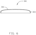
- FIGS. 5 and 6 show that the metallic member 300 to be machined is a housing of a tablet computer or a mobile phone.
- the metallic member 300 is substantially rectangular, and includes a top portion 301 and a peripheral sidewall 303 extending from a peripheral edge of the top portion 301.
- the top portion 301 has a non-symmetrical curved surface with a relatively greater surface area than that of the peripheral sidewall 303.
- the peripheral sidewall 303 has four side surfaces 3031 arranged in order and adjacent two of the four side surfaces 3031 are connected by a corner 3033.
- the four side surfaces 3031 are substantially planar surfaces, each corner 3033 interconnects two adjacent side surfaces 3031.
- the metallic member 300 When in work, the metallic member 300 is placed and held on the worktable 20.
- the worktable 20 drives the metallic member 300 to rotate.
- the metallic member 300 is driven by the second rotating member 27 to rotate around the ⁇ axis.
- the lathe feeding mechanism 40 drives the lathe tool 49 to reciprocate the top portion 301 of the metallic member 300 at a high frequency.
- the pair of first driving mechanisms 35 drive the cross beam 31 to slide along the X-axis
- the second driving mechanism 37 drives the lathe feeding mechanism 40 to move along the Y-axis, until the lathe tool 49 arrives at an original position above the worktable 20 for machining.
- the original position is located above a middle portion of the metallic member 300.
- the second rotating member 27 drives the metallic member 300 to rotate around the ⁇ axis
- the feeding assembly 47 drives the lathe tool 49 to move backwards and forwards at a high speed along the Z-axis according to the depth of cutting required for each machining portion of the top portion 301 to machine the metallic member 300 circumferentially.
- the moving speed of the lathe tool 49 and the rotating speed of the second rotating member 27 is set according to an application.
- a track of the lathe tool 49 projected to a top of the metallic member 300 is a spiral curve.
- the lathe tool 49 moves away from the metallic member 300.
- the milling feeding mechanism 50 drives the milling cutter 57 to rotate and resist the peripheral sidewall 303 of the metallic member 300.
- the pair of first driving mechanisms 35 drives the cross beam 31 to slide along the X-axis
- the second driving mechanism 37 drives the lathe feeding mechanism 40 to move along the Y-axis, such that the milling cutter 57 arrives at a position above an end of one side surface 3031 of the peripheral sidewall 303.
- the linear driving assembly 53 drives the milling cutter 57 to slide along the two sets of guiding rails 413 until the milling cutter 57 resists the peripheral sidewall 303 of the metallic member 300.
- the rotatable driving member 55 drives the milling cutter 57 to rotate, thereby milling the side surface 3031 and the corner 3033.
- the milling feeding mechanism 50 remains still, the worktable 200 rotates the metallic member 300 to enable the milling feeding mechanism 50 to mill the metallic member 300 along the predetermined path.
- the rotatable driving member 55 controls a feed of the milling cutter 57 relative to the metallic member 300 along the Z-axis direction.
- the moving device 30 returns to an original position, and the metallic member 300 is taken out.
- the metallic member 300 is firmly fixed, the milling feeding mechanism 50 automatic mills the metallic member 300 along a predetermined path.
- the rotating member 25 rotates the metallic member 30 along ⁇ axis
- the second rotating member 27 rotates the metallic member 300 along the ⁇ axis, thereby positioning the metallic member 300 in a particular position for machining.
- the lathe feeding mechanism 40 is capable of moving backwards and forwards along the Z-axis toward the metallic member 300 at a high speed, thereby a non-interrupted machining process is achieved, the finish of the top portion 301 is enhanced, additional surface processing to the top portion is omitted.
- the rotatable driving member 55 is capable of driving the milling cutter 57 to rotate, thereby milling the peripheral sidewall 303.
- the metallic member 300 can be machined by the lathe tool 49 and the milling cutter 59 without disassembly/assembly to adapt to different machines, thereby enhancing a position accuracy, a machining efficiency and a yield of the metallic member 300.
- the moving device 30 is capable of moving the lathe feeding mechanism 40 and the milling feeding mechanism 50 along the X/Y directions, the lathe tool 49 and the milling cutter 57 can be moved along Z direction
- the worktable 200 is capable of driving the metallic member 300 to rotate along theaaxis and the ⁇ axis, such that the machining process is more convenient and the machining efficiency is enhanced.
- the machine tool 100 may merely be employed to lathe or mill the metallic member 300.
- the lathe tool 49 may not only machine the top portion 301, but also machine workpiece in other shapes.
- the milling feeding mechanism 50 may not only mill the peripheral sidewall 303, but also mill holes or grooves on the metallic member 300.
- the outer surface of the metallic member 300 only needs to be machined by the milling feeding mechanism 50 to receive a finished surface.
- the feeding assembly 47 may be substituted with other driving assemblies assembled to the pair of second guiding rails 311.
- the driving assembly is capable of directly reciprocating the lathe tool 49 along the Z direction at a high speed.
- the milling feeding mechanism 50 mills the peripheral sidewall 303 of the metallic member 300 before the lathe feeding mechanism 40 machines the top portion 301.
- the worktable 20 may only include the second rotating member 27, the second rotating member 27 is assembled to the base 11, and rotates around the ⁇ axis only.
- the worktable 20 may be a multi-axis worktable, capable of rotating the metallic member 300 along a plurality of axis to enable a multi-workstations machining process.
- FIG. 7 shows a second embodiment of machine tool 200 for machining the metallic member 300.
- the machine tool 200 is similar to the machine tool 100 in structure, a sliding saddle 41a is slidably assembled to a cross beam 31a, and a second rotating member 27a is mounted on a rotating shaft 25a.
- the metallic member 300 is placed and held on the second rotating member 27a.
- the difference between the machine tool 100/200 is that, a mounting seat 43a of the machine tool 200 is slidably mounted on the sliding saddle 41a and capable of sliding along the Z1-axis direction relative to the sliding saddle 41a, and a lathe tool 49a is slidably mounted on the mounting seat 43a.
- the pair of first driving mechanisms 35 drives the cross beam 31 to slide along the X-axis
- the second driving mechanism 37 drives the lathe feeding mechanism 40 to move along the Y-axis, such that the lathe tool 49a arrives at an original position above the worktable 20 for machining.
- the mounting seat 43a drives the lathe tool 49a to move downward along the Z1-axis to reach a preset position near the middle portion of the metallic member 300.
- the feeding assembly 47 drives the lathe tool 49a to reciprocate, cutting at a high speed along the Z-axis according to the depth required for each portion of the top portion 301 machining the rotary metallic member 300 circumferentially.
- the mounting seat 43a can slide along the Z1-aixs to place the lathe tool 49a at the preset position, allowing a reciprocation of the lathe tool 49 relative to the metallic member 300 to be reduced, thereby enhancing a reaction response of the lathe tool 49a.
Description
- The present disclosure generally relates to a machine tool, and particularly, to a machine tool with a lathe tool and a milling cutter.
- An electronic device, such as a tabletop computer or a mobile phone, employs a metallic member as a housing. The metallic member includes a top portion and a peripheral sidewall extending from a peripheral edge of the top portion. The top portion has a greater surface area than that of the peripheral sidewall. The peripheral sidewall has four side surfaces arranged in order and four corners each connecting two adjacent surfaces. In related manufacturing fields, if a milling process is employed to machine the metallic member, some tracks may occur on the top portion that has been a milled because of intermittent contact and interrupted milling of the milling cutter. Then a polishing process needs to be applied to achieve a better appearance. Thus the efficiency of the milling process is reduced. If a lathe process is adapted to machine the metallic member, it may be difficult to tool a surface which is not made for rotating. In addition, the lathe is not suitable to machine the peripheral sidewalls because of the four corners of the peripheral sidewall. Thus a number of additional machining processes must be added to machine the metallic member.
-
EP 1952937 A1 (YAMAZAKI MAZAK CORP [JP], published on 6 August, 2008 ) disclosed a machining center having a first main spindle unit and also a second main spindle unit with a ram shaft attached to a vertical machining center. A machining center comprises a rotary table that moves in the direction X-axis on a bed, and a cross rail supported by a column and moving in the direction of a Z-axis. -
CN 201524905 U (SHENZHEN KANGCHENG MACHINE EQUIPMENT CO LTD, published on 14 July, 2010 ) disclosed a drilling and milling device including a fixed assembly with a drilling shaft and a movable assembly with a milling shaft. The device further includes a board mounted to Z-axis, a sliding board mounted to the board, an auxiliary shaft functioning for connecting the board to the board, a servo motor mounted on the board for driving the shaft. - Therefore, there is room for improvement within the art.
- According to one aspect of the disclosure, a machine tool with lathe tool and milling cutter includes a machine support, a worktable positioned on the machine support, a moving device slidably assembled to the machine support along a first direction and located above the worktable, a lathe feeding mechanism, and a milling feeding mechanism. The lathe feeding mechanism is slidably assembled to the moving device along a second direction perpendicular to the first direction. The lathe feeding mechanism includes a feeding assembly and a lathe tool connected to the feeding assembly. The feeding assembly is configured for driving the lathe tool to move reciprocally along a third direction substantially perpendicular to the first and the second direction. The milling feeding mechanism is slidably assembled to the moving device along a second direction and adjacent to the lathe feeding mechanism. The milling feeding mechanism includes a milling cutter and is configured for driving the milling cutter to move along the third direction.
- The components in the drawings are not necessarily drawn to scale, the emphasis instead placed upon clearly illustrating the principles of the present disclosure. Moreover, in the drawings, like reference numerals designate corresponding parts throughout the several views.
-
FIG. 1 is an isometric view of a first embodiment of a machine tool equipped with a lathe feeding mechanism and a milling feeding mechanism, and a worktable. -
FIG. 2 is an exploded, isometric view of the machine tool ofFIG. 1 . -
FIG. 3 is a partial, exploded, isometric view of the lathe feeding mechanism and the milling feeding mechanism ofFIG. 2 . -
FIG. 4 is an exploded, isometric view of the lathe feeding mechanism ofFIG. 3 . -
FIG. 5 is an isometric view of a metallic member to be machined. -
FIG. 6 is a sectional view of the metallic member ofFIG. 5 , taken along line VI-VI ofFIG. 5 . -
FIG. 7 is a schematic view of a second embodiment of the machine tool with a part thereof being removed. -
FIGS. 1 and2 show a first embodiment of amachine tool 100 adapting a method for machining a metallic member 300 (seeFIG. 5 ). Themachine tool 100 includes amachine support 10, aworktable 20, a movingdevice 30, alathe feeding mechanism 40, amilling feeding mechanism 50, and acontroller 60. Theworktable 20 holds a workpiece in place and is supported by themachine support 10. The movingdevice 30 is movably positioned on themachine support 10 above theworktable 20. Thelathe feeding mechanism 40 and themilling feeding mechanism 50 are arranged side by side and slidably mounted on the movingdevice 30. Thecontroller 60 is electrically connected to theworktable 20, themoving device 30, thelathe feeding mechanism 40, and themilling feeding mechanism 50 for controlling themachine tool 100. Under the control of thecontroller 60, the movingdevice 30 can be driven to move with thelathe feeding mechanism 40 and themilling feeding mechanism 50, such that thelathe feeding mechanism 40 and themilling feeding mechanism 50 can be driven three-dimensionally along Cartesian coordinates, that is, along the X, the Y, and the Z axes. - The
machine support 10 includes abase 11 and a pair of support bodies 13 positioned on thebase 11. The pair of support bodies 13 is parallel to each other and arranged apart from each other. Each support body 13 includes a first slidingrail 131 on a surface away from thebase 11. In the illustrated embodiment, the first slidingrail 131 extends substantially parallel to the X-axis (a first direction). - The
worktable 20 is rotatably positioned on thebase 11 between the two support bodies 13. Theworktable 20 includes a pair ofmounting bases 21, a first rotatingmember 23, a rotatingshaft 25, and a second rotatingmember 27. The pair ofmounting bases 21 is located in the middle portion of thebase 11, in parallel. The pair ofmounting bases 21 is located between the two support bodies 13. The first rotatingmember 23 is mounted on onemounting base 21. The rotatingshaft 25 interconnects the first rotatingmember 23 and the other onemounting base 21. The first rotatingmember 23 is capable of rotating the rotatingshaft 25 around an α axis. The α axis is parallel to the Y-axis but not co-linear (a second direction). The second rotatingmember 27 is positioned on a middle portion of the rotatingshaft 25, and capable of rotating themetallic member 300 placed thereupon around an β axis. The β axis is parallel to the Z-axis (a third direction) but not co-linear. The first rotatingmember 23 and the second rotatingmember 27 are electrically connected to thecontroller 60. In the illustrated embodiment, the first rotatingmember 23 and the second rotatingmember 27 are direct drive motors. - The moving
device 30 is slidably mounted on the pair of support bodies 13 and located above theworktable 20. Themoving device 30 includes across beam 31, a pair ofsliding bases 33, a pair offirst driving mechanisms 35, and asecond driving mechanism 37. The extending direction of thecross beam 31 is substantially parallel to the Y-axis. Opposite ends of thecross beam 31 are slidably positioned on the support bodies 13. Thecross beam 31 includes a pair of second slidingrails 311 positioned on a side surface thereof and extending substantially parallel to the Y-axis. The pair ofsliding bases 33 is installed on the opposite ends of thecross beam 31 to slidably connect with the first slidingrail 131. Thefirst driving mechanism 35 is mounted on a surface of the slidingbase 33 away from thecross beam 31 and located adjacent to an end of the first slidingrail 131. The pair offirst driving mechanisms 35 is employed to drive thecross beam 31 to move along the X-axis direction. - The
second driving mechanism 37 is mounted on the cross beams 31 to drive thelathe feeding mechanism 40 and themilling feeding mechanism 50 to move along the second sliding rails 311. Thefirst driving mechanism 35 and thesecond driving mechanism 37 are electrically connected to thecontroller 60. In the illustrated embodiment, thefirst driving mechanisms 35 and thesecond driving mechanism 37 are linear motors with wonderful performance. In other embodiments, thefirst driving mechanisms 35 and thesecond driving mechanism 37 may be other drivers, such as hydraulic cylinders or rams. The number of thefirst driving mechanisms 35, and thesecond driving mechanism 37 may be set according to the application. -
FIGS. 3 to 4 show thelathe feeding mechanism 40 slidably positioned on the cross beams 31. Thelathe feeding mechanism 40 includes a sliding saddle 41 (seeFIG. 2 ), a mountingseat 43, atool holder 45, a feedingassembly 47, and alathe tool 49. The slidingsaddle 41 is assembled to the cross beams 31 and movably engages with the pair of second sliding rails 311. Thesecond driving mechanism 37 slides along the Y-axis direction together with thelathe feeding mechanism 40 and themilling feeding mechanism 50 to drive the slidingsaddle 41. The slidingsaddle 41 is equipped with four guidingrails 413 extending along the Z-axis direction. The four guidingrails 413 are divided in two sets spaced from each other by two-two type. The slidingsaddle 41 further includes amounting block 415 adjacent to thebase 11. The mountingblock 415 is located between the two sets of guidingrails 413. The mountingseat 43 is assembled to the slidingsaddle 41 and spaced from the four guidingrails 413. - The mounting
seat 43 includes aframe 431 and two mountingboards 433 assembled to opposite sides of theframe 431. Theframe 431 includes a first side wall 4311 and a second side wall 4313. The first side wall 4311 and the second side wall 4313 are positioned substantially parallel to each other and cooperatively define a receiving space 4315. The first side wall 4311 is connected with the slidingsaddle 41. Twoseparate guiding portions 4317 protrude from an inner surface of the first side wall 4311 facing the second side wall 4315 and extend substantially parallel to the Z-axis. A throughgroove 4318 is defined in the second side wall 4313 and extends along a direction substantially parallel to the Z-axis corresponding to the guidingportions 4317. Two slidingportions 4319 protrude from an outer surface of the second side wall 4313 at two sides of the throughgroove 4318. In the illustrated embodiment, the slidingportions 4319 are sliding rails, and theframe 431 is integrally formed. The two mountingboards 433 are installed on two opening sides of theframe 431. Each mountingboard 433 is connected substantially perpendicularly to the first side wall 4311 and the second side wall 4313 to close the two opening sides of theframe 431. - The
tool holder 45 slidably connects with the mountingseat 43. Thetool holder 45 is substantially "T" shaped, and includes amain body 451 and a slidingboard 453 protruding substantially perpendicularly from themain body 451. Themain body 451 is a bar of material tapering at both ends, and positioned outside of the mountingseat 43. Two distanced holdingportions 4511 are positioned on a surface of themain body 451 facing the slidingboard 453. The two holdingportions 4511 slidably engage with the pair of slidingportions 4319 of the mountingseat 43. The slidingboard 453 passes through the throughgroove 4318 and is slidably assembled to the two guidingportions 4317, dividing the receiving space 4315 into two parts. - The feeding
assembly 47 is mounted in the mountingseat 43, and includes twodrivers 471 electrically connected to thecontroller 60. The twodrivers 471 are capable of driving thetool holder 45 into a reciprocating motion at a high speed along the direction of the Z-axis, relative to the guidingportions 4317 and the slidingportions 4319. The twodrivers 471 are received in the receiving space 4315 and are positioned on two sides of the slidingboard 453. In the illustrated embodiment, thedrivers 471 are linear motors. Eachdriver 471 includes a forcer 4711 and a stator 4713. Each forcer 4711 is fixed to a surface of each of the mountingboards 433. The slidingboard 453 is positioned between the two forcers 4711. The two stators 4713 are positioned on the opposite surfaces of the slidingboard 453. In other embodiments, the number ofdrivers 471 may be set according to application. For example, the twodrivers 471 can replace a single driver with more power, or three or more drivers can be positioned to drive thetool holder 45 to maximize the available power, and the assembly of the drivers is simpler. - The
lathe tool 49 is fastened to themain body 451 of thetool holder 4511 adjacent to thebase 11. - The
milling feeding mechanism 50 includes alinear driving assembly 53, a linkingboard 54, arotatable driving member 55 and amilling cutter 57. Thelinear driving assembly 53 includes a drivingmember 531, ascrew leading rod 533, and anut 535. The drivingmember 531 is mounted on the slidingsaddle 43 above thecross beam 31. Thescrew leading rod 533 interconnects the drivingmember 531 and the mountingblock 415. Thenut 535 is sleeved on thescrew leading rod 533 and engages with thescrew leading rod 533. The linkingboard 54 is slidably assembled to the two sets of guidingrails 413 and fixed to thenut 535. The rotatable drivingmember 55 is assembled to a side surface of the linkingboard 54 opposite to thescrew leading rod 533. Themilling cutter 57 is mounted on an end of therotatable driving member 55 adjacent to thebase 11. - The driving
member 531 is capable of rotating thescrew leading rod 533 and driving the linkingboard 54, with therotatable driving member 55, and themilling cutter 57 to slide along Z-axis direction. The rotatable drivingmember 55 is capable of rotating themilling cutter 57 milling themetallic member 300. Themilling cutter 57 is driven by thecross beam 31 to move along the X-axis direction or the Y-axis direction, and driven by the linear drivingassembly 53 to move along Z-axis direction. - In assembly, the
worktable 20 is positioned between the two support bodies 13. Thecross beam 31 is installed on the two support bodies 13 via the pair of slidingbases 33. The pair offirst driving mechanisms 35, and thesecond driving mechanism 37 are mounted on thebase 11 and thecross beam 31, respectively. Thelathe feeding mechanism 40 and themilling feeding mechanism 50 are mounted to thecross beam 31 side by side. Theworktable 20, the movingdevice 30, thelathe feeding mechanism 40, and themilling feeding mechanism 50 are electrically connected to thecontroller 60. -
FIGS. 5 and6 show that themetallic member 300 to be machined is a housing of a tablet computer or a mobile phone. Themetallic member 300 is substantially rectangular, and includes atop portion 301 and aperipheral sidewall 303 extending from a peripheral edge of thetop portion 301. Thetop portion 301 has a non-symmetrical curved surface with a relatively greater surface area than that of theperipheral sidewall 303. In the embodiment, theperipheral sidewall 303 has fourside surfaces 3031 arranged in order and adjacent two of the fourside surfaces 3031 are connected by acorner 3033. The fourside surfaces 3031 are substantially planar surfaces, eachcorner 3033 interconnects two adjacent side surfaces 3031. - When in work, the
metallic member 300 is placed and held on theworktable 20. Theworktable 20 drives themetallic member 300 to rotate. In the embodiment, themetallic member 300 is driven by the second rotatingmember 27 to rotate around the β axis. Thelathe feeding mechanism 40 drives thelathe tool 49 to reciprocate thetop portion 301 of themetallic member 300 at a high frequency. In detail, first, the pair offirst driving mechanisms 35 drive thecross beam 31 to slide along the X-axis, and thesecond driving mechanism 37 drives thelathe feeding mechanism 40 to move along the Y-axis, until thelathe tool 49 arrives at an original position above theworktable 20 for machining. In the embodiment, the original position is located above a middle portion of themetallic member 300. Finally, the second rotatingmember 27 drives themetallic member 300 to rotate around the β axis, simultaneously, the feedingassembly 47 drives thelathe tool 49 to move backwards and forwards at a high speed along the Z-axis according to the depth of cutting required for each machining portion of thetop portion 301 to machine themetallic member 300 circumferentially. The moving speed of thelathe tool 49 and the rotating speed of the second rotatingmember 27 is set according to an application. A track of thelathe tool 49 projected to a top of themetallic member 300 is a spiral curve. - The
lathe tool 49 moves away from themetallic member 300. Themilling feeding mechanism 50 drives themilling cutter 57 to rotate and resist theperipheral sidewall 303 of themetallic member 300. In detail, firstly, the pair offirst driving mechanisms 35 drives thecross beam 31 to slide along the X-axis, and thesecond driving mechanism 37 drives thelathe feeding mechanism 40 to move along the Y-axis, such that themilling cutter 57 arrives at a position above an end of oneside surface 3031 of theperipheral sidewall 303. Second, the linear drivingassembly 53 drives themilling cutter 57 to slide along the two sets of guidingrails 413 until themilling cutter 57 resists theperipheral sidewall 303 of themetallic member 300. Finally, therotatable driving member 55 drives themilling cutter 57 to rotate, thereby milling theside surface 3031 and thecorner 3033. Themilling feeding mechanism 50 remains still, theworktable 200 rotates themetallic member 300 to enable themilling feeding mechanism 50 to mill themetallic member 300 along the predetermined path. The rotatable drivingmember 55 controls a feed of themilling cutter 57 relative to themetallic member 300 along the Z-axis direction. When finished, the movingdevice 30 returns to an original position, and themetallic member 300 is taken out. In another embodiment, themetallic member 300 is firmly fixed, themilling feeding mechanism 50 automatic mills themetallic member 300 along a predetermined path. In addition, when a particular portion of themetallic member 300 is to be machined, the rotatingmember 25 rotates themetallic member 30 along α axis, the second rotatingmember 27 rotates themetallic member 300 along the β axis, thereby positioning themetallic member 300 in a particular position for machining. - The
lathe feeding mechanism 40 is capable of moving backwards and forwards along the Z-axis toward themetallic member 300 at a high speed, thereby a non-interrupted machining process is achieved, the finish of thetop portion 301 is enhanced, additional surface processing to the top portion is omitted. The rotatable drivingmember 55 is capable of driving themilling cutter 57 to rotate, thereby milling theperipheral sidewall 303. Themetallic member 300 can be machined by thelathe tool 49 and the milling cutter 59 without disassembly/assembly to adapt to different machines, thereby enhancing a position accuracy, a machining efficiency and a yield of themetallic member 300. Because the movingdevice 30 is capable of moving thelathe feeding mechanism 40 and themilling feeding mechanism 50 along the X/Y directions, thelathe tool 49 and themilling cutter 57 can be moved along Z direction, theworktable 200 is capable of driving themetallic member 300 to rotate along theaaxis and theβaxis, such that the machining process is more convenient and the machining efficiency is enhanced. - The
machine tool 100 may merely be employed to lathe or mill themetallic member 300. Thelathe tool 49 may not only machine thetop portion 301, but also machine workpiece in other shapes. Themilling feeding mechanism 50 may not only mill theperipheral sidewall 303, but also mill holes or grooves on themetallic member 300. The outer surface of themetallic member 300 only needs to be machined by themilling feeding mechanism 50 to receive a finished surface. - other embodiments, the feeding
assembly 47 may be substituted with other driving assemblies assembled to the pair of second guiding rails 311. The driving assembly is capable of directly reciprocating thelathe tool 49 along the Z direction at a high speed. - The
milling feeding mechanism 50 mills theperipheral sidewall 303 of themetallic member 300 before thelathe feeding mechanism 40 machines thetop portion 301. - In some embodiments, the
worktable 20 may only include the second rotatingmember 27, the second rotatingmember 27 is assembled to thebase 11, and rotates around theβaxis only. Theworktable 20 may be a multi-axis worktable, capable of rotating themetallic member 300 along a plurality of axis to enable a multi-workstations machining process. -
FIG. 7 shows a second embodiment ofmachine tool 200 for machining themetallic member 300. Themachine tool 200 is similar to themachine tool 100 in structure, a sliding saddle 41a is slidably assembled to across beam 31a, and a secondrotating member 27a is mounted on a rotating shaft 25a. Themetallic member 300 is placed and held on the second rotatingmember 27a. The difference between themachine tool 100/200 is that, a mounting seat 43a of themachine tool 200 is slidably mounted on the sliding saddle 41a and capable of sliding along the Z1-axis direction relative to the sliding saddle 41a, and a lathe tool 49a is slidably mounted on the mounting seat 43a. - When the
lathe feeding mechanism 40 is to machine thetop portion 301 of themetallic member 300, the pair offirst driving mechanisms 35 drives thecross beam 31 to slide along the X-axis, and thesecond driving mechanism 37 drives thelathe feeding mechanism 40 to move along the Y-axis, such that the lathe tool 49a arrives at an original position above theworktable 20 for machining. Then the mounting seat 43a drives the lathe tool 49a to move downward along the Z1-axis to reach a preset position near the middle portion of themetallic member 300. Finally, the feedingassembly 47 drives the lathe tool 49a to reciprocate, cutting at a high speed along the Z-axis according to the depth required for each portion of thetop portion 301 machining the rotarymetallic member 300 circumferentially. The mounting seat 43a can slide along the Z1-aixs to place the lathe tool 49a at the preset position, allowing a reciprocation of thelathe tool 49 relative to themetallic member 300 to be reduced, thereby enhancing a reaction response of the lathe tool 49a. - While the present disclosure has been described with reference to particular embodiments, the description is illustrative of the disclosure and is not to be construed as limiting the disclosure. Therefore, various modifications can be made to the embodiments by those of ordinary skill in the art without departing from the scope of the disclosure, as defined by the appended claims.
Claims (9)
- A machine tool (100) with a lathe tool (49) and a milling cutter (57), the machine tool (100) comprising:a machine support (10);a worktable (20) positioned on the machine support (10);a moving device (30) slidably assembled to the machine support (10) along a first direction and located above the worktable (20);a lathe feeding mechanism (40) slidably assembled to the moving device (30) along a second direction perpendicular to the first direction, the lathe feeding mechanism (40) comprising a feeding assembly (47) and a lathe tool (49) connected to the feeding assembly (47); anda milling feeding mechanism (50) slidably assembled to the moving device (30) along the second direction and adjacent to the lathe feeding mechanism (40), the milling feeding mechanism (50) comprising a milling cutter (57) and configured for driving the milling cutter (57) to move along a third direction substantially perpendicular to the first and the second direction,wherein the lathe tool (47) is driven to move backwards and forwards at high speed along the third direction by the feeding assembly (47) when lathing a surface of a workpiece;_and wherein the lathe feeding mechanism (40) further comprises a sliding saddle (41), the sliding saddle (41) is slidably connected to the moving device (30) along the second direction, the milling feeding mechanism (50) is slidably mounted on the sliding saddle (41); the milling feeding mechanism (50) comprises a linear driving assembly (53) and the rotatable driving member (531), the linear driving assembly (53) mounted on the sliding saddle (41), the rotatable driving member (531) is connected to the linear driving assembly (53), the linear driving assembly (53) drives the rotatable driving member (531) and the milling cutter (57) to move along the third direction and to adjust feed of the milling cutter (57) relative to a metallic member (300), the rotatable driving member (531) is capable of driving the milling cutter (57) to rotatethe sliding saddle (41) comprises a mounting block (415), the linear driving assembly (53) comprises a driving member (531), a screw leading rod (533), and a nut (535), the driving member (531) is mounted on the sliding saddle (41), the screw leading rod (533) interconnects the driving member (531) and the mounting block (415), the nut (535) is sleeved on and engages with the screw leading rod (533).
- The machine tool of claim 1, wherein the lathe feeding mechanism (40) further comprises a mounting seat (43) fittingly assembled to the sliding saddle (41), the feeding assembly (47) is received in the mounting seat (43), and the lathe tool (47) is slidably mounted on the mounting seat (43), the milling feeding mechanism (50) is adjacent to the mounting seat (43), the lathe tool (47) is capable of moving along the third direction relative to the mounting seat (43).
- The machine tool of claim 2, wherein the milling feeding mechanism (50) further comprises a linking board (54) fixed to the nut (535) and slidably engages with the sliding saddle (41), the rotatable driving member (531) is fittingly assembled to the linking board (54).
- The machine tool of claim 3, wherein the sliding saddle (41) further comprises two sets of guiding rails (413), the mounting block (415) is located between the two sets of guiding rails (413), the linking board (54) is slidably assembled to each of the two sets of guiding rails (413).
- The machine tool of any of claims 2 to 4, wherein the lathe feeding mechanism (40) further comprises a tool holder (45), the mounting seat (43) comprises a pair of guiding portions (4317) extending along the third direction, the tool holder (45) is slidably assembled to each of the pair of guiding portions (4317), the lathe tool (47) is mounted on the tool holder (45).
- The machine tool of claim 5, wherein the tool holder (45) comprises a main body (451) and a sliding board (453) protruding substantially perpendicularly from the main body (451), the main body (451) is positioned out of the mounting seat (43), the sliding board (453) is received in the mounting seat (43) and is slidably assembled to each of the pair of guiding portions (4317), the lathe tool (47) is mounted on the main body (451).
- The machine tool of claim 6, wherein the feeding assembly (47) comprises at least one forcer (4711) and at least one stator (4713) correspondingly located relative to the at least one forcer (4711), the at least one forcer (4711) is fixed to mounting seat (43), the at least one stator (4713) is positioned on the sliding board (453).
- The machine tool of any of claims 1 to 7, wherein the worktable (20) is capable of rotating along an axis parallel to the third direction.
- The machine tool of claim 8, wherein the worktable (20) comprises a pair of mounting bases (21), a first rotating member (23), a rotating shaft (25), and a second rotating member (27), the first rotating member (23) is mounted on one of the two mounting bases (21), the rotating shaft (25) interconnects the first rotating member (23) and another one of the two mounting bases (21), the second rotating member (27) is positioned on the rotating shaft (27) and capable of rotating along the axis parallel to the third direction, the first rotating member (23) is capable of rotating the rotating shaft (25) along an axis parallel to the second direction.
Applications Claiming Priority (1)
| Application Number | Priority Date | Filing Date | Title |
|---|---|---|---|
| CN201210554105.2A CN103878590A (en) | 2012-12-19 | 2012-12-19 | Machine tool |
Publications (3)
| Publication Number | Publication Date |
|---|---|
| EP2745958A2 EP2745958A2 (en) | 2014-06-25 |
| EP2745958A3 EP2745958A3 (en) | 2015-01-21 |
| EP2745958B1 true EP2745958B1 (en) | 2022-02-09 |
Family
ID=49766970
Family Applications (1)
| Application Number | Title | Priority Date | Filing Date |
|---|---|---|---|
| EP13197293.7A Active EP2745958B1 (en) | 2012-12-19 | 2013-12-13 | Machine tool with lathe tool and milling cutter |
Country Status (5)
| Country | Link |
|---|---|
| US (1) | US9409268B2 (en) |
| EP (1) | EP2745958B1 (en) |
| JP (1) | JP6457176B2 (en) |
| CN (1) | CN103878590A (en) |
| TW (1) | TWI485032B (en) |
Families Citing this family (37)
| Publication number | Priority date | Publication date | Assignee | Title |
|---|---|---|---|---|
| CN103878592B (en) * | 2012-12-19 | 2017-06-06 | 鸿准精密模具(昆山)有限公司 | Lathe |
| CN103878636B (en) * | 2012-12-19 | 2018-05-04 | 鸿准精密模具(昆山)有限公司 | Machine tool control system |
| CN104096861B (en) * | 2014-07-04 | 2017-01-11 | 福建成功机床有限公司 | Double-tool-rest dual-channel numerically-controlled vertical lathe |
| BG2292U1 (en) * | 2014-10-20 | 2016-10-31 | "Ред Стиил" ЕООД | Machine for processing of volumetric metal objects |
| CN105619076A (en) * | 2014-10-28 | 2016-06-01 | 富鼎电子科技(嘉善)有限公司 | Combined machining device |
| CN105058060A (en) * | 2015-08-25 | 2015-11-18 | 五莲县长泰工贸有限公司 | Turning, drilling and milling combined machine tool for machining flange |
| US9649695B1 (en) * | 2016-03-10 | 2017-05-16 | Meridian Equipment, Inc. | Automated cross slide system |
| CN105619077A (en) * | 2016-03-11 | 2016-06-01 | 中山市鸿程科研技术服务有限公司 | Milling mechanism of multifunctional automatic processing all-in-one machine |
| JP6099787B1 (en) * | 2016-03-24 | 2017-03-22 | 株式会社牧野フライス製作所 | Cutting method and machine tool |
| WO2017167089A1 (en) * | 2016-03-28 | 2017-10-05 | 广东长盈精密技术有限公司 | Turning/milling system and turning/milling method |
| CN107538225A (en) * | 2016-06-24 | 2018-01-05 | 金元庆 | Brill grinding machine tool is attacked in turnning and milling boring |
| CN106270685A (en) * | 2016-08-26 | 2017-01-04 | 蚌埠市勇创机械电子有限公司 | A kind of dust-collecting type circuit board groove milling system |
| CN108058030A (en) * | 2016-09-07 | 2018-05-22 | 深圳市瑞德森智能设备有限责任公司 | Lathe headstock moving structure and lathe |
| CN106217064A (en) * | 2016-09-07 | 2016-12-14 | 深圳市瑞德森智能设备有限责任公司 | A kind of lathe headstock moving structure and lathe |
| CN106514261B (en) * | 2016-12-20 | 2018-09-21 | 安徽汉采密封件科技有限公司 | milling device |
| CN107350810B (en) * | 2017-05-15 | 2019-04-23 | 温州昌佳阀门有限公司 | The turnning and milling face of a kind of ball valve body and valve deck carries cooling multistation turnning and milling molding machine |
| CN106975962A (en) * | 2017-06-05 | 2017-07-25 | 东莞汉为智能技术有限公司 | Abnormal curved surface high speed feed machining tool |
| CN107138781A (en) * | 2017-06-28 | 2017-09-08 | 南通福通机床有限公司 | A kind of itself profiling machine of surface of steel plate |
| DE102017216446A1 (en) * | 2017-09-17 | 2019-03-21 | Deckel Maho Seebach Gmbh | Machine tool for machining a workpiece |
| CN109865847A (en) * | 2017-12-04 | 2019-06-11 | 油机机械工业(中国)有限公司 | NC vertical lathe with two-sided tumbling function |
| DE102018201419A1 (en) * | 2018-01-30 | 2019-08-01 | Deckel Maho Pfronten Gmbh | machine tool |
| CN108247476A (en) * | 2018-01-31 | 2018-07-06 | 广东豪特曼智能机器有限公司 | Mobile phone 3D ceramics rear cover special vertical grinding machine and its method for grinding |
| CN108274239A (en) * | 2018-04-08 | 2018-07-13 | 周辉 | Combined machine |
| CN110385464A (en) * | 2018-04-19 | 2019-10-29 | 上海胜僖汽车配件有限公司 | A kind of long short side integration device for deburring of die casting cover board |
| CN109176694A (en) * | 2018-09-18 | 2019-01-11 | 东莞市手拉手智能装备有限公司 | A kind of pcb board board separator |
| CN111113044A (en) * | 2018-10-31 | 2020-05-08 | 富鼎电子科技(嘉善)有限公司 | Composite processing device |
| CN109605046A (en) * | 2018-12-28 | 2019-04-12 | 江西吉米立机械科技有限公司 | A kind of numerical control mill vehicle combined machine |
| US10722953B1 (en) * | 2019-01-18 | 2020-07-28 | Feng-Tien Chen | CNC milling machine combined with picking robotic arm unit |
| CN110039095A (en) * | 2019-04-08 | 2019-07-23 | 科德数控股份有限公司 | A kind of horizontal five axis turnover panel machining center |
| CN112475397B (en) * | 2019-08-22 | 2022-07-15 | 温岭市华中数控机床有限公司 | Anticollision sword digit control machine tool |
| CN110480073B (en) * | 2019-09-23 | 2023-11-28 | 翟泉来 | High-speed wheel rail locomotive body beam end cutting machine |
| TWI776172B (en) * | 2020-06-22 | 2022-09-01 | 陳鵬任 | Small Gantry Overhead Processing Machine |
| CN112238381A (en) * | 2020-07-29 | 2021-01-19 | 天津林凯数控机床有限公司 | Following grinding device and method for triple eccentric butterfly valve |
| CN112496415A (en) * | 2020-11-27 | 2021-03-16 | 江苏科马特机械有限公司 | Numerical control drilling and milling machine tool with vibration eliminating frame |
| CN114192652B (en) * | 2021-12-18 | 2023-11-10 | 温岭市大精模具有限公司 | Machining center for production of stamping die |
| CN114700742B (en) * | 2022-04-02 | 2023-06-30 | 富翔精密工业(昆山)有限公司 | Turning milling device |
| CN114986091B (en) * | 2022-05-20 | 2023-09-15 | 上海云明汽车部件有限公司 | Process and equipment for manufacturing fuel common rail |
Family Cites Families (41)
| Publication number | Priority date | Publication date | Assignee | Title |
|---|---|---|---|---|
| DE2753386A1 (en) * | 1977-11-30 | 1979-05-31 | Horst Dr Zimmermann | MACHINE TOOL |
| US4570313A (en) * | 1984-12-31 | 1986-02-18 | G. A. Gray Division, The Warner & Swasey Company | Spindle lock-up device |
| JPH04105831A (en) * | 1990-08-28 | 1992-04-07 | Toshiba Mach Co Ltd | Composite machine tool |
| FR2743015B1 (en) * | 1995-12-29 | 1998-03-27 | Helis Sa | MOBILE GANTRY MACHINE WITH MOVABLE UPRIGHTS IN RELATION TO EACH OTHER |
| DE19650360A1 (en) * | 1996-10-28 | 1998-05-07 | Wurst Karl Heinz Dr Ing | Drive unit for machine tool |
| JP3167644B2 (en) * | 1997-06-20 | 2001-05-21 | 株式会社森精機製作所 | Tool spindle fixing device for compound machine tools |
| JP2000158256A (en) | 1998-11-26 | 2000-06-13 | Matsuura Machinery Corp | Compound working device |
| JP2001198702A (en) * | 2000-01-12 | 2001-07-24 | Dainichi Kinzoku Kogyo Kk | Composite working machine |
| DE10029967B4 (en) * | 2000-06-26 | 2006-08-03 | Satisloh Gmbh | Device for processing optical workpieces |
| DE10225514B4 (en) | 2002-06-10 | 2005-02-17 | Kadia Produktion Gmbh + Co. | Machine for the finest machining of workpieces by honing or fine grinding |
| US7089835B2 (en) * | 2002-07-03 | 2006-08-15 | Cdm Optics, Inc. | System and method for forming a non-rotationally symmetric portion of a workpiece |
| JP2004130468A (en) | 2002-10-11 | 2004-04-30 | Mitsui Seiki Kogyo Co Ltd | Machine tool |
| US7544025B2 (en) * | 2005-02-16 | 2009-06-09 | Cross Hüller GmbH | Double-spindle machine tool |
| ATE380090T1 (en) * | 2005-02-23 | 2007-12-15 | Kessler Kg Maschf | PROCESSING MACHINE WITH SEVERAL PARALLEL SPINDLE ARRANGEMENTS |
| TWM276644U (en) * | 2005-03-11 | 2005-10-01 | Annn Yang Machinery Co Ltd | Vertical lathe with milling machine |
| TWM286741U (en) * | 2005-04-22 | 2006-02-01 | Myday Machine Inc | Action column type compound machining center |
| JP2007000966A (en) * | 2005-06-23 | 2007-01-11 | O M Ltd | Machine tool |
| JP5030606B2 (en) | 2007-01-30 | 2012-09-19 | ヤマザキマザック株式会社 | Machining center |
| JP2008246594A (en) * | 2007-03-29 | 2008-10-16 | Fujinon Corp | Machining data calculating method of free curved surface and manufacturing method of free curved surface |
| CN101157255B (en) * | 2007-11-12 | 2011-11-16 | 沈阳建筑大学 | Multifunctional stone machining center with 8-axes 5-linkage function |
| CN201217147Y (en) * | 2008-06-25 | 2009-04-08 | 南通福通机床有限公司 | Deflection shaft transmission numerical control double-post vertical vehicle milling and drilling machine |
| CN101357490B (en) * | 2008-09-01 | 2011-11-16 | 沈阳建筑大学 | Irregular stone multifunctional composite processing center with double five-axle linkage system |
| CN101412185A (en) | 2008-11-25 | 2009-04-22 | 鲜于哲善 | Numerical control drilling-milling apparatus having a plurality of independent process systems |
| CN201524905U (en) | 2009-02-09 | 2010-07-14 | 深圳市康铖机械设备有限公司 | Small portal double main shaft drilling and milling numerically-controlled machine tool |
| CN101870063B (en) * | 2009-04-24 | 2012-06-20 | 上海电机学院 | Vertical five axle interlocked gantry digital control milling machining center |
| EP2263827B1 (en) | 2009-06-16 | 2012-01-04 | MAG IAS GmbH | Machine tool for processing workpieces |
| CN201483235U (en) * | 2009-09-09 | 2010-05-26 | 沈阳大兴机床有限责任公司 | Multifunction machine tool |
| CN201603999U (en) * | 2009-11-03 | 2010-10-13 | 王瑞增 | Numerical control turning, milling, drilling, grinding and boring combined machining center |
| DE102009058649A1 (en) | 2009-12-16 | 2011-06-22 | Adams, Heinz, 66740 | Drilling-milling machine has additional rotary tool-carriage that is horizontally arranged on milling carriage in movable manner, where rotary tool holders are arranged with rotary tools before milling head |
| DE102011105402A1 (en) | 2011-06-20 | 2012-12-20 | Heinz Adams | Milling, turning, grinding machine for workpiece, has vertically movable vertical milling-turning slide and vertically movable vertical grinding rotary plunger movably vertically installed adjacent to each other on Y-bar slide |
| CN202192431U (en) * | 2011-07-01 | 2012-04-18 | 沈阳机床(集团)有限责任公司 | Mechanical numerical-control double-shaft rotary table equipment |
| CN202180208U (en) * | 2011-07-14 | 2012-04-04 | 油机机械工业(昆山)有限公司 | Numerical-control vertical lathe with double-surface cutting function |
| CN103878635B (en) * | 2012-12-19 | 2018-05-04 | 鸿准精密模具(昆山)有限公司 | Machine tool control system |
| CN103878535B (en) * | 2012-12-19 | 2016-06-08 | 鸿准精密模具(昆山)有限公司 | Metalwork processing method |
| CN103878592B (en) * | 2012-12-19 | 2017-06-06 | 鸿准精密模具(昆山)有限公司 | Lathe |
| CN103878534B (en) * | 2012-12-19 | 2016-05-11 | 鸿准精密模具(昆山)有限公司 | Metalwork processing method |
| CN103878424B (en) * | 2012-12-19 | 2016-12-28 | 鸿准精密模具(昆山)有限公司 | Metalwork processing method |
| CN103878636B (en) * | 2012-12-19 | 2018-05-04 | 鸿准精密模具(昆山)有限公司 | Machine tool control system |
| CN103878588B (en) * | 2012-12-19 | 2016-08-03 | 鸿准精密模具(昆山)有限公司 | Metalwork processing method |
| CN103878591B (en) * | 2012-12-19 | 2016-12-28 | 鸿准精密模具(昆山)有限公司 | Metalwork processing method |
| CN103878589B (en) * | 2012-12-19 | 2016-12-28 | 鸿准精密模具(昆山)有限公司 | Metalwork processing method |
-
2012
- 2012-12-19 CN CN201210554105.2A patent/CN103878590A/en active Pending
- 2012-12-25 TW TW101149927A patent/TWI485032B/en not_active IP Right Cessation
-
2013
- 2013-11-04 US US14/070,705 patent/US9409268B2/en active Active
- 2013-12-13 JP JP2013257975A patent/JP6457176B2/en active Active
- 2013-12-13 EP EP13197293.7A patent/EP2745958B1/en active Active
Also Published As
| Publication number | Publication date |
|---|---|
| EP2745958A3 (en) | 2015-01-21 |
| JP2014121777A (en) | 2014-07-03 |
| CN103878590A (en) | 2014-06-25 |
| TW201424924A (en) | 2014-07-01 |
| EP2745958A2 (en) | 2014-06-25 |
| TWI485032B (en) | 2015-05-21 |
| US9409268B2 (en) | 2016-08-09 |
| US20140165348A1 (en) | 2014-06-19 |
| JP6457176B2 (en) | 2019-01-23 |
Similar Documents
| Publication | Publication Date | Title |
|---|---|---|
| EP2745958B1 (en) | Machine tool with lathe tool and milling cutter | |
| EP2745959B1 (en) | Machine tool with lathe tool and scraping cutter | |
| EP2745961B1 (en) | Method for machining metallic member using lathing and milling | |
| US9381580B2 (en) | Milling method for machining metallic member | |
| US9630278B2 (en) | Method for machining metallic member using lathing and scraping | |
| US9550257B2 (en) | Method for machining metallic member using lathing and milling | |
| EP2687307B1 (en) | Method for machining curved surface using lathe | |
| US9381607B2 (en) | Feeding device and machine tool using the same | |
| US8881626B2 (en) | Lathe for machining curved surfaces | |
| US9346143B2 (en) | Lathe for machining curved surfaces | |
| US9718153B2 (en) | Method for machining metallic member using lathing and scraping | |
| US9254542B2 (en) | Machine tool with uninterrupted cutting | |
| EP2745960B1 (en) | Method for machining metallic member using lathing and milling | |
| US9757824B2 (en) | Method for machining metallic member using lathing and scraping | |
| EP2687308B1 (en) | Lathe for machining curved surfaces | |
| RU38126U1 (en) | METAL-CUTTING MACHINE FOR INTEGRATED FIVE-ORDER PROCESSING | |
| US9238306B2 (en) | Feeding device and machine tool using the same | |
| EP2745962B1 (en) | Method for machining metallic member using lathing and scraping | |
| EP2687324B1 (en) | Feeding device and machine tool using the same |
Legal Events
| Date | Code | Title | Description |
|---|---|---|---|
| PUAI | Public reference made under article 153(3) epc to a published international application that has entered the european phase |
Free format text: ORIGINAL CODE: 0009012 |
|
| 17P | Request for examination filed |
Effective date: 20131213 |
|
| AK | Designated contracting states |
Kind code of ref document: A2 Designated state(s): AL AT BE BG CH CY CZ DE DK EE ES FI FR GB GR HR HU IE IS IT LI LT LU LV MC MK MT NL NO PL PT RO RS SE SI SK SM TR |
|
| AX | Request for extension of the european patent |
Extension state: BA ME |
|
| PUAL | Search report despatched |
Free format text: ORIGINAL CODE: 0009013 |
|
| AK | Designated contracting states |
Kind code of ref document: A3 Designated state(s): AL AT BE BG CH CY CZ DE DK EE ES FI FR GB GR HR HU IE IS IT LI LT LU LV MC MK MT NL NO PL PT RO RS SE SI SK SM TR |
|
| AX | Request for extension of the european patent |
Extension state: BA ME |
|
| RIC1 | Information provided on ipc code assigned before grant |
Ipc: B23B 3/00 20060101AFI20141218BHEP Ipc: B23P 23/02 20060101ALI20141218BHEP |
|
| R17P | Request for examination filed (corrected) |
Effective date: 20150721 |
|
| RBV | Designated contracting states (corrected) |
Designated state(s): AL AT BE BG CH CY CZ DE DK EE ES FI FR GB GR HR HU IE IS IT LI LT LU LV MC MK MT NL NO PL PT RO RS SE SI SK SM TR |
|
| STAA | Information on the status of an ep patent application or granted ep patent |
Free format text: STATUS: EXAMINATION IS IN PROGRESS |
|
| 17Q | First examination report despatched |
Effective date: 20190322 |
|
| STAA | Information on the status of an ep patent application or granted ep patent |
Free format text: STATUS: EXAMINATION IS IN PROGRESS |
|
| RIN1 | Information on inventor provided before grant (corrected) |
Inventor name: YU, JIAN-MIN Inventor name: LIU, YI Inventor name: LI, JIEE Inventor name: ZHUANG, DA-QING Inventor name: SUI, JING-SHUANG Inventor name: XU, ZHEN-GUANG Inventor name: CHEN, FENG-HUA Inventor name: QU, JIAN Inventor name: PENG, YANG-MAO Inventor name: JIA, JIAN-SHI Inventor name: ZHANG, WEI-CHUAN Inventor name: ZHANG,TIAN-EN Inventor name: YANG, MING-LU |
|
| GRAP | Despatch of communication of intention to grant a patent |
Free format text: ORIGINAL CODE: EPIDOSNIGR1 |
|
| STAA | Information on the status of an ep patent application or granted ep patent |
Free format text: STATUS: GRANT OF PATENT IS INTENDED |
|
| INTG | Intention to grant announced |
Effective date: 20210924 |
|
| RIN1 | Information on inventor provided before grant (corrected) |
Inventor name: YU, JIAN-MIN Inventor name: LIU, YI Inventor name: LI, JIE Inventor name: ZHUANG, DA-QING Inventor name: SUI, JING-SHUANG Inventor name: XU, ZHEN-GUANG Inventor name: CHEN, FENG-HUA Inventor name: QU, JIAN Inventor name: PENG, YANG-MAO Inventor name: JIA, JIAN-SHI Inventor name: ZHANG, WEI-CHUAN Inventor name: ZHANG,TIAN-EN Inventor name: YANG, MING-LU |
|
| GRAS | Grant fee paid |
Free format text: ORIGINAL CODE: EPIDOSNIGR3 |
|
| GRAA | (expected) grant |
Free format text: ORIGINAL CODE: 0009210 |
|
| STAA | Information on the status of an ep patent application or granted ep patent |
Free format text: STATUS: THE PATENT HAS BEEN GRANTED |
|
| AK | Designated contracting states |
Kind code of ref document: B1 Designated state(s): AL AT BE BG CH CY CZ DE DK EE ES FI FR GB GR HR HU IE IS IT LI LT LU LV MC MK MT NL NO PL PT RO RS SE SI SK SM TR |
|
| REG | Reference to a national code |
Ref country code: GB Ref legal event code: FG4D |
|
| REG | Reference to a national code |
Ref country code: CH Ref legal event code: EP Ref country code: AT Ref legal event code: REF Ref document number: 1467195 Country of ref document: AT Kind code of ref document: T Effective date: 20220215 |
|
| REG | Reference to a national code |
Ref country code: IE Ref legal event code: FG4D |
|
| REG | Reference to a national code |
Ref country code: DE Ref legal event code: R096 Ref document number: 602013080865 Country of ref document: DE |
|
| REG | Reference to a national code |
Ref country code: LT Ref legal event code: MG9D |
|
| REG | Reference to a national code |
Ref country code: NL Ref legal event code: MP Effective date: 20220209 |
|
| REG | Reference to a national code |
Ref country code: AT Ref legal event code: MK05 Ref document number: 1467195 Country of ref document: AT Kind code of ref document: T Effective date: 20220209 |
|
| PG25 | Lapsed in a contracting state [announced via postgrant information from national office to epo] |
Ref country code: SE Free format text: LAPSE BECAUSE OF FAILURE TO SUBMIT A TRANSLATION OF THE DESCRIPTION OR TO PAY THE FEE WITHIN THE PRESCRIBED TIME-LIMIT Effective date: 20220209 Ref country code: RS Free format text: LAPSE BECAUSE OF FAILURE TO SUBMIT A TRANSLATION OF THE DESCRIPTION OR TO PAY THE FEE WITHIN THE PRESCRIBED TIME-LIMIT Effective date: 20220209 Ref country code: PT Free format text: LAPSE BECAUSE OF FAILURE TO SUBMIT A TRANSLATION OF THE DESCRIPTION OR TO PAY THE FEE WITHIN THE PRESCRIBED TIME-LIMIT Effective date: 20220609 Ref country code: NO Free format text: LAPSE BECAUSE OF FAILURE TO SUBMIT A TRANSLATION OF THE DESCRIPTION OR TO PAY THE FEE WITHIN THE PRESCRIBED TIME-LIMIT Effective date: 20220509 Ref country code: NL Free format text: LAPSE BECAUSE OF FAILURE TO SUBMIT A TRANSLATION OF THE DESCRIPTION OR TO PAY THE FEE WITHIN THE PRESCRIBED TIME-LIMIT Effective date: 20220209 Ref country code: LT Free format text: LAPSE BECAUSE OF FAILURE TO SUBMIT A TRANSLATION OF THE DESCRIPTION OR TO PAY THE FEE WITHIN THE PRESCRIBED TIME-LIMIT Effective date: 20220209 Ref country code: HR Free format text: LAPSE BECAUSE OF FAILURE TO SUBMIT A TRANSLATION OF THE DESCRIPTION OR TO PAY THE FEE WITHIN THE PRESCRIBED TIME-LIMIT Effective date: 20220209 Ref country code: ES Free format text: LAPSE BECAUSE OF FAILURE TO SUBMIT A TRANSLATION OF THE DESCRIPTION OR TO PAY THE FEE WITHIN THE PRESCRIBED TIME-LIMIT Effective date: 20220209 Ref country code: BG Free format text: LAPSE BECAUSE OF FAILURE TO SUBMIT A TRANSLATION OF THE DESCRIPTION OR TO PAY THE FEE WITHIN THE PRESCRIBED TIME-LIMIT Effective date: 20220509 |
|
| PG25 | Lapsed in a contracting state [announced via postgrant information from national office to epo] |
Ref country code: PL Free format text: LAPSE BECAUSE OF FAILURE TO SUBMIT A TRANSLATION OF THE DESCRIPTION OR TO PAY THE FEE WITHIN THE PRESCRIBED TIME-LIMIT Effective date: 20220209 Ref country code: LV Free format text: LAPSE BECAUSE OF FAILURE TO SUBMIT A TRANSLATION OF THE DESCRIPTION OR TO PAY THE FEE WITHIN THE PRESCRIBED TIME-LIMIT Effective date: 20220209 Ref country code: GR Free format text: LAPSE BECAUSE OF FAILURE TO SUBMIT A TRANSLATION OF THE DESCRIPTION OR TO PAY THE FEE WITHIN THE PRESCRIBED TIME-LIMIT Effective date: 20220510 Ref country code: FI Free format text: LAPSE BECAUSE OF FAILURE TO SUBMIT A TRANSLATION OF THE DESCRIPTION OR TO PAY THE FEE WITHIN THE PRESCRIBED TIME-LIMIT Effective date: 20220209 Ref country code: AT Free format text: LAPSE BECAUSE OF FAILURE TO SUBMIT A TRANSLATION OF THE DESCRIPTION OR TO PAY THE FEE WITHIN THE PRESCRIBED TIME-LIMIT Effective date: 20220209 |
|
| PG25 | Lapsed in a contracting state [announced via postgrant information from national office to epo] |
Ref country code: IS Free format text: LAPSE BECAUSE OF FAILURE TO SUBMIT A TRANSLATION OF THE DESCRIPTION OR TO PAY THE FEE WITHIN THE PRESCRIBED TIME-LIMIT Effective date: 20220609 |
|
| PG25 | Lapsed in a contracting state [announced via postgrant information from national office to epo] |
Ref country code: SM Free format text: LAPSE BECAUSE OF FAILURE TO SUBMIT A TRANSLATION OF THE DESCRIPTION OR TO PAY THE FEE WITHIN THE PRESCRIBED TIME-LIMIT Effective date: 20220209 Ref country code: SK Free format text: LAPSE BECAUSE OF FAILURE TO SUBMIT A TRANSLATION OF THE DESCRIPTION OR TO PAY THE FEE WITHIN THE PRESCRIBED TIME-LIMIT Effective date: 20220209 Ref country code: RO Free format text: LAPSE BECAUSE OF FAILURE TO SUBMIT A TRANSLATION OF THE DESCRIPTION OR TO PAY THE FEE WITHIN THE PRESCRIBED TIME-LIMIT Effective date: 20220209 Ref country code: EE Free format text: LAPSE BECAUSE OF FAILURE TO SUBMIT A TRANSLATION OF THE DESCRIPTION OR TO PAY THE FEE WITHIN THE PRESCRIBED TIME-LIMIT Effective date: 20220209 Ref country code: DK Free format text: LAPSE BECAUSE OF FAILURE TO SUBMIT A TRANSLATION OF THE DESCRIPTION OR TO PAY THE FEE WITHIN THE PRESCRIBED TIME-LIMIT Effective date: 20220209 Ref country code: CZ Free format text: LAPSE BECAUSE OF FAILURE TO SUBMIT A TRANSLATION OF THE DESCRIPTION OR TO PAY THE FEE WITHIN THE PRESCRIBED TIME-LIMIT Effective date: 20220209 |
|
| REG | Reference to a national code |
Ref country code: DE Ref legal event code: R097 Ref document number: 602013080865 Country of ref document: DE |
|
| PG25 | Lapsed in a contracting state [announced via postgrant information from national office to epo] |
Ref country code: AL Free format text: LAPSE BECAUSE OF FAILURE TO SUBMIT A TRANSLATION OF THE DESCRIPTION OR TO PAY THE FEE WITHIN THE PRESCRIBED TIME-LIMIT Effective date: 20220209 |
|
| PLBE | No opposition filed within time limit |
Free format text: ORIGINAL CODE: 0009261 |
|
| STAA | Information on the status of an ep patent application or granted ep patent |
Free format text: STATUS: NO OPPOSITION FILED WITHIN TIME LIMIT |
|
| 26N | No opposition filed |
Effective date: 20221110 |
|
| PG25 | Lapsed in a contracting state [announced via postgrant information from national office to epo] |
Ref country code: SI Free format text: LAPSE BECAUSE OF FAILURE TO SUBMIT A TRANSLATION OF THE DESCRIPTION OR TO PAY THE FEE WITHIN THE PRESCRIBED TIME-LIMIT Effective date: 20220209 |
|
| PG25 | Lapsed in a contracting state [announced via postgrant information from national office to epo] |
Ref country code: IT Free format text: LAPSE BECAUSE OF FAILURE TO SUBMIT A TRANSLATION OF THE DESCRIPTION OR TO PAY THE FEE WITHIN THE PRESCRIBED TIME-LIMIT Effective date: 20220209 |
|
| REG | Reference to a national code |
Ref country code: CH Ref legal event code: PL |
|
| REG | Reference to a national code |
Ref country code: BE Ref legal event code: MM Effective date: 20221231 |
|
| PG25 | Lapsed in a contracting state [announced via postgrant information from national office to epo] |
Ref country code: LU Free format text: LAPSE BECAUSE OF NON-PAYMENT OF DUE FEES Effective date: 20221213 |
|
| PG25 | Lapsed in a contracting state [announced via postgrant information from national office to epo] |
Ref country code: LI Free format text: LAPSE BECAUSE OF NON-PAYMENT OF DUE FEES Effective date: 20221231 Ref country code: IE Free format text: LAPSE BECAUSE OF NON-PAYMENT OF DUE FEES Effective date: 20221213 Ref country code: CH Free format text: LAPSE BECAUSE OF NON-PAYMENT OF DUE FEES Effective date: 20221231 |
|
| PG25 | Lapsed in a contracting state [announced via postgrant information from national office to epo] |
Ref country code: BE Free format text: LAPSE BECAUSE OF NON-PAYMENT OF DUE FEES Effective date: 20221231 |
|
| PGFP | Annual fee paid to national office [announced via postgrant information from national office to epo] |
Ref country code: GB Payment date: 20231221 Year of fee payment: 11 |
|
| PGFP | Annual fee paid to national office [announced via postgrant information from national office to epo] |
Ref country code: FR Payment date: 20231221 Year of fee payment: 11 Ref country code: DE Payment date: 20231219 Year of fee payment: 11 |
|
| PG25 | Lapsed in a contracting state [announced via postgrant information from national office to epo] |
Ref country code: HU Free format text: LAPSE BECAUSE OF FAILURE TO SUBMIT A TRANSLATION OF THE DESCRIPTION OR TO PAY THE FEE WITHIN THE PRESCRIBED TIME-LIMIT; INVALID AB INITIO Effective date: 20131213 |