EP2745331B1 - Verteilermessdose zur strangstrombestimmung in photovoltaikanlagen - Google Patents
Verteilermessdose zur strangstrombestimmung in photovoltaikanlagen Download PDFInfo
- Publication number
- EP2745331B1 EP2745331B1 EP12751263.0A EP12751263A EP2745331B1 EP 2745331 B1 EP2745331 B1 EP 2745331B1 EP 12751263 A EP12751263 A EP 12751263A EP 2745331 B1 EP2745331 B1 EP 2745331B1
- Authority
- EP
- European Patent Office
- Prior art keywords
- junction
- box
- connection
- measurement box
- string
- Prior art date
- Legal status (The legal status is an assumption and is not a legal conclusion. Google has not performed a legal analysis and makes no representation as to the accuracy of the status listed.)
- Not-in-force
Links
Images


Classifications
-
- H—ELECTRICITY
- H02—GENERATION; CONVERSION OR DISTRIBUTION OF ELECTRIC POWER
- H02S—GENERATION OF ELECTRIC POWER BY CONVERSION OF INFRARED RADIATION, VISIBLE LIGHT OR ULTRAVIOLET LIGHT, e.g. USING PHOTOVOLTAIC [PV] MODULES
- H02S50/00—Monitoring or testing of PV systems, e.g. load balancing or fault identification
-
- H—ELECTRICITY
- H10—SEMICONDUCTOR DEVICES; ELECTRIC SOLID-STATE DEVICES NOT OTHERWISE PROVIDED FOR
- H10F—INORGANIC SEMICONDUCTOR DEVICES SENSITIVE TO INFRARED RADIATION, LIGHT, ELECTROMAGNETIC RADIATION OF SHORTER WAVELENGTH OR CORPUSCULAR RADIATION
- H10F77/00—Constructional details of devices covered by this subclass
- H10F77/95—Circuit arrangements
- H10F77/953—Circuit arrangements for devices having potential barriers
- H10F77/955—Circuit arrangements for devices having potential barriers for photovoltaic devices
-
- G—PHYSICS
- G01—MEASURING; TESTING
- G01R—MEASURING ELECTRIC VARIABLES; MEASURING MAGNETIC VARIABLES
- G01R15/00—Details of measuring arrangements of the types provided for in groups G01R17/00 - G01R29/00, G01R33/00 - G01R33/26 or G01R35/00
- G01R15/14—Adaptations providing voltage or current isolation, e.g. for high-voltage or high-current networks
- G01R15/20—Adaptations providing voltage or current isolation, e.g. for high-voltage or high-current networks using galvano-magnetic devices, e.g. Hall-effect devices, i.e. measuring a magnetic field via the interaction between a current and a magnetic field, e.g. magneto resistive or Hall effect devices
-
- H—ELECTRICITY
- H02—GENERATION; CONVERSION OR DISTRIBUTION OF ELECTRIC POWER
- H02G—INSTALLATION OF ELECTRIC CABLES OR LINES, OR OF COMBINED OPTICAL AND ELECTRIC CABLES OR LINES
- H02G3/00—Installations of electric cables or lines or protective tubing therefor in or on buildings, equivalent structures or vehicles
- H02G3/02—Details
- H02G3/08—Distribution boxes; Connection or junction boxes
- H02G3/081—Bases, casings or covers
- H02G3/083—Inlets
-
- H—ELECTRICITY
- H02—GENERATION; CONVERSION OR DISTRIBUTION OF ELECTRIC POWER
- H02G—INSTALLATION OF ELECTRIC CABLES OR LINES, OR OF COMBINED OPTICAL AND ELECTRIC CABLES OR LINES
- H02G3/00—Installations of electric cables or lines or protective tubing therefor in or on buildings, equivalent structures or vehicles
- H02G3/02—Details
- H02G3/08—Distribution boxes; Connection or junction boxes
- H02G3/16—Distribution boxes; Connection or junction boxes structurally associated with support for line-connecting terminals within the box
-
- H—ELECTRICITY
- H02—GENERATION; CONVERSION OR DISTRIBUTION OF ELECTRIC POWER
- H02S—GENERATION OF ELECTRIC POWER BY CONVERSION OF INFRARED RADIATION, VISIBLE LIGHT OR ULTRAVIOLET LIGHT, e.g. USING PHOTOVOLTAIC [PV] MODULES
- H02S50/00—Monitoring or testing of PV systems, e.g. load balancing or fault identification
- H02S50/10—Testing of PV devices, e.g. of PV modules or single PV cells
-
- Y—GENERAL TAGGING OF NEW TECHNOLOGICAL DEVELOPMENTS; GENERAL TAGGING OF CROSS-SECTIONAL TECHNOLOGIES SPANNING OVER SEVERAL SECTIONS OF THE IPC; TECHNICAL SUBJECTS COVERED BY FORMER USPC CROSS-REFERENCE ART COLLECTIONS [XRACs] AND DIGESTS
- Y02—TECHNOLOGIES OR APPLICATIONS FOR MITIGATION OR ADAPTATION AGAINST CLIMATE CHANGE
- Y02E—REDUCTION OF GREENHOUSE GAS [GHG] EMISSIONS, RELATED TO ENERGY GENERATION, TRANSMISSION OR DISTRIBUTION
- Y02E10/00—Energy generation through renewable energy sources
- Y02E10/50—Photovoltaic [PV] energy
Definitions
- the invention relates to a decentralized current determination in photovoltaic systems in an electrical junction box for a photovoltaic solar module.
- a shunt resistor is installed in a generator switch box for each string, at which the current amount of the string line can be measured.
- this method is disadvantageous in that for each single strand, the strand line must be routed separately up to the generator control box, which leads to high costs due to the cable lengths required.
- Such a central current measurement in a generator switch box is also disadvantageous in that the heat output released by the plurality of shunt resistors in the current measurement has to be dissipated from the generator switch box. If necessary, this requires the use of cooling fans, whose power consumption further reduces the total yield of the Phtovoltaikgenerators.
- German utility model DE 20 2005 018 884 U1 is exemplary to take a conventional junction box for a solar panel. With such a conventional junction box no strand current measurement is feasible.
- German patent application DE 10 2008 008 503 A1 For example, a conventional PV sub-generator junction box for a central current measurement can be seen, which has the aforementioned disadvantages.
- the font US 2010/0300509 A1 discloses a current measuring method for a photovoltaic solar module.
- the invention therefore has the task of solving the above problems or to reduce.
- Yet another object of the invention is to provide a redundant phase current measuring system for each strand of the photovoltaic generator for measuring the respective phase current.
- Another object of the invention is to shorten cable lengths of the strand lines.
- a distribution box which houses an extraneous current measuring module for measuring the single-strand currents.
- the distribution box has a rear support portion, which is designed in particular for resting on a photovoltaic solar module, a circumferential side wall and a lid.
- the peripheral side wall of the distribution box has openings to guide the end of a branch line or a short box line into the interior of the distribution box or to contact at or in the opening.
- the rear support section is prepared in particular for gluing.
- the distribution box further has inside a strand current measuring module with a measuring component and an am Measuring component arranged measuring electronics, in particular a voltage or current measuring device on.
- the strand current measuring module comprises a sensor for measuring the electrical string current and an evaluation device for evaluating a characteristic of the sensor and can therefore be referred to as a current measuring transducer.
- the electrical distribution box is preferably mounted directly on the bottom of a solar module.
- the installation of the distribution box directly on the sun-facing underside of a solar module protects the distribution box from the weather. Moreover, this can simplify the installation in the case of new plants, since the distribution boxes before installation of the solar modules simply attached to the rear part of the solar modules, e.g. can be glued.
- Such an arrangement is a simple solution for retrofitting already manufactured solar modules, to which a connection and junction box, in which the emerging from the solar module electrical conductor strips, is already attached, with the distribution box according to the invention.
- the electrical connection of the distribution box is done for example on the one hand by means of a socket connection line which is connected to the connection and connection box of the solar module, and on the other side by means of a short doses line, at the end of a strand connector is attached, or by a strand line is led directly through the cable entry in the distribution box.
- a socket connection line which is connected to the connection and connection box of the solar module, and on the other side by means of a short doses line, at the end of a strand connector is attached, or by a strand line is led directly through the cable entry in the distribution box.
- the distribution box with the junction box and the distribution box can also be plugged directly to the connection and junction box, in particular by means of a measuring socket connector. In the case of direct plugging the distribution box is therefore arranged directly adjacent to the connection and junction box.
- two separate cans are applied to a solar module and electrically connected to each other, wherein the electrical connection is made either by means of a doses line between the cans or by means of a measuring jack connector.
- the strand current measuring module and the electrical conductor strips emerging from the solar module can be integrated in a common electrical distribution box.
- the terminal of the photovoltaic solar module is arranged in the distribution box next to the strand current measuring module.
- the connection of the photovoltaic solar module comprises the electrical conductor strips emerging from the solar module, which discharge the electrical power generated by the solar module to the conductor line.
- this is a modified connection and connection box for a solar module, wherein the strand current measuring module is integrated in the connection and connection box to be mounted on the solar module.
- connection and junction box comprises a support section formed on the solar module for support.
- connection and junction box comprises an electrical connection and connection device with an input-side connection element for electrically contacting the conductor strips on the one hand and with an output-side connection element for electrically contacting the doses line or the strand line on the other hand, for example, terminals to the electrical connection between the Conductor bands and the strand lines, when the junction box is attached to the solar module.
- connection and junction box helps to reduce manufacturing costs by saving components, such as two separate socket housings and additional external connecting leads.
- the electrical loss caused by the strand current measuring module can be further reduced by carrying out the measurement of the electrical current, for example, directly at the connection and connection device for the conductor strips emerging from the solar module.
- connection and connection device has two each via a rigid Bridge element interconnected contact terminals for releasably connecting the conductor strips on the one hand and the strand line on the other.
- the rigid bridge element is in particular made in one piece, for example a stamped and shaped metal part, in order to further reduce the electrical loss.
- the strand current measuring module has, in one embodiment, a shunt resistor and a voltage measuring device on the shunt resistor, the shunt resistor and the voltage measuring device preferably being accommodated in the connection and connection socket.
- the shunt resistor is preferably integrated into the rigid bridge element for connecting the strand line to the conductor strip of the solar module, so that the connection elements are connected to one another via the shunt resistor. This can reduce the power loss and the production cost, since less or more compact electrical components can be used.
- the strand current measuring module comprises a Hall sensor and an associated Hall probe for potential-free measurement of the phase current.
- the Hall sensor preferably comprises a toroidal core for a magnetic flux measurement and is in particular attached to the rigid bridge element of the connection and connection device or to the cable entry of the distribution box.
- a magnetoresistive sensor for measuring the phase current is included in the strand current measuring module.
- the magnetoresistive sensor may, for example, be attached to the rigid bridge element of the connection and connection device or to the stranded bushing of the distribution box.
- the magnetoresistive sensor enables a low-loss current measurement, whereby only a small amount of heat has to be produced and dissipated.
- the magnetoresistive sensor is inexpensive to manufacture. Just in the integration of the magnetoresistive sensor in the connection and junction box, no further contacts or components which intervene in the current flow of the solar module or interrupt the flow of current are required, which can cause further power loss.
- the use of the magnetoresistive sensor or the Hall sensor accordingly makes it possible to deliver the useful energy from the solar system to downstream inverters even in the event of a fault of the measuring electronics.
- the magnetoresistive sensor is mounted directly on the rigid bridge element of the connection and connection device or on one of the strands of the distribution box. Attachment to the ducting of the distribution box is also possible in the event that the distribution box is not the junction box of the solar module in which the conductor strips are housed.
- the magnetoresistive In particular, the sensor has such a small size that the design of the connection and connection box of the photovoltaic solar module does not have to be changed.
- the solar system can continue to operate without disruption even in case of failure of a sensor and further the strand current can be measured by the characteristic of another strand current measuring module of the same strand is read.
- the electrical power required for the measurement of the electrical parameter by means of the strand current measuring module is in particular obtained directly from the solar module or the generator train, on or in which the strand current measuring module is arranged. This eliminates the need for additional wiring for the power supply of the strand current measuring modules.
- a further embodiment of the distribution measuring box comprises a radio transmission device for transmitting the value of the characteristic variable measured by the strand current measuring module to a central evaluation device. These data can also be transmitted via the power cables themselves ("PowerLine communication"). Both methods provide a simple and reliable readout of the measurement data generated by the strand current measurement module.
- a photovoltaic system with a plurality of photovoltaic solar modules, wherein the photovoltaic solar modules are equipped with junction boxes and wherein in each strand of the photovoltaic system at least one arranged on a solar module in a distribution box strand current measuring module is used to measure the strand current.
- such a photovoltaic system has a central evaluation device, by means of which the measured values generated by the strand current measuring modules can be detected and evaluated.
- a central evaluation device is a workstation computer, which has a receiving and / or transmission means, which can be connected to the strand current measuring module of the distribution box.
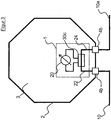
- distribution box 2 has an underside, which is designed to rest on a solar module and thus forms a support portion 3.
- the support portion 3 may have mounting holes or be provided for a bond.
- the Distribution box 2 further has a circumferential side wall 5, in which openings 4 for the passage or connection of the strand lines, can lines or the measuring cell connection line 10, 10a, 12 are provided.
- a stranded line can be passed through a stranded bushing 4a, and a stranded pipe 4b can be connected to a stranded wire connector 4b, for example, by means of a connector.
- a line connector 4b is inserted.
- the strand line 10 connects a first pole of the photovoltaic generator with the distribution box 2
- the load cell connection line 10a connects the distribution box with the connection and junction box of the solar module and further with a second electrical pole of the photovoltaic generator, possibly between the respective pole and the Distribution box 2 more solar modules can be located.
- the distribution box 2 accommodates an extraneous current measuring module 1.
- a doses line 22 is connected to the string connector 4b and with the other end to a measuring component 30, the string line 10 is connected to the string connector 4b. It can also be provided to pass the stranded line 10 through the stranded bushing 4 a and to contact the measuring component 30 directly with its end, or to install the socketed strand 22 preassembled through the stranded bushing 4 a to the outside and to equip it outside the distribution box 2 with a plug, so that the strand line 10 is electrically contacted outside the distribution box 2.
- the connection solution suitable for the individual case.
- the measuring component 30 is in the embodiment of FIG. 1 a shunt resistor 30a, at which the voltage drop is measured by means of a voltmeter 20. On the basis of the measured voltage value U and the known resistance value R of the shunt resistor 30a, the current I flowing through the shunt resistor 30a can be determined.
- Another doses line 24 connects the output of the shunt resistor 30a with the line connector 4b, so that with the load cell connection line 10a a connection with the connection and connection box of the solar module and subsequently with the second pole of the photovoltaic generator or with other solar modules is possible.
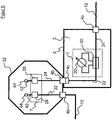
- the distribution box 2 comprises a ring core, which works as a Hall sensor 30b. At the toroidal core, a voltmeter 20 is connected.
- FIG. 3 shows a preferred embodiment of the invention, wherein as a measuring component 30, a magnetoresistive sensor 30c is used.
- the magnetoresistive sensor 30c surrounds the electrical line in such a way that the eddy currents surrounding the electrical conductor are detected.
- the voltage measurement by means of the Magnetoresistive sensor 30c non-invasive, ie, that the strand line is not interrupted by the strand current measuring module 1 and a particularly low-resistance measurement takes place.
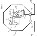
- FIG. 4 shows an embodiment with two separate housings, the distribution box 2 with the strand current measuring module 1 and the connection and junction box 32, in which the emerging from the solar module electrical conductor strips 42 are contacted.
- the embodiment thus shows the use of with FIGS. 1 to 3 distribution boxes shown in connection with the connection and junction box.
- connection and junction box 32 emerging from the solar module electrical conductor strips 42, which are connected to contacts 44 of the solar module or at the point indicated by the numeral 44 emerge from the solar module, contacted.
- the conductor strips 42 are each connected to a connection element 28 of the connection and connection device 7.
- a first stranded line 10 connects a first electrical pole of the photovoltaic generator through the stranded bushing 4a directly to the first connection element 28 in the junction box and the first conductor strip 42.
- the stranded line 10 is limited to approximately the dimensions of the solar module and has on external end of a plug for connecting to another strand line or with another solar module.
- the electrical current flow passes through the photovoltaic solar module and the individual Solar cells via the second conductor strip 42 and the second connection element 28, to the load cell connection line 10 a, which connects through the cable duct 4 a through the junction box 32 with the distribution box 2.
- the strand current measuring module 1 is housed.
- the further construction of the distribution box is identical to that in FIG. 3 shown construction.
- a second branch line 12 finally connects the distribution box 2 with the second electrical pole of the photovoltaic generator.
- This embodiment of the invention is particularly suitable for retrofitting existing solar modules or for retrofitting already installed solar systems.
- the distribution box 2 in a simple manner on the already installed solar modules in addition to the existing connection and junction box 32 can be glued or otherwise secured on the underside and the electrical contact of the first branch line 12 are connected to the retrofitted distribution box 2.
- the further limited to the back of this solar module load cell connection line 10a is connected to the existing connection and junction box 32 (see. Fig. 7 ). Another installation effort is not necessary.
- FIG. 5 shows an embodiment of the invention with two separate housings, wherein the distribution box 2 is electrically connected to the connection and junction box 32 via a measuring jack connector 4c.
- the load cell connector 4c is made pairable with the strand connector 4b, wherein in shown example of the measuring socket connector 4c in the distribution box 2 and the strand connector 4b is housed in the connection and junction box.
- the distribution box 2 is therefore directly plugged into the connection and junction box 32.
- the distribution box 2 and the connection and junction box 32 are in this embodiment in the assembled state immediately adjacent.
- the measuring socket connector 4c is in this case plugged together with the string connector 4b. In this example, therefore, can be dispensed with the measuring cell connection line 10a.
- the distribution box 2 is also in this embodiment as in the Fig. 3 shown example with line connectors 4b for the connection of the strand lines 10, 12 equipped.
- FIG. 6 shows a further embodiment of the invention, wherein in the distribution box 2 at the same time emerging from the solar module electrical conductor strips 42, which are connected to contacts 44 of the solar module or emerge at the point indicated by the numeral 44 point out of the solar module to be contacted.
- the conductor strips 42 are each connected to a connection element 28 of the connection and connection device.
- the connection element 28 is connected to the strand lines 10, 12 at a further end by means of the box branch lines 22, 24.
- an electrical circuit is formed by the first stranded line 10 via the doses line 22, the conductor strips 42, the doses line 24 and the other branch line 12.
- the strand current measuring module 1 is also housed.
- the strand current measuring module 1 comprises, in the illustrated embodiment, the magnetoresistive sensor 30c to which the voltage measuring device 20 is connected for measuring the voltage induced at the magnetoresistive sensor 30c.
- connection device for a solar module in a distribution box 2 is housed in a particularly advantageous manner.
- the distribution box 2 at the same time also the connection and junction box 32 of the solar module. This reduces production, logistics and assembly costs.
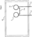
- FIG. 7 shows the mounted on a solar module 40 on the bottom side state of distribution box 2 and connection and junction box 32.
- the first strand line 12 is connected in the embodiment shown with the distribution box 2, the limited to the dimensions of this solar module measuring cell connection line 10a connects the junction box 2 with the terminal - And junction box 32, and the strand line 10 finally connects the second electrical pole of the photovoltaic generator with the connection and junction box 32nd
Landscapes
- Photovoltaic Devices (AREA)
- Physics & Mathematics (AREA)
- General Physics & Mathematics (AREA)
- Life Sciences & Earth Sciences (AREA)
- Engineering & Computer Science (AREA)
- Sustainable Development (AREA)
- Sustainable Energy (AREA)
Description
- Die Erfindung betrifft eine dezentrale Strangstrombestimmung in Photovoltaikanlagen in einer elektrischen Verteilerdose für ein photovoltaisches Solarmodul.
- Bei einem Photovoltaikgenerator einer Photovoltaikanlage ist es sinnvoll, eine Strangstrommessung der einzelnen Photovoltaikgeneratorstränge durchzuführen. Die Kenntnis der Einzelstrangströme ermöglicht Rückschlüsse über die Ausbeute der Solarmodule der Einzelstränge und ist ein Indikator für Störungen in der Anlage, wie beispielsweise der Ausfall einzelner Solarmodule.
- Üblicherweise ist hierfür in einem Generatorschaltkasten für jeden Strang ein Shuntwiderstand eingebaut, an welchem der Strombetrag der Strangleitung gemessen werden kann. Dies ist zwar ein verbreitet angewendetes Verfahren, es weist aber einige Nachteile auf, für die keine zufriedenstellenden Lösungen zu finden sind.
- So ist diesem Verfahren nachteilig, dass für jeden Einzelstrang die Strangleitung bis zu dem Generatorschaltkasten getrennt geführt werden muss, was zu hohen Kosten aufgrund der benötigten Kabellängen führt.
- Einer solchen zentralen Strommessung in einem Generatorschaltkasten ist ferner nachteilig, dass die durch die mehreren Shuntwiderstände bei der Strommessung freigesetzte Wärmeleistung aus dem Generatorschaltkasten abgeführt werden muss. Gegebenenfalls erfordert dies die Verwendung von Kühlungslüftern, deren Stromverbrauch den Gesamtertrag des Phtovoltaikgenerators weiter reduziert.
- Ein Grund für die Strangstrommessung in dem Generatorschaltkasten ist die feuchtigkeitsgeschützte Unterbringung der für die Strangstrommessung benötigten Bauteile.
- Insbesondere bei Photovoltaikanlagen mit einem großen und damit leistungsstarken Photovoltaikgenerator, oder bei langen Kabelstrecken zwischen dem Photovoltaikgenerator und dem Generatorschaltkasten, sind signifikant höhere Kosten durch einen solchen Aufbau aufgrund der Kabelstrecken zu berücksichtigen. Des Weiteren rufen lange Kabelstrecken für jedes Kabel einen Verlust hervor.
- Bei der Verwendung von Strommessmodulen zum Einbau in den Photovoltaikgeneratoranschlusskasten entstehen dem Anwender darüber hinaus weitere Kosten, da diese Module zusätzlich zu erwerben und in den Generatoranschlusskasten einzubauen sind.
- Dem deutschen Gebrauchsmuster
DE 20 2005 018 884 U1 ist beispielhaft eine herkömmliche Anschlussdose für ein Solarpaneel zu entnehmen. Mit einer solchen herkömmlichen Anschlussdose ist keine Strangstrommessung durchführbar. - Der deutschen Offenlegungsschrift
DE 10 2008 008 503 A1 ist beispielhaft ein herkömmlicher PV-Teilgenerator-Anschlusskasten für eine zentrale Strommessung zu entnehmen, der die zuvor genannten Nachteile aufweist. - Die Schrift
US 2010/0300509 A1 offenbart ein Strommessverfahren für ein photovoltaisches Solarmodul. - Die Erfindung hat sich daher die Aufgabe gestellt, die genannten Probleme zu lösen oder zu mindern.
- Noch eine Aufgabe der Erfindung ist es, zur Messung des jeweiligen Strangstromes ein redundantes Strangstrommesssystem für jeden Strang des Photovoltaikgenerators zur Verfügung zu stellen.
- Eine weitere Aufgabe der Erfindung ist es, Kabelstrecken der Strangleitungen zu verkürzen.
- Die Aufgabe der Erfindung wird durch den Gegenstand der unabhängigen Ansprüche gelöst. Vorteilhafte Weiterbildungen der Erfindung sind in den Unteransprüchen definiert.
- Erfindungsgemäß wird eine Verteilermessdose bereitgestellt, welche ein Strangstrommessmodul zur Messung der Einzelstrangströme beherbergt. Die Verteilermessdose weist einen rückseitigen Auflageabschnitt, der insbesondere zur Auflage auf einem photovoltaischen Solarmodul ausgebildet ist, eine umlaufende Seitenwand sowie einen Deckel auf. Die umlaufende Seitenwand der Verteilermessdose weist Öffnungen auf, um das Ende einer Strangleitung oder eine kurze Dosenstrangleitung ins Innere der Verteilermessdose zu führen oder an bzw. in der Öffnung zu kontaktieren. Der rückseitige Auflageabschnitt ist insbesondere für eine Klebung vorbereitet.
- Die Verteilermessdose weist ferner im Inneren ein Strangstrommessmodul mit einem Messbauteil sowie einer am Messbauteil angeordneten Messelektronik, insbesondere einem Spannungs- oder Strommessgerät, auf. Mit anderen Worten umfasst das Strangstrommessmodul einen Sensor zur Messung des elektrischen Strangstromes sowie eine Auswerteeinrichtung zum Auswerten einer Kenngröße des Sensors und kann demnach als Strommessumformer bezeichnet werden.
- Die elektrische Verteilermessdose ist bevorzugt direkt auf der Unterseite eines Solarmoduls angebracht. Die Anbringung der Verteilermessdose direkt auf der sonnenabgewandten Unterseite eines Solarmoduls schützt die Verteilermessdose vor Witterungseinflüssen. Darüber hinaus kann dies die Installation im Falle von Neuanlagen vereinfachen, da die Verteilermessdosen vor der Installation der Solarmodule einfach am rückwärtigen Teil der Solarmodule angebracht, z.B. geklebt werden können. Eine solche Anordnung ist eine einfache Lösung zur Nachrüstung von bereits gefertigten Solarmodulen, an welchen eine Anschluss- und Verbindungsdose, in welche die aus dem Solarmodul heraustretenden elektrischen Leiterbänder eintreten, bereits angebracht ist, mit der erfindungsgemäßen Verteilermessdose.
- Die elektrische Verbindung der Verteilermessdose erfolgt z.B. auf der einen Seite mittels einer Dosenverbindungsleitung, die an die Anschluss- und Verbindungsdose des Solarmoduls angeschlossen wird, und auf der anderen Seite mittels einer kurzen Dosenstrangleitung, an deren Ende ein Strangleitungsstecker angebracht ist, oder indem die eine Strangleitung direkt durch die Strangleitungsdurchführung in die Verteilermessdose geführt wird. Zur elektrischen Verbindung der Verteilermessdose mit der Anschluss- und Verbindungsdose kann die Verteilermessdose auch unmittelbar an die Anschluss- und Verbindungsdose angesteckt werden, insbesondere mittels eines Messdosensteckverbinders. Im Falle des unmittelbaren Ansteckens ist die Verteilermessdose demnach zu der Anschluss- und Verbindungsdose direkt benachbart angeordnet.
- Mit anderen Worten werden hierbei zwei getrennte Dosen auf ein Solarmodul aufgebracht und miteinander elektrisch verbunden, wobei die elektrische Verbindung entweder mittels einer Dosenstrangleitung zwischen den Dosen oder mittels eines Messdosensteckverbinders hergestellt wird.
- In einer besonders bevorzugten Ausführungsform können das Strangstrommessmodul und die aus dem Solarmodul heraustretenden elektrischen Leiterbänder in einer gemeinsamen elektrischen Verteilermessdose integriert werden. In dieser bevorzugten Ausführungsform der Erfindung ist in der Verteilermessdose neben dem Strangstrommessmodul auch der Anschluss des photovoltaischen Solarmoduls angeordnet. Der Anschluss des photovoltaischen Solarmoduls umfasst die aus dem Solarmodul heraustretenden elektrischen Leiterbänder, welche die von dem Solarmodul erzeugte elektrische Leistung an die Strangleitung abführen. Mit anderen Worten handelt es sich dabei um eine modifizierte Anschluss- und Verbindungsdose für ein Solarmodul, wobei in die auf das Solarmodul anzubringende Anschluss- und Verbindungsdose das Strangstrommessmodul integriert ist.
- Eine solche Anschluss- und Verbindungsdose umfasst ein zur Auflage auf dem Solarmodul ausgebildeten Auflageabschnitt.
- Des Weiteren umfasst eine solche Anschluss- und Verbindungsdose eine elektrische Anschluss- und Verbindungseinrichtung mit einem eingangsseitigen Anschlusselement zum elektrischen Kontaktieren der Leiterbänder einerseits und mit einem ausgangsseitigen Anschlusselement zum elektrischen Kontaktieren der Dosenstrangleitung oder der Strangleitung andererseits, jeweils beispielsweise Anschlussklemmen, um die elektrische Verbindung zwischen den Leiterbändern und den Strangleitungen herzustellen, wenn die Anschluss- und Verbindungsdose an dem Solarmodul angebracht ist.
- Die integrierte Anordnung des Strangstrommessmoduls sowie des Anschlusses des Solarmoduls in einer Anschluss- und Verbindungsdose hilft, Fertigungskosten zu verringern, indem Bauteile eingespart werden, wie beispielsweise zwei getrennte Dosengehäuse und zusätzliche externe Verbindungsleitungen.
- Überdies kann durch die Anbringung des Strangstrommessmoduls im Bereich der Leiterbänder des Solarmoduls der durch das Strangstrommessmodul hervorgerufene elektrische Verlust weiter verringert werden, indem die Messung des elektrischen Stromes beispielsweise direkt an der Anschluss- und Verbindungseinrichtung für die aus dem Solarmodul heraustretenden Leiterbänder durchgeführt wird.
- In einer bevorzugten Ausführungsform des Strangstrommessmoduls in der Anschluss- und Verbindungsdose des photovoltaischen Solarmoduls weist die Anschluss- und Verbindungseinrichtung je zwei über ein starres Brückenelement miteinander verbundene Kontaktklemmen zum lösbaren Anschließen der Leiterbänder einerseits und der Strangleitung andererseits auf. Mittels der Kontaktklemmen ist ein schnelles und sicheres Verbinden der Leiterbänder des Solarmoduls mit den Strangleitungen in der Anschluss- und Verbindungsdose ermöglicht. Das starre Brückenelement ist insbesondere einstückig ausgeführt, z.B. ein gestanztes und geformtes Metallteil, um den elektrischen Verlust weiter zu verringern.
- Das Strangstrommessmodul weist in einer Ausführungsform einen Shuntwiderstand sowie eine Spannungsmesseinrichtung am Shuntwiderstand auf, wobei der Shuntwiderstand und die Spannungsmesseinrichtung vorzugsweise in der Anschluss- und Verbindungsdose beherbergt sind. Der Shuntwiderstand ist vorzugsweise in das starre Brückenelement zur Verbindung der Strangleitung mit dem Leiterband des Solarmoduls integriert, so dass die Anschlusselemente über den ShuntWiderstand miteinander verbunden sind. Dies kann die Verlustleistung und den Fertigungsaufwand verringern, da weniger bzw. kompaktere elektrische Bauteile eingesetzt werden können.
- In einer weiteren Ausführungsform umfasst das Strangstrommessmodul einen Hallsensor und eine zugehörige Hallsonde zur potentialfreien Messung des Strangstromes. Der Hallsensor umfasst vorzugsweise einen Ringkern für eine magnetische Flussmessung und ist insbesondere an dem starren Brückenelement der Anschluss- und Verbindungseinrichtung oder an der Strangleitungsdurchführung der Verteilermessdose angebracht.
- Besonders bevorzugt ist in dem Strangstrommessmodul ein magnetoresistiver Sensor zur Messung des Strangstromes umfasst. Der magnetoresistive Sensor kann beispielsweise an dem starren Brückenelement der Anschluss- und Verbindungseinrichtung oder an der Strangleitungsdurchführung der Verteilermessdose angebracht sein. Insgesamt ermöglicht der magnetoresistive Sensor eine verlustarme Strommessung, wodurch lediglich eine geringe Wärmemenge produziert und abgeführt werden muss. Des Weiteren ist der magnetoresistive Sensor kostengünstig herzustellen. Es sind gerade bei der Integration des magnetoresistiven Sensors in der Anschluss- und Verbindungsdose keine weiteren in den Stromfluss des Solarmoduls eingreifenden bzw. den Stromfluss unterbrechenden Kontakte oder Bauteile benötigt, welche weiteren Leistungsverlust hervorrufen können.
- Durch den Einsatz des magnetoresistiven Sensors bzw. des Hallsensors ist demnach auch im Fehlerfall der Messelektronik eine Abgabe der Nutzenergie aus der Solaranlage an nachgelagerte Wechselrichter möglich.
- Insbesondere wird der magnetoresistive Sensor direkt an dem starren Brückenelement der Anschluss- und Verbindungseinrichtung oder an einer der Strangleitungsdurchführungen der Verteilermessdose angebracht. Die Anbringung an der Strangleitungsdurchführung der Verteilermessdose ist auch in dem Fall möglich, wenn die Verteilermessdose nicht die Anschluss- und Verbindungsdose des Solarmoduls ist, in der die Leiterbänder beherbergt sind. Der magnetoresistive Sensor weist insbesondere eine derart geringe Baugröße auf, dass die Bauform der Anschluss- und Verbindungsdose des photovoltaischen Solarmoduls nicht verändert werden muss.
- Insbesondere ist vorgesehen, lediglich ein Strangstrommessmodul für einen gesamten Strang des Photovoltaikgenerators zu verwenden oder zu aktivieren. Gegebenenfalls kann es aber günstiger sein, die Anschluss- und Verbindungsdosen aller photovoltaischen Solarmodule mit jeweils einem Strangstrommessmodul auszurüsten, wobei es nicht erforderlich ist, die ausgegebene Kenngröße aller Strangstrommessmodule auszuwerten.
- Stehen mehrere Strangstrommessmodule in einem Strang gleichzeitig für eine Auswertung zur Verfügung, ist darüber hinaus ein redundanter Messbetrieb ermöglicht. Dies kann die Ausfallsicherheit erhöhen, da eine große Anzahl Strangstrommessmodule als Reserve zur Verfügung steht. Bei der Verwendung des magnetoresistiven Sensors kann hierbei auch bei Ausfall eines Sensors die Solaranlage störungsfrei weiter betrieben werden und weiter der Strangstrom gemessen werden, indem die Kenngröße eines anderen Strangstrommessmoduls desselben Stranges ausgelesen wird.
- Die für die Messung der elektrischen Kenngröße mittels des Strangstrommessmoduls erforderliche elektrische Leistung wird insbesondere direkt aus dem Solarmodul bzw. dem Generatorstrang bezogen, auf bzw. in welchem das Strangstrommessmodul angeordnet ist. Hierdurch entfällt eine zusätzliche Verkabelung für die Stromversorgung der Strangstrommessmodule.
- Eine weitere Ausführungsform der Verteilermessdose umfasst eine Funkübertragungseinrichtung zum Übertragen der von dem Strangstrommessmodul gemessenen Wert der Kenngröße an eine zentrale Auswerteeinrichtung. Diese Daten können auch über die Strangkabel selbst ("PowerLine communication") übertragen werden. Mit beiden Verfahren ist ein einfaches und sicheres Auslesen der mit dem Strangstrommessmodul erzeugten Messdaten gegeben.
- Erfindungsgemäß ist auch eine Photovoltaikanlage mit einer Mehrzahl von photovoltaischen Solarmodulen, wobei die photovoltaischen Solarmodule mit Verteilermessdosen ausgerüstet sind und wobei in jedem Strang der Photovoltaikanlage zumindest ein an einem Solarmodul in einer Verteilermessdose angeordnetes Strangstrommessmodul eingesetzt ist zum Messen des Strangstromes.
- Bevorzugt weist eine solche Photovoltaikanlage eine zentrale Auswerteeinrichtung auf, mittels welcher die von den Strangstrommessmodulen erzeugten Messwerte erfasst und ausgewertet werden können. Beispielsweise ist eine solche zentrale Auswerteeinrichtung ein Arbeitsplatzcomputer, welcher ein Empfangs- und/oder Übertragungsmittel aufweist, welches mit dem Strangstrommessmodul der Verteilermessdose verbunden werden kann.
- Im Folgenden wird die Erfindung anhand von Ausführungsbeispielen und unter Bezugnahme auf die Figuren näher erläutert, wobei gleiche und ähnliche Elemente teilweise mit gleichen Bezugszeichen versehen sind und die Merkmale der verschiedenen Ausführungsbeispiele miteinander kombiniert werden können.
- Es zeigen:
- Fig. 1
- eine erste Ausführungsform der Verteilermessdose mit Strangstrommessmodul,
- Fig. 2
- eine zweite Ausführungsform der Verteilermessdose,
- Fig. 3
- eine dritte Ausführungsform der Verteilermessdose mit einem magnetoresistiven Widerstand,
- Fig. 4
- eine Ausführungsform insbesondere zum Nachrüsten eines Solarmoduls, wobei eine Anschluss- und Verbindungsdose des Solarmoduls und eine Verteilermessdose gezeigt ist,
- Fig. 5
- Eine Ausführungsform analog der
Fig. 4 , wobei die Anschluss- und Verbindungsdose mit der Verteilermessdose über einen Messdosensteckverbinder verbunden ist, - Fig. 6
- eine Ausführungsform der Verteilermessdose als Anschluss- und Verbindungsdose eines Solarmoduls,
- Fig. 7
- ein photovoltaisches Solarmodul mit einer Anschluss- und Verbindungsdose und einer Verteilermessdose.
- Die in
Fig. 1 dargestellte Verteilermessdose 2 weist eine Unterseite auf, die zur Auflage auf einem Solarmodul ausgebildet ist und somit einen Auflageabschnitt 3 bildet. Der Auflageabschnitt 3 kann Befestigungslöcher aufweisen oder für eine Klebung vorgesehen sein. Die Verteilermessdose 2 hat ferner eine umlaufende Seitenwand 5, in welcher Öffnungen 4 zur Durchführung oder zum Anschluss der Strangleitungen, Dosenstrangleitungen oder der Messdosenverbindungsleitung 10, 10a, 12 vorgesehen sind. Mit anderen Worten kann durch eine Strangleitungsdurchführung 4a eine Strangleitung hindurchgeführt werden und an einen Strangleitungsverbinder 4b kann eine Strangleitung z.B. mittels eines Steckverbinders angeschlossen werden. Im gezeigten Ausführungsbeispiel derFigur 1 ist ein Leitungsverbinder 4b eingesetzt. Die Strangleitung 10 verbindet dabei einen ersten Pol des Photovoltaikgenerators mit der Verteilermessdose 2, die Messdosenverbindungsleitung 10a verbindet die Verteilermessdose mit der Anschluss- und Verbindungsdose des Solarmoduls und im Weiteren mit einem zweiten elektrischen Pol des Photovoltaikgenerators, wobei sich ggf. zwischen dem jeweiligen Pol und der Verteilermessdose 2 weitere Solarmodule befinden können. - Die Verteilermessdose 2 beherbergt ein Strangstrommessmodul 1. In der Verteilermessdose 2 ist eine Dosenstrangleitung 22 an den Strangleitungsverbinder 4b und mit dem weiteren Ende an ein Messbauteil 30 angeschlossen, die Strangleitung 10 wird an den Strangleitungsverbinder 4b angeschlossen. Es kann auch vorgesehen sein, die Strangleitung 10 durch die Strangleitungsdurchführung 4a hindurchzuführen und mit ihrem Ende direkt das Messbauteil 30 zu kontaktieren, oder die Dosenstrangleitung 22 vormontiert durch die Strangleitungsdurchführung 4a nach außen zu verlegen und außerhalb der Verteilermessdose 2 mit einem Stecker auszurüsten, so dass die Strangleitung 10 außerhalb der Verteilermessdose 2 elektrisch kontaktiert wird. In jedem Fall wird eine elektrische Verbindung mit dem jeweiligen elektrischen Pol des Photovoltaikgenerators hergestellt, wobei der Fachmann die für den Einzelfall geeignete Verbindungslösung auswählen wird.
- Das Messbauteil 30 ist in der Ausführungsform der
Figur 1 ein Shuntwiderstand 30a, an welchem mittels eines Spannungsmessgeräts 20 die abfallende Spannung gemessen wird. Aufgrund des gemessenen Spannungswertes U und dem bekannten Widerstandswert R des Shuntwiderstands 30a kann der durch den Shuntwiderstand 30a fließende Strom I bestimmt werden. - Eine weitere Dosenstrangleitung 24 verbindet den Ausgang des Shuntwiderstandes 30a mit dem Strangleitungsverbinder 4b, so dass mit der Messdosenverbindungsleitung 10a eine Verbindung mit der Anschluss- und Verbindungsdose des Solarmoduls und im Weiteren mit dem zweiten Pol des Photovoltaikgenerators oder mit weiteren Solarmodulen ermöglicht ist.
- In einer weiteren Ausführungsform der Erfindung gemäß
Figur 2 ist in der Verteilermessdose 2 ein Ringkern umfasst, der als Hallsensor 30b funktioniert. An den Ringkern ist ein Spannungsmessgerät 20 angeschlossen. -
Figur 3 zeigt eine bevorzugte Ausführungsform der Erfindung, wobei als Messbauteil 30 ein magnetoresistiver Sensor 30c verwendet wird. Der magnetoresistive Sensor 30c umschließt die elektrische Leitung derart, dass die den elektrischen Leiter umgebenden Wirbelströme detektiert werden. Somit ist die Spannungsmessung mittels des magnetoresistiven Sensors 30c nicht invasiv, d.h., dass die Strangleitung von dem Strangstrommessmodul 1 nicht unterbrochen ist und eine besonders widerstandsarme Messung stattfindet. -
Figur 4 zeigt eine Ausführungsform mit zwei getrennten Gehäusen, der Verteilermessdose 2 mit dem Strangstrommessmodul 1 sowie der Anschluss- und Verbindungsdose 32, in welcher die aus dem Solarmodul heraustretenden elektrischen Leiterbänder 42 kontaktiert sind. Die Ausführungsform zeigt damit den Einsatz der mitFiguren 1 bis 3 gezeigten Verteilermessdosen in Verbindung mit der Anschluss- und Verbindungsdose. - In der Anschluss- und Verbindungsdose 32 sind die aus dem Solarmodul heraustretenden elektrischen Leiterbänder 42, die an Kontakte 44 des Solarmoduls angeschlossen sind bzw. an der mit der Ziffer 44 bezeichneten Stelle aus dem Solarmodul austreten, kontaktiert. Die Leiterbänder 42 sind jeweils an ein Anschlusselement 28 der Anschluss- und Verbindungseinrichtung 7 angeschlossen.
- Eine erste Strangleitung 10 verbindet einen ersten elektrischen Pol des Photovoltaikgenerators durch die Strangleitungsdurchführung 4a direkt mit dem ersten Anschlusselement 28 in der Anschluss- und Verbindungsdose und mit dem ersten Leiterband 42. Die Strangleitung 10 ist dabei in etwa auf die Abmessungen des Solarmoduls beschränkt und weist am externen Ende einen Stecker auf zum Verbinden mit einer weiteren Strangleitung oder mit einem weiteren Solarmodul. Der elektrische Stromfluss führt durch das photovoltaische Solarmodul und die einzelnen Solarzellen über das zweite Leiterband 42 und das zweite Anschlusselement 28, an die Messdosenverbindungsleitung 10a, die durch die Strangleitungsdurchführung 4a hindurch die Anschluss- und Verbindungsdose 32 mit der Verteilermessdose 2 verbindet.
- In der Verteilermessdose 2 ist das Strangstrommessmodul 1 beherbergt. Der weitere Aufbau der Verteilermessdose ist identisch dem in
Figur 3 gezeigten Aufbau. Eine zweite Strangleitung 12 verbindet schließlich die Verteilermessdose 2 mit dem zweiten elektrischen Pol des Photovoltaikgenerators. Diese Ausführungsform der Erfindung ist besonders geeignet zur Nachrüstung von bereits bestehenden Solarmodulen oder zur Nachrüstung von bereits montierten Solaranlagen. So kann die Verteilermessdose 2 in einfacher Weise auf die bereits installierten Solarmodule zusätzlich zur vorhandenen Anschluss- und Verbindungsdose 32 unterseitig aufgeklebt oder anderweitig befestigt werden und der elektrische Kontakt der ersten Strangleitung 12 mit der nachgerüsteten Verteilermessdose 2 verbunden werden. Die weitere auf die Rückseite dieses Solarmoduls beschränkte Messdosenverbindungsleitung 10a wird mit der vorhandenen Anschluss und Verbindungsdose 32 verbunden (vgl.Fig. 7 ). Ein weiterer Montageaufwand ist nicht nötig. -
Figur 5 zeigt eine Ausführungsform der Erfindung mit zwei getrennten Gehäusen, wobei die Verteilermessdose 2 mit der Anschluss- und Verbindungsdose 32 über einen Messdosensteckverbinder 4c elektrisch verbunden ist. - Der Messdosensteckverbinder 4c ist mit dem Strangleitungsverbinder 4b paarbar ausgeführt, wobei im gezeigten Beispiel der Messdosensteckverbinder 4c in der Verteilermessdose 2 und der Strangleitungsverbinder 4b in der Anschluss- und Verbindungsdose beherbergt ist. In dieser Ausführungsform wird die Verteilermessdose 2 demnach direkt an die Anschluss- und Verbindungsdose 32 angesteckt. Die Verteilermessdose 2 und die Anschluss- und Verbindungsdose 32 sind in dieser Ausführungsform im zusammengesteckten Zustand unmittelbar benachbart. Der Messdosensteckverbinder 4c wird hierbei mit dem Strangleitungsverbinder 4b zusammengesteckt. In diesem Beispiel kann also auf die Messdosenverbindungsleitung 10a verzichtet werden. Die Verteilermessdose 2 ist auch in dieser Ausführungsform wie in dem mit
Fig. 3 gezeigten Beispiel mit Strangleitungsverbindern 4b für den Anschluss der Strangleitungen 10, 12 ausgerüstet. -
Figur 6 zeigt eine weitere Ausführungsform der Erfindung, wobei in der Verteilermessdose 2 zugleich auch die aus dem Solarmodul heraustretenden elektrischen Leiterbänder 42, die an Kontakte 44 des Solarmoduls angeschlossen sind bzw. an der mit der Ziffer 44 bezeichneten Stelle aus dem Solarmodul austreten, kontaktiert werden. Die Leiterbänder 42 sind jeweils an ein Anschlusselement 28 der Anschluss- und Verbindungseinrichtung angeschlossen. Das Anschlusselement 28 ist mit einem weiteren Ende mittels der Dosenstrangleitungen 22, 24 an die Strangleitungen 10, 12 angeschlossen. Somit ist ein elektrischer Stromkreis von der ersten Strangleitung 10 über die Dosenstrangleitung 22, die Leiterbänder 42, die Dosenstrangleitung 24 und die weitere Strangleitung 12 gebildet. - In der Verteilermessdose 2 ist ferner das Strangstrommessmodul 1 beherbergt. Das Strangstrommessmodul 1 umfasst in der gezeigten Ausführungsform den magnetoresistiven Sensor 30c, an welchen die Spannungsmesseinrichtung 20 angeschlossen ist zur Messung der an dem magnetoresistiven Sensor 30c induzierten Spannung.
- So ist in besonders vorteilhafter Weise die gesamte benötigte Verbindungseinrichtung für ein Solarmodul in einer Verteilermessdose 2 beherbergt. Mit anderen Worten ist die Verteilermessdose 2 zugleich auch die Anschluss- und Verbindungsdose 32 des Solarmoduls. Dies senkt Produktions-, Logistik- und Montagekosten.
-
Figur 7 zeigt den unterseitig auf einem Solarmodul 40 montierten Zustand von Verteilermessdose 2 und Anschluss- und Verbindungsdose 32. Die erste Strangleitung 12 ist in der gezeigten Ausführungsform mit der Verteilermessdose 2 verbunden, die auf die Abmessungen dieses Solarmoduls beschränkte Messdosenverbindungsleitung 10a verbindet die Verteilermessdose 2 mit der Anschluss- und Verbindungsdose 32, und die Strangleitung 10 verbindet schließlich den zweiten elektrischen Pol des Photovoltaikgenerators mit der Anschluss- und Verbindungsdose 32. - Es ist dem Fachmann ersichtlich, dass die vorstehend beschriebenen Ausführungsformen beispielhaft zu verstehen sind und die Erfindung nicht auf diese beschränkt ist, sondern in vielfältiger Weise variiert werden kann. Der Schutzumfang der vorliegenden Erfindung wird durch die angefügten Ansprüche bestimmt.
-
- 1
- Strangstrommessmodul
- 2
- Verteilermessdose
- 3
- Auflageabschnitt
- 4
- Öffnung
- 4a
- Strangleitungsdurchführung
- 4b
- Strangleitungsverbinder
- 4c
- Messdosensteckverbinder
- 7
- Anschluss- und Verbindungseinrichtung
- 10
- Strangleitung
- 10a
- Messdosenverbindungsleitung
- 12
- Strangleitung
- 20
- Auswertungseinrichtung
- 22
- Dosenstrangleitung
- 24
- Dosenstrangleitung
- 28
- Anschlusselement
- 30
- Messbauteil
- 30a
- Shuntwiderstand
- 30b
- Hallsensor
- 30c
- Magnetoresistiver Sensor
- 40
- Photovoltaisches Solarmodul
- 42
- Leiterband
- 44
- Leiterbandanschluss oder Leiterbandaustrittsöffnung
Claims (12)
- Verteilermessdose (2), hergerichtet zur Montage auf einem photovoltaischen Solarmodul (40), umfassend:ein Gehäuse mit einem zur Auflage auf dem Solarmodul ausgebildeten Auflageabschnitt (3), einer umlaufenden Seitenwand und einem Deckel,Strangleitungsdurchführungen (4a) und/oder Strangleitungsverbinder (4b),
dadurch gekennzeichnet, dassdie Verteilermessdose (2) ein Strangstrommessmodul (1) mit einem Messbauteil (30, 30a, 30b, 30c) und einer Auswertungseinrichtung (20) zur Messung des Strangstroms in der Verteilermessdose (2) umfasst,
wobei die Verteilermessdose ferner eine Messdosenverbindungsleitung (10a) zum Verbinden der Verteilermessdose (2) mit einer Anschluss- und Verbindungsdose (32) des Solarmoduls (40), oder einen Messdosensteckverbinder (4c), mit dem die Verteilermessdose (2) unmittelbar an die Anschluss- und Verbindungsdose (32) ansteckbar ist, umfasstso dass die Verteilermessdose (2) und die Anschluss- und Verbindungsdose (32) als getrennte Dosen mit jeweils eigenem Gehäuse zur Montage auf demselben photovoltaischen Solarmodul (40) ausgebildet sind,
ODER
wobei die Verteilermessdose ferner eine Anschluss- und Verbindungseinrichtung (7) zum elektrischen Kontaktieren von Leiterbändern (42) des Solarmoduls (40) einerseits und zum Anschließen der und Verbinden mit der Strangleitung (10, 12) oder einer Dosenstrangleitung (22, 24) andererseits umfasst, um die elektrische Verbindung zwischen den Leiterbändern (42) und den Strangleitungen (10, 12) herzustellen, wenn die Verteilermessdose (2) an dem Solarmodul (40) angebracht ist, um die von dem Solarmodul erzeugte elektrische Leistung abzuführen, so dass die Verteilermessdose zugleich die Anschluss- und Verbindungsdose des Solarmoduls bildet. - Verteilermessdose nach vorstehendem Anspruch,
wobei die Anschluss- und Verbindungseinrichtung (7) je zwei über ein starres Brückenelement miteinander verbundene Klemmen zum lösbaren Anschließen und elektrischem Kontaktieren der Leiterbänder (42) einerseits und der Strangleitung (10, 12) oder der Dosenstrangleitung (22, 24) andererseits aufweisen. - Verteilermessdose nach einem der vorstehenden Ansprüche,
wobei das Strangstrommessmodul (1) einen Shuntwiderstand (30a) und eine Spannungsmesseinrichtung (20) am Shuntwiderstand in der Verteilermessdose (2) umfasst. - Verteilermessdose nach vorstehendem Anspruch,
wobei der Shuntwiderstand (30a) in dem starren Brückenelement der Anschluss- und Verbindungseinrichtung (7) integriert ist, so dass die Anschlusselemente der Anschluss- und Verbindungseinrichtung (7) über den Shuntwiderstand (30a) miteinander elektrisch verbunden sind. - Verteilermessdose (2) nach einem der Ansprüche 1 oder 2,
wobei das Strangstrommessmodul (1) einen Hallsensor (30b) und eine zugehörige Hallsonde (20) zur unterbrechungsfreien Messung des Strangstromes umfasst. - Verteilermessdose (2) nach vorstehendem Anspruch,wobei der Hallsensor (30b) einen Ringkern für eine magnetische Flussmessung des in der Verteilermessdose (2) durch die Strangleitung fließenden Stromes umfasst undwobei der Hallsensor (30b) an dem starren Brückenelement der Anschluss- und Verbindungseinrichtung (7) oder an der Strangleitungsdurchführung (4b) der Verteilermessdose (2) angebracht ist.
- Verteilermessdose (2) nach einem der Ansprüche 1 oder 2,
wobei das Strangstrommessmodul (1) einen magnetoresistiven Sensor (30c) zur Messung des Strangstromes umfasst. - Verteilermessdose nach vorstehendem Anspruch,
wobei der magnetoresistive Sensor (30c) an dem starren Brückenelement der Anschluss- und Verbindungsdose (32) oder an der Strangleitungsdurchführung (4a) der Verteilermessdose (2) angebracht ist, so dass in der Verteilermessdose (2) aus dem von dem Strangstrom erzeugten magnetischen Fluss die Strommessung ermöglicht ist. - Verteilermessdose nach einem der vorstehenden Ansprüche, ferner umfassend:
Mittel zum Übertragen der von dem Strangstrommessmodul (1) in der Verteilermessdose (2) gemessenen Werte an eine zentrale Auswerteeinrichtung. - Photovoltaisches Solarmodul mit einer Mehrzahl von Solarzellen,
wobei auf der sonnenabgewandten Rückseite des photovoltaischen Solarmoduls (40) eine Verteilermessdose (2) nach einem der vorstehenden Ansprüche angebracht ist. - Photovoltaikanlage mit einer Mehrzahl von photovoltaischen Solarmodulen (40) nach vorstehendem Anspruch,mit einer Mehrzahl von Strangleitungen (10, 10a 12),mit einem Generatoranschlusskasten,mit zumindest einem Wechselrichter zur Einspeisung der mit dem Photovoltaikgenerator erzeugten elektrischen Leistung.
- Photovoltaikanlage nach vorstehendem Anspruch mit einer zentralen Auswerteeinrichtung zum Erfassen und Auswerten der von den Strangstrommessmodulen der Verteilermessdosen (2) übertragenen Werte.
Applications Claiming Priority (2)
| Application Number | Priority Date | Filing Date | Title |
|---|---|---|---|
| DE102011110632A DE102011110632A1 (de) | 2011-08-18 | 2011-08-18 | Strangstrombestimmung in Photovoltaikanlagen |
| PCT/EP2012/003460 WO2013023780A1 (de) | 2011-08-18 | 2012-08-14 | Verteilermessdose zur strangstrombestimmung in photovoltaikanlagen |
Publications (2)
| Publication Number | Publication Date |
|---|---|
| EP2745331A1 EP2745331A1 (de) | 2014-06-25 |
| EP2745331B1 true EP2745331B1 (de) | 2019-05-15 |
Family
ID=46754381
Family Applications (1)
| Application Number | Title | Priority Date | Filing Date |
|---|---|---|---|
| EP12751263.0A Not-in-force EP2745331B1 (de) | 2011-08-18 | 2012-08-14 | Verteilermessdose zur strangstrombestimmung in photovoltaikanlagen |
Country Status (5)
| Country | Link |
|---|---|
| US (1) | US9912289B2 (de) |
| EP (1) | EP2745331B1 (de) |
| CN (1) | CN103733353B (de) |
| DE (1) | DE102011110632A1 (de) |
| WO (1) | WO2013023780A1 (de) |
Families Citing this family (4)
| Publication number | Priority date | Publication date | Assignee | Title |
|---|---|---|---|---|
| CN104316806A (zh) * | 2014-11-12 | 2015-01-28 | 广西电网有限责任公司贺州供电局 | 充电机便易测试接头装置 |
| DE202015006481U1 (de) * | 2015-09-14 | 2015-10-20 | Carlo Gavazzi Services Ag | Modulares Messsystem für Photovoltaiksysteme |
| DE102016123255A1 (de) | 2016-12-01 | 2018-06-07 | Phoenix Contact Gmbh & Co. Kg | Vorrichtung zur Messung von in einem elektrischen Leiter fließendem Strom |
| CN106771482A (zh) * | 2016-12-11 | 2017-05-31 | 湖北永恒太阳能股份有限公司 | 一种新的信息型太阳能发电系统中的分流器 |
Citations (4)
| Publication number | Priority date | Publication date | Assignee | Title |
|---|---|---|---|---|
| US20060162772A1 (en) * | 2005-01-18 | 2006-07-27 | Presher Gordon E Jr | System and method for monitoring photovoltaic power generation systems |
| US20100085670A1 (en) * | 2008-10-07 | 2010-04-08 | Krishnan Palaniswami | Photovoltaic module monitoring system |
| US20100300509A1 (en) * | 2009-05-26 | 2010-12-02 | Douglas William Raymond | Solar photovoltaic modules with integral wireless telemetry |
| US20110141644A1 (en) * | 2009-12-15 | 2011-06-16 | Hastings Jerome K | Direct current arc fault circuit interrupter, direct current arc fault detector, noise blanking circuit for a direct current arc fault circuit interrupter, and method of detecting arc faults |
Family Cites Families (24)
| Publication number | Priority date | Publication date | Assignee | Title |
|---|---|---|---|---|
| US5092939A (en) * | 1990-11-30 | 1992-03-03 | United Solar Systems Corporation | Photovoltaic roof and method of making same |
| US5070332A (en) * | 1991-03-18 | 1991-12-03 | Burr-Brown Corporation | Two-step subranging analog to digital converter |
| JP3792867B2 (ja) * | 1997-11-06 | 2006-07-05 | キヤノン株式会社 | 太陽電池モジュール、太陽電池アレイ及び太陽光発電装置の施工方法 |
| JPH11159090A (ja) * | 1997-11-27 | 1999-06-15 | Canon Inc | 太陽電池屋根およびその施工方法 |
| DE102004025924A1 (de) * | 2004-05-27 | 2005-12-22 | Siemens Ag | Solarwechselrichter und Photovoltaikanlage mit mehreren Solarwechselrichtern |
| US7498953B2 (en) * | 2004-11-16 | 2009-03-03 | Salser Jr Floyd Stanley | Smart transmitter for utility meters |
| US20060237058A1 (en) * | 2005-04-25 | 2006-10-26 | Mcclintock Ronald B | Direct current combiner box with power monitoring, ground fault detection and communications interface |
| EP1931690A2 (de) * | 2005-10-04 | 2008-06-18 | Thompson Technology Industrie, Inc. | System und verfahren für die kontrolle von array- und string-niveau eines an das netz angeschlossenen photovoltagenstromsystems |
| DE202005018884U1 (de) | 2005-12-02 | 2006-02-09 | Multi-Holding Ag | Anschlussdose für ein Solarpaneel sowie Solarpaneel mit einer solchen Anschlussdose |
| US8473250B2 (en) * | 2006-12-06 | 2013-06-25 | Solaredge, Ltd. | Monitoring of distributed power harvesting systems using DC power sources |
| JP5210325B2 (ja) * | 2007-02-05 | 2013-06-12 | フェニックス コンタクト ゲーエムベーハー ウント コムパニー カーゲー | 太陽光発電モジュール用接続箱 |
| US20090078300A1 (en) * | 2007-09-11 | 2009-03-26 | Efficient Solar Power System, Inc. | Distributed maximum power point tracking converter |
| US8813460B2 (en) * | 2007-09-21 | 2014-08-26 | Andalay Solar, Inc. | Mounting system for solar panels |
| DE102008008503A1 (de) | 2008-02-11 | 2009-08-20 | Siemens Aktiengesellschaft | PV-Teilgenerator-Anschlusskasten, PV-Generator-Anschlusskasten und PV-Wechselrichter für eine PV-Anlage sowie PV-Anlage |
| FR2927733B1 (fr) * | 2008-02-19 | 2011-05-06 | Photowatt Internat | Installation de modules photovoltaiques telecommandes |
| US10153383B2 (en) * | 2008-11-21 | 2018-12-11 | National Semiconductor Corporation | Solar string power point optimization |
| DE102009054039B4 (de) * | 2009-05-25 | 2016-03-31 | Yamaichi Electronics Deutschland Gmbh | Anschlussdose für ein Solarmodul, Verwendung und Verfahren |
| US20110090607A1 (en) * | 2009-10-20 | 2011-04-21 | Luebke Charles J | String and system employing direct current electrical generating modules and a number of string protectors |
| JP2011119462A (ja) * | 2009-12-03 | 2011-06-16 | Hosiden Corp | 太陽電池モジュール用端子ボックス |
| JP5295996B2 (ja) * | 2010-03-10 | 2013-09-18 | 株式会社東芝 | 太陽光発電システム |
| DE202010007997U1 (de) * | 2010-07-07 | 2010-10-07 | Infinita Development Gmbh | Verkabelungsanordnung von Solarmodulen |
| US8466706B2 (en) * | 2010-08-17 | 2013-06-18 | Schneider Electric USA, Inc. | Solar combiner with integrated string current monitoring |
| US8723370B2 (en) * | 2011-08-30 | 2014-05-13 | Renewable Power Conversion, Inc. | Photovoltaic string sub-combiner |
| US20130201027A1 (en) * | 2012-02-03 | 2013-08-08 | Charles E. Bucher | Apparatus and Method for Detecting Faults in a Solar Module |
-
2011
- 2011-08-18 DE DE102011110632A patent/DE102011110632A1/de not_active Withdrawn
-
2012
- 2012-08-14 WO PCT/EP2012/003460 patent/WO2013023780A1/de not_active Ceased
- 2012-08-14 EP EP12751263.0A patent/EP2745331B1/de not_active Not-in-force
- 2012-08-14 US US14/239,199 patent/US9912289B2/en active Active
- 2012-08-14 CN CN201280040177.3A patent/CN103733353B/zh not_active Expired - Fee Related
Patent Citations (4)
| Publication number | Priority date | Publication date | Assignee | Title |
|---|---|---|---|---|
| US20060162772A1 (en) * | 2005-01-18 | 2006-07-27 | Presher Gordon E Jr | System and method for monitoring photovoltaic power generation systems |
| US20100085670A1 (en) * | 2008-10-07 | 2010-04-08 | Krishnan Palaniswami | Photovoltaic module monitoring system |
| US20100300509A1 (en) * | 2009-05-26 | 2010-12-02 | Douglas William Raymond | Solar photovoltaic modules with integral wireless telemetry |
| US20110141644A1 (en) * | 2009-12-15 | 2011-06-16 | Hastings Jerome K | Direct current arc fault circuit interrupter, direct current arc fault detector, noise blanking circuit for a direct current arc fault circuit interrupter, and method of detecting arc faults |
Also Published As
| Publication number | Publication date |
|---|---|
| DE102011110632A1 (de) | 2013-02-21 |
| US9912289B2 (en) | 2018-03-06 |
| US20140311547A1 (en) | 2014-10-23 |
| EP2745331A1 (de) | 2014-06-25 |
| WO2013023780A1 (de) | 2013-02-21 |
| CN103733353A (zh) | 2014-04-16 |
| CN103733353B (zh) | 2017-02-15 |
Similar Documents
| Publication | Publication Date | Title |
|---|---|---|
| EP3472629B1 (de) | Messanordnung zur messung eines elektrischen stroms im hochstrombereich | |
| EP2619595B1 (de) | Messsystem zur überwachung mindestens einer phase eines systems | |
| EP2758789B1 (de) | Vorrichtung zur messung eines batteriestroms | |
| DE4032569A1 (de) | Netzgekoppelte photovoltaikanlage | |
| EP2904676B1 (de) | Verfahren zum überwachen mehrerer elektrischer energieleitungen eines leitungsstrangs | |
| EP2745331B1 (de) | Verteilermessdose zur strangstrombestimmung in photovoltaikanlagen | |
| DE102017011374A1 (de) | Schutzeinrichtung für Niederspannungsanlagen mit integrierter Messelektronik | |
| DE102013106216A1 (de) | Messeinrichtung zur Strommessung | |
| EP2732488B1 (de) | Vorrichtung zum führen eines elektrischen stromes | |
| DE102017200050A1 (de) | Anschlussmodul für einen elektrischen Energiespeicher sowie Energieversorgungssystem | |
| DE202015006481U1 (de) | Modulares Messsystem für Photovoltaiksysteme | |
| EP2960664B1 (de) | System zur Erfassung von Leistungen und Energiemengen in Leitern | |
| DE102011052449A1 (de) | Stromwandler sowie Lasttrenner mit einem solchen | |
| EP2037537A1 (de) | Anschlussmodul, Stromsammelmodul und daraus gebildete Baugruppe für einen Vorsammler einer Photovoltaikanlage | |
| EP4145140B1 (de) | Leiterplattenanordnung zur messung eines batteriestroms eines batteriebetriebenen fahrzeugs | |
| WO2006021389A1 (de) | Einrichtung zum messen von elektrischem strom, spannung und temperatur an einem aus starrem material bestehenden elektrischen leiter | |
| DE102022130699A1 (de) | Vorrichtung zur Messung der Kontaktqualität bei Steckverbindern sowie Verfahren zur Überwachung der Kontaktqualität bei Steckverbindern | |
| DE102022129680A1 (de) | Ladesystem zum Aufladen eines Verbrauchers, insbesondere eines Elektrofahrzeugs | |
| EP4372391B1 (de) | Messende steckdose sowie netzwerk von elektrischen/elektronischen installationsgeräten | |
| DE202010016873U1 (de) | Schaltungsanordnung für eine Fotovoltaikanlage sowie eine Anschlussvorrichtung und ein Kabel hierfür | |
| DE102012209177B4 (de) | Batteriesystem mit separat angeschlossener Bestimmungsschaltung sowie Batterie und Kraftfahrzeug mit Batteriesystem | |
| AT508106B1 (de) | Wechselrichter für eine photovoltaikanlage mit strangüberwachung und verfahren zur strangüberwachung | |
| DE202024101641U1 (de) | Hausstromunterverteiler | |
| DE102020208949A1 (de) | Vorrichtung, insbesondere in einem Kraftfahrzeug, sowie Kabelsatz für eine solche Vorrichtung | |
| EP4629455A1 (de) | Hausstromunterverteiler |
Legal Events
| Date | Code | Title | Description |
|---|---|---|---|
| PUAI | Public reference made under article 153(3) epc to a published international application that has entered the european phase |
Free format text: ORIGINAL CODE: 0009012 |
|
| 17P | Request for examination filed |
Effective date: 20140120 |
|
| AK | Designated contracting states |
Kind code of ref document: A1 Designated state(s): AL AT BE BG CH CY CZ DE DK EE ES FI FR GB GR HR HU IE IS IT LI LT LU LV MC MK MT NL NO PL PT RO RS SE SI SK SM TR |
|
| DAX | Request for extension of the european patent (deleted) | ||
| STAA | Information on the status of an ep patent application or granted ep patent |
Free format text: STATUS: EXAMINATION IS IN PROGRESS |
|
| 17Q | First examination report despatched |
Effective date: 20170602 |
|
| GRAP | Despatch of communication of intention to grant a patent |
Free format text: ORIGINAL CODE: EPIDOSNIGR1 |
|
| STAA | Information on the status of an ep patent application or granted ep patent |
Free format text: STATUS: GRANT OF PATENT IS INTENDED |
|
| INTG | Intention to grant announced |
Effective date: 20181219 |
|
| GRAS | Grant fee paid |
Free format text: ORIGINAL CODE: EPIDOSNIGR3 |
|
| GRAA | (expected) grant |
Free format text: ORIGINAL CODE: 0009210 |
|
| STAA | Information on the status of an ep patent application or granted ep patent |
Free format text: STATUS: THE PATENT HAS BEEN GRANTED |
|
| AK | Designated contracting states |
Kind code of ref document: B1 Designated state(s): AL AT BE BG CH CY CZ DE DK EE ES FI FR GB GR HR HU IE IS IT LI LT LU LV MC MK MT NL NO PL PT RO RS SE SI SK SM TR |
|
| REG | Reference to a national code |
Ref country code: CH Ref legal event code: EP Ref country code: GB Ref legal event code: FG4D Free format text: NOT ENGLISH |
|
| REG | Reference to a national code |
Ref country code: DE Ref legal event code: R096 Ref document number: 502012014784 Country of ref document: DE |
|
| REG | Reference to a national code |
Ref country code: IE Ref legal event code: FG4D Free format text: LANGUAGE OF EP DOCUMENT: GERMAN |
|
| REG | Reference to a national code |
Ref country code: NL Ref legal event code: MP Effective date: 20190515 |
|
| REG | Reference to a national code |
Ref country code: LT Ref legal event code: MG4D |
|
| PG25 | Lapsed in a contracting state [announced via postgrant information from national office to epo] |
Ref country code: SE Free format text: LAPSE BECAUSE OF FAILURE TO SUBMIT A TRANSLATION OF THE DESCRIPTION OR TO PAY THE FEE WITHIN THE PRESCRIBED TIME-LIMIT Effective date: 20190515 Ref country code: ES Free format text: LAPSE BECAUSE OF FAILURE TO SUBMIT A TRANSLATION OF THE DESCRIPTION OR TO PAY THE FEE WITHIN THE PRESCRIBED TIME-LIMIT Effective date: 20190515 Ref country code: LT Free format text: LAPSE BECAUSE OF FAILURE TO SUBMIT A TRANSLATION OF THE DESCRIPTION OR TO PAY THE FEE WITHIN THE PRESCRIBED TIME-LIMIT Effective date: 20190515 Ref country code: PT Free format text: LAPSE BECAUSE OF FAILURE TO SUBMIT A TRANSLATION OF THE DESCRIPTION OR TO PAY THE FEE WITHIN THE PRESCRIBED TIME-LIMIT Effective date: 20190915 Ref country code: NL Free format text: LAPSE BECAUSE OF FAILURE TO SUBMIT A TRANSLATION OF THE DESCRIPTION OR TO PAY THE FEE WITHIN THE PRESCRIBED TIME-LIMIT Effective date: 20190515 Ref country code: FI Free format text: LAPSE BECAUSE OF FAILURE TO SUBMIT A TRANSLATION OF THE DESCRIPTION OR TO PAY THE FEE WITHIN THE PRESCRIBED TIME-LIMIT Effective date: 20190515 Ref country code: AL Free format text: LAPSE BECAUSE OF FAILURE TO SUBMIT A TRANSLATION OF THE DESCRIPTION OR TO PAY THE FEE WITHIN THE PRESCRIBED TIME-LIMIT Effective date: 20190515 Ref country code: NO Free format text: LAPSE BECAUSE OF FAILURE TO SUBMIT A TRANSLATION OF THE DESCRIPTION OR TO PAY THE FEE WITHIN THE PRESCRIBED TIME-LIMIT Effective date: 20190815 Ref country code: HR Free format text: LAPSE BECAUSE OF FAILURE TO SUBMIT A TRANSLATION OF THE DESCRIPTION OR TO PAY THE FEE WITHIN THE PRESCRIBED TIME-LIMIT Effective date: 20190515 |
|
| PG25 | Lapsed in a contracting state [announced via postgrant information from national office to epo] |
Ref country code: BG Free format text: LAPSE BECAUSE OF FAILURE TO SUBMIT A TRANSLATION OF THE DESCRIPTION OR TO PAY THE FEE WITHIN THE PRESCRIBED TIME-LIMIT Effective date: 20190815 Ref country code: GR Free format text: LAPSE BECAUSE OF FAILURE TO SUBMIT A TRANSLATION OF THE DESCRIPTION OR TO PAY THE FEE WITHIN THE PRESCRIBED TIME-LIMIT Effective date: 20190816 Ref country code: RS Free format text: LAPSE BECAUSE OF FAILURE TO SUBMIT A TRANSLATION OF THE DESCRIPTION OR TO PAY THE FEE WITHIN THE PRESCRIBED TIME-LIMIT Effective date: 20190515 Ref country code: LV Free format text: LAPSE BECAUSE OF FAILURE TO SUBMIT A TRANSLATION OF THE DESCRIPTION OR TO PAY THE FEE WITHIN THE PRESCRIBED TIME-LIMIT Effective date: 20190515 |
|
| PG25 | Lapsed in a contracting state [announced via postgrant information from national office to epo] |
Ref country code: DK Free format text: LAPSE BECAUSE OF FAILURE TO SUBMIT A TRANSLATION OF THE DESCRIPTION OR TO PAY THE FEE WITHIN THE PRESCRIBED TIME-LIMIT Effective date: 20190515 Ref country code: EE Free format text: LAPSE BECAUSE OF FAILURE TO SUBMIT A TRANSLATION OF THE DESCRIPTION OR TO PAY THE FEE WITHIN THE PRESCRIBED TIME-LIMIT Effective date: 20190515 Ref country code: RO Free format text: LAPSE BECAUSE OF FAILURE TO SUBMIT A TRANSLATION OF THE DESCRIPTION OR TO PAY THE FEE WITHIN THE PRESCRIBED TIME-LIMIT Effective date: 20190515 Ref country code: CZ Free format text: LAPSE BECAUSE OF FAILURE TO SUBMIT A TRANSLATION OF THE DESCRIPTION OR TO PAY THE FEE WITHIN THE PRESCRIBED TIME-LIMIT Effective date: 20190515 Ref country code: SK Free format text: LAPSE BECAUSE OF FAILURE TO SUBMIT A TRANSLATION OF THE DESCRIPTION OR TO PAY THE FEE WITHIN THE PRESCRIBED TIME-LIMIT Effective date: 20190515 |
|
| REG | Reference to a national code |
Ref country code: DE Ref legal event code: R097 Ref document number: 502012014784 Country of ref document: DE |
|
| PG25 | Lapsed in a contracting state [announced via postgrant information from national office to epo] |
Ref country code: SM Free format text: LAPSE BECAUSE OF FAILURE TO SUBMIT A TRANSLATION OF THE DESCRIPTION OR TO PAY THE FEE WITHIN THE PRESCRIBED TIME-LIMIT Effective date: 20190515 Ref country code: IT Free format text: LAPSE BECAUSE OF FAILURE TO SUBMIT A TRANSLATION OF THE DESCRIPTION OR TO PAY THE FEE WITHIN THE PRESCRIBED TIME-LIMIT Effective date: 20190515 |
|
| PLBE | No opposition filed within time limit |
Free format text: ORIGINAL CODE: 0009261 |
|
| STAA | Information on the status of an ep patent application or granted ep patent |
Free format text: STATUS: NO OPPOSITION FILED WITHIN TIME LIMIT |
|
| PG25 | Lapsed in a contracting state [announced via postgrant information from national office to epo] |
Ref country code: TR Free format text: LAPSE BECAUSE OF FAILURE TO SUBMIT A TRANSLATION OF THE DESCRIPTION OR TO PAY THE FEE WITHIN THE PRESCRIBED TIME-LIMIT Effective date: 20190515 |
|
| 26N | No opposition filed |
Effective date: 20200218 |
|
| GBPC | Gb: european patent ceased through non-payment of renewal fee |
Effective date: 20190815 |
|
| PG25 | Lapsed in a contracting state [announced via postgrant information from national office to epo] |
Ref country code: PL Free format text: LAPSE BECAUSE OF FAILURE TO SUBMIT A TRANSLATION OF THE DESCRIPTION OR TO PAY THE FEE WITHIN THE PRESCRIBED TIME-LIMIT Effective date: 20190515 |
|
| PG25 | Lapsed in a contracting state [announced via postgrant information from national office to epo] |
Ref country code: LI Free format text: LAPSE BECAUSE OF NON-PAYMENT OF DUE FEES Effective date: 20190831 Ref country code: MC Free format text: LAPSE BECAUSE OF FAILURE TO SUBMIT A TRANSLATION OF THE DESCRIPTION OR TO PAY THE FEE WITHIN THE PRESCRIBED TIME-LIMIT Effective date: 20190515 Ref country code: SI Free format text: LAPSE BECAUSE OF FAILURE TO SUBMIT A TRANSLATION OF THE DESCRIPTION OR TO PAY THE FEE WITHIN THE PRESCRIBED TIME-LIMIT Effective date: 20190515 Ref country code: CH Free format text: LAPSE BECAUSE OF NON-PAYMENT OF DUE FEES Effective date: 20190831 Ref country code: LU Free format text: LAPSE BECAUSE OF NON-PAYMENT OF DUE FEES Effective date: 20190814 |
|
| REG | Reference to a national code |
Ref country code: BE Ref legal event code: MM Effective date: 20190831 |
|
| PG25 | Lapsed in a contracting state [announced via postgrant information from national office to epo] |
Ref country code: IE Free format text: LAPSE BECAUSE OF NON-PAYMENT OF DUE FEES Effective date: 20190814 Ref country code: FR Free format text: LAPSE BECAUSE OF NON-PAYMENT OF DUE FEES Effective date: 20190831 |
|
| PG25 | Lapsed in a contracting state [announced via postgrant information from national office to epo] |
Ref country code: GB Free format text: LAPSE BECAUSE OF NON-PAYMENT OF DUE FEES Effective date: 20190815 Ref country code: BE Free format text: LAPSE BECAUSE OF NON-PAYMENT OF DUE FEES Effective date: 20190831 |
|
| REG | Reference to a national code |
Ref country code: AT Ref legal event code: MM01 Ref document number: 1134438 Country of ref document: AT Kind code of ref document: T Effective date: 20190814 |
|
| PG25 | Lapsed in a contracting state [announced via postgrant information from national office to epo] |
Ref country code: AT Free format text: LAPSE BECAUSE OF NON-PAYMENT OF DUE FEES Effective date: 20190814 |
|
| PG25 | Lapsed in a contracting state [announced via postgrant information from national office to epo] |
Ref country code: CY Free format text: LAPSE BECAUSE OF FAILURE TO SUBMIT A TRANSLATION OF THE DESCRIPTION OR TO PAY THE FEE WITHIN THE PRESCRIBED TIME-LIMIT Effective date: 20190515 |
|
| PG25 | Lapsed in a contracting state [announced via postgrant information from national office to epo] |
Ref country code: IS Free format text: LAPSE BECAUSE OF FAILURE TO SUBMIT A TRANSLATION OF THE DESCRIPTION OR TO PAY THE FEE WITHIN THE PRESCRIBED TIME-LIMIT Effective date: 20190915 |
|
| PG25 | Lapsed in a contracting state [announced via postgrant information from national office to epo] |
Ref country code: MT Free format text: LAPSE BECAUSE OF FAILURE TO SUBMIT A TRANSLATION OF THE DESCRIPTION OR TO PAY THE FEE WITHIN THE PRESCRIBED TIME-LIMIT Effective date: 20190515 Ref country code: HU Free format text: LAPSE BECAUSE OF FAILURE TO SUBMIT A TRANSLATION OF THE DESCRIPTION OR TO PAY THE FEE WITHIN THE PRESCRIBED TIME-LIMIT; INVALID AB INITIO Effective date: 20120814 |
|
| PG25 | Lapsed in a contracting state [announced via postgrant information from national office to epo] |
Ref country code: MK Free format text: LAPSE BECAUSE OF FAILURE TO SUBMIT A TRANSLATION OF THE DESCRIPTION OR TO PAY THE FEE WITHIN THE PRESCRIBED TIME-LIMIT Effective date: 20190515 |
|
| P01 | Opt-out of the competence of the unified patent court (upc) registered |
Effective date: 20230424 |
|
| PGFP | Annual fee paid to national office [announced via postgrant information from national office to epo] |
Ref country code: DE Payment date: 20231027 Year of fee payment: 12 |
|
| REG | Reference to a national code |
Ref country code: DE Ref legal event code: R079 Ref document number: 502012014784 Country of ref document: DE Free format text: PREVIOUS MAIN CLASS: H01L0031048000 Ipc: H10F0019800000 |
|
| REG | Reference to a national code |
Ref country code: DE Ref legal event code: R119 Ref document number: 502012014784 Country of ref document: DE |
|
| PG25 | Lapsed in a contracting state [announced via postgrant information from national office to epo] |
Ref country code: DE Free format text: LAPSE BECAUSE OF NON-PAYMENT OF DUE FEES Effective date: 20250301 |