EP2744963B1 - Vorrichtung zum einziehen eines bewegbaren möbelteils in eine mittelstellung - Google Patents
Vorrichtung zum einziehen eines bewegbaren möbelteils in eine mittelstellung Download PDFInfo
- Publication number
- EP2744963B1 EP2744963B1 EP12743451.2A EP12743451A EP2744963B1 EP 2744963 B1 EP2744963 B1 EP 2744963B1 EP 12743451 A EP12743451 A EP 12743451A EP 2744963 B1 EP2744963 B1 EP 2744963B1
- Authority
- EP
- European Patent Office
- Prior art keywords
- side slides
- slide
- carrier
- housing
- coupled
- Prior art date
- Legal status (The legal status is an assumption and is not a legal conclusion. Google has not performed a legal analysis and makes no representation as to the accuracy of the status listed.)
- Active
Links
Images


Classifications
-
- E—FIXED CONSTRUCTIONS
- E05—LOCKS; KEYS; WINDOW OR DOOR FITTINGS; SAFES
- E05F—DEVICES FOR MOVING WINGS INTO OPEN OR CLOSED POSITION; CHECKS FOR WINGS; WING FITTINGS NOT OTHERWISE PROVIDED FOR, CONCERNED WITH THE FUNCTIONING OF THE WING
- E05F1/00—Closers or openers for wings, not otherwise provided for in this subclass
- E05F1/08—Closers or openers for wings, not otherwise provided for in this subclass spring-actuated, e.g. for horizontally sliding wings
- E05F1/16—Closers or openers for wings, not otherwise provided for in this subclass spring-actuated, e.g. for horizontally sliding wings for sliding wings
-
- E—FIXED CONSTRUCTIONS
- E05—LOCKS; KEYS; WINDOW OR DOOR FITTINGS; SAFES
- E05F—DEVICES FOR MOVING WINGS INTO OPEN OR CLOSED POSITION; CHECKS FOR WINGS; WING FITTINGS NOT OTHERWISE PROVIDED FOR, CONCERNED WITH THE FUNCTIONING OF THE WING
- E05F5/00—Braking devices, e.g. checks; Stops; Buffers
- E05F5/003—Braking devices, e.g. checks; Stops; Buffers for sliding wings
-
- E—FIXED CONSTRUCTIONS
- E05—LOCKS; KEYS; WINDOW OR DOOR FITTINGS; SAFES
- E05Y—INDEXING SCHEME ASSOCIATED WITH SUBCLASSES E05D AND E05F, RELATING TO CONSTRUCTION ELEMENTS, ELECTRIC CONTROL, POWER SUPPLY, POWER SIGNAL OR TRANSMISSION, USER INTERFACES, MOUNTING OR COUPLING, DETAILS, ACCESSORIES, AUXILIARY OPERATIONS NOT OTHERWISE PROVIDED FOR, APPLICATION THEREOF
- E05Y2201/00—Constructional elements; Accessories therefor
- E05Y2201/40—Motors; Magnets; Springs; Weights; Accessories therefor
- E05Y2201/404—Function thereof
- E05Y2201/41—Function thereof for closing
- E05Y2201/412—Function thereof for closing for the final closing movement
-
- E—FIXED CONSTRUCTIONS
- E05—LOCKS; KEYS; WINDOW OR DOOR FITTINGS; SAFES
- E05Y—INDEXING SCHEME ASSOCIATED WITH SUBCLASSES E05D AND E05F, RELATING TO CONSTRUCTION ELEMENTS, ELECTRIC CONTROL, POWER SUPPLY, POWER SIGNAL OR TRANSMISSION, USER INTERFACES, MOUNTING OR COUPLING, DETAILS, ACCESSORIES, AUXILIARY OPERATIONS NOT OTHERWISE PROVIDED FOR, APPLICATION THEREOF
- E05Y2800/00—Details, accessories and auxiliary operations not otherwise provided for
- E05Y2800/73—Multiple functions
-
- E—FIXED CONSTRUCTIONS
- E05—LOCKS; KEYS; WINDOW OR DOOR FITTINGS; SAFES
- E05Y—INDEXING SCHEME ASSOCIATED WITH SUBCLASSES E05D AND E05F, RELATING TO CONSTRUCTION ELEMENTS, ELECTRIC CONTROL, POWER SUPPLY, POWER SIGNAL OR TRANSMISSION, USER INTERFACES, MOUNTING OR COUPLING, DETAILS, ACCESSORIES, AUXILIARY OPERATIONS NOT OTHERWISE PROVIDED FOR, APPLICATION THEREOF
- E05Y2800/00—Details, accessories and auxiliary operations not otherwise provided for
- E05Y2800/74—Specific positions
- E05Y2800/75—Specific positions intermediate
-
- E—FIXED CONSTRUCTIONS
- E05—LOCKS; KEYS; WINDOW OR DOOR FITTINGS; SAFES
- E05Y—INDEXING SCHEME ASSOCIATED WITH SUBCLASSES E05D AND E05F, RELATING TO CONSTRUCTION ELEMENTS, ELECTRIC CONTROL, POWER SUPPLY, POWER SIGNAL OR TRANSMISSION, USER INTERFACES, MOUNTING OR COUPLING, DETAILS, ACCESSORIES, AUXILIARY OPERATIONS NOT OTHERWISE PROVIDED FOR, APPLICATION THEREOF
- E05Y2900/00—Application of doors, windows, wings or fittings thereof
Definitions
- the invention relates to a device for pulling a movable furniture part, in particular a sliding door, into a central position.
- pull-in devices are used in numerous variants, for example to draw drawers or furniture doors automatically into a closed position from a predetermined position.
- a sliding door can be opened in two different, usually opposite directions, starting from a closed position.
- the closed position is also referred to as the middle position. If, for example, more than two sliding doors are provided for closing a furniture opening, such a possibility of movement is advantageous in the case of the inner sliding door or doors.
- a bidirectional feeding device in which two counter-acting unidirectional feeding devices cooperate with a longitudinally and tiltably guided coupling slide.
- the coupling carriage is moved in the respective opening direction via corresponding driver projections on the sliding door and, depending on the direction of movement, interacts with one of the two unidirectional pull-in devices.
- the movement in the opening direction tensions a pull-in spring of the respective pull-in device to a point at which a driver of the pull-in device, on which the coupling slide engages, tilts into a locking position.
- the coupling from the coupling carriage to the feed device is also released.
- the coupling element also moves away from the driver projection of the sliding door due to an inclined guidance within the pull-in device and is thereby decoupled from the sliding door.
- the door can now be moved freely.
- the sliding door with the second driver projection hits the corresponding coupling element of the coupling carriage and thereby takes it along in the closing direction.
- the coupling slide engages in the locked driver of the tensioned pull-in device and releases its locking.
- the pull-in device is triggered and the coupling slide is pulled into the middle position in a damped manner using a damping element via the pull-in spring.
- the sliding door is moved out of the middle position in the opposite direction, the same process takes place in mirror image using the corresponding other unidirectional feed device.
- a disadvantage of the bidirectional feed device described is the use of two separate unidirectional feed devices.
- the use of two separate pull-in devices is cost-intensive, inter alia, because of the mechanically complex separate locking mechanism and due to damping elements that may be used.
- a device has a driver which is displaceably guided laterally in a housing of the device and a center slide which is coupled to it and laterally displaceably guided.
- the device also has two laterally displaceable side slides, which are spaced apart from one another in a displacement direction, the side slides being coupled to one another via an energy storage arrangement, by means of which a force to be exerted on one another is exerted on the side slides.
- the control slide enables the center slide to be coupled to one of the two side carriages.
- the other side slide is attached to the housing. This increases the distance between the two side slides from each other when the furniture part moves from the central position, regardless of the direction of movement.
- the energy storage arrangement arranged between the side slides is thus effective in each of the directions of movement. Consequently, the feed device according to the invention can be implemented with only one energy storage arrangement.
- the side slides are also coupled to one another by a damping device, by means of which movement of the side slides is damped toward one another.
- a damping function during automatic retraction is additionally provided, this also being achieved with only one damping device.
- the damping device has at least one cylinder and at least one piston rod, the at least one cylinder being connected to one of the side slides and the at least one piston rod being connected to the other of the side slides.
- control slides are each guided in a control slide guide slot of the side slides in a direction transverse to the direction of displacement x and each have a coupling pin with which they engage in a coupling slit of the center slide to couple the center slide with the respective side slide. They also each have a guide pin with which they each engage in a control path of the housing. In this way, the movement of the control slide can be coupled to the position of the side slides in a simple and reliable manner, which requires reliable control of the coupling between the center slide and the side slides.
- the coupling slot has at least one section that extends obliquely to the direction of displacement. This contributes to a smooth, non-choppy actuation of the control slide.
- the driver is fixed to the housing in one of two outer opening positions spaced apart from the central position.
- the driver has two lateral claws which are designed to grip an activator of a door fitting.
- the driver in is particularly preferred Guided tracks of the housing, wherein at least one guide track is angled in an outer region, such that the activator enclosed by the driver in the central position is released when the driver is in one of two open positions in the outer region of the guide path.
- the claws are pivotably articulated on a central part of the driver and are guided in the angled guideway with a guide pin, one of the claws being pivoted relative to the central part of the driver in one of the opening positions.
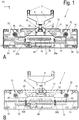
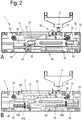
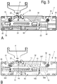
- the Figures 1 to 3 reproduce the feed device in different positions, hidden lines not being visible in the respective FIG. A, whereas hidden lines are partially visible as dashed lines in the associated FIG.
- the Figures 4 and 5 correspond to the view in the position of the Fig. 1A , where in the Figures 4 and 5 various elements of the feed device are not used in order to be able to better recognize the elements underneath. In this sense, the Figures 4 and 5 the retraction device in intermediate steps of its assembly. In addition, an upper housing cover of the retraction device is omitted in all figures, in order to be able to gain insight into its structure.
- top, bottom, left, right, front, rear, etc. refer exclusively to the exemplary representation selected in the figures. These terms are not to be understood as restrictive and should be interpreted in the context of the respective figure.
- a pull-in device 1 is shown in interaction with a door fitting 2 (cf. Fig. 1 ).
- the feed device 1 is also referred to as device 1 in the following.
- the door fitting 2 is direct or indirect fixed to a movable sliding door, not shown here, for example in the fastening dowel 3 in corresponding bores of the sliding door or the running part of the sliding door.
- the door fitting 2 has a pin-like activator 4 at its lower end, which interacts with the pull-in device 1.
- the sliding door is mounted to be movable to the right and left. Corresponding guide rails for the sliding door are also not shown here.
- the sliding direction of the sliding door is also referred to below as the x direction, a movement to the right meaning a movement to positive x values and a movement to the left meaning a movement to negative x values.
- the device 1 is mounted directly or indirectly in a stationary manner, for example on a furniture body, a guide rail arranged on the body side or an end stop arranged on the body side.
- an activator can also be arranged in a stationary manner on the furniture body and the device 1 can be attached to the sliding door so that it moves laterally with it. In this way, the same functionality is achieved as in the device 1 assumed to be stationary in the example shown here.
- the device 1 has a housing 10, of which only one lower housing shell is shown in the present case. Like an upper housing shell (not shown), this is preferably produced in one piece, for example in a plastic injection molding process. For reinforcement, 10 webs 17 (cf. Fig. 4 ) be arranged, which also serve to protect against dust and sight.
- the device 1 has a driver 20 which partially protrudes from the housing 10 and with which the activator 4 of the door fitting 2 interacts.
- the driver has a middle piece 21 and lateral claws 22, 23 hinged to this middle piece 21.
- a straight guide path 11 is formed in the housing 10, along which the middle piece 21 and thus the driver 20 can move laterally. In the case shown, the middle piece 21 engages with two guide pins in the straight guide track 11.
- the guide pins also simultaneously form an axis of rotation for the articulated claws 22, 23. At a distance from the articulation points, a further guide pin is inserted into each of the claws 22, 23, which cooperates with a guide track 12 of the housing 10 that is angled at its ends and straight in the central region .
- the driver 20 can also be designed differently than shown in the figures.
- the guide pins can be designed in a different shape, number and / or position on the driver 20.
- the claws 22 and 23 enclose in the in the Figure 1 shown center position the activator 4 of the Door fittings. When the driver 20 moves laterally, the shape of the mouth formed in this way and enclosing the activator 4 does not initially change.
- the device 1 has three slides which are also guided laterally, a center slide 30, a left side slide 40 and a right side slide 50.
- a straight slideway 13 is embodied in the housing 10.
- a central housing dome 14 is also used for guidance purposes and also serves to accommodate screws for connecting the housing halves of the housing 10.
- the slides 30, 40, 50 are arranged in different parallel planes to one another.
- the side slides 40, 50 lie directly on the lower housing shell and are guided in the slide guide path 13.
- the side slides 40, 50 are thus arranged within a first level. This is good in Fig. 4 to see, which shows a view of the device 1 with the center slide 30 removed.
- the middle slide 30 is arranged partially overlapping on the side slide 40, 50 in a second plane.
- the center slide 30 is guided with a guide slot 31 through the housing dome 14 and with contours 32 on correspondingly designed contours 41, 51 of the side slides 40 and 50, respectively.
- a further guidance of the slides 30, 40, 50 in the lateral direction can be achieved by appropriate guideways of the upper one Housing shell take place.
- the lateral movement of the center slide 30 is coupled to that of the catch 20 by means of a left or right locking slot 33 or 34, which are arranged in the upper part of the center slide 30 in the figures and on whose outer side walls the guide pins of the catch 20 rest .
- the driver 20 and the center slide 30 remain in the position shown in FIG 2A, 2B and 3A, 3B shown left or right opening position. It is only when the open claw 22 or 23 is raised again along the angled guideway 12 and the mouth of the catch 20 is closed when the activator 4 moves back, that the catch 20 and the center slide 30 on the housing 10 are also released.
- the side slides 40, 50 have control slide guide slots 42 and 52, which run perpendicular to the lateral displacement direction x and in which a control slide 400 and 500 can move back and forth in the y direction (cf. in particular Fig. 4 ).
- the control slides 400, 500 serve to couple the center slide 30 to the left side slide 40 and the right side slide 50.
- the control slides 400, 500 each have a coupling pin 401 or protruding from the image plane of the figures in the direction of the center slide 30. 501 on.
- these coupling pins 401, 501 interact with a respective coupling slot 35 and 36, respectively, in the left and right area of the center spool 30.
- control spools 400, 500 furthermore has a guide pin 402 or 502 facing the lower housing shell of the housing 10. This is in each case guided in a left or right control track 15, 16 embodied in the housing 10.
- the control tracks 15, 16 are each angled in their section pointing towards the center of the device 1. In this way, on the one hand, the lateral movement of the side slides 40, 50 towards the center is limited.
- the respective control slide 400, 500 is pushed downward, ie away from the driver 20 in the negative y direction, when the respective side slide 40, 50 is in its inner stop position, ie on the left stop on the right side slide 50 or on the right Stop at the left sideshift 40.
- the left side slide 40 is thus fixed at its right, inner stop position on the housing 10 by a control slide 400 pushed down in the negative y-direction and decoupled from the center slide 30.
- Moving the control spool 400 in the angled area of the Control path 15 is supported by an inclined upper portion 37b of the locking slot 35.
- the right-hand side slide 50 is coupled to the center slide 30 by a right control slide 500 which is pushed up into the coupling slot 36 in the positive y direction and moves to the right with this, as in FIG Fig. 2 evident.
- the insertion of the control slide 500 into the locking slot 36 is supported by an obliquely running lower section 38a of the locking slot 36.
- the mouth of the driver 20 then opens by moving the right claw 23 when the corresponding guide pin is immersed in the angled region of the guide track 12.
- the right side slide 50 is fixed at its left stop position and decoupled from the center slide 30, whereas the left side slide 40 is moved to the left by a control slide 400 pushed up to the center slide 30 until the left claw 22 is guided through the angled guideway 12 opens the mouth of the driver 20 and at the same time fixes the driver 20 and thus the center slide 30 and the left side slide 40 in the left end position shown.
- the displacement of the control slide 500 into the angled region of the control track 16 is supported by an obliquely running upper section 38b of the locking slot 36.
- the insertion of the control slide 400 into the locking slot 35 is supported by an obliquely running lower section 37a of the locking slot 35.
- the side slides 40, 50 are therefore at a minimum distance from one another when the driver 20 and thus the sliding door are in the middle position (cf. Fig. 1 , 4th ).
- the distance between the two side slides 40 and 50 increases, regardless of which of the opening directions this movement takes place.
- the side slides 40, 50 are now coupled to one another on the one hand via a damping device 60 and on the other hand via a mechanical energy storage arrangement 70.
- the side slides 40, 50 have receptacles 43 and 53 in their respective inner areas for receiving the ends of the damping device 60.
- the damping device 60 has at least one cylinder 62 and a piston rod 61 (cf. Fig.
- one of the receptacles here, for example, the receptacle 43 of the left side slide 40 is designed to engage with a head of the piston rod 61 and the other of the receptacles, here, for example, the receptacle 53 of the right side slide 50, is designed for the cylinder 62 to connect the damping device 60 to the corresponding side slide 50.
- the damping device 60 is designed in a known manner in such a way that the piston rod 61 can be pulled out of the cylinder 62 with as little force as possible, whereas the piston rod 61 is pressed into the cylinder 62 in a damped manner.
- the side slides 40, 50 are connected to one another via the energy storage arrangement 70.
- a spring connected directly to the side slides 40, 50 could be used as the energy storage arrangement 70.
- the spring pulls the two side carriages 40, 50 towards one another, in particular the laterally displaced side carriages 40, 50 towards the other fixed side carriages 50, 40, and is consequently tensioned or further tensioned with respect to a generally existing bias when the sliding door is off the middle position is moved to one of the two sides. Due to the above-described locking of driver 20, center slide 30 and (depending on the direction of movement) one of the two side slides 40, 50, the spring remains in the tensioned state until the activator 4 releases this locking mechanism when the door moves back. As a result, the spring force automatically pulls the door back into the middle position.
- the energy storage arrangement 70 is not a spring connected directly to the side parts 40, 50, but rather a spring 71 which is arranged in the central region of the device 1 and which interacts with a winding device 72, 74 in each case by means of ropes acting at its ends .
- the winding devices 72, 74 each comprise a gear wheel which engages in a toothed rack 44 or 54 of the left or right side slide 40, 50.
- each of the winding devices 72, 74 has a winding curve 73, 75, which is approximately spiral-shaped.
- the spring 71 is pulled apart as an energy store when the side slides 40, 50 move away from one another.
- the spring practices 71 a restoring force on the respective laterally laterally displaced side slides 40, 50 in the direction of the central position.
- the winding devices 72 and 74 enable the force / travel relationship between the distance of the side slides 40, 50 from one another and the restoring force acting on them to be influenced by appropriately designing the winding curves 73 and 75.
- the feed device is in a central position ( Figure 6A ), in the right open position ( Figure 6B ) and in the left open position ( Figure 6C ).
- the drawing-in device 1 of the second exemplary embodiment does not differ from that in FIGS Figures 1 to 5 shown feeder of the first embodiment. Reference is hereby made to the associated description of the first exemplary embodiment.
- the carrier 20 is formed in two parts by two claws 22, 23.
- a center piece 21, as used in the first embodiment, is not used in this embodiment.
- the control slides 400, 500, which fix the left side slide 40 and the right side slide 50 in the respective open position of the driver 20, are designed as swivel levers.
- the pull-in device 1 automatically moves a movable furniture part, in particular a sliding door, into a central position, a single energy storage arrangement 70 and a single damping device 60 being used.
- Both the energy storage arrangement 70 and the damping device 60 are effective when the door is moved in both directions or when the door is moved back from both directions.
- the fact that two cylinders 62 are used in the exemplary embodiments described occurs in order to enable a desired damping behavior with a flat construction of the device 1. Both cylinders 62 work in parallel, so that in principle they could also be replaced by a larger one. If the damping device were only effective in one direction of movement, it would be necessary to achieve the desired one Damping behavior four of the shown or two larger cylinders are used.
- the pull-in device 1 according to the invention also offers the essential advantage over the prior art that the pull-in effect and possibly the damping effect is the same in both directions, while when using the previously known separate pull-in devices, for example due to manufacturing tolerances, the pull-in and damping effect and thus also the movement of the movable furniture part can vary depending on the direction.
Landscapes
- Power-Operated Mechanisms For Wings (AREA)
- Support Devices For Sliding Doors (AREA)
- Drawers Of Furniture (AREA)
- Closing And Opening Devices For Wings, And Checks For Wings (AREA)
- Cabinets, Racks, Or The Like Of Rigid Construction (AREA)
Priority Applications (1)
| Application Number | Priority Date | Filing Date | Title |
|---|---|---|---|
| PL12743451T PL2744963T3 (pl) | 2011-08-16 | 2012-08-02 | Mechanizm do dociągania ruchomej części mebla do ustawienia środkowego |
Applications Claiming Priority (2)
| Application Number | Priority Date | Filing Date | Title |
|---|---|---|---|
| DE102011052756.7A DE102011052756B4 (de) | 2011-08-16 | 2011-08-16 | Vorrichtung zum Einziehen eines bewegbaren Möbelteils in eine Mittelstellung |
| PCT/EP2012/065185 WO2013023934A1 (de) | 2011-08-16 | 2012-08-02 | Vorrichtung zum einziehen eines bewegbaren möbelteils in eine mittelstellung |
Publications (2)
| Publication Number | Publication Date |
|---|---|
| EP2744963A1 EP2744963A1 (de) | 2014-06-25 |
| EP2744963B1 true EP2744963B1 (de) | 2020-06-10 |
Family
ID=46614486
Family Applications (1)
| Application Number | Title | Priority Date | Filing Date |
|---|---|---|---|
| EP12743451.2A Active EP2744963B1 (de) | 2011-08-16 | 2012-08-02 | Vorrichtung zum einziehen eines bewegbaren möbelteils in eine mittelstellung |
Country Status (11)
| Country | Link |
|---|---|
| EP (1) | EP2744963B1 (enExample) |
| JP (1) | JP2014527438A (enExample) |
| KR (1) | KR101948752B1 (enExample) |
| CN (1) | CN103764933B (enExample) |
| BR (1) | BR112014003517A2 (enExample) |
| DE (1) | DE102011052756B4 (enExample) |
| ES (1) | ES2808679T3 (enExample) |
| PL (1) | PL2744963T3 (enExample) |
| RU (1) | RU2597818C2 (enExample) |
| TW (1) | TW201311989A (enExample) |
| WO (1) | WO2013023934A1 (enExample) |
Families Citing this family (3)
| Publication number | Priority date | Publication date | Assignee | Title |
|---|---|---|---|---|
| KR200483362Y1 (ko) * | 2016-05-10 | 2017-05-24 | 유상현 | 가구용 미닫이 도어의 댐핑장치 |
| DE102016007885A1 (de) * | 2016-06-29 | 2018-01-04 | Günther Zimmer | Mitteltür-Zuziehvorrichtung mit Übertragungsschlitten |
| DE102019132208A1 (de) | 2019-11-27 | 2021-05-27 | Paul Hettich Gmbh & Co. Kg | Möbelelement |
Family Cites Families (10)
| Publication number | Priority date | Publication date | Assignee | Title |
|---|---|---|---|---|
| SU1722442A1 (ru) * | 1989-12-29 | 1992-03-30 | А.В.Загорулькин | Подъемник дл перемещени секций корпусной мебели |
| JP3930459B2 (ja) * | 2003-06-30 | 2007-06-13 | 株式会社シモダイラ | 引戸の戸閉装置 |
| CN101305150B (zh) * | 2005-11-08 | 2012-02-29 | 株式会社利富高 | 引入机构 |
| DE102008009046B4 (de) | 2008-02-13 | 2014-10-02 | Günther Zimmer | Beschleunigungs- und Verzögerungsvorrichtung mit zwei Mitnahmeelementen |
| JP4813523B2 (ja) | 2008-07-22 | 2011-11-09 | 株式会社シモダイラ | 戸閉装置 |
| DE202009016834U1 (de) * | 2009-12-14 | 2010-04-22 | Krischke-Lengersdorf, Christian | Einrichtung zum Dämpfen der Relativbewegung bewegter Vorrichtungsteile, insbesondere von Schiebetüren |
| DE202010000143U1 (de) * | 2010-02-08 | 2011-06-09 | Karl Simon GmbH & Co. KG, 78733 | Einzugvorrichtung für Schiebetüren |
| DE202010007230U1 (de) | 2010-05-27 | 2010-08-26 | Häfele GmbH & Co. KG | Bidirektionale Einzugsvorrichtung für eine mittlere Schiebetür |
| EP2538010B1 (de) * | 2011-06-22 | 2014-10-08 | Krischke-Lengersdorf, Christian | Positionsrückführvorrichtung, insbesondere für Schiebetüren |
| DE202012104360U1 (de) * | 2012-11-13 | 2012-11-21 | Häfele GmbH & Co. KG | Bidirektionale Einzugsvorrichtung für eine mittlere Schiebetür |
-
2011
- 2011-08-16 DE DE102011052756.7A patent/DE102011052756B4/de active Active
-
2012
- 2012-08-02 ES ES12743451T patent/ES2808679T3/es active Active
- 2012-08-02 RU RU2014108963/12A patent/RU2597818C2/ru active
- 2012-08-02 KR KR1020147006974A patent/KR101948752B1/ko not_active Expired - Fee Related
- 2012-08-02 WO PCT/EP2012/065185 patent/WO2013023934A1/de not_active Ceased
- 2012-08-02 BR BR112014003517A patent/BR112014003517A2/pt not_active IP Right Cessation
- 2012-08-02 JP JP2014525393A patent/JP2014527438A/ja not_active Ceased
- 2012-08-02 CN CN201280040158.0A patent/CN103764933B/zh active Active
- 2012-08-02 EP EP12743451.2A patent/EP2744963B1/de active Active
- 2012-08-02 PL PL12743451T patent/PL2744963T3/pl unknown
- 2012-08-07 TW TW101128358A patent/TW201311989A/zh unknown
Non-Patent Citations (1)
| Title |
|---|
| None * |
Also Published As
| Publication number | Publication date |
|---|---|
| KR20140064875A (ko) | 2014-05-28 |
| CN103764933B (zh) | 2016-01-13 |
| BR112014003517A2 (pt) | 2017-03-14 |
| RU2597818C2 (ru) | 2016-09-20 |
| ES2808679T3 (es) | 2021-03-01 |
| TW201311989A (zh) | 2013-03-16 |
| KR101948752B1 (ko) | 2019-02-15 |
| WO2013023934A1 (de) | 2013-02-21 |
| JP2014527438A (ja) | 2014-10-16 |
| CN103764933A (zh) | 2014-04-30 |
| DE102011052756A1 (de) | 2013-02-21 |
| EP2744963A1 (de) | 2014-06-25 |
| RU2014108963A (ru) | 2015-09-27 |
| DE102011052756B4 (de) | 2024-06-13 |
| PL2744963T3 (pl) | 2020-11-16 |
Similar Documents
| Publication | Publication Date | Title |
|---|---|---|
| EP3244775B1 (de) | Möbelantrieb | |
| EP2001327B1 (de) | Antriebsmechanismus für ein in oder an einem möbel bewegbar gelagertes möbelteil | |
| EP2373195B1 (de) | Selbsteinzugsvorrichtung und auszugsführung | |
| EP3484327B1 (de) | Antriebsvorrichtung für ein bewegbares möbelteil und verfahren zum öffnen und schliessen eines bewegbaren möbelteils | |
| AT521139B1 (de) | Führungssystem zur Führung eines bewegbar gelagerten Türflügels | |
| EP3141153B1 (de) | Vorrichtung zum bewegen eines bewegbaren möbelteils in eine öffnungsrichtung in bezug zu einem möbelkorpus eines möbels | |
| WO2014165873A1 (de) | Antriebsvorrichtung für ein bewegbares möbelteil | |
| EP3341545B1 (de) | Vorrichtung zum positionieren von zwei schiebetüren und möbel | |
| EP1500763B1 (de) | Ausziehsperreinrichtung für mindestens zwei wechselweise aus einem Möbelkorpus ausziehbare Schubladen | |
| EP4077844B1 (de) | Anordnung zur führung einer schiebetür oder falt-schiebetür | |
| EP3376899B1 (de) | Einzugsvorrichtung für bewegbare möbelteile | |
| WO2018059987A1 (de) | Einzugsvorrichtung für einen schubladenauszug | |
| EP3133232A1 (de) | Vorrichtung zum bewegen eines bewegbaren möbelteils sowie möbel mit einer vorrichtung zum bewegen eines bewegbaren möbelteils | |
| AT514666B1 (de) | Führungsvorrichtung für bewegbare Möbelteile | |
| EP2744963B1 (de) | Vorrichtung zum einziehen eines bewegbaren möbelteils in eine mittelstellung | |
| EP2630320B1 (de) | Schubladenbeschlag zum anbinden einer schublade an einen zentralverschluss | |
| EP3142516A1 (de) | Einzugsvorrichtung für möbel | |
| EP3675691B1 (de) | Einzugsvorrichtung zum einziehen eines bewegbaren teils eines möbels oder haushaltsgeräts in eine endlage | |
| DE20318929U1 (de) | Einzugsautomatik für Schubladen-Ausziehführungen | |
| EP4217562B1 (de) | Ausziehsperrvorrichtung für schubladen | |
| EP2848759B1 (de) | Dämpfungsvorrichtung | |
| EP3293055B1 (de) | Schliesseinrichtung für ein fach |
Legal Events
| Date | Code | Title | Description |
|---|---|---|---|
| PUAI | Public reference made under article 153(3) epc to a published international application that has entered the european phase |
Free format text: ORIGINAL CODE: 0009012 |
|
| 17P | Request for examination filed |
Effective date: 20140307 |
|
| AK | Designated contracting states |
Kind code of ref document: A1 Designated state(s): AL AT BE BG CH CY CZ DE DK EE ES FI FR GB GR HR HU IE IS IT LI LT LU LV MC MK MT NL NO PL PT RO RS SE SI SK SM TR |
|
| DAX | Request for extension of the european patent (deleted) | ||
| RAP1 | Party data changed (applicant data changed or rights of an application transferred) |
Owner name: HETTICH-HEINZE GMBH & CO. KG |
|
| STAA | Information on the status of an ep patent application or granted ep patent |
Free format text: STATUS: EXAMINATION IS IN PROGRESS |
|
| 17Q | First examination report despatched |
Effective date: 20170410 |
|
| GRAP | Despatch of communication of intention to grant a patent |
Free format text: ORIGINAL CODE: EPIDOSNIGR1 |
|
| STAA | Information on the status of an ep patent application or granted ep patent |
Free format text: STATUS: GRANT OF PATENT IS INTENDED |
|
| INTG | Intention to grant announced |
Effective date: 20191126 |
|
| GRAS | Grant fee paid |
Free format text: ORIGINAL CODE: EPIDOSNIGR3 |
|
| GRAJ | Information related to disapproval of communication of intention to grant by the applicant or resumption of examination proceedings by the epo deleted |
Free format text: ORIGINAL CODE: EPIDOSDIGR1 |
|
| GRAL | Information related to payment of fee for publishing/printing deleted |
Free format text: ORIGINAL CODE: EPIDOSDIGR3 |
|
| STAA | Information on the status of an ep patent application or granted ep patent |
Free format text: STATUS: EXAMINATION IS IN PROGRESS |
|
| GRAP | Despatch of communication of intention to grant a patent |
Free format text: ORIGINAL CODE: EPIDOSNIGR1 |
|
| STAA | Information on the status of an ep patent application or granted ep patent |
Free format text: STATUS: GRANT OF PATENT IS INTENDED |
|
| INTC | Intention to grant announced (deleted) | ||
| GRAS | Grant fee paid |
Free format text: ORIGINAL CODE: EPIDOSNIGR3 |
|
| GRAA | (expected) grant |
Free format text: ORIGINAL CODE: 0009210 |
|
| STAA | Information on the status of an ep patent application or granted ep patent |
Free format text: STATUS: THE PATENT HAS BEEN GRANTED |
|
| INTG | Intention to grant announced |
Effective date: 20200420 |
|
| AK | Designated contracting states |
Kind code of ref document: B1 Designated state(s): AL AT BE BG CH CY CZ DE DK EE ES FI FR GB GR HR HU IE IS IT LI LT LU LV MC MK MT NL NO PL PT RO RS SE SI SK SM TR |
|
| REG | Reference to a national code |
Ref country code: GB Ref legal event code: FG4D Free format text: NOT ENGLISH |
|
| REG | Reference to a national code |
Ref country code: CH Ref legal event code: EP Ref country code: AT Ref legal event code: REF Ref document number: 1279327 Country of ref document: AT Kind code of ref document: T Effective date: 20200615 |
|
| REG | Reference to a national code |
Ref country code: DE Ref legal event code: R096 Ref document number: 502012016132 Country of ref document: DE |
|
| REG | Reference to a national code |
Ref country code: IE Ref legal event code: FG4D Free format text: LANGUAGE OF EP DOCUMENT: GERMAN |
|
| REG | Reference to a national code |
Ref country code: CH Ref legal event code: NV Representative=s name: ISLER AND PEDRAZZINI AG, CH |
|
| REG | Reference to a national code |
Ref country code: LT Ref legal event code: MG4D |
|
| PG25 | Lapsed in a contracting state [announced via postgrant information from national office to epo] |
Ref country code: NO Free format text: LAPSE BECAUSE OF FAILURE TO SUBMIT A TRANSLATION OF THE DESCRIPTION OR TO PAY THE FEE WITHIN THE PRESCRIBED TIME-LIMIT Effective date: 20200910 Ref country code: GR Free format text: LAPSE BECAUSE OF FAILURE TO SUBMIT A TRANSLATION OF THE DESCRIPTION OR TO PAY THE FEE WITHIN THE PRESCRIBED TIME-LIMIT Effective date: 20200911 Ref country code: LT Free format text: LAPSE BECAUSE OF FAILURE TO SUBMIT A TRANSLATION OF THE DESCRIPTION OR TO PAY THE FEE WITHIN THE PRESCRIBED TIME-LIMIT Effective date: 20200610 Ref country code: SE Free format text: LAPSE BECAUSE OF FAILURE TO SUBMIT A TRANSLATION OF THE DESCRIPTION OR TO PAY THE FEE WITHIN THE PRESCRIBED TIME-LIMIT Effective date: 20200610 Ref country code: FI Free format text: LAPSE BECAUSE OF FAILURE TO SUBMIT A TRANSLATION OF THE DESCRIPTION OR TO PAY THE FEE WITHIN THE PRESCRIBED TIME-LIMIT Effective date: 20200610 |
|
| REG | Reference to a national code |
Ref country code: DE Ref legal event code: R084 Ref document number: 502012016132 Country of ref document: DE |
|
| REG | Reference to a national code |
Ref country code: NL Ref legal event code: MP Effective date: 20200610 |
|
| PG25 | Lapsed in a contracting state [announced via postgrant information from national office to epo] |
Ref country code: BG Free format text: LAPSE BECAUSE OF FAILURE TO SUBMIT A TRANSLATION OF THE DESCRIPTION OR TO PAY THE FEE WITHIN THE PRESCRIBED TIME-LIMIT Effective date: 20200910 Ref country code: HR Free format text: LAPSE BECAUSE OF FAILURE TO SUBMIT A TRANSLATION OF THE DESCRIPTION OR TO PAY THE FEE WITHIN THE PRESCRIBED TIME-LIMIT Effective date: 20200610 Ref country code: LV Free format text: LAPSE BECAUSE OF FAILURE TO SUBMIT A TRANSLATION OF THE DESCRIPTION OR TO PAY THE FEE WITHIN THE PRESCRIBED TIME-LIMIT Effective date: 20200610 Ref country code: RS Free format text: LAPSE BECAUSE OF FAILURE TO SUBMIT A TRANSLATION OF THE DESCRIPTION OR TO PAY THE FEE WITHIN THE PRESCRIBED TIME-LIMIT Effective date: 20200610 |
|
| PG25 | Lapsed in a contracting state [announced via postgrant information from national office to epo] |
Ref country code: AL Free format text: LAPSE BECAUSE OF FAILURE TO SUBMIT A TRANSLATION OF THE DESCRIPTION OR TO PAY THE FEE WITHIN THE PRESCRIBED TIME-LIMIT Effective date: 20200610 Ref country code: NL Free format text: LAPSE BECAUSE OF FAILURE TO SUBMIT A TRANSLATION OF THE DESCRIPTION OR TO PAY THE FEE WITHIN THE PRESCRIBED TIME-LIMIT Effective date: 20200610 |
|
| PG25 | Lapsed in a contracting state [announced via postgrant information from national office to epo] |
Ref country code: PT Free format text: LAPSE BECAUSE OF FAILURE TO SUBMIT A TRANSLATION OF THE DESCRIPTION OR TO PAY THE FEE WITHIN THE PRESCRIBED TIME-LIMIT Effective date: 20201012 Ref country code: CZ Free format text: LAPSE BECAUSE OF FAILURE TO SUBMIT A TRANSLATION OF THE DESCRIPTION OR TO PAY THE FEE WITHIN THE PRESCRIBED TIME-LIMIT Effective date: 20200610 Ref country code: RO Free format text: LAPSE BECAUSE OF FAILURE TO SUBMIT A TRANSLATION OF THE DESCRIPTION OR TO PAY THE FEE WITHIN THE PRESCRIBED TIME-LIMIT Effective date: 20200610 Ref country code: EE Free format text: LAPSE BECAUSE OF FAILURE TO SUBMIT A TRANSLATION OF THE DESCRIPTION OR TO PAY THE FEE WITHIN THE PRESCRIBED TIME-LIMIT Effective date: 20200610 Ref country code: SM Free format text: LAPSE BECAUSE OF FAILURE TO SUBMIT A TRANSLATION OF THE DESCRIPTION OR TO PAY THE FEE WITHIN THE PRESCRIBED TIME-LIMIT Effective date: 20200610 |
|
| PG25 | Lapsed in a contracting state [announced via postgrant information from national office to epo] |
Ref country code: SK Free format text: LAPSE BECAUSE OF FAILURE TO SUBMIT A TRANSLATION OF THE DESCRIPTION OR TO PAY THE FEE WITHIN THE PRESCRIBED TIME-LIMIT Effective date: 20200610 Ref country code: IS Free format text: LAPSE BECAUSE OF FAILURE TO SUBMIT A TRANSLATION OF THE DESCRIPTION OR TO PAY THE FEE WITHIN THE PRESCRIBED TIME-LIMIT Effective date: 20201010 |
|
| REG | Reference to a national code |
Ref country code: ES Ref legal event code: FG2A Ref document number: 2808679 Country of ref document: ES Kind code of ref document: T3 Effective date: 20210301 |
|
| REG | Reference to a national code |
Ref country code: DE Ref legal event code: R097 Ref document number: 502012016132 Country of ref document: DE |
|
| PG25 | Lapsed in a contracting state [announced via postgrant information from national office to epo] |
Ref country code: MC Free format text: LAPSE BECAUSE OF FAILURE TO SUBMIT A TRANSLATION OF THE DESCRIPTION OR TO PAY THE FEE WITHIN THE PRESCRIBED TIME-LIMIT Effective date: 20200610 |
|
| PLBE | No opposition filed within time limit |
Free format text: ORIGINAL CODE: 0009261 |
|
| STAA | Information on the status of an ep patent application or granted ep patent |
Free format text: STATUS: NO OPPOSITION FILED WITHIN TIME LIMIT |
|
| PG25 | Lapsed in a contracting state [announced via postgrant information from national office to epo] |
Ref country code: LU Free format text: LAPSE BECAUSE OF NON-PAYMENT OF DUE FEES Effective date: 20200802 Ref country code: DK Free format text: LAPSE BECAUSE OF FAILURE TO SUBMIT A TRANSLATION OF THE DESCRIPTION OR TO PAY THE FEE WITHIN THE PRESCRIBED TIME-LIMIT Effective date: 20200610 |
|
| REG | Reference to a national code |
Ref country code: ES Ref legal event code: GC2A Effective date: 20210427 |
|
| 26N | No opposition filed |
Effective date: 20210311 |
|
| GBPC | Gb: european patent ceased through non-payment of renewal fee |
Effective date: 20200910 |
|
| REG | Reference to a national code |
Ref country code: BE Ref legal event code: MM Effective date: 20200831 |
|
| PG25 | Lapsed in a contracting state [announced via postgrant information from national office to epo] |
Ref country code: SI Free format text: LAPSE BECAUSE OF FAILURE TO SUBMIT A TRANSLATION OF THE DESCRIPTION OR TO PAY THE FEE WITHIN THE PRESCRIBED TIME-LIMIT Effective date: 20200610 |
|
| PG25 | Lapsed in a contracting state [announced via postgrant information from national office to epo] |
Ref country code: FR Free format text: LAPSE BECAUSE OF NON-PAYMENT OF DUE FEES Effective date: 20200810 |
|
| PG25 | Lapsed in a contracting state [announced via postgrant information from national office to epo] |
Ref country code: BE Free format text: LAPSE BECAUSE OF NON-PAYMENT OF DUE FEES Effective date: 20200831 Ref country code: IE Free format text: LAPSE BECAUSE OF NON-PAYMENT OF DUE FEES Effective date: 20200802 Ref country code: GB Free format text: LAPSE BECAUSE OF NON-PAYMENT OF DUE FEES Effective date: 20200910 |
|
| REG | Reference to a national code |
Ref country code: AT Ref legal event code: MM01 Ref document number: 1279327 Country of ref document: AT Kind code of ref document: T Effective date: 20200802 |
|
| PG25 | Lapsed in a contracting state [announced via postgrant information from national office to epo] |
Ref country code: AT Free format text: LAPSE BECAUSE OF NON-PAYMENT OF DUE FEES Effective date: 20200802 |
|
| PG25 | Lapsed in a contracting state [announced via postgrant information from national office to epo] |
Ref country code: MT Free format text: LAPSE BECAUSE OF FAILURE TO SUBMIT A TRANSLATION OF THE DESCRIPTION OR TO PAY THE FEE WITHIN THE PRESCRIBED TIME-LIMIT Effective date: 20200610 Ref country code: CY Free format text: LAPSE BECAUSE OF FAILURE TO SUBMIT A TRANSLATION OF THE DESCRIPTION OR TO PAY THE FEE WITHIN THE PRESCRIBED TIME-LIMIT Effective date: 20200610 |
|
| PG25 | Lapsed in a contracting state [announced via postgrant information from national office to epo] |
Ref country code: MK Free format text: LAPSE BECAUSE OF FAILURE TO SUBMIT A TRANSLATION OF THE DESCRIPTION OR TO PAY THE FEE WITHIN THE PRESCRIBED TIME-LIMIT Effective date: 20200610 |
|
| P01 | Opt-out of the competence of the unified patent court (upc) registered |
Effective date: 20230407 |
|
| PGFP | Annual fee paid to national office [announced via postgrant information from national office to epo] |
Ref country code: DE Payment date: 20240819 Year of fee payment: 13 |
|
| PGFP | Annual fee paid to national office [announced via postgrant information from national office to epo] |
Ref country code: CH Payment date: 20240901 Year of fee payment: 13 Ref country code: ES Payment date: 20240918 Year of fee payment: 13 |
|
| PGFP | Annual fee paid to national office [announced via postgrant information from national office to epo] |
Ref country code: PL Payment date: 20240722 Year of fee payment: 13 |
|
| PGFP | Annual fee paid to national office [announced via postgrant information from national office to epo] |
Ref country code: IT Payment date: 20240830 Year of fee payment: 13 |
|
| PGFP | Annual fee paid to national office [announced via postgrant information from national office to epo] |
Ref country code: TR Payment date: 20240723 Year of fee payment: 13 |