EP2744741B1 - Mobilteil - Google Patents
Mobilteil Download PDFInfo
- Publication number
- EP2744741B1 EP2744741B1 EP12738032.7A EP12738032A EP2744741B1 EP 2744741 B1 EP2744741 B1 EP 2744741B1 EP 12738032 A EP12738032 A EP 12738032A EP 2744741 B1 EP2744741 B1 EP 2744741B1
- Authority
- EP
- European Patent Office
- Prior art keywords
- electronic unit
- mobile part
- unit
- rollers
- part according
- Prior art date
- Legal status (The legal status is an assumption and is not a legal conclusion. Google has not performed a legal analysis and makes no representation as to the accuracy of the status listed.)
- Active
Links
Images



Classifications
-
- B—PERFORMING OPERATIONS; TRANSPORTING
- B66—HOISTING; LIFTING; HAULING
- B66F—HOISTING, LIFTING, HAULING OR PUSHING, NOT OTHERWISE PROVIDED FOR, e.g. DEVICES WHICH APPLY A LIFTING OR PUSHING FORCE DIRECTLY TO THE SURFACE OF A LOAD
- B66F9/00—Devices for lifting or lowering bulky or heavy goods for loading or unloading purposes
- B66F9/06—Devices for lifting or lowering bulky or heavy goods for loading or unloading purposes movable, with their loads, on wheels or the like, e.g. fork-lift trucks
- B66F9/063—Automatically guided
-
- B—PERFORMING OPERATIONS; TRANSPORTING
- B62—LAND VEHICLES FOR TRAVELLING OTHERWISE THAN ON RAILS
- B62D—MOTOR VEHICLES; TRAILERS
- B62D1/00—Steering controls, i.e. means for initiating a change of direction of the vehicle
- B62D1/24—Steering controls, i.e. means for initiating a change of direction of the vehicle not vehicle-mounted
- B62D1/28—Steering controls, i.e. means for initiating a change of direction of the vehicle not vehicle-mounted non-mechanical, e.g. following a line or other known markers
- B62D1/283—Steering controls, i.e. means for initiating a change of direction of the vehicle not vehicle-mounted non-mechanical, e.g. following a line or other known markers for unmanned vehicles
Definitions
- the invention relates to a handset.
- the invention is therefore the object of developing a handset, a simple handling should be achievable, in particular maintenance of the drive or electronics should be easy to perform.
- the mobile part has an electronics unit and a receiving unit, in particular receiving plate, wherein the electronic unit has an electric drive, in particular comprising an electric motor, and drive rollers which can be driven by the electric drive for moving the mobile part along a travel surface, in particular thus a travel plane section, in which the receiving unit by means of rollers, in particular castors, supported and / or is movable for moving the receiving part along the traversing surface, in particular so the ground, in particular in different directions, wherein the electronic unit is rotatably mounted on the receiving unit, in particular wherein the axis of rotation perpendicular to the travel surface.
- an electric drive in particular comprising an electric motor
- drive rollers which can be driven by the electric drive for moving the mobile part along a travel surface, in particular thus a travel plane section, in which the receiving unit by means of rollers, in particular castors, supported and / or is movable for moving the receiving part along the traversing surface, in particular so the ground, in particular in different directions, wherein the electronic unit is rotatably
- the advantage here is that the receiving unit is supported and held by rollers on the travel surface. Thus, no weight of the receiving unit via the electronic unit to derive the traversing surface.
- the electronics unit itself has drive rollers, so that their weight can be conducted to them via the latter to the traveling surface. Thus, the maintenance of the electronics unit is easy to carry out, since the recording unit does not need to be affected. A simple decoupling of the two units is sufficient.
- the electronic unit on auxiliary rollers with which it is movable along the travel surface after lifting the drive rollers by means arranged on the electronic unit lifting device, in particular service claw, for lifting the drive rollers (7).
- the advantage here is that easy maintenance is achievable.
- the drive rollers When deactivating, in particular lifting the drive rollers away from the travel surface, the drive rollers have auxiliary rollers which divert the weight.
- the rotatable mounting of the electronics unit is carried out on the receiving part by means of a sliding bearing.
- a sliding bearing is used and axial forces are absorbed by the bearing.
- slots for fastening a load and / or a conveying device, in particular a runway, for a load with electrically driven and / or non-driven rollers, or a lifting fork, a lifting table or another handling system are arranged on the receiving unit, in particular, wherein the electrical supply of the conveyor device is performed by the electronic unit.
- the housing of the electronics unit has a lower part, in particular trough-like shaped lower part, and an upper part, in particular a housing cover, mounted thereon, in particular, wherein the sliding bearing between the receiving plate and the lower part is arranged.
- the lifting device for lifting the drive rollers is designed such that the lower part of the electronics unit when lifting the rollers, the lower part is approaching the Verfahr configuration such that the auxiliary rollers touch the traversing surface.
- the advantage here is that the separation of the electronics unit from the receiving unit in is simple manner by decoupling the units in the region of the plain bearing. This is preferably achieved by a lifting device which raises the drive rollers and thereby presses out an axle section protruding from the electronics unit from a recess in the receiving unit acting as a receiving bore.
- the drive roller and / or the associated drive of the remaining electronics unit is relatively movable.
- At the remaining electronic unit of the outstanding axis portion is arranged so that when lifting the remaining electronics unit is pressed to the traversing surface while the axle loses contact with the receiving bore, whereby the sliding bearing is separated and thus the electronic unit on the auxiliary rollers can be moved out.
- the upper part is removable, in particular hinged.
- the advantage here is that a simple maintenance is executable.
- the receiving plate has a recess for cable feedthrough, so that cable and / or connector part can be passed for the electrical supply of a recorded on the receiving plate load, in particular conveyor track, roller conveyor and / or signal lamp.
- the load is executable as an electrical consumer.
- the electronic unit has at least one secondary winding, in particular a secondary winding encompassed by a transformer head, which can be inductively coupled to a primary conductor laid in or on the travel surface, so that the electronics unit, in particular together with its electrical drive, can be supplied electrically.
- a secondary winding encompassed by a transformer head, which can be inductively coupled to a primary conductor laid in or on the travel surface, so that the electronics unit, in particular together with its electrical drive, can be supplied electrically.
- the electronic unit has a tracking device, with which the mobile part can be guided along a marking arranged in the travel surface or along a guide wire arranged in the travel surface, especially where the primary conductor also acts as a guidewire, in particular, wherein the current components used in the tracking have a higher frequency than the frequency of the current fed into the primary conductor for transmitting supply energy for the mobile part.
- the secondary winding has a capacitance connected in series and / or in parallel so that the resonant frequency of the resonant circuit thus formed essentially corresponds to the frequency of the current component impressed into the primary conductor for supplying the mobile part.
- an emergency stop switch is arranged on the electronics unit and / or on the receiving plate.
- a security sensor for monitoring a security area is arranged on the receiving plate, in particular on a corner of the receiving plate.
- a locking device in particular an electrically, magnetically or mechanically actuated locking device for connecting or disconnecting the receiving plate of the electronics unit on the handset is provided, in particular on the electronic unit or on the receiving plate.
- the locking device comprises the sliding bearing or activates or deactivates at least the sliding bearing or separates it.
- the mobile part according to the invention is a surface-guided vehicle and has a receiving plate 6 for receiving a load.
- a receiving plate 6 for receiving a load.
- grooves are incorporated into the receiving plate 6 on the upper side, ie the side of the receiving plate 6 facing the load, so that fastening of the load with sliding blocks or similar fastening means is made possible.
- a cable guide is provided through a region of the grooves to a sensor.
- the receiving plate 6 has a recess for carrying out an electrical connection device, in particular connector part, and / or an electric cable, so that an electrical supply to the load and / or a data transmission to the underside of the receiving plate 6 arranged electronic unit 5 is made possible.
- castors 1 On the receiving plate 6 castors 1 are connected. These castors 1 are thus free in their direction of travel by the bearing of the castors itself is rotatably mounted on the receiving plate 6, wherein the axis of rotation parallel to the normal direction of the plate is aligned. In a further embodiment of the invention, additional stops are provided with a rotation of the rollers by an angle of about 90 °.
- the electronic unit 5 is rotatably mounted on the receiving plate 6 by means of a sliding bearing whose axis of rotation is also aligned in the normal direction of the plane of the receiving plate 6 and / or the traversing plane.
- each of an electric drive in particular comprising an electric motor, are driven. At different speeds therefore the direction of travel is changed, at a synchronous speed, the electronic unit 5 and also rotatably mounted on her receiving plate 6 is moved in the direction of travel.
- the castors 1 adjust in their orientation of the respective, predetermined by the drive rollers direction.
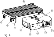
- a lifting device 22 On the electronic unit is a lifting device 22, in particular service claw for lifting the drive rollers 7, arranged.
- the drive rollers 7 can be raised relative to a surrounding portion of the electronic unit 5, which has a housing part 21.
- auxiliary rollers 20 which come into contact with the ground when lifting the drive rollers 7.
- the auxiliary rollers whose roller axis is aligned parallel to the traverse plane, are mounted on a bearing in a bearing receiving part, which in turn is rotatably mounted in the electronic unit 5, wherein the axis of rotation is parallel to the normal direction of the traverse plane.
- this electronic unit 5 Since auxiliary rollers 20 are arranged on the electronic unit 5, this electronic unit 5 is movable with the drive rollers 7 raised and can therefore be pulled out after disconnecting the connection to the receiving plate 6.
- the electronic unit 5 also includes the two electric motors which each drive a drive roller 7.
- the electric motors are hereby also executable as direct drives or geared motors.
- a sensor 2 for monitoring a security area On the receiving plate 6 and a sensor 2 for monitoring a security area is provided.
- the sensor signals are wired or wirelessly transmitted to a control electronics, which is arranged in the electronic unit 5.
- a control electronics which is arranged in the electronic unit 5.
- the control electronics such as switching off the drives, in particular electric motors, or limiting the speed of the drives and / or the speed of the handset to a safety value and / or displaying warning information and / or reporting warning information.
- An emergency stop switch 3 is arranged on the electronic unit 5. Alternatively or additionally, an emergency stop switch 3 can be arranged on the receiving plate.
- the electronic unit 5 has on its bottom side facing the bottom two spaced apart in the direction of travel transmitter heads 4, in particular each comprising a secondary winding on. In this way, therefore, the handset by means of a buried primary conductor inductively supplied with energy and / or information.
- the connecting region between the electronic unit 5 and the receiving plate 6 comprises a plain bearing whose axis of rotation is aligned parallel to the normal direction of the traverse plane.
- the receiving plate covers an area in the traverse plane which contains the area covered by the electronic unit 5 in the traverse plane, this area being a real subarea of the area covered by the receiving plate 6 in the traversing plane.
- a tracking antenna 8 is arranged so that the electronic unit 5 along a predetermined trajectory is feasible by an electrical conductor is laid in the ground along the trajectory.
- an optical or inductive tracking is executable, in which case the tracking antenna 8 as an optical sensor, which is provided for detecting an optically marked line instead of the conductor, or inductively coupled to the conductor secondary winding is executable.
- the electronic unit 5 also has a display unit 23 with input means for data input for control electronics. Thus, drive-related parameters can be input to the electronic unit 5 and / or displayed.
- a sliding bearing 50 is provided as a pivot bearing, whose axis of rotation is aligned in the normal direction to the traversing plane.
- a housing cover 40 is a part of the housing of the electronic unit 5 and is detachably attached to the remaining electronic unit 5 or hinged thereto.
- the remaining housing of the electronics unit is constructed like a trough, so that the housing cover 40 acts as a top or lid to this trough-like base.
- the receiving part 6 has a recess, so that electrical cables and a mating connector part can be passed for connection to the connector part 60, which is arranged on the electronic unit 5.
- the patch on the receiving part 6 load during transport with energy and / or information can be supplied.
- a signal lamp arranged on the receiving part can also be supplied with energy or it is a roller conveyor, wherein at least one of the rollers has an electrical drive, can be arranged on the receiving part 6 and supplied with energy from the electronic unit 5.
- the receiving plate 6 and the electronic unit 5 slide bearing is equipped with a rotation angle between the receiving plate 6 and the electronic unit 5 controlling or regulating to a desired angle out rotary drive.
- the receiving plate is durable even with variable direction of travel of the handsets in a desired orientation.
Landscapes
- Engineering & Computer Science (AREA)
- Transportation (AREA)
- Mechanical Engineering (AREA)
- Structural Engineering (AREA)
- Chemical & Material Sciences (AREA)
- Combustion & Propulsion (AREA)
- Civil Engineering (AREA)
- Life Sciences & Earth Sciences (AREA)
- Geology (AREA)
- Handcart (AREA)
- Current-Collector Devices For Electrically Propelled Vehicles (AREA)
Description
- Die Erfindung betrifft ein Mobilteil.
- Als Mobilteile sind Automobile oder Gabelstapler allgemein bekannt. Manche dieser Fahrzeuge weisen einen elektrischen Antrieb auf,
Aus derDE 201 20 808 U1 ist als nächstliegendem Stand der Technik ein Fördersystem mit zwischen Montagearbeitsplätzen verfahrbaren Flurförderfahrzeugen bekannt. - Aus der
EP 2 168 847 A1 ist ein automatisch geführte Fahrzeugantriebsvorrichtung bekannt. - Aus der
FR 2 449 578 A1 - Aus der
JP 2009 208527 A - Aus der
US 5 202 832 A ist ein Material-Handling-Automatisierungssystem bekannt, bei dem ein tragbares Transfermodul vorgesehen ist. - Aus der
DE 10 2009 007954 A1 ist ein Verfahren zur Wegsteuerung eines Fahrzeugs bekannt. - Aus der
US 5 170 351 A ist ein automatisch geführtes Fahrzeug bekannt und ein Verfahren zur Spurführung bekannt. - Aus der
US 2006/058921 A1 ist ein mobiler Roboter bekannt. - Aus der
US 4 972 917 ist eine Wagenfördereinheit bekannt. - Der Erfindung liegt daher die Aufgabe zugrunde, ein Mobilteil weiterzubilden, wobei ein einfaches Handling erreichbar sein soll, insbesondere eine Wartung des Antriebs oder der Elektronik einfach ausführbar sein soll.
- Erfindungsgemäß wird die Aufgabe bei dem Mobilteil nach den in Anspruch 1 angegebenen Merkmalen gelöst.
- Wichtige Merkmale der Erfindung bei dem Mobilteil sind, dass das Mobilteil eine Elektronikeinheit und eine Aufnahmeeinheit, insbesondere Aufnahmeplatte, aufweist,
wobei die Elektronikeinheit einen elektrischen Antrieb, insbesondere umfassend einen Elektromotor, und von dem elektrischen Antrieb antreibbare Antriebsrollen zum Bewegen des Mobilteils entlang einer Verfahrfläche, insbesondere also Verfahrebenenabschnitt, aufweist,
wobei
die Aufnahmeeinheit mittels Rollen, insbesondere Lenkrollen, abgestützt und/oder bewegbar ist zum Bewegen des Aufnahmeteils entlang der Verfahrfläche, insbesondere also Boden, insbesondere in verschiedene Richtungen,
wobei die Elektronikeinheit drehbar gelagert ist an der Aufnahmeeinheit, insbesondere wobei die Drehachse senkrecht zur Verfahrfläche. - Von Vorteil ist dabei, dass die Aufnahmeeinheit über Rollen auf der Verfahrfläche abgestützt und gehalten ist. Somit ist keine Gewichtskraft der Aufnahmeeinheit über die Elektronikeinheit an die Verfahrfläche abzuleiten. Die Elektronikeinheit weist selbst Antriebsrollen auf, so dass ihre Gewichtskraft über diese an die Verfahrfläche leitbar ist. Somit ist die Wartung der Elektronikeinheit einfach ausführbar, da die Aufnahmeeinheit hierzu nicht beeinflusst werden muss. Ein einfaches Entkoppeln der beiden Einheiten genügt.
- Bei einer vorteilhaften Ausgestaltung weist die Elektronikeinheit Hilfsrollen auf, mit welcher sie entlang der Verfahrfläche bewegbar ist nach Anheben der Antriebsrollen mittels einer an der Elektronikeinheit angeordneten Hebevorrichtung, insbesondere Servicekralle, zum Anheben der Antriebsrollen (7). Von Vorteil ist dabei, dass eine einfache Wartung erreichbar ist. Bei Deaktivieren, insbesondere Anheben der Antriebsrollen von der Verfahrfläche weg, der Antriebsrollen sind Hilfsrollen vorhanden, die die Gewichtskraft ableiten.
- Bei einer vorteilhaften Ausgestaltung ist die drehbare Lagerung der Elektronikeinheit am Aufnahmeteil mittels eines Gleitlagers ausgeführt. Von Vorteil ist dabei, dass ein kostengünstiges Drehlager verwendbar ist und Axialkräfte vom Lager aufnehmbar sind.
- Bei einer vorteilhaften Ausgestaltung ist an der Aufnahmeeinheit Nuten zur Befestigung einer Last und/oder eine Fördervorrichtung, insbesondere Rollbahn, für eine Last mit elektrisch antreibbaren und/oder nicht antreibbaren Rollen, oder eine Hubgabel, ein Hubtisch oder ein anderes Handlingsystem angeordnet,
insbesondere wobei die elektrische Versorgung der Fördervorrichtung von der Elektronikeinheit aus durchgeführt wird. Von Vorteil ist dabei, dass das Mobilteil zwischen zwei Förderbänder positionierbar ist und auf der Aufnahmeeinheit eine Fördervorrichtung als Last anbringbar ist, die dann das von den Förderbändern herangeförderten Transportgut in einfacher Weise aufnimmt. - Bei einer vorteilhaften Ausgestaltung weist das Gehäuse der Elektronikeinheit ein Unterteil, insbesondere wannenartige ausgeformtes Unterteil, und ein darauf aufgesetztes Oberteil, insbesondere Gehäusedeckel, auf,
insbesondere wobei das Gleitlager zwischen der Aufnahmeplatte und dem Unterteil angeordnet ist. Von Vorteil ist dabei, dass ein Abnehmen oder Aufklappen des Oberteils genügt, um die Elektronik und/oder den Antrieb zugänglich zu machen. - Bei einer vorteilhaften Ausgestaltung ist die Hebevorrichtung zum Anhebender Antriebsrollen derart ausgeführt ist, dass das Unterteil der Elektronikeinheit beim Anheben der Rollen das Unterteil sich derart der Verfahrfläche nähert, dass die Hilfsrollen die Verfahrfläche berühren. Von Vorteil ist dabei, dass das Abtrennen der Elektronikeinheit von der Aufnahmeeinheit in einfacher Weise ausführbar ist, indem die Einheiten im Bereich des Gleitlager entkoppelt werden. Vorzugsweise wird dies durch eine Hebevorrichtung bewirkt, die die Antriebsrollen anhebt und dabei einen am Elektronikeinheit herausragenden Achsabschnitt aus einer als Aufnahmebohrung fungierenden Ausnehmung in der Aufnahmeeinheit herausdrückt. Dabei ist vorteiligerweise die Antriebsrolle und/oder der zugehörige Antrieb von der restlichen Elektronikeinheit relativ bewegbar. An der restlichen Elektronikeinheit ist der herausragende Achsabschnitt angeordnet, so dass bei dem anheben die restliche Elektronikeinheit zur Verfahrfläche gedrückt wird und dabei der Achsabschnitt den Kontakt zur Aufnahmebohrung verliert, wodurch das Gleitlager aufgetrennt ist und somit die Elektronikeinheit auf den Hilfsrollen herausfahrbar ist.
- Bei einer vorteilhaften Ausgestaltung ist das Oberteil abnehmbar, insbesondere aufklappbar. Von Vorteil ist dabei, dass eine einfache Wartung ausführbar ist.
- Bei einer vorteilhaften Ausgestaltung weist die Aufnahmeplatte eine Ausnehmung zur Kabeldurchführung auf, so dass Kabel und/oder Steckverbinderteil hindurchführbar ist zur elektrischen Versorgung einer auf der Aufnahmeplatte aufgenommenen Last, insbesondere Förderbahn, Rollenbahn und/oder Signallampe. Von Vorteil ist dabei, dass die Last als elektrischer Verbraucher ausführbar ist.
- Bei einer vorteilhaften Ausgestaltung weist die Elektronikeinheit zumindest eine Sekundärwicklung, insbesondere eine von einem Übertragerkopf umfasste Sekundärwicklung, auf, die an einen in oder an der Verfahrfläche verlegten Primärleiter induktiv ankoppelbar ist, so dass die Elektronikeinheit, insbesondere samt deren elektrischer Antrieb, elektrisch versorgbar ist. Von Vorteil ist dabei, dass eine kontaktlose Energieversorgung ermöglicht ist und somit das Mobilteil in Anlagen der Nahrungsindustrie oder chemischen Industrie oder in explosionsgeschützter Umgebung einsetzbar ist
- Bei einer vorteilhaften Ausgestaltung weist die Elektronikeinheit ein Spurführungsmittel auf, mit welchem das Mobilteil entlang einer in der Verfahrfläche angeordneten Markierung oder entlang eines in der Verfahrfläche angeordneten Leitdrahtes führbar ist,
insbesondere wobei der Primärleiter auch als Leitdraht fungiert,
insbesondere wobei die bei der Spurführung verwendete Stromanteile eine höhere Frequenz aufweisen als die Frequenz des in den Primärleiter eingespeisten Stromes zur Übertragung von Versorgungsenergie für das Mobilteil. Von Vorteil ist dabei, dass eine einfache Bahnführung ermöglicht ist, ohne dass ein aufwendiges Navigationssystem installiert werden muss. - Bei einer vorteilhaften Ausgestaltung ist der Sekundärwicklung eine Kapazität derart in Reihe und/oder parallel zugeschaltet, dass die Resonanzfrequenz des so gebildeten Schwingkreises im Wesentlichen der Frequenz des in den Primärleiter zur Versorgung des Mobilteils eingeprägten Stromanteils entspricht. Von Vorteil ist dabei, dass ein hoher Wirkungsgrad erreichbar ist.
- Bei einer vorteilhaften Ausgestaltung ist an der Elektronikeinheit und/oder an der Aufnahmeplatte ein Not-Aus-Schalter angeordnet. Von Vorteil ist dabei, dass ein schnelles Abschalten ermöglicht ist.
- Bei einer vorteilhaften Ausgestaltung ist an der Aufnahmeplatte, insbesondere an einer Ecke der Aufnahmeplatte ein Sicherheitssensor zur Überwachung eines Sicherheitsbereichs angeordnet. Von Vorteil ist dabei, dass die Sicherheit erhöht ist.
- Bei einer vorteilhaften Ausgestaltung ist eine Arretiervorrichtung, insbesondere eine elektrisch, magnetisch oder mechanisch betätigbare Arretiervorrichtung zum Verbinden oder Trennen der Aufnahmeplatte von der Elektronikeinheit am Mobilteil vorgesehen, insbesondere an der Elektronikeinheit oder an der Aufnahmeplatte. Von Vorteil ist dabei, dass ein Trennen in einfacher Weise ermöglicht ist.
- Bei einer vorteilhaften Ausgestaltung umfasst die Arretiervorrichtung das Gleitlager oder aktiviert oder deaktiviert zumindest das Gleitlager oder trennt dieses auf. Von Vorteil ist dabei, dass ein einfaches Handling ausführbar ist.
- Weitere Vorteile ergeben sich aus den Unteransprüchen.
- Die Erfindung wird nun anhand von Abbildungen näher erläutert:
- In der
Figur 1 ein Mobilteil eines fahrerlosen Transportsystems, insbesondere automated guided vehicle AGV, also automatisch geführte Mobileinheit, in Draufsicht von unten gezeigt. - In der
Figur 2 ist eine zugehörige Seitenansicht gezeigt. - In der
Figur 3 ist eine zugehörige Schrägansicht gezeigt. - In der
Figur 4 ist das Mobilteil mit separierter Elektronikeinheit 5 gezeigt. - In der
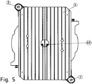
Figur 5 ist eine Draufsicht auf das Mobilteil gezeigt. -
Figur 6 zeigt die Lastaufnahme. - Das erfindungsgemäße Mobilteil ist ein flächengeführtes Fahrzeug und weist eine Aufnahmeplatte 6 zur Aufnahme einer Last auf. Dabei sind an der Oberseite, also der der Laste zugewandten Seite der Aufnahmeplatte 6, Nuten in die Aufnahmeplatte 6 eingearbeitet, so dass eine Befestigung der Last mit Nutensteinen oder dergleichen Befestigungsmitteln ermöglicht ist.
- Des Weiteren ist eine Kabelführung durch einen Bereich der Nuten zu einem Sensor vorgesehen.
- Außerdem weist die Aufnahmeplatte 6 eine Ausnehmung zur Durchführung einer elektrischen Anschlussvorrichtung, insbesondere Steckverbinderteil, und/oder eines elektrischen Kabels auf, so dass eine elektrische Versorgung der Last und/oder eine Datenübertragung zur an der Unterseite der Aufnahmeplatte 6 angeordneten Elektronikeinheit 5 ermöglicht ist.
- An der Aufnahmeplatte 6 sind Lenkrollen 1 verbunden. Diese Lenkrollen 1 sind also in ihrer Fahrtrichtung frei, indem das Lager der Lenkrollen selbst drehbar gelagert ist an der Aufnahmeplatte 6, wobei die Drehachse parallel zur Normalenrichtung der Platte ausgerichtet ist. Bei einer weiteren erfindungsgemäßen Ausführung sind zusätzlich Anschläge bei einer Verdrehung der Rollen um einen Winkelbetrag von etwa 90° vorgesehen.
- Wie in der Figur gezeigt, ist die Elektronikeinheit 5 mittels eines Gleitlagers, dessen Drehachse ebenfalls in Normalenrichtung der Ebene der Aufnahmeplatte 6 und/oder der Verfahrebene ausgerichtet ist, drehbar gelagert an der Aufnahmeplatte 6.
- An der Unterseite der Elektronikeinheit 5 sind zwei Antriebsrollen 7 angeordnet, die jeweils von einem elektrischen Antrieb, insbesondere aufweisend einen Elektromotor, antreibbar sind. Bei unterschiedlicher Drehzahl wird daher die Fahrtrichtung geändert, bei synchroner Drehzahl wird die Elektronikeinheit 5 und auch die an ihr drehbar gelagerte Aufnahmeplatte 6 in Fahrtrichtung bewegt.
- Die Lenkrollen 1 passen sich in ihrer Ausrichtung der jeweiligen, von den Antriebsrollen vorgegebenen Fahrtrichtung an.
- An der Elektronikeinheit ist eine Hebevorrichtung 22, insbesondere Servicekralle zum Anheben der Antriebsrollen 7, angeordnet. Somit sind die Antriebsrollen 7 relativ zu einem umgebenden Abschnitt der Elektronikeinheit 5, der ein Gehäuseteil 21 aufweist, anhebbar. Beim Anheben verlieren die Antriebsrollen 7 den Bodenkontakt und die Elektronikeinheit 5 wird von Hilfsrollen 20 getragen, welche beim Anheben der Antriebsrollen 7 in Bodenkontakt kommen. Die Hilfsrollen, deren Rollenachse parallel zur Verfahrebene ausgerichtet ist, sind über ein Lager in einem Lageraufnahmeteil gelagert, das wiederum drehbar gelagert ist in der Elektronikeinheit 5, wobei die Drehachse parallel zur Normalenrichtung der Verfahrebene ist.
- Da an der Elektronikeinheit 5 Hilfsrollen 20 angeordnet sind, ist diese Elektronikeinheit 5 bei angehobenen Antriebsrollen 7 bewegbar und kann daher nach Trennen der Verbindung zur Aufnahmeplatte 6 unter dieser herausgezogen werden.
- Die Elektronikeinheit 5 umfasst auch die beiden Elektromotoren, welche jeweils eine Antriebsrolle 7 antreiben. Die Elektromotoren sind hierbei auch als Direktantriebe oder Getriebemotoren ausführbar.
- An der Aufnahmeplatte 6 ist auch ein Sensor 2 zur Überwachung eines Sicherheitsbereichs vorgesehen. Die Sensorsignale werden drahtgebunden oder drahtlos übertragen zu einer Steuerelektronik, welche in der Elektronikeinheit 5 angeordnet ist. Somit ist bei Detektion eines Hindernisses oder Eindringen eines Objektes oder Menschen im Sicherheitsbereich eine entsprechende Aktion von der Steuerelektronik auslösbar, wie beispielsweise ein Abschalten der Antriebe, insbesondere Elektromotoren, oder ein Begrenzen der Drehzahl der Antriebe und/oder der Geschwindigkeit des Mobilteils auf einen Sicherheitswert und/oder das Anzeigen einer Warninformation und/oder Weitermelden einer Warninformation.
- Ein Not-Aus-Schalter 3 ist an der Elektronikeinheit 5 angeordnet. Alternativ oder zusätzlich ist auch ein Not-Aus-Schalter 3 an der Aufnahmeplatte anordenbar.
- Somit ist mittels des Not-Aus-Schalters 3 im Notfall ein Abschalten ermöglicht und somit die Sicherheit erhöht.
- Des Weiteren weist die Elektronikeinheit 5 an ihrer dem Boden zugewandten Unterseite zwei voneinander in Fahrtrichtung beabstandete Übertragerköpfe 4, insbesondere jeweils umfassend eine Sekundärwicklung, auf. Auf diese Weise ist also das Mobilteil mittels eines bodenverlegten Primärleiters induktiv mit Energie und/oder Information versorgbar.
- Infolge der Beabstandung der beiden Übertragerköpfe 4 ist ein unversorgter Bereich überbrückbar. Beispielsweise ist somit die Versorgung des Mobilteils ununterbrochen, wenn die Versorgung von einem ersten Primärleiter auf einen zweiten Primärleiter gewechselt wird und während das Mobilteil sich im Übergangsbereich befindet.
- Der Verbindungsbereich zwischen Elektronikeinheit 5 und Aufnahmeplatte 6 umfasst ein Gleitlager, dessen Drehachse parallel zur Normalenrichtung der Verfahrebene ausgerichtet ist. Durch die somit gegenüber der Aufnahmeplatte 6 drehbare Anordnung der Elektronikeinheit 5 ist es ermöglicht, dass bei einer Veränderung der Fahrtrichtung der Elektronikeinheit 5 in der Verfahrebene die Aufnahmeplatte 6 unverändert ausgerichtet bleibt oder nur langsam ihre Ausrichtung ändert. Insbesondere bei ruckartiger Fahrtrichtungsänderung bleibt die Ausrichtungsänderung der Aufnahmeplatte 6 ruckfrei oder zumindest ruckbegrenzt. Außerdem ist zum Einparken in einer Parklücke am Fahrbahnrand die Elektronikeinheit um 90° zur Fahrtrichtung verdrehbar und dann ein quer ausgeführtes Einparken ermöglicht. Dabei bleibt die Aufnahmeplatte 6 in Fahrtrichtung ausgerichtet und wird sozusagen seitlich in die Parklücke verschoben.
- Die Aufnahmeplatte überdeckt einen Bereich in der Verfahrebene, welcher den von der Elektronikeinheit 5 in der Verfahrebene abgedeckten Bereich enthält, wobei dieser Bereich ein echter Teilbereich des von der Aufnahmeplatte 6 in der Verfahrebene abgedeckten Bereichs ist.
- An der Elektronikeinheit 5 ist auch eine Spurführungsantenne 8 angeordnet, so dass die Elektronikeinheit 5 entlang einer vorgegebenen Bahnkurve führbar ist, indem im Boden ein elektrischer Leiter verlegt ist entlang der Bahnkurve. Statt einer solchen Funkwellengestützten Spurführung ist aber auch eine optische oder induktive Spurführung ausführbar, wobei dann die Spurführungsantenne 8 als optischer Sensor, welcher zur Detektion einer optisch markierten Linie anstatt des Leiters vorgesehen ist, beziehungsweise induktiv an den Leiter gekoppelte Sekundärwicklung ausführbar ist.
- Die Elektronikeinheit 5 weist außerdem eine Anzeigeeinheit 23 mit Eingabemitteln zur Dateneingabe für Steuerelektronik auf. Somit sind antriebsbezogene Parameter an der Elektronikeinheit 5 eingebbar und/oder anzeigbar.
- Zwischen Aufnahmeplatte 6 und Elektronikeinheit 5, insbesondere Gehäuseteil 21, ist als Drehlager ein Gleitlager 50 vorgesehen, dessen Drehachse in Normalenrichtung zur Verfahrebene ausgerichtet ist.
- Ein Gehäusedeckel 40 ist ein Teil des Gehäuses der Elektronikeinheit 5 und ist abnehmbar von der restlichen Elektronikeinheit 5 oder aufklappbar an dieser befestigt.
- Das restliche Gehäuse der Elektronikeinheit ist wannenartig aufgebaut, so dass der Gehäusedeckel 40 als Oberteil oder Deckel zu diesem wannenartigen Unterteil fungiert.
- Das Aufnahmeteil 6 weist eine Ausnehmung auf, so dass elektrische Kabel und ein Gegensteckverbinderteil hindurchführbar sind zur Verbindung mit dem Steckverbinderteil 60, welches an der Elektronikeinheit 5 angeordnet ist. Dabei ist die auf dem Aufnahmeteil 6 aufgesetzte Last während des Transportes mit Energie und/oder Information versorgbar. Alternativ oder zusätzlich ist auch eine am Aufnahmeteil angeordnete Signallampe mit Energie versorgbar oder es ist eine Rollenbahn, wobei zumindest eine der Rollen einen elektrischen Antrieb aufweist, auf dem Aufnahmeteil 6 anordenbar und mit Energie aus der Elektronikeinheit 5 versorgbar.
- Bei weiteren erfindungsgemäßen Ausführungsbeispielen ist das zwischen Aufnahmeplatte 6 und Elektronikeinheit 5 angeordnete Gleitlager mit einem den Verdrehwinkel zwischen der Aufnahmeplatte 6 und der Elektronikeinheit 5 steuernden oder auf einen Sollwinkel hin regelnden Drehantrieb ausgestattet. Auf diese Weise ist die Aufnahmeplatte auch bei veränderlicher Fahrtrichtung des Mobilteile in einer gewünschten Ausrichtung haltbar.
-
- 1
- Lenkrollen
- 2
- Sensor zur Überwachung eines Sicherheitsbereichs
- 3
- Not-Aus-Schalter
- 4
- Übertragerkopf, insbesondere umfassend Sekundärwicklung
- 5
- drehbare Elektronikeinheit
- 6
- Aufnahmeplatte zur Aufnahme einer Last
- 7
- Antriebsrolle, angetrieben durch elektrischen Antrieb
- 8
- Spurführungsantenne
- 10
- Begrenzungsmittel
- 20
- Hilfsrollen
- 21
- Gehäuseteil für drehbare Elektronikeinheit 5
- 22
- Hebevorrichtung, insbesondere Servicekralle, zum Anheben der Antriebsrollen 7
- 23
- Anzeigeeinheit mit Eingabemitteln zur Dateneingabe für Steuerelektronik
- 40
- Gehäusedeckel
- 50
- Gleitlager zwischen Aufnahmeplatte 6 und Gehäuseteil 21
- 51
- Gleitlager zwischen Aufnahmeplatte 6 und Gehäuseteil 21
- 60
- Steckverbinderteil
Claims (14)
- Mobilteil,
aufweisend eine Elektronikeinheit (5) und eine Aufnahmeeinheit, insbesondere Aufnahmeplatte (6),
wobei die Elektronikeinheit einen elektrischen Antrieb, insbesondere umfassend einen Elektromotor, und von dem elektrischen Antrieb antreibbare Antriebsrollen (7) zum Bewegen des Mobilteils entlang einer Verfahrfläche, insbesondere also Verfahrebenenabschnitt, aufweist,
wobei die Aufnahmeeinheit mittels Rollen, insbesondere Lenkrollen (1), abgestützt und/oder bewegbar ist zum Bewegen des Aufnahmeteils entlang der Verfahrfläche, insbesondere also Boden, insbesondere in verschiedene Richtungen,
wobei die Elektronikeinheit drehbar gelagert ist an der Aufnahmeeinheit, insbesondere wobei die Drehachse senkrecht zur Verfahrfläche,
dadurch gekennzeichnet, dass die Elektronikeinheit Hilfsrollen (20) aufweist, mit welcher sie entlang der Verfahrfläche bewegbar ist nach Anheben der Antriebsrollen mittels einer an der Elektronikeinheit angeordneten Hebevorrichtung (22), insbesondere Servicekralle, zum Anheben der Antriebsrollen (7). - Mobilteil nach Anspruch 1,
dadurch gekennzeichnet, dass
die drehbare Lagerung der Elektronikeinheit am Aufnahmeteil mittels eines Gleitlagers (50, 51) ausgeführt ist. - Mobilteil nach mindestens einem der vorangegangenen Ansprüche,
dadurch gekennzeichnet, dass
an der Aufnahmeeinheit Nuten zur Befestigung einer Last und/oder eine Fördervorrichtung, insbesondere Rollbahn, für eine Last mit elektrisch antreibbaren und/oder nicht antreibbaren Rollen, angeordnet ist,
insbesondere wobei die elektrische Versorgung der Fördervorrichtung von der Elektronikeinheit aus durchgeführt wird. - Mobilteil nach mindestens einem der vorangegangenen Ansprüche,
dadurch gekennzeichnet, dass das Gehäuse (21) der Elektronikeinheit ein Unterteil, insbesondere wannenartige ausgeformtes Unterteil, und ein darauf aufgesetztes Oberteil, insbesondere Gehäusedeckel (40), aufweist, insbesondere wobei das Gleitlager zwischen der Aufnahmeeinheit und dem Unterteil angeordnet ist. - Mobilteil nach mindestens einem der vorangegangenen Ansprüche,
dadurch gekennzeichnet, dass
die Hebevorrichtung zum Anhebender Antriebsrollen derart ausgeführt ist, dass das Unterteil der Elektronikeinheit beim Anheben der Rollen das Unterteil sich derart der Verfahrfläche nähert, dass die Hilfsrollen die Verfahrfläche berühren. - Mobilteil nach Anspruch 4,
dadurch gekennzeichnet, dass
das Oberteil abnehmbar ist, insbesondere aufklappbar. - Mobilteil nach mindestens einem der vorangegangenen Ansprüche,
dadurch gekennzeichnet, dass
die Aufnahmeeinheit eine Ausnehmung zur Kabeldurchführung aufweist, so dass Kabel und/oder Steckverbinderteil (60) hindurchführbar ist zur elektrischen Versorgung einer auf der Aufnahmeeinheit aufgenommenen Last, insbesondere Förderbahn, Rollenbahn und/oder Signallampe. - Mobilteil nach mindestens einem der vorangegangenen Ansprüche,
dadurch gekennzeichnet, dass
die Elektronikeinheit zumindest eine Sekundärwicklung, insbesondere eine von einem Übertragerkopf umfasste Sekundärwicklung, aufweist, die an einen in oder an der Verfahrfläche verlegten Primärleiter induktiv ankoppelbar ist, so dass die Elektronikeinheit, insbesondere samt deren elektrischer Antrieb, elektrisch versorgbar ist. - Mobilteil nach mindestens einem der vorangegangenen Ansprüche,
dadurch gekennzeichnet, dass
die Elektronikeinheit ein Spurführungsmittel (8) aufweist, mit welchem das Mobilteil entlang einer in der Verfahrfläche angeordneten Markierung oder entlang eines in der Verfahrfläche angeordneten Leitdrahtes führbar ist,
insbesondere wobei der Primärleiter auch als Leitdraht fungiert,
insbesondere wobei die bei der Spurführung verwendete Stromanteile eine höhere Frequenz aufweisen als die Frequenz des in den Primärleiter eingespeisten Stromes zur Übertragung von Versorgungsenergie für das Mobilteil. - Mobilteil nach Anspruch 8,
dadurch gekennzeichnet, dass
der Sekundärwicklung eine Kapazität derart in Reihe und/oder parallel zugeschaltet ist, dass die Resonanzfrequenz des so gebildeten Schwingkreises im Wesentlichen der Frequenz des in den Primärleiter zur Versorgung des Mobilteils eingeprägten Stromanteils. - Mobilteil nach mindestens einem der vorangegangenen Ansprüche,
dadurch gekennzeichnet, dass an der Elektronikeinheit und/oder an der Aufnahmeeinheit ein Not-Aus-Schalter (3) angeordnet ist - Mobilteil nach mindestens einem der vorangegangenen Ansprüche,
dadurch gekennzeichnet, dass
an der Aufnahmeeinheit, insbesondere an einer Ecke der Aufnahmeeinheit ein Sicherheitssensor (2) zur Überwachung eines Sicherheitsbereichs angeordnet ist. - Mobilteil nach mindestens einem der vorangegangenen Ansprüche,
dadurch gekennzeichnet, dass
eine Arretiervorrichtung, insbesondere eine elektrisch, magnetisch oder mechanisch betätigbare Arretiervorrichtung zum Verbinden oder Trennen der Aufnahmeeinheit von der Elektronikeinheit am Mobilteil vorgesehen ist, insbesondere an der Elektronikeinheit oder an der Aufnahmeeinheit. - Mobilteil nach einem der Ansprüche 2 oder 13,
dadurch gekennzeichnet, dass
die Arretiervorrichtung das Gleitlager umfasst oder zumindest das Gleitlager aktiviert oder deaktiviert, insbesondere auftrennt.
Applications Claiming Priority (2)
| Application Number | Priority Date | Filing Date | Title |
|---|---|---|---|
| DE102011110196.2A DE102011110196B4 (de) | 2011-08-16 | 2011-08-16 | Mobilteil |
| PCT/EP2012/002829 WO2013023721A1 (de) | 2011-08-16 | 2012-07-05 | Mobilteil |
Publications (2)
| Publication Number | Publication Date |
|---|---|
| EP2744741A1 EP2744741A1 (de) | 2014-06-25 |
| EP2744741B1 true EP2744741B1 (de) | 2017-05-31 |
Family
ID=46551480
Family Applications (1)
| Application Number | Title | Priority Date | Filing Date |
|---|---|---|---|
| EP12738032.7A Active EP2744741B1 (de) | 2011-08-16 | 2012-07-05 | Mobilteil |
Country Status (3)
| Country | Link |
|---|---|
| EP (1) | EP2744741B1 (de) |
| DE (1) | DE102011110196B4 (de) |
| WO (1) | WO2013023721A1 (de) |
Cited By (5)
| Publication number | Priority date | Publication date | Assignee | Title |
|---|---|---|---|---|
| WO2020187457A1 (en) | 2019-03-20 | 2020-09-24 | Asti Mobile Robotics, S.A.U | Autonomous omnidirectional drive unit |
| WO2020200697A1 (en) | 2019-03-29 | 2020-10-08 | Universitat Politecnica De Catalunya | Compact autonomous omnidirectional drive unit |
| DE102020108095A1 (de) | 2020-03-24 | 2021-09-30 | Schaeffler Technologies AG & Co. KG | Fahrzeugantriebseinheit und Fahrzeug mit einer Fahrzeugantriebseinheit |
| DE102024129816B3 (de) * | 2024-07-15 | 2025-07-24 | Sew-Eurodrive Gmbh & Co Kg | Fördersystem, insbesondere Transportsystem, mit Mobilteilen |
| WO2026017345A1 (de) | 2024-07-15 | 2026-01-22 | Sew-Eurodrive Gmbh & Co Kg | Fördersystem, insbesondere transportsystem, mit mobilteilen |
Families Citing this family (10)
| Publication number | Priority date | Publication date | Assignee | Title |
|---|---|---|---|---|
| DE102013016381A1 (de) | 2013-09-30 | 2015-04-02 | Grenzebach Maschinenbau Gmbh | Transportfahrzeug und Verfahren zum störungsfreien Transport von Lastregalen in Werkshallen mit Funkabschattungen und mit teilweise autonomem Fahrbetrieb |
| DE102013020833A1 (de) | 2013-12-12 | 2015-06-18 | Grenzebach Maschinenbau Gmbh | Fahrerloses Transportfahrzeug für den sicheren Transport schwerer Lasten |
| DE202013011145U1 (de) | 2013-12-12 | 2014-01-29 | Grenzebach Maschinenbau Gmbh | Fahrerloses Transportfahrzeug für den sicheren Transport schwerer Lasten |
| CN105172562B (zh) * | 2015-09-16 | 2017-11-10 | 成都四威高科技产业园有限公司 | 一种带有悬挂机构的agv车用底盘 |
| CN106915627B (zh) * | 2017-01-25 | 2018-12-21 | 江山科锐普电子科技有限公司 | 自动物流搬运车 |
| DE102018006589A1 (de) | 2017-09-08 | 2019-03-14 | Sew-Eurodrive Gmbh & Co. Kg | System, aufweisend eine Transporteinheit und ein Mobilteil, und Verfahren zum Betreiben eines Systems |
| CN111148716B (zh) * | 2017-09-29 | 2022-07-01 | Roeq机器人设备有限公司 | 用于连接自主移动机器人的系统 |
| EP3740400A2 (de) * | 2018-01-18 | 2020-11-25 | Sew-Eurodrive GmbH & Co. KG | Mobilteil mit zumindest einem modul und verfahren zum betreiben eines mobilteils |
| USD902272S1 (en) | 2019-07-11 | 2020-11-17 | Asti Mobile Robotics Sau | Automatic guided vehicle |
| CN113090864B (zh) * | 2021-04-06 | 2023-04-14 | 苏州默斯肯智能科技有限公司 | 管道机器人航向保证系统及航向修正方法 |
Family Cites Families (14)
| Publication number | Priority date | Publication date | Assignee | Title |
|---|---|---|---|---|
| IT978377B (it) * | 1973-01-23 | 1974-09-20 | Folco Z | Struttura mobile con raggio di curvatura di valore zero |
| FR2449578A1 (fr) | 1979-02-21 | 1980-09-19 | Billaut Jean Marie | Chariot automoteur a translation orientable |
| JPS5938176A (ja) | 1982-08-24 | 1984-03-01 | Mitsubishi Electric Corp | 走行台車 |
| US4972917A (en) * | 1989-03-30 | 1990-11-27 | Matsushita Electric Industrial Co., Ltd. | Carriage conveying equipment |
| US5170351A (en) * | 1990-09-18 | 1992-12-08 | Matushita Electric Industrial Co., Ltd. | Automatic guided vehicle and method for controlling travel thereof |
| US5202832A (en) * | 1991-01-29 | 1993-04-13 | R. R. Donnelley & Sons Co. | Material handling automation system using portable transfer module |
| JP3055250B2 (ja) | 1991-09-17 | 2000-06-26 | 神鋼電機株式会社 | 全方向移動台車 |
| DE20120808U1 (de) * | 2001-12-21 | 2003-04-30 | Groh, Wolfgang, Prof. Dipl.-Ing., 45149 Essen | Fördersystem mit zwischen Montagearbeitsplätzen verfahrbaren Flurförderfahrzeugen sowie Schienensystem und Spannvorrichtung hierfür |
| US20060058921A1 (en) | 2004-09-13 | 2006-03-16 | Tamao Okamoto | Mobile robot |
| US7402018B2 (en) | 2004-10-14 | 2008-07-22 | Kiva Systems, Inc. | Inventory system with mobile drive unit and inventory holder |
| DE102007002242B4 (de) | 2007-01-10 | 2018-06-21 | Sew-Eurodrive Gmbh & Co Kg | System, insbesondere fahrerloses Transportfahrzeug |
| JP2009208527A (ja) | 2008-03-03 | 2009-09-17 | Nobuaki Ikuta | 移動方向自在電気駆動台車 |
| JP5305810B2 (ja) * | 2008-09-26 | 2013-10-02 | 愛知機械テクノシステム株式会社 | 無人搬送車 |
| DE102009007954A1 (de) * | 2009-02-06 | 2010-08-19 | Sew-Eurodrive Gmbh & Co. Kg | Verfahren und Vorrichtung zur Wegsteuerung eines Fahrzeuges |
-
2011
- 2011-08-16 DE DE102011110196.2A patent/DE102011110196B4/de active Active
-
2012
- 2012-07-05 EP EP12738032.7A patent/EP2744741B1/de active Active
- 2012-07-05 WO PCT/EP2012/002829 patent/WO2013023721A1/de not_active Ceased
Cited By (7)
| Publication number | Priority date | Publication date | Assignee | Title |
|---|---|---|---|---|
| WO2020187457A1 (en) | 2019-03-20 | 2020-09-24 | Asti Mobile Robotics, S.A.U | Autonomous omnidirectional drive unit |
| EP3712102B1 (de) * | 2019-03-20 | 2022-05-11 | Asti Mobile Robotics, S.A.U. | Omnidirektionales autonomes fahrzeug |
| WO2020200697A1 (en) | 2019-03-29 | 2020-10-08 | Universitat Politecnica De Catalunya | Compact autonomous omnidirectional drive unit |
| DE102020108095A1 (de) | 2020-03-24 | 2021-09-30 | Schaeffler Technologies AG & Co. KG | Fahrzeugantriebseinheit und Fahrzeug mit einer Fahrzeugantriebseinheit |
| WO2021190687A1 (de) | 2020-03-24 | 2021-09-30 | Schaeffler Technologies AG & Co. KG | Fahrzeugantriebseinheit und fahrzeug mit einer fahrzeugantriebseinheit |
| DE102024129816B3 (de) * | 2024-07-15 | 2025-07-24 | Sew-Eurodrive Gmbh & Co Kg | Fördersystem, insbesondere Transportsystem, mit Mobilteilen |
| WO2026017345A1 (de) | 2024-07-15 | 2026-01-22 | Sew-Eurodrive Gmbh & Co Kg | Fördersystem, insbesondere transportsystem, mit mobilteilen |
Also Published As
| Publication number | Publication date |
|---|---|
| DE102011110196A1 (de) | 2013-02-21 |
| DE102011110196B4 (de) | 2023-05-11 |
| EP2744741A1 (de) | 2014-06-25 |
| WO2013023721A1 (de) | 2013-02-21 |
Similar Documents
| Publication | Publication Date | Title |
|---|---|---|
| DE102011110196B4 (de) | Mobilteil | |
| EP3445527B1 (de) | Fertigungsanlage mit einem transportsystem zum transportieren eines behältnisses und verfahren zum betreiben einer fertigungsanlage mit einem transportsystem | |
| DE202019005946U1 (de) | Handhabungsroboter | |
| EP2401661B1 (de) | Förderanlage zum fördern von vereinzelten stückgütern | |
| DE68917157T2 (de) | Einrichtung zur übertragung von energie. | |
| EP3391168B1 (de) | Transportsystem und verfahren zum betreiben eines transportsystems | |
| DE102011100281C5 (de) | Transportsystem für einen Transport von Transportgut und Verfahren | |
| DE102008006170B4 (de) | Vorrichtung zur Handhabung von Gegenständen | |
| EP3080672A2 (de) | Fahrerloses transportfahrzeug für den transport schwerer lasten auf lafetten und verfahren zum betrieb des transportfahrzeugs | |
| DE102019001125B4 (de) | Fördereinrichtung für Ladungsträger mit integrierter Kollisionsdetektion | |
| EP2122431B1 (de) | System, insbesondere fahrerloses transportfahrzeug | |
| EP3523221B1 (de) | Regalbediengerät und regallagersystem mit verbesserter zugänglichkeit und gewichtsverteilung | |
| DE102011109532A1 (de) | Anlage und Verfahren zum Betreiben einer Anlage | |
| DE102012006412B4 (de) | Transportsystem | |
| WO2014032821A1 (de) | Verfahren und vorrichtung zur handhabung von bedruckstoffgebinden in einem bedruckstoffversorgungssystem einer eine druckmaschine umfassenden druckanlage | |
| EP1763449A1 (de) | Spurgeführtes transportsystem | |
| DE102013018268A1 (de) | Transportsystem | |
| EP3924291B1 (de) | Fördereinrichtung für ladungsträger | |
| EP2697110B1 (de) | Transportsystem | |
| AT513977A4 (de) | Anordnung und Verfahren zum Betrieb eines Regalbediengeräts | |
| WO2023072349A1 (de) | Fahrerloses transportfahrzeug | |
| CN103342313A (zh) | 重载智能大比例升降小车 | |
| EP1065126B1 (de) | Förderanlage zum Fördern, Verschieben, Verteilen und Positionieren von Eisenbahnwaggons | |
| EP4365112A1 (de) | Lagereinrichtung für werkstoffplatten | |
| DE102021114914A1 (de) | Robotersystem mit einem verfahrbaren Roboter |
Legal Events
| Date | Code | Title | Description |
|---|---|---|---|
| PUAI | Public reference made under article 153(3) epc to a published international application that has entered the european phase |
Free format text: ORIGINAL CODE: 0009012 |
|
| 17P | Request for examination filed |
Effective date: 20140317 |
|
| AK | Designated contracting states |
Kind code of ref document: A1 Designated state(s): AL AT BE BG CH CY CZ DE DK EE ES FI FR GB GR HR HU IE IS IT LI LT LU LV MC MK MT NL NO PL PT RO RS SE SI SK SM TR |
|
| DAX | Request for extension of the european patent (deleted) | ||
| GRAP | Despatch of communication of intention to grant a patent |
Free format text: ORIGINAL CODE: EPIDOSNIGR1 |
|
| INTG | Intention to grant announced |
Effective date: 20170109 |
|
| GRAS | Grant fee paid |
Free format text: ORIGINAL CODE: EPIDOSNIGR3 |
|
| GRAA | (expected) grant |
Free format text: ORIGINAL CODE: 0009210 |
|
| STAA | Information on the status of an ep patent application or granted ep patent |
Free format text: STATUS: THE PATENT HAS BEEN GRANTED |
|
| AK | Designated contracting states |
Kind code of ref document: B1 Designated state(s): AL AT BE BG CH CY CZ DE DK EE ES FI FR GB GR HR HU IE IS IT LI LT LU LV MC MK MT NL NO PL PT RO RS SE SI SK SM TR |
|
| REG | Reference to a national code |
Ref country code: CH Ref legal event code: EP Ref country code: GB Ref legal event code: FG4D Free format text: NOT ENGLISH Ref country code: CH Ref legal event code: NV Representative=s name: HEPP WENGER RYFFEL AG, CH |
|
| REG | Reference to a national code |
Ref country code: FR Ref legal event code: PLFP Year of fee payment: 6 |
|
| REG | Reference to a national code |
Ref country code: AT Ref legal event code: REF Ref document number: 897265 Country of ref document: AT Kind code of ref document: T Effective date: 20170615 |
|
| REG | Reference to a national code |
Ref country code: IE Ref legal event code: FG4D Free format text: LANGUAGE OF EP DOCUMENT: GERMAN |
|
| REG | Reference to a national code |
Ref country code: DE Ref legal event code: R096 Ref document number: 502012010446 Country of ref document: DE |
|
| REG | Reference to a national code |
Ref country code: NL Ref legal event code: FP |
|
| REG | Reference to a national code |
Ref country code: LT Ref legal event code: MG4D |
|
| PG25 | Lapsed in a contracting state [announced via postgrant information from national office to epo] |
Ref country code: FI Free format text: LAPSE BECAUSE OF FAILURE TO SUBMIT A TRANSLATION OF THE DESCRIPTION OR TO PAY THE FEE WITHIN THE PRESCRIBED TIME-LIMIT Effective date: 20170531 Ref country code: GR Free format text: LAPSE BECAUSE OF FAILURE TO SUBMIT A TRANSLATION OF THE DESCRIPTION OR TO PAY THE FEE WITHIN THE PRESCRIBED TIME-LIMIT Effective date: 20170901 Ref country code: ES Free format text: LAPSE BECAUSE OF FAILURE TO SUBMIT A TRANSLATION OF THE DESCRIPTION OR TO PAY THE FEE WITHIN THE PRESCRIBED TIME-LIMIT Effective date: 20170531 Ref country code: LT Free format text: LAPSE BECAUSE OF FAILURE TO SUBMIT A TRANSLATION OF THE DESCRIPTION OR TO PAY THE FEE WITHIN THE PRESCRIBED TIME-LIMIT Effective date: 20170531 Ref country code: HR Free format text: LAPSE BECAUSE OF FAILURE TO SUBMIT A TRANSLATION OF THE DESCRIPTION OR TO PAY THE FEE WITHIN THE PRESCRIBED TIME-LIMIT Effective date: 20170531 Ref country code: NO Free format text: LAPSE BECAUSE OF FAILURE TO SUBMIT A TRANSLATION OF THE DESCRIPTION OR TO PAY THE FEE WITHIN THE PRESCRIBED TIME-LIMIT Effective date: 20170831 |
|
| PG25 | Lapsed in a contracting state [announced via postgrant information from national office to epo] |
Ref country code: RS Free format text: LAPSE BECAUSE OF FAILURE TO SUBMIT A TRANSLATION OF THE DESCRIPTION OR TO PAY THE FEE WITHIN THE PRESCRIBED TIME-LIMIT Effective date: 20170531 Ref country code: LV Free format text: LAPSE BECAUSE OF FAILURE TO SUBMIT A TRANSLATION OF THE DESCRIPTION OR TO PAY THE FEE WITHIN THE PRESCRIBED TIME-LIMIT Effective date: 20170531 Ref country code: IS Free format text: LAPSE BECAUSE OF FAILURE TO SUBMIT A TRANSLATION OF THE DESCRIPTION OR TO PAY THE FEE WITHIN THE PRESCRIBED TIME-LIMIT Effective date: 20170930 Ref country code: BG Free format text: LAPSE BECAUSE OF FAILURE TO SUBMIT A TRANSLATION OF THE DESCRIPTION OR TO PAY THE FEE WITHIN THE PRESCRIBED TIME-LIMIT Effective date: 20170831 Ref country code: SE Free format text: LAPSE BECAUSE OF FAILURE TO SUBMIT A TRANSLATION OF THE DESCRIPTION OR TO PAY THE FEE WITHIN THE PRESCRIBED TIME-LIMIT Effective date: 20170531 |
|
| PG25 | Lapsed in a contracting state [announced via postgrant information from national office to epo] |
Ref country code: DK Free format text: LAPSE BECAUSE OF FAILURE TO SUBMIT A TRANSLATION OF THE DESCRIPTION OR TO PAY THE FEE WITHIN THE PRESCRIBED TIME-LIMIT Effective date: 20170531 Ref country code: RO Free format text: LAPSE BECAUSE OF FAILURE TO SUBMIT A TRANSLATION OF THE DESCRIPTION OR TO PAY THE FEE WITHIN THE PRESCRIBED TIME-LIMIT Effective date: 20170531 Ref country code: CZ Free format text: LAPSE BECAUSE OF FAILURE TO SUBMIT A TRANSLATION OF THE DESCRIPTION OR TO PAY THE FEE WITHIN THE PRESCRIBED TIME-LIMIT Effective date: 20170531 Ref country code: SK Free format text: LAPSE BECAUSE OF FAILURE TO SUBMIT A TRANSLATION OF THE DESCRIPTION OR TO PAY THE FEE WITHIN THE PRESCRIBED TIME-LIMIT Effective date: 20170531 Ref country code: EE Free format text: LAPSE BECAUSE OF FAILURE TO SUBMIT A TRANSLATION OF THE DESCRIPTION OR TO PAY THE FEE WITHIN THE PRESCRIBED TIME-LIMIT Effective date: 20170531 |
|
| PG25 | Lapsed in a contracting state [announced via postgrant information from national office to epo] |
Ref country code: PL Free format text: LAPSE BECAUSE OF FAILURE TO SUBMIT A TRANSLATION OF THE DESCRIPTION OR TO PAY THE FEE WITHIN THE PRESCRIBED TIME-LIMIT Effective date: 20170531 Ref country code: SM Free format text: LAPSE BECAUSE OF FAILURE TO SUBMIT A TRANSLATION OF THE DESCRIPTION OR TO PAY THE FEE WITHIN THE PRESCRIBED TIME-LIMIT Effective date: 20170531 |
|
| REG | Reference to a national code |
Ref country code: DE Ref legal event code: R097 Ref document number: 502012010446 Country of ref document: DE |
|
| PLBE | No opposition filed within time limit |
Free format text: ORIGINAL CODE: 0009261 |
|
| STAA | Information on the status of an ep patent application or granted ep patent |
Free format text: STATUS: NO OPPOSITION FILED WITHIN TIME LIMIT |
|
| REG | Reference to a national code |
Ref country code: IE Ref legal event code: MM4A |
|
| PG25 | Lapsed in a contracting state [announced via postgrant information from national office to epo] |
Ref country code: IE Free format text: LAPSE BECAUSE OF NON-PAYMENT OF DUE FEES Effective date: 20170705 |
|
| 26N | No opposition filed |
Effective date: 20180301 |
|
| PG25 | Lapsed in a contracting state [announced via postgrant information from national office to epo] |
Ref country code: SI Free format text: LAPSE BECAUSE OF FAILURE TO SUBMIT A TRANSLATION OF THE DESCRIPTION OR TO PAY THE FEE WITHIN THE PRESCRIBED TIME-LIMIT Effective date: 20170531 |
|
| REG | Reference to a national code |
Ref country code: BE Ref legal event code: MM Effective date: 20170731 |
|
| REG | Reference to a national code |
Ref country code: FR Ref legal event code: PLFP Year of fee payment: 7 |
|
| PG25 | Lapsed in a contracting state [announced via postgrant information from national office to epo] |
Ref country code: LU Free format text: LAPSE BECAUSE OF NON-PAYMENT OF DUE FEES Effective date: 20170705 |
|
| PG25 | Lapsed in a contracting state [announced via postgrant information from national office to epo] |
Ref country code: BE Free format text: LAPSE BECAUSE OF NON-PAYMENT OF DUE FEES Effective date: 20170731 |
|
| PG25 | Lapsed in a contracting state [announced via postgrant information from national office to epo] |
Ref country code: MT Free format text: LAPSE BECAUSE OF FAILURE TO SUBMIT A TRANSLATION OF THE DESCRIPTION OR TO PAY THE FEE WITHIN THE PRESCRIBED TIME-LIMIT Effective date: 20170531 |
|
| PG25 | Lapsed in a contracting state [announced via postgrant information from national office to epo] |
Ref country code: HU Free format text: LAPSE BECAUSE OF FAILURE TO SUBMIT A TRANSLATION OF THE DESCRIPTION OR TO PAY THE FEE WITHIN THE PRESCRIBED TIME-LIMIT; INVALID AB INITIO Effective date: 20120705 Ref country code: MC Free format text: LAPSE BECAUSE OF FAILURE TO SUBMIT A TRANSLATION OF THE DESCRIPTION OR TO PAY THE FEE WITHIN THE PRESCRIBED TIME-LIMIT Effective date: 20170531 |
|
| PG25 | Lapsed in a contracting state [announced via postgrant information from national office to epo] |
Ref country code: CY Free format text: LAPSE BECAUSE OF NON-PAYMENT OF DUE FEES Effective date: 20170531 |
|
| PG25 | Lapsed in a contracting state [announced via postgrant information from national office to epo] |
Ref country code: MK Free format text: LAPSE BECAUSE OF FAILURE TO SUBMIT A TRANSLATION OF THE DESCRIPTION OR TO PAY THE FEE WITHIN THE PRESCRIBED TIME-LIMIT Effective date: 20170531 |
|
| PG25 | Lapsed in a contracting state [announced via postgrant information from national office to epo] |
Ref country code: TR Free format text: LAPSE BECAUSE OF FAILURE TO SUBMIT A TRANSLATION OF THE DESCRIPTION OR TO PAY THE FEE WITHIN THE PRESCRIBED TIME-LIMIT Effective date: 20170531 |
|
| PG25 | Lapsed in a contracting state [announced via postgrant information from national office to epo] |
Ref country code: PT Free format text: LAPSE BECAUSE OF FAILURE TO SUBMIT A TRANSLATION OF THE DESCRIPTION OR TO PAY THE FEE WITHIN THE PRESCRIBED TIME-LIMIT Effective date: 20170531 |
|
| PG25 | Lapsed in a contracting state [announced via postgrant information from national office to epo] |
Ref country code: AL Free format text: LAPSE BECAUSE OF FAILURE TO SUBMIT A TRANSLATION OF THE DESCRIPTION OR TO PAY THE FEE WITHIN THE PRESCRIBED TIME-LIMIT Effective date: 20170531 |
|
| PGFP | Annual fee paid to national office [announced via postgrant information from national office to epo] |
Ref country code: GB Payment date: 20250529 Year of fee payment: 14 |
|
| PGFP | Annual fee paid to national office [announced via postgrant information from national office to epo] |
Ref country code: NL Payment date: 20250613 Year of fee payment: 14 |
|
| PGFP | Annual fee paid to national office [announced via postgrant information from national office to epo] |
Ref country code: FR Payment date: 20250610 Year of fee payment: 14 |
|
| PGFP | Annual fee paid to national office [announced via postgrant information from national office to epo] |
Ref country code: DE Payment date: 20250731 Year of fee payment: 14 |
|
| PGFP | Annual fee paid to national office [announced via postgrant information from national office to epo] |
Ref country code: IT Payment date: 20250623 Year of fee payment: 14 |
|
| PGFP | Annual fee paid to national office [announced via postgrant information from national office to epo] |
Ref country code: AT Payment date: 20250709 Year of fee payment: 14 |
|
| PGFP | Annual fee paid to national office [announced via postgrant information from national office to epo] |
Ref country code: CH Payment date: 20250801 Year of fee payment: 14 |