EP2744428B1 - Trokarträger - Google Patents
Trokarträger Download PDFInfo
- Publication number
- EP2744428B1 EP2744428B1 EP12824427.4A EP12824427A EP2744428B1 EP 2744428 B1 EP2744428 B1 EP 2744428B1 EP 12824427 A EP12824427 A EP 12824427A EP 2744428 B1 EP2744428 B1 EP 2744428B1
- Authority
- EP
- European Patent Office
- Prior art keywords
- trocar
- sleeve
- collar
- inflatable
- support
- Prior art date
- Legal status (The legal status is an assumption and is not a legal conclusion. Google has not performed a legal analysis and makes no representation as to the accuracy of the status listed.)
- Active
Links
- 239000012530 fluid Substances 0.000 claims description 34
- 238000000034 method Methods 0.000 description 5
- 238000003780 insertion Methods 0.000 description 3
- 230000037431 insertion Effects 0.000 description 3
- 239000000853 adhesive Substances 0.000 description 2
- 230000001070 adhesive effect Effects 0.000 description 2
- 238000010276 construction Methods 0.000 description 2
- 238000000605 extraction Methods 0.000 description 2
- 239000000463 material Substances 0.000 description 2
- 229910052751 metal Inorganic materials 0.000 description 2
- 238000012546 transfer Methods 0.000 description 2
- FAPWRFPIFSIZLT-UHFFFAOYSA-M Sodium chloride Chemical compound [Na+].[Cl-] FAPWRFPIFSIZLT-UHFFFAOYSA-M 0.000 description 1
- 208000027418 Wounds and injury Diseases 0.000 description 1
- 238000013459 approach Methods 0.000 description 1
- 230000004323 axial length Effects 0.000 description 1
- 238000004891 communication Methods 0.000 description 1
- 230000006835 compression Effects 0.000 description 1
- 238000007906 compression Methods 0.000 description 1
- 230000006378 damage Effects 0.000 description 1
- 230000000881 depressing effect Effects 0.000 description 1
- 238000013461 design Methods 0.000 description 1
- 230000036512 infertility Effects 0.000 description 1
- 208000014674 injury Diseases 0.000 description 1
- 238000009434 installation Methods 0.000 description 1
- 230000014759 maintenance of location Effects 0.000 description 1
- 239000002184 metal Substances 0.000 description 1
- 230000000149 penetrating effect Effects 0.000 description 1
- 230000001681 protective effect Effects 0.000 description 1
- 239000011780 sodium chloride Substances 0.000 description 1
Images

Classifications
-
- A—HUMAN NECESSITIES
- A61—MEDICAL OR VETERINARY SCIENCE; HYGIENE
- A61B—DIAGNOSIS; SURGERY; IDENTIFICATION
- A61B17/00—Surgical instruments, devices or methods, e.g. tourniquets
- A61B17/34—Trocars; Puncturing needles
- A61B17/3417—Details of tips or shafts, e.g. grooves, expandable, bendable; Multiple coaxial sliding cannulas, e.g. for dilating
-
- A—HUMAN NECESSITIES
- A61—MEDICAL OR VETERINARY SCIENCE; HYGIENE
- A61B—DIAGNOSIS; SURGERY; IDENTIFICATION
- A61B17/00—Surgical instruments, devices or methods, e.g. tourniquets
- A61B17/34—Trocars; Puncturing needles
-
- A—HUMAN NECESSITIES
- A61—MEDICAL OR VETERINARY SCIENCE; HYGIENE
- A61B—DIAGNOSIS; SURGERY; IDENTIFICATION
- A61B17/00—Surgical instruments, devices or methods, e.g. tourniquets
- A61B2017/00535—Surgical instruments, devices or methods, e.g. tourniquets pneumatically or hydraulically operated
- A61B2017/00539—Surgical instruments, devices or methods, e.g. tourniquets pneumatically or hydraulically operated hydraulically
-
- A—HUMAN NECESSITIES
- A61—MEDICAL OR VETERINARY SCIENCE; HYGIENE
- A61B—DIAGNOSIS; SURGERY; IDENTIFICATION
- A61B17/00—Surgical instruments, devices or methods, e.g. tourniquets
- A61B17/34—Trocars; Puncturing needles
- A61B2017/348—Means for supporting the trocar against the body or retaining the trocar inside the body
- A61B2017/3482—Means for supporting the trocar against the body or retaining the trocar inside the body inside
- A61B2017/3484—Anchoring means, e.g. spreading-out umbrella-like structure
- A61B2017/3486—Balloon
-
- A—HUMAN NECESSITIES
- A61—MEDICAL OR VETERINARY SCIENCE; HYGIENE
- A61B—DIAGNOSIS; SURGERY; IDENTIFICATION
- A61B17/00—Surgical instruments, devices or methods, e.g. tourniquets
- A61B17/34—Trocars; Puncturing needles
- A61B2017/348—Means for supporting the trocar against the body or retaining the trocar inside the body
- A61B2017/3492—Means for supporting the trocar against the body or retaining the trocar inside the body against the outside of the body
Definitions
- This invention relates to an apparatus arranged to locate and hold a trocar in position through the wall of the body of the patient.
- US Patent 4,861,334 issued 1989 to Nawaz shows a more effectively engineered of this type, called a gastrostomy tube, with a domed washer on the exterior held in place by a screw and an inflatable balloon on the interior.
- the balloon is inflated through a channel in the interior of the tube fed through an exterior port by a supply of air from an external source.
- US 2007/0213675 claims a sleeve as a cannula with a balloon, but are limited to the use of annular grooves and longitudinal channel, to provide the fluid communication from the inlet to the balloon;
- US 2007/0239108 discloses a balloon trocar comprising an inflatable member (balloon), and an abutment member (lever).
- US 2007/0239108 does not teach that the abutment member and the inflatable member are mounted directly on the sleeve of the trocar and are therefore not carried on a separate component which is itself is applied onto the trocar. Furthermore the abutment member and the inflatable member are independently adjustable relative to each other and relative to the trocar sleeve.
- US 2009/0221960 claims first and second inflatable sections or balloon and an inlet port. This document mentions that the retention device can be formed as a separate unit for attachment to an existing trocar. This is not a new idea.
- US 2010/0081994 of Zisow provides a hinged end section of the trocar sleeve which pivots to resist pull out of the trocar.
- a trocar support apparatus for supporting a trocar (12) having a trocar sleeve (11) while the trocar sleeve (11) extends through a body wall of a patient, the support apparatus (10) comprising a separate element arranged for attachment to the trocar (12) and comprising:
- the source of fluid is a manually operable pump.
- other one time shots of fluid can be provided as part of the device.
- a tube connects the fluid source on the trocar support to the inflatable member.
- the tube can be wrapped helically around the sleeve of the trocar so that its axial length along the trocar can be adjusted without stretching or affecting its operation.
- the tube is of a flattened cross-section so as to lie flat against the sleeve of the trocar to allow the trocar sleeve to be inserted though the incision without interference from the tube.
- the inflatable member includes a sleeve portion which can be unrolled on to the trocar sleeve to engage around the trocar sleeve along a length of the trocar to provide a resistance to slipping longitudinally along the trocar during insertion.
- the inflatable member and the abutment member form a common collar portion which can be engaged onto the trocar sleeve and moved axially therealong.
- they commence as a common item to be applied onto the outside of the trocar sleeve and then separated as the deployment occurs.
- a plastic rigid support collar for supporting the flaccid inflatable member.
- the support collar is attached to the abutment member and moves therewith onto the trocar sleeve. The support collar is then removable from the abutment member and the inflatable member when the inflatable member reaches its required axial position.
- the support collar includes a manually operable release member to release the support collar from the inflatable collar.
- the abutment member comprises a collar with a manually operable clamp for engaging the trocar sleeve.
- having a self contained fluid source eliminates the additional steps of having to choose an external fluid source and connecting the external source.
- an external fluid source is required there is a risk of selecting the wrong external source (either volume or fluid), which may compromise the device or procedure by over-inflation, under-inflation or by insufficient deflation.
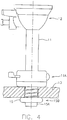
- a trocar support 10 for attachment to a trocar 12 to support a sleeve 11 of the trocar 12 while the sleeve 11 penetrates through a body wall 13 of a patient.
- the support 10 comprises an abutment member 14 shaped to be received on an outer surface of the trocar sleeve.
- the abutment member forms a collar 14A surrounding the sleeve with a manually operable over-center clamp 14B for releasable connection to the sleeve 11 so as to be adjustable longitudinally of the trocar sleeve 11 so as to be located at a selected position 11A as shown in Figure 4 .
- the support 10 includes an inflatable collar 15 for mounting on the trocar sleeve 11 at a required position 15B spaced from the abutment member 14 at the position 11A.
- the inflatable collar can be inflated by a source of fluid, typically air or other gas, from a pump 17 to a predetermined size through a supply tube 16.
- the inflatable collar while deflated can be inserted on the trocar sleeve through an incision in the body wall and can be inflated from the pump 17 through the tube 16 when inserted to the inflated condition shown in Figure 4 at 15B to engage an inside surface of the body wall 13.
- the abutment member can be moved to a position 11A to hold the body wall 13 between the abutment member 14 and the inflatable collar 15.
- the source of fluid provided by the pump 17 is located on the trocar support and particularly the abutment member 14 so as to be carried thereby.
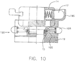
- the pump 17 includes a manually compressible button 17A which extends into a cylinder 17B to drive a measured volume of the fluid to the inflatable collar.
- the button 17A has a latch (not shown) which holds it compressed to keep the inflation until extraction is required whereupon the latch can be released by a further press on the button 17A to allow a spring 17C to expel the button and extract the fluid from the collar 15.
- the source of fluid therefore is a pump mechanism forming a part of the trocar support and operable by hand.
- the source of fluid 17 provides a fixed volume allowing inflation of the collar 15 only to a fixed size.
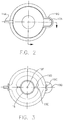
- the tube 16 is of a circular cross-section or in some cases of a flattened cross-section so as to lie flat against the sleeve of the trocar and is wrapped helically around the sleeve of the trocar. Thus it can lie in compressed side by side turns as shown in the initial position in Figure 1 and can extend axially as shown in Figure 9 .
- the inflatable collar 15 includes a sleeve portion 15A extending downwardly from a bottom edge of the collar which can be unrolled on to the trocar sleeve as shown in Figure 4 . In the initial position shown in Figure 1 , the collar and sleeve are rolled up into the structure for later deployment.
- the inflatable collar 15 and the abutment member 14 form a common collar portion 10 which can be engaged onto the trocar sleeve 11 and moved axially therealong from the lower insertion end to a required position along the length of the trocar sleeve.
- a support collar 19 which surrounds the inflatable collar 15 which is attached to the abutment member 14 and moves therewith onto the trocar sleeve.
- the support sleeve includes a collar 19A with a hollow interior 19B forming a shelf 19C carrying the collar 15.
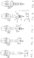
- the support collar 19 is removable axially from the abutment member and the inflatable collar in a direction over the end of the trocar 11 when the inflatable collar 15 reaches its required axial position as shown in Figure 8 .
- the support collar 19 includes a manually operable release member 19C, 19D to release the support collar 10 from the inflatable collar 15. This operates by a lever 19D holding the collar 15 in place until release is required whereupon a manually operable member 19C is operated to release the lever and to allow the collar 15 to unroll and then the collar 19 to move axially away from the collar 15.
- the member 19C can form a cam with lobes 19E which hold the lever 19D in place until the lobes are rotated around a longitudinal axis 19F releasing the levers and allowing the collar 15 to be deployed.
- Lever 19D can be loaded with a spring, which will ensure that the lever pivots away from the inflatable collar when released.
- member 19C can be a manually operable push button, which holds lever 19D in place when pressed once and releases the lever when pressed again. When pressed, the button has a latch, which keeps it compressed. The latch is released by a further press on the button to allow it to be expelled by a spring.
- the support collar 19 is molded from a plastic material so as to be rigid to protect the inflatable collar and includes a protective cover 19G at one side forming a cup for engaging over the manually operable button 17A of the pump 17.
- the abutment member 14 can move axially along the trocar sleeve from the inflatable collar 15 when the latter has reached its required axial location 15B with the tube 16 being extended along the trocar sleeve as the abutment member moves away from the inflatable collar.
- a manually operable device 19S on the support collar 19 operable by a button 19R for operating on the inflatable collar 15 at the required axial location 15B on the trocar to hold the inflatable collar 15 against axial movement at the required location 15B on the trocar sleeve.
- This device 19S can operate using many different techniques as described below, so as to ensure that the collar 15 remains at the required location until the inflation secures it more effectively.
- a circular ferrule, coil or split ring can be swaged into position using swaging tool features built into the device support collar.
- a cam system is used to apply force to metal elements, which transfer that force to the outer diameter of the circular ferrule, coil or split ring causing it to plastically deform securing the inflatable abutment into position.
- a threaded compression fitting system built into the support collar similar to what is shown in Figure 10 , can be used to swage the ferrule, coil or split ring into position.
- the threaded lower portion of the support collar is manually operable by rotating it relative to the threaded upper portion of the support collar causing them to close together and transfer force to outer diameter of the circular ferrule, coil or split ring causing it to plastically deform securing the inflatable abutment into position.
- the device support collar can have an arrangement to hold a spring coil/split ring open until the trocar is inserted into position. The spring coil/split ring is then released applying the spring force to lower collar of the inflatable abutment securing it into position on the trocar sleeve.
- the inner diameter of the elastic collar of the inflatable abutment can have an adhesive surface that is covered until ready for use.
- the removable device support collar has an arrangement to hold the inflatable collar stretched open. Once the adhesive is exposed and the trocar is inserted in position the inflatable collar is released.
- the device support collar can have an arrangement to cinch an embedded fine wire or band attached to the lower collar of the inflatable abutment.
- the upper abutment prefferably has a mechanism for self retracting the excess fluid conduit as the upper abutment is moved towards the lower abutment.
- Another approach is to utilize a self-expanding supply bladder that wraps around part of the trocar (within the upper abutment) and has sufficient volume to fully inflate the lower portion when fully compressed.
- This is a closed system comprising the bladder, fluid conduit and the lower inflatable portion;
- Another option is to use a manual multi-stroke pump with a bleed valve to prevent over-inflation and an indicator to show when the lower portion is fully inflated and fully deflated. The pump is then reversed for deflation;
- the lever mechanism shown on the top of the upper abutment is used to secure the upper abutment in position on the trocar via a collar that tightens around the trocar.
- An alternative is to make this a push button feature for greater ease of use.
- the button is located on the circumference of the upper abutment in the same way that the inflation pump is shown. Depressing the button applies pressure on the wall of the trocar sleeve, thus, holding it in position.
- the device can also be manually installed onto the trocar sleeve by hand without using the support collar.
- the trocar is inserted into the device and the inflatable collar is drawn along the axis of the trocar sleeve and unrolled onto the trocar sleeve by hand at the desired position.
Claims (12)
- Trokarhaltevorrichtung (10), um einen Trokar (12) zu halten, der eine Trokarhülse (11) aufweist, wobei sich die Trokarhülse (11) durch eine Körperwand eines Patienten erstreckt, wobei die Haltevorrichtung (10) ein getrenntes Element umfasst, das zur Anbringung an dem Trokar (12) angeordnet ist und Folgendes umfasst:ein Widerlagerelement (14), das so geformt ist, dass es eine Außenfläche der Trokarhülse (11) aufnimmt, wobeidas Widerlagerelement (14) so angeordnet ist, dass es in Längsrichtung der Trokarhülse (11) eingestellt werden kann, um sich somit an einer ausgewählten Position zu befinden,wenigstens ein aufblasbares Element (15), das sich um die Trokarhülse (11) erstreckt und über eine Fluidquelle (17) auf eine vorgegebene Größe aufgeblasen werden kann, wobeidas wenigstens eine aufblasbare Element (15) so angeordnet ist, dass es an der Trokarhülse (11) in einer Position angebracht werden kann, die auf eine solche Weise von dem Widerlagerelement (14) beabstandet ist, dass das wenigstens eine aufblasbare Element (15) an der Trokarhülse (11) durch einen Schnitt in der Körperwand eingeführt werden kann, während aus dem aufblasbarem Element (15) Luft abgelassen wird, und aufgeblasen werden kann, wenn es eingeführt wird, um in eine Innenfläche der Körperwand einzugreifen, und zwar derart, dass das Widerlagerelement (14) in eine Position bewegt werden kann, in der die Körperwand zwischen dem Widerlagerelement (14) und dem wenigstens einen aufblasbaren Element (15) gehalten ist,wobei die Fluidquelle (17) auf dem Widerlagerelement (14) der Trokarhaltevorrichtung so getragen ist, dass sie von demselben getragen ist.
- Trokarhaltevorrichtung nach Anspruch 1, wobei die Fluidquelle (17) ein von Hand betätigbarer Pumpmechanismus ist.
- Trokarhaltevorrichtung nach Anspruch 1 oder 2, wobei die Fluidquelle (17) ein festes Volumen bereitstellt, das den Aufblasvorgang nur bis zu einer festen Größe ermöglicht.
- Trokarhaltevorrichtung nach einem der vorhergehenden Ansprüche, wobei ein Rohr (16) die Fluidquelle (17) an der Trokarhalterung mit dem wenigstens einen aufblasbaren Element (15) verbindet.
- Trokarhaltevorrichtung nach Anspruch 4, wobei das Rohr (16) spiralförmig um die Hülse (11) des Trokars gewickelt ist.
- Trokarhaltevorrichtung nach Anspruch 4 oder 5, wobei das Rohr (16) einen abgeflachten Querschnitt aufweist, um flach an der Hülse (11) des Trokars anzuliegen.
- Trokarhaltevorrichtung nach einem der vorhergehenden Ansprüche, wobei das wenigstens eine aufblasbare Element (15) einen Hülsenabschnitt (15A) umfasst, der auf die Trokarhülse (11) aufgerollt werden kann.
- Trokarhaltevorrichtung nach einem der vorhergehenden Ansprüche, wobei das wenigstens eine aufblasbare Element (15) und das Widerlagerelement (14) einen gemeinsamen Kragenabschnitt (10) ausbilden, der auf die Trokarhülse (11) in Eingriff gebracht und axial entlang derselben bewegt werden kann.
- Trokarhaltevorrichtung nach Anspruch 8, wobei der gemeinsame Kragenabschnitt (10) anschließend, während der Einsatz erfolgt, in das getrennte aufblasbare Element (15) und das getrennte Widerlagerelement (14) getrennt werden kann.
- Trokarhaltevorrichtung nach einem der vorhergehenden Ansprüche, wobei ein Haltekragen (19A) für das wenigstens eine aufblasbare Element (15) vorgesehen ist, der an dem Widerlagerelement (14) angebracht ist und sich mit demselben auf die Trokarhülse (11) bewegt, und wobei der Haltekragen (19A) von dem Widerlagerelement (14) und dem wenigstens einen aufblasbaren Element (15) abgenommen werden kann, wenn das wenigstens eine aufblasbare Element (15) die erforderliche axiale Position erreicht.
- Trokarhaltevorrichtung nach Anspruch 10, wobei der Haltekragen (19A) ein manuell betätigbares Löseelement (19C) umfasst, um den Haltekragen (19A) von dem wenigstens einen aufblasbaren Element (15) zu lösen.
- Trokarhaltevorrichtung nach einem der vorhergehenden Ansprüche, wobei das Widerlagerelement (14) einen Kragen mit einer manuell betätigbaren Klemme (14B) für den Eingriff mit der Trokarhülse (11) umfasst.
Priority Applications (1)
| Application Number | Priority Date | Filing Date | Title |
|---|---|---|---|
| EP17155777.0A EP3195819B1 (de) | 2011-08-17 | 2012-08-10 | Trokarträger |
Applications Claiming Priority (2)
| Application Number | Priority Date | Filing Date | Title |
|---|---|---|---|
| US201161524470P | 2011-08-17 | 2011-08-17 | |
| PCT/CA2012/050546 WO2013023293A2 (en) | 2011-08-17 | 2012-08-10 | Trocar support |
Related Child Applications (2)
| Application Number | Title | Priority Date | Filing Date |
|---|---|---|---|
| EP17155777.0A Division-Into EP3195819B1 (de) | 2011-08-17 | 2012-08-10 | Trokarträger |
| EP17155777.0A Division EP3195819B1 (de) | 2011-08-17 | 2012-08-10 | Trokarträger |
Publications (3)
| Publication Number | Publication Date |
|---|---|
| EP2744428A2 EP2744428A2 (de) | 2014-06-25 |
| EP2744428A4 EP2744428A4 (de) | 2015-04-01 |
| EP2744428B1 true EP2744428B1 (de) | 2017-05-10 |
Family
ID=47715518
Family Applications (2)
| Application Number | Title | Priority Date | Filing Date |
|---|---|---|---|
| EP12824427.4A Active EP2744428B1 (de) | 2011-08-17 | 2012-08-10 | Trokarträger |
| EP17155777.0A Active EP3195819B1 (de) | 2011-08-17 | 2012-08-10 | Trokarträger |
Family Applications After (1)
| Application Number | Title | Priority Date | Filing Date |
|---|---|---|---|
| EP17155777.0A Active EP3195819B1 (de) | 2011-08-17 | 2012-08-10 | Trokarträger |
Country Status (14)
| Country | Link |
|---|---|
| US (2) | US9681887B2 (de) |
| EP (2) | EP2744428B1 (de) |
| JP (2) | JP6138784B2 (de) |
| KR (1) | KR101996103B1 (de) |
| CN (2) | CN106236206B (de) |
| AU (1) | AU2012297530B2 (de) |
| BR (3) | BR122021000783B1 (de) |
| CA (3) | CA3048514C (de) |
| ES (2) | ES2731359T3 (de) |
| IL (1) | IL230990B (de) |
| MX (3) | MX360745B (de) |
| RU (2) | RU2721297C2 (de) |
| TR (1) | TR201908875T4 (de) |
| WO (1) | WO2013023293A2 (de) |
Families Citing this family (15)
| Publication number | Priority date | Publication date | Assignee | Title |
|---|---|---|---|---|
| KR101996103B1 (ko) * | 2011-08-17 | 2019-07-03 | 서지칼 스테빌라이제이션 테크놀로지스 잉크 | 트로카 지지체 |
| GB2529651B (en) * | 2014-08-27 | 2018-07-11 | Medishield Bv | Detachable anchor for guiding tool of minimally invasive surgery |
| DE112014007031T5 (de) * | 2014-12-31 | 2017-07-20 | Halliburton Energy Services, Inc. | Verbesserung der Geosteering-Inversion unter Verwendung von einem elektromagnetischen Look-Ahead-Look-Around-Werkzeug |
| US9681889B1 (en) * | 2015-06-09 | 2017-06-20 | Surgentec, Llc | Depth controlled needle assembly |
| EP3376976B1 (de) * | 2015-11-17 | 2020-07-15 | Surgical Stabilization Technologies Inc. | Trokarträger |
| US11006941B2 (en) * | 2016-01-29 | 2021-05-18 | Boston Scientific Limited | Access device having an anchoring feature and methods of using the same |
| US10485582B2 (en) | 2016-07-22 | 2019-11-26 | Intuitive Surgical Operations, Inc. | Cannulas having body wall retention features, and related systems and methods |
| KR102055767B1 (ko) * | 2016-11-30 | 2019-12-13 | 배경철 | 트로카 |
| US11357540B2 (en) | 2018-02-16 | 2022-06-14 | Covidien Lp | Port fixation device |
| RU183470U1 (ru) * | 2018-04-11 | 2018-09-24 | Андрей Викторович Сигаев | Устройство для проведения в мочевой пузырь фиксирующихся уретральных катетеров при троакарной цистостомии |
| US11357542B2 (en) | 2019-06-21 | 2022-06-14 | Covidien Lp | Valve assembly and retainer for surgical access assembly |
| CN111938772B (zh) * | 2020-08-17 | 2021-08-06 | 广州保瑞医疗技术有限公司 | 一种用于医用穿刺器包含薄膜管和骨架管的中空管组件 |
| WO2022099137A1 (en) * | 2020-11-09 | 2022-05-12 | ClearCam Inc. | Devices, methods, and apparatuses for mitigating insufflation gas leakage from a trocar |
| RU207999U1 (ru) * | 2021-09-13 | 2021-11-29 | Александр Александрович Соколов | Регулируемый фиксатор для лапароскопических троакаров |
| WO2024062472A1 (en) * | 2022-09-23 | 2024-03-28 | T.A.G. Medical Products Corporation Ltd. | Trocar including cannula |
Family Cites Families (39)
| Publication number | Priority date | Publication date | Assignee | Title |
|---|---|---|---|---|
| US3044468A (en) | 1958-12-01 | 1962-07-17 | Davol Rubber Co | Catheter having built-in inflation means |
| US3253594A (en) | 1963-07-30 | 1966-05-31 | Frank E Matthews | Peritoneal cannula |
| US4861334A (en) | 1988-06-24 | 1989-08-29 | Nawaz Arain | Self-retaining gastrostomy tube |
| US5002557A (en) * | 1989-04-06 | 1991-03-26 | Hasson Harrith M | Laparoscopic cannula |
| US5176697A (en) | 1989-04-06 | 1993-01-05 | Hasson Harrith M | Laparoscopic cannula |
| CA2052310A1 (en) | 1990-10-09 | 1992-04-10 | Thomas L. Foster | Surgical access sheath |
| US5147316A (en) * | 1990-11-19 | 1992-09-15 | Castillenti Thomas A | Laparoscopic trocar with self-locking port sleeve |
| US5728119A (en) | 1991-05-29 | 1998-03-17 | Origin Medsystems, Inc. | Method and inflatable chamber apparatus for separating layers of tissue |
| CA2114644C (en) | 1991-08-01 | 2002-04-30 | Gareth Williams | Preservatives for wood and other cellulosic materials |
| US5338302A (en) | 1993-05-03 | 1994-08-16 | Hasson Harrith M | Vaginal stabilizer cannula |
| US5366478A (en) * | 1993-07-27 | 1994-11-22 | Ethicon, Inc. | Endoscopic surgical sealing device |
| US5697946A (en) * | 1994-10-07 | 1997-12-16 | Origin Medsystems, Inc. | Method and apparatus for anchoring laparoscopic instruments |
| US5957888A (en) * | 1995-10-10 | 1999-09-28 | United States Surgical Corporation | Surgical cannula having a variable length |
| JP2002518140A (ja) | 1998-06-25 | 2002-06-25 | シー・アール・バード・インコーポレーテッド | エラストマーバルブを備える医療装置 |
| RU2221505C2 (ru) * | 2000-06-07 | 2004-01-20 | Ившин Владислав Геннадьевич | Устройство для чрескожного дренирования полостных образований |
| US20040138702A1 (en) | 2001-05-31 | 2004-07-15 | Kenneth Peartree | Balloon cannula with over-center clamp |
| CA2485106A1 (en) * | 2002-05-09 | 2003-11-20 | Tyco Healthcare Group Lp | Adjustable balloon anchoring trocar |
| WO2004032756A2 (en) | 2002-10-04 | 2004-04-22 | Tyco Healthcare Group, Lp | Balloon dissector with cannula |
| US20040111061A1 (en) | 2002-11-12 | 2004-06-10 | Diana Curran | Trocar having an inflatable cuff for maintaining an insufflated abdominal cavity during an open laparaoscopy procedure |
| EP1689282A4 (de) | 2003-10-15 | 2011-08-31 | Tyco Healthcare | Verfahren zur verbindung von materialien |
| RU2269316C1 (ru) * | 2004-09-09 | 2006-02-10 | Кондратьев Александр Владимирович | Эндохирургический обтуратор для инструментов |
| US20060079922A1 (en) | 2004-10-12 | 2006-04-13 | Brian Creston | Balloon anchored surgical apparatus, its use and manufacture |
| US7597688B1 (en) | 2004-12-27 | 2009-10-06 | Masson Marcos V | Cannula apparatus with inflatable seal and adjustable length |
| US8287503B2 (en) * | 2006-03-13 | 2012-10-16 | Applied Medical Resources Corporation | Balloon trocar |
| US8147453B2 (en) | 2006-03-13 | 2012-04-03 | Applied Medical Resources Corporation | Balloon trocar |
| US8066673B2 (en) * | 2006-03-21 | 2011-11-29 | Applied Medical Resources Corporation | Cannula stabilization seal |
| JP5588359B2 (ja) * | 2008-03-03 | 2014-09-10 | アプライド メディカル リソーシーズ コーポレイション | バルーントロカールの新固定方式 |
| US20100010449A1 (en) | 2008-07-09 | 2010-01-14 | Kyphon Sarl | Cannula Stabilization Device, System, And Method Of Use |
| US7998113B2 (en) * | 2008-09-30 | 2011-08-16 | Tyco Healthcare Group Lp | Medical device having prefilled balloon |
| US20100081994A1 (en) | 2008-10-01 | 2010-04-01 | David Leslie Zisow | Self Retaining Laparoscopic Trocar System-Zisow Trocar Sleeve System |
| US8048027B2 (en) * | 2008-12-11 | 2011-11-01 | Tyco Healthcare Group Lp | Trocar entry incorporating an airbag |
| CN201312951Y (zh) * | 2008-12-18 | 2009-09-23 | 苏州大学 | 一种腹腔镜穿刺套管 |
| US8317690B2 (en) * | 2009-03-31 | 2012-11-27 | Covidien Lp | Foam port and introducer assembly |
| CN201572081U (zh) * | 2009-12-23 | 2010-09-08 | 郭秀琪 | 无盲区腹腔镜专用套管 |
| CN201624745U (zh) * | 2010-02-04 | 2010-11-10 | 张士更 | 一种新型腹腔镜穿刺套管 |
| US20110196205A1 (en) * | 2010-02-05 | 2011-08-11 | Tyco Healthcare Group Lp | Surgical portal locking system |
| CN101843518B (zh) * | 2010-06-07 | 2011-10-05 | 常州威克医疗器械有限公司 | 一次性穿刺器 |
| KR101996103B1 (ko) * | 2011-08-17 | 2019-07-03 | 서지칼 스테빌라이제이션 테크놀로지스 잉크 | 트로카 지지체 |
| US8888692B1 (en) | 2011-08-26 | 2014-11-18 | Applied Medical Resources Corporation | Trocar cannula assembly and method of manufacture |
-
2012
- 2012-08-10 KR KR1020147006772A patent/KR101996103B1/ko active IP Right Grant
- 2012-08-10 BR BR122021000783-7A patent/BR122021000783B1/pt active IP Right Grant
- 2012-08-10 BR BR112014003660-8A patent/BR112014003660B1/pt active IP Right Grant
- 2012-08-10 AU AU2012297530A patent/AU2012297530B2/en active Active
- 2012-08-10 RU RU2017101659A patent/RU2721297C2/ru active
- 2012-08-10 JP JP2014525269A patent/JP6138784B2/ja active Active
- 2012-08-10 MX MX2017011891A patent/MX360745B/es unknown
- 2012-08-10 CA CA3048514A patent/CA3048514C/en active Active
- 2012-08-10 CA CA2845401A patent/CA2845401C/en active Active
- 2012-08-10 EP EP12824427.4A patent/EP2744428B1/de active Active
- 2012-08-10 MX MX2014001868A patent/MX353204B/es active IP Right Grant
- 2012-08-10 US US14/239,006 patent/US9681887B2/en active Active
- 2012-08-10 BR BR122021000786-1A patent/BR122021000786B1/pt active IP Right Grant
- 2012-08-10 ES ES17155777T patent/ES2731359T3/es active Active
- 2012-08-10 RU RU2014110051A patent/RU2608628C2/ru active
- 2012-08-10 TR TR2019/08875T patent/TR201908875T4/tr unknown
- 2012-08-10 CN CN201610710940.9A patent/CN106236206B/zh active Active
- 2012-08-10 EP EP17155777.0A patent/EP3195819B1/de active Active
- 2012-08-10 ES ES12824427.4T patent/ES2636775T3/es active Active
- 2012-08-10 MX MX2018009883A patent/MX364014B/es unknown
- 2012-08-10 WO PCT/CA2012/050546 patent/WO2013023293A2/en active Application Filing
- 2012-08-10 CN CN201280040150.4A patent/CN103917179B/zh active Active
- 2012-08-10 CA CA3011997A patent/CA3011997C/en active Active
-
2014
- 2014-02-16 IL IL230990A patent/IL230990B/en active IP Right Grant
-
2017
- 2017-02-28 JP JP2017037761A patent/JP6399566B2/ja active Active
- 2017-04-20 US US15/492,696 patent/US10166043B2/en active Active
Also Published As
Similar Documents
| Publication | Publication Date | Title |
|---|---|---|
| EP2744428B1 (de) | Trokarträger | |
| AU2020277246B2 (en) | Trocar support | |
| EP1392178A1 (de) | Chirurgischer retraktor |
Legal Events
| Date | Code | Title | Description |
|---|---|---|---|
| PUAI | Public reference made under article 153(3) epc to a published international application that has entered the european phase |
Free format text: ORIGINAL CODE: 0009012 |
|
| 17P | Request for examination filed |
Effective date: 20140317 |
|
| AK | Designated contracting states |
Kind code of ref document: A2 Designated state(s): AL AT BE BG CH CY CZ DE DK EE ES FI FR GB GR HR HU IE IS IT LI LT LU LV MC MK MT NL NO PL PT RO RS SE SI SK SM TR |
|
| A4 | Supplementary search report drawn up and despatched |
Effective date: 20150226 |
|
| RIC1 | Information provided on ipc code assigned before grant |
Ipc: A61B 17/34 20060101AFI20150220BHEP |
|
| RAP1 | Party data changed (applicant data changed or rights of an application transferred) |
Owner name: SURGICAL STABILIZATION TECHNOLOGIES INC. |
|
| RIN1 | Information on inventor provided before grant (corrected) |
Inventor name: SURGICAL STABILIZATION TECHNOLOGIES INC. |
|
| 17Q | First examination report despatched |
Effective date: 20160203 |
|
| GRAP | Despatch of communication of intention to grant a patent |
Free format text: ORIGINAL CODE: EPIDOSNIGR1 |
|
| STAA | Information on the status of an ep patent application or granted ep patent |
Free format text: STATUS: GRANT OF PATENT IS INTENDED |
|
| INTG | Intention to grant announced |
Effective date: 20161207 |
|
| RIN1 | Information on inventor provided before grant (corrected) |
Inventor name: CORBETT, CAROLINE ALISON Inventor name: PACAK, JOHN STEPHEN Inventor name: DIAMOND, HAETHER DAWN |
|
| GRAS | Grant fee paid |
Free format text: ORIGINAL CODE: EPIDOSNIGR3 |
|
| GRAA | (expected) grant |
Free format text: ORIGINAL CODE: 0009210 |
|
| STAA | Information on the status of an ep patent application or granted ep patent |
Free format text: STATUS: THE PATENT HAS BEEN GRANTED |
|
| RAP1 | Party data changed (applicant data changed or rights of an application transferred) |
Owner name: SURGICAL STABILIZATION TECHNOLOGIES INC. |
|
| AK | Designated contracting states |
Kind code of ref document: B1 Designated state(s): AL AT BE BG CH CY CZ DE DK EE ES FI FR GB GR HR HU IE IS IT LI LT LU LV MC MK MT NL NO PL PT RO RS SE SI SK SM TR |
|
| REG | Reference to a national code |
Ref country code: GB Ref legal event code: FG4D |
|
| REG | Reference to a national code |
Ref country code: AT Ref legal event code: REF Ref document number: 891475 Country of ref document: AT Kind code of ref document: T Effective date: 20170515 Ref country code: CH Ref legal event code: EP |
|
| REG | Reference to a national code |
Ref country code: IE Ref legal event code: FG4D |
|
| REG | Reference to a national code |
Ref country code: DE Ref legal event code: R096 Ref document number: 602012032359 Country of ref document: DE |
|
| REG | Reference to a national code |
Ref country code: NL Ref legal event code: FP |
|
| REG | Reference to a national code |
Ref country code: FR Ref legal event code: PLFP Year of fee payment: 6 |
|
| REG | Reference to a national code |
Ref country code: SE Ref legal event code: TRGR |
|
| REG | Reference to a national code |
Ref country code: LT Ref legal event code: MG4D |
|
| REG | Reference to a national code |
Ref country code: ES Ref legal event code: FG2A Ref document number: 2636775 Country of ref document: ES Kind code of ref document: T3 Effective date: 20171009 |
|
| REG | Reference to a national code |
Ref country code: AT Ref legal event code: MK05 Ref document number: 891475 Country of ref document: AT Kind code of ref document: T Effective date: 20170510 |
|
| PG25 | Lapsed in a contracting state [announced via postgrant information from national office to epo] |
Ref country code: AT Free format text: LAPSE BECAUSE OF FAILURE TO SUBMIT A TRANSLATION OF THE DESCRIPTION OR TO PAY THE FEE WITHIN THE PRESCRIBED TIME-LIMIT Effective date: 20170510 Ref country code: NO Free format text: LAPSE BECAUSE OF FAILURE TO SUBMIT A TRANSLATION OF THE DESCRIPTION OR TO PAY THE FEE WITHIN THE PRESCRIBED TIME-LIMIT Effective date: 20170810 Ref country code: LT Free format text: LAPSE BECAUSE OF FAILURE TO SUBMIT A TRANSLATION OF THE DESCRIPTION OR TO PAY THE FEE WITHIN THE PRESCRIBED TIME-LIMIT Effective date: 20170510 Ref country code: FI Free format text: LAPSE BECAUSE OF FAILURE TO SUBMIT A TRANSLATION OF THE DESCRIPTION OR TO PAY THE FEE WITHIN THE PRESCRIBED TIME-LIMIT Effective date: 20170510 Ref country code: GR Free format text: LAPSE BECAUSE OF FAILURE TO SUBMIT A TRANSLATION OF THE DESCRIPTION OR TO PAY THE FEE WITHIN THE PRESCRIBED TIME-LIMIT Effective date: 20170811 Ref country code: HR Free format text: LAPSE BECAUSE OF FAILURE TO SUBMIT A TRANSLATION OF THE DESCRIPTION OR TO PAY THE FEE WITHIN THE PRESCRIBED TIME-LIMIT Effective date: 20170510 |
|
| PG25 | Lapsed in a contracting state [announced via postgrant information from national office to epo] |
Ref country code: LV Free format text: LAPSE BECAUSE OF FAILURE TO SUBMIT A TRANSLATION OF THE DESCRIPTION OR TO PAY THE FEE WITHIN THE PRESCRIBED TIME-LIMIT Effective date: 20170510 Ref country code: IS Free format text: LAPSE BECAUSE OF FAILURE TO SUBMIT A TRANSLATION OF THE DESCRIPTION OR TO PAY THE FEE WITHIN THE PRESCRIBED TIME-LIMIT Effective date: 20170910 Ref country code: RS Free format text: LAPSE BECAUSE OF FAILURE TO SUBMIT A TRANSLATION OF THE DESCRIPTION OR TO PAY THE FEE WITHIN THE PRESCRIBED TIME-LIMIT Effective date: 20170510 Ref country code: PL Free format text: LAPSE BECAUSE OF FAILURE TO SUBMIT A TRANSLATION OF THE DESCRIPTION OR TO PAY THE FEE WITHIN THE PRESCRIBED TIME-LIMIT Effective date: 20170510 Ref country code: BG Free format text: LAPSE BECAUSE OF FAILURE TO SUBMIT A TRANSLATION OF THE DESCRIPTION OR TO PAY THE FEE WITHIN THE PRESCRIBED TIME-LIMIT Effective date: 20170810 |
|
| PG25 | Lapsed in a contracting state [announced via postgrant information from national office to epo] |
Ref country code: CZ Free format text: LAPSE BECAUSE OF FAILURE TO SUBMIT A TRANSLATION OF THE DESCRIPTION OR TO PAY THE FEE WITHIN THE PRESCRIBED TIME-LIMIT Effective date: 20170510 Ref country code: EE Free format text: LAPSE BECAUSE OF FAILURE TO SUBMIT A TRANSLATION OF THE DESCRIPTION OR TO PAY THE FEE WITHIN THE PRESCRIBED TIME-LIMIT Effective date: 20170510 Ref country code: RO Free format text: LAPSE BECAUSE OF FAILURE TO SUBMIT A TRANSLATION OF THE DESCRIPTION OR TO PAY THE FEE WITHIN THE PRESCRIBED TIME-LIMIT Effective date: 20170510 Ref country code: DK Free format text: LAPSE BECAUSE OF FAILURE TO SUBMIT A TRANSLATION OF THE DESCRIPTION OR TO PAY THE FEE WITHIN THE PRESCRIBED TIME-LIMIT Effective date: 20170510 Ref country code: SK Free format text: LAPSE BECAUSE OF FAILURE TO SUBMIT A TRANSLATION OF THE DESCRIPTION OR TO PAY THE FEE WITHIN THE PRESCRIBED TIME-LIMIT Effective date: 20170510 |
|
| REG | Reference to a national code |
Ref country code: DE Ref legal event code: R097 Ref document number: 602012032359 Country of ref document: DE |
|
| PG25 | Lapsed in a contracting state [announced via postgrant information from national office to epo] |
Ref country code: SM Free format text: LAPSE BECAUSE OF FAILURE TO SUBMIT A TRANSLATION OF THE DESCRIPTION OR TO PAY THE FEE WITHIN THE PRESCRIBED TIME-LIMIT Effective date: 20170510 |
|
| PLBE | No opposition filed within time limit |
Free format text: ORIGINAL CODE: 0009261 |
|
| STAA | Information on the status of an ep patent application or granted ep patent |
Free format text: STATUS: NO OPPOSITION FILED WITHIN TIME LIMIT |
|
| PG25 | Lapsed in a contracting state [announced via postgrant information from national office to epo] |
Ref country code: MC Free format text: LAPSE BECAUSE OF FAILURE TO SUBMIT A TRANSLATION OF THE DESCRIPTION OR TO PAY THE FEE WITHIN THE PRESCRIBED TIME-LIMIT Effective date: 20170510 |
|
| 26N | No opposition filed |
Effective date: 20180213 |
|
| PG25 | Lapsed in a contracting state [announced via postgrant information from national office to epo] |
Ref country code: SI Free format text: LAPSE BECAUSE OF FAILURE TO SUBMIT A TRANSLATION OF THE DESCRIPTION OR TO PAY THE FEE WITHIN THE PRESCRIBED TIME-LIMIT Effective date: 20170510 |
|
| REG | Reference to a national code |
Ref country code: BE Ref legal event code: MM Effective date: 20170831 |
|
| PG25 | Lapsed in a contracting state [announced via postgrant information from national office to epo] |
Ref country code: LU Free format text: LAPSE BECAUSE OF NON-PAYMENT OF DUE FEES Effective date: 20170810 |
|
| REG | Reference to a national code |
Ref country code: FR Ref legal event code: PLFP Year of fee payment: 7 |
|
| PG25 | Lapsed in a contracting state [announced via postgrant information from national office to epo] |
Ref country code: BE Free format text: LAPSE BECAUSE OF NON-PAYMENT OF DUE FEES Effective date: 20170831 |
|
| PG25 | Lapsed in a contracting state [announced via postgrant information from national office to epo] |
Ref country code: MT Free format text: LAPSE BECAUSE OF NON-PAYMENT OF DUE FEES Effective date: 20170810 |
|
| PG25 | Lapsed in a contracting state [announced via postgrant information from national office to epo] |
Ref country code: HU Free format text: LAPSE BECAUSE OF FAILURE TO SUBMIT A TRANSLATION OF THE DESCRIPTION OR TO PAY THE FEE WITHIN THE PRESCRIBED TIME-LIMIT; INVALID AB INITIO Effective date: 20120810 |
|
| PG25 | Lapsed in a contracting state [announced via postgrant information from national office to epo] |
Ref country code: CY Free format text: LAPSE BECAUSE OF NON-PAYMENT OF DUE FEES Effective date: 20170510 |
|
| PG25 | Lapsed in a contracting state [announced via postgrant information from national office to epo] |
Ref country code: MK Free format text: LAPSE BECAUSE OF FAILURE TO SUBMIT A TRANSLATION OF THE DESCRIPTION OR TO PAY THE FEE WITHIN THE PRESCRIBED TIME-LIMIT Effective date: 20170510 |
|
| PG25 | Lapsed in a contracting state [announced via postgrant information from national office to epo] |
Ref country code: PT Free format text: LAPSE BECAUSE OF FAILURE TO SUBMIT A TRANSLATION OF THE DESCRIPTION OR TO PAY THE FEE WITHIN THE PRESCRIBED TIME-LIMIT Effective date: 20170510 |
|
| PG25 | Lapsed in a contracting state [announced via postgrant information from national office to epo] |
Ref country code: AL Free format text: LAPSE BECAUSE OF FAILURE TO SUBMIT A TRANSLATION OF THE DESCRIPTION OR TO PAY THE FEE WITHIN THE PRESCRIBED TIME-LIMIT Effective date: 20170510 |
|
| PGFP | Annual fee paid to national office [announced via postgrant information from national office to epo] |
Ref country code: TR Payment date: 20220929 Year of fee payment: 11 Ref country code: SE Payment date: 20220929 Year of fee payment: 11 Ref country code: NL Payment date: 20220929 Year of fee payment: 11 Ref country code: IE Payment date: 20220929 Year of fee payment: 11 Ref country code: GB Payment date: 20220929 Year of fee payment: 11 Ref country code: DE Payment date: 20220929 Year of fee payment: 11 |
|
| PGFP | Annual fee paid to national office [announced via postgrant information from national office to epo] |
Ref country code: FR Payment date: 20220930 Year of fee payment: 11 |
|
| PGFP | Annual fee paid to national office [announced via postgrant information from national office to epo] |
Ref country code: IT Payment date: 20220929 Year of fee payment: 11 Ref country code: ES Payment date: 20221024 Year of fee payment: 11 |
|
| PGFP | Annual fee paid to national office [announced via postgrant information from national office to epo] |
Ref country code: CH Payment date: 20221024 Year of fee payment: 11 |
|
| PGFP | Annual fee paid to national office [announced via postgrant information from national office to epo] |
Ref country code: NL Payment date: 20240219 Year of fee payment: 12 Ref country code: IE Payment date: 20240219 Year of fee payment: 12 Ref country code: ES Payment date: 20240223 Year of fee payment: 12 |