EP2741590A1 - Halterungsvorrichtung für ein in der Höhe verstellbares funktionales Elemente - Google Patents
Halterungsvorrichtung für ein in der Höhe verstellbares funktionales Elemente Download PDFInfo
- Publication number
- EP2741590A1 EP2741590A1 EP12195686.6A EP12195686A EP2741590A1 EP 2741590 A1 EP2741590 A1 EP 2741590A1 EP 12195686 A EP12195686 A EP 12195686A EP 2741590 A1 EP2741590 A1 EP 2741590A1
- Authority
- EP
- European Patent Office
- Prior art keywords
- flexor
- region
- functional element
- height
- adjustable
- Prior art date
- Legal status (The legal status is an assumption and is not a legal conclusion. Google has not performed a legal analysis and makes no representation as to the accuracy of the status listed.)
- Granted
Links
- 230000001419 dependent effect Effects 0.000 claims description 3
- 239000002245 particle Substances 0.000 description 7
- XEEYBQQBJWHFJM-UHFFFAOYSA-N Iron Chemical compound [Fe] XEEYBQQBJWHFJM-UHFFFAOYSA-N 0.000 description 2
- 238000004873 anchoring Methods 0.000 description 2
- 230000007246 mechanism Effects 0.000 description 2
- 238000004801 process automation Methods 0.000 description 2
- 230000004044 response Effects 0.000 description 2
- 230000005469 synchrotron radiation Effects 0.000 description 2
- 230000001133 acceleration Effects 0.000 description 1
- 238000005452 bending Methods 0.000 description 1
- 230000008859 change Effects 0.000 description 1
- 238000010276 construction Methods 0.000 description 1
- 230000005670 electromagnetic radiation Effects 0.000 description 1
- 230000004907 flux Effects 0.000 description 1
- 229910052742 iron Inorganic materials 0.000 description 1
- 239000002184 metal Substances 0.000 description 1
- 229910052751 metal Inorganic materials 0.000 description 1
- 238000000034 method Methods 0.000 description 1
- 238000005457 optimization Methods 0.000 description 1
- 230000000737 periodic effect Effects 0.000 description 1
- 230000008569 process Effects 0.000 description 1
- 230000005855 radiation Effects 0.000 description 1
- 230000002441 reversible effect Effects 0.000 description 1
Images
Classifications
-
- H—ELECTRICITY
- H05—ELECTRIC TECHNIQUES NOT OTHERWISE PROVIDED FOR
- H05H—PLASMA TECHNIQUE; PRODUCTION OF ACCELERATED ELECTRICALLY-CHARGED PARTICLES OR OF NEUTRONS; PRODUCTION OR ACCELERATION OF NEUTRAL MOLECULAR OR ATOMIC BEAMS
- H05H7/00—Details of devices of the types covered by groups H05H9/00, H05H11/00, H05H13/00
- H05H7/04—Magnet systems, e.g. undulators, wigglers; Energisation thereof
-
- H—ELECTRICITY
- H05—ELECTRIC TECHNIQUES NOT OTHERWISE PROVIDED FOR
- H05H—PLASMA TECHNIQUE; PRODUCTION OF ACCELERATED ELECTRICALLY-CHARGED PARTICLES OR OF NEUTRONS; PRODUCTION OR ACCELERATION OF NEUTRAL MOLECULAR OR ATOMIC BEAMS
- H05H7/00—Details of devices of the types covered by groups H05H9/00, H05H11/00, H05H13/00
- H05H7/04—Magnet systems, e.g. undulators, wigglers; Energisation thereof
- H05H2007/041—Magnet systems, e.g. undulators, wigglers; Energisation thereof for beam bunching, e.g. undulators
Definitions
- the present invention relates to a support device for a height-adjustable functional element.
- the present invention relates to magnet / pole pairs used in undulators.
- a wiggler or undulator is a linear series of dipole magnets connected in series in alternating north-south orientation. If a particle is deflected by a magnetic field, for example, this means physically that it experiences an acceleration. A light electrically charged particle (electron or positron) then emits electromagnetic radiation, which, if the particle moves at approximately the speed of light, is called synchrotron radiation.
- the present invention is therefore based on the object of specifying a mounting device for a height-adjustable functional elements, which keeps the position provided during the adjustment exactly and which allows a comparatively quick adjustment.
- the mounting device allows to adjust the functional element in height, without the functional element would have to be removed for its adjustment or solved on the support element.
- the support element for adjusting the functional element does not have to be solved in its anchoring in the base support. Only in the selectable position of the pressure element determines the pressure on the flexor area and thus its evasion response to the pressure.
- the flexor area is of course dimensioned so that this contact pressure is always greater than the oppositely acting magnetic force.
- the pressure element can be designed as a wedge and cooperate with an arranged on the underside of the flexor region inclined plane, wherein the height adjustment is achieved by a movement of the wedge relative to the inclined plane.
- the wedge may be arranged, for example, on a screw-push rod, the screwing relative to the inclined plane makes the desired pressure and thus the desired height adjustment achievable.
- the pressure element can also be designed as an eccentric and cooperate with the underside of the flexor area, wherein the height adjustment is achieved by a rotation of the eccentric relative to the underside of the flexor area. Again, only a rotation of the eccentric and a subsequent fixing of the eccentric in the desired position required to achieve the desired height adjustment.
- the flexor region can be delimited from the base region by at least one lamellar-shaped region.
- the pressure is then achieved by the adjustable in the base area and fixable pressure element on the flexor area, wherein the deformation then occurs in the lamellar shaped area that raises or lowers the flexor relative to the base area.
- the holding device is preferably used in an undulator, wherein the functional element is then a magnet / pole pair of an undulator.
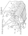
- the drawing shows a perspective view of a holding device 2 for magnet / pole pairs 4, which are provided for use in an ondulator not shown here.
- the mounting device 2 mounting device comprises a base support 6 with a receiving device 8 for at least one support member 10 for the magnet / pole pair 4.
- the receiving device 8 is designed as a plug-in strip, which by means of a Screw fixable sheet metal allows the fixed support of the support members 10 in the base support 6.
- the carrier element 10 is configured as an extruded profile and has a base region 12 and a height-adjustable flexor region 14 arranged above the base region 12 and height-adjustable in the direction of an arrow 16, on which the magnet / pole pair 4 is fastened.
- an adjustable pressure element configured as a wedge 18 is provided in the base area 12, which exerts a height-dependent mechanical pressure in the direction of the arrow 16 on the flexor area 14 depending on the selected position.
- the pressure element designed as a wedge 18 interacts with an inclined plane 20 arranged on the underside of the flexor region 14, wherein the height adjustment can be achieved by moving the wedge 18 relative to the inclined plane 20 in the direction of an arrow 22.
- the wedge 14 is held screwed in the base area and can achieve a further increase in the flexor area 14, for example, by a movement in the left side of the drawing.
- the wedge 18 is flat against the inclined plane 20, so that rotation is excluded and a perfect height adjustment of the magnet / pole pair 4 is achieved.
- the screw mechanism for adjusting the position of the wedge 18 can also be designed to be driven in an automated manner. An adjustment of the height of the magnet / pole pair 4 would then also be possible automatically by the mechanism could be driven by remote control via a process automation.
- process automation devices are freely available on the market, for example, from the companies Siemens Aktiengesellschaft (product family SIMATIC®) or ABB Aktiengesellschaft.
- the pressure element could also be designed as an eccentric and interact with the underside of the flexor area, wherein the height adjustment by rotation of the eccentric relative to the underside of the flexor area 14 could be achieved.
- the flexor region 14 is delimited from the base region 12 by four lamellar-shaped thin regions 24. These thin regions 24 may deform by reversible bending, thus allowing yielding (at the lift) and sinking (at the dip) of the flexor region 14.
- the mounting device 2 makes it possible to adjust the magnet / pole pair 4 in height, without the magnet / pole pair 4 would have to be removed for its adjustment or solved on the support member 10.
- the carrier element 10 for adjusting the magnet / pole pair 4 need not be solved in its anchoring in the base support 6. Only in the selectable position of the pressure element (wedge 14 or not shown eccentric) determines the pressure on the flexor area 14 and thus its evasion response to the pressure in the direction of arrow 16.
Landscapes
- Physics & Mathematics (AREA)
- Optics & Photonics (AREA)
- Engineering & Computer Science (AREA)
- Plasma & Fusion (AREA)
- Spectroscopy & Molecular Physics (AREA)
- Particle Accelerators (AREA)
Abstract
Description
- Die vorliegende Erfindung bezieht sich auf eine Halterungsvorrichtung für ein in der Höhe verstellbares funktionales Elemente. Dabei bezieht sich die vorliegende Erfindung im Besonderen auf in Undulatoren eingesetzte Magnet/Pol-Paare.
- Bei einem Wiggler oder Undulator handelt es sich um eine lineare Folge von Dipolmagneten, die in abwechselnder Nord-Süd-Ausrichtung hintereinander geschaltet sind. Wird ein Teilchen etwa durch ein Magnetfeld abgelenkt, so bedeutet dies physikalisch gleichzeitig, dass es eine Beschleunigung erfährt. Ein leichtes elektrisch geladenes Teilchen (Elektron oder Positron) gibt dann elektromagnetische Strahlung ab, die man, sofern das Teilchen sich annähernd mit Lichtgeschwindigkeit bewegt, als Synchrotronstrahlung bezeichnet.
- Durch die spezielle Magnetanordnung in einem Wiggler oder Undulator wird ein durch sie hindurchfliegendes Teilchen auf eine periodische, meist sinusförmige Bahn gezwungen. Das so beschleunigte Teilchen erzeugt nun Synchrotronstrahlung in seiner durchschnittlichen Flugrichtung. Die Eigenschaften der erzeugten Strahlung hängen stark von der Länge der einzelnen Magnete, der Stärke des Magnetfeldes und der Geschwindigkeit, Ladung und Masse des Teilchens ab.
- Es gibt eine Reihe unterschiedlicher Bauarten für Wiggler und Undulatoren:
- Elektromagnetische Bauweise, bei der entweder ein gemeinsames Eisenjoch von verschiedenen normalleitenden Spulen umschlossen wird (magnetische Flussdichte B = 2 Tesla (Einheitenzeichen: T)), oder supraleitende Stromspulen schalenförmig angeordnet werden (B > 2 T bis etwa 12 T), so dass sie das alternierende Dipolfeld bilden
- Permanentmagneten (B = 0,8-1,0 T)
- Hybrid-Magneten, hier werden die Magnetfelder mehrerer Permanentmagnete durch ein metallisches Joch geführt, man erreicht dadurch eine höhere Feldstärke als mit Permanentmagneten allein. (B>2 T)
- Zur Einstellung und Justierung der genauen Flugbahn der geladenen Teilchen ist es erforderlich, dass die Magnet in ihrer Anordnung justierbar angeordnet sein muss. Eine Optimierung des Magnetfeldes wird daher heute durch das Tauschen von Magneten oder durch Schimmen (Unterlegen von Plättchen unterschiedlicher Höhe) erzielt. Neuerdings werden anstelle des Schimmens auch mit einer Schraube verstellbare Keile eingesetzt, wobei wie beim Schimmen eine Fixierung des Magneten zuvor gelöst und anschliessend wieder angezogen werden muss, was allerdings wieder zu einer ungewollten minimalen Positionsveränderung führen kann. Weiter ist es bei diesen Lösungen nachteilig, dass allein zur Justierung eines einzelnen Magneten ein erheblicher Zeitaufwand erforderlich ist. In Synchroton-Anlage der Anmelderin kann dieser Vorgang leicht bis zu mehreren Wochen in Anspruch nehmen.
- Der vorliegenden Erfindung liegt daher die Aufgabe zugrunde, eine Halterungsvorrichtung für ein in der Höhe verstellbares funktionales Elemente anzugeben, welches die bei der Justierung vorgesehene Position exakt hält und die eine vergleichsweise schnelle Justierung ermöglicht.
- Diese Aufgabe wird erfindungsgemäss dadurch gelöst, dass eine Halterungsvorrichtung für ein in der Höhe verstellbares funktionales Elemente vorgesehen ist, umfassend:
- einen Grundträger mit einer Aufnahmevorrichtung für mindestens ein Trägerelement für das funktionale Element,
- wobei das Trägerelement einen Sockelbereich und einen oberhalb des Sockelbereichs angeordneten in der Höhe verstellbaren Flexor-Bereich aufweist, auf dem das funktionale Element befestigbar aufsitzt, und wobei der Sockelbereich ein verstellbares Andruckelement aufweist, das eine zur Höhenverstellung einen von der gewählten Stellung abhängigen mechanischen Druck auf den Flexor-Bereich ausübt.
- Auf diese Weise ermöglicht es die Halterungsvorrichtung, das funktionale Element in der Höhe verstellen zu können, ohne dass das funktionale Element zu seiner Justierung entfernt oder am Trägerelement gelöst werden müsste. Ebenso muss auch das Trägerelement zur Justierung des funktionalen Elements nicht in seiner Verankerung im Grundträger gelöst werden. Einzigallein die wählbare Position des Andruckelements bestimmt den Andruck an den Flexor-Bereich und damit dessen Ausweichreaktion auf den Andruck. Der Flexorbereich ist dabei selbstverständlich so dimensioniert, dass dieser Andruck immer grösser ist, als die entgegengesetzt wirkende Magnetkraft.
- In einer besonders vorteilhaften Ausgestaltung der vorliegenden Erfindung kann das Andruckelement als Keil ausgestaltet sein und mit einer auf der Unterseite des Flexor-Bereichs angeordneten schiefen Ebene zusammenwirken, wobei die Höhenverstellung durch eine Bewegung des Keils relativ zur schiefen Ebene erzielbar ist. Hierzu kann der Keil beispielsweise auf einer schraubbaren Schubstange angeordnet sein, deren Verschraubung relativ zur schiefen Ebene den gewünschten Andruck und damit die gewünschte Höhenverstellung erzielbar macht.
- In einer hierzu alternativen Ausgestaltung der vorliegenden Erfindung kann das Andruckelement auch als Excenter ausgestaltet sein und mit der Unterseite des Flexor-Bereichs zusammenwirken, wobei die Höhenverstellung durch eine Verdrehung des Excenters relativ zur Unterseite des Flexor-Bereichs erzielbar ist. Auch hier sind nur eine Verdrehung des Exzenters und eine anschliessende Festsetzung des Exzenters in der gewünschten Position erforderlich, um die gewünschte Höhenverstellung zu erzielen.
- In einer bevorzugten Ausgestaltung für das Trägerelement kann das Flexorbereich durch mindestens einen lamellenartig geformten Bereich von dem Sockelbereich abgegrenzt sein. Der Andruck wird dann von dem im Sockelbereich verstell- und festsetzbaren Andruckelement auf den Flexor-Bereich erzielt, wobei die Verformung dann im lamellenartig geformten Bereich auftritt, die den Flexorbereich relativ zum Sockelbereich anhebt oder absenkt.
- Wie eingangs erwähnt, wird die Halterungsvorrichtung vorzugsweise in einem Undulator eingesetzt, wobei das funktionale Element dann ein Magnet/Pol-Paar eines Undulators ist.
- Bevorzugte Ausführungsbeispiele der vorliegenden Erfindung werden anhand einer Zeichnung näher erläutert. Die Zeichnung zeigt dabei eine perspektivische Ansicht auf eine Halterungsvorrichtung 2 für Magnet/Pol-Paare 4, die zum Einsatz in einem hier nicht weiter dargestellten Ondulator vorgesehen sind. Die Halterungsvorrichtung 2 Halterungsvorrichtung umfasst einen Grundträger 6 mit einer Aufnahmevorrichtung 8 für mindestens ein Trägerelement 10 für das Magnet/Pol-Paar 4. Die Aufnahmevorrichtung 8 ist dabei als Einschubleiste ausgestaltet, die mittels eines mit Schrauben festsetzbaren Bleches die feste Halterung der Trägerelemente 10 in dem Grundträger 6 ermöglicht.
- Das Trägerelement 10 ist als Strangpressprofil ausgestaltet und weist einen Sockelbereich 12 und einen oberhalb des Sockelbereichs 12 angeordneten in der Höhe in Richtung eines Pfeils 16 höhenverstellbaren Flexor-Bereich 14 aufweist, auf dem das Magnet/Pol-Paar 4 befestigt ist. Zur Höhenverstellung des Flexor-Bereichs 14 ist im Sockelbereich 12 ein als Keil 18 ausgestaltetes verstellbares Andruckelement vorgesehen, das zur Höhenverstellung einen von der gewählten Stellung abhängigen mechanischen Druck in Richtung des Pfeils 16 auf den Flexorbereich 14 ausübt. Das als Keil 18 ausgestaltet Andruckelement wirkt mit einer auf der Unterseite des Flexor-Bereichs 14 angeordneten schiefen Ebene 20 zusammenwirkt, wobei die Höhenverstellung durch eine Bewegung des Keils 18 relativ zur schiefen Ebene 20 in Richtung eines Pfeils 22 erzielbar ist. Hierzu ist der Keil 14 im Sockelbereich verschraubbar gehalten und kann beispielsweise durch eine Bewegung in der zeichnerischen Darstellung linke Seite eine weitere Anhebung des Flexor-Bereichs 14 erzielen. Dabei liegt der Keil 18 flächig an der schiefen Ebene 20 an, sodass ein Verdrehen ausgeschlossen und eine tadellose Höhenverstellung des Magnet/Pol-Paares 4 erzielt ist. In einer hier nicht weiter dargestellten Ausführungsform kann der Schraubmechanismus zur Verstellung der Position des Keils 18 auch automatisiert antreibbar ausgestaltet sein. Eine Justierung der Höhe des Magnet/Pol-Paares 4 wäre dann auch automatisch möglich, indem der Mechanismus über eine Prozessautomatisierung ferngesteuert angetrieben werden könnte. Derartige Prozessautomatisierungseinrichtungen sind beispielsweise von den Firmen Siemens Aktiengesellschaft (Produktfamilie SIMATIC®) oder ABB Aktiengesellschaft frei am Markt erhältlich.
- In hier nicht weiter dargestellter alternativer Bauweise könnte das Andruckelement auch als Excenter ausgestaltet sein und mit der Unterseite des Flexor-Bereichs zusammenwirken, wobei die Höhenverstellung durch eine Verdrehung des Excenters relativ zur Unterseite des Flexor-Bereichs 14 erzielbar wäre.
- Der Flexorbereich 14 wird im vorliegenden Ausführungsbeispiel durch vier lamellenartig geformte dünne Bereiche 24 von dem Sockelbereich 12 abgegrenzt. Diese dünnen Bereiche 24 können sich durch reversible Verbiegung verformen und ermöglichen so ein Nachgeben (bei der Anhebung) sowie ein Absinken (bei der Absenkung) des Flexor-Bereichs 14.
- Auf diese Weise ermöglicht es die Halterungsvorrichtung 2, das Magnet/Pol-Paar 4 in der Höhe verstellen zu können, ohne dass das Magnet/Pol-Paar 4 zu seiner Justierung entfernt oder am Trägerelement 10 gelöst werden müsste. Ebenso muss auch das Trägerelement 10 zur Justierung des Magnet/Pol-Paares 4 nicht in seiner Verankerung im Grundträger 6 gelöst werden. Einzigallein die wählbare Position des Andruckelements (Keil 14 oder nicht dargestellter Exzenter) bestimmt den Andruck an den Flexor-Bereich 14 und damit dessen Ausweichreaktion auf den Andruck in Richtung des Pfeils 16.
Claims (5)
- Halterungsvorrichtung (2) für ein in der Höhe verstellbares funktionales Element (4), umfassend:einen Grundträger (6) mit einer Aufnahmevorrichtung (8) für mindestens ein Trägerelement (10) für das funktionale Element (4), wobei das Trägerelement (10) einen Sockelbereich (12) und einen oberhalb des Sockelbereichs (12) angeordneten in der Höhe verstellbaren Flexor-Bereich (24) aufweist, auf dem das funktionale Element (4) befestigbar aufsitzt, und wobei der Sockelbereich (12) ein verstellbares Andruckelement (18) aufweist, das zur Höhenverstellung einen von der gewählten Stellung abhängigen mechanischen Druck auf den Flexorbereich (24) ausübt.
- Halterungsvorrichtung (2) nach Anspruch 1,
dadurch gekennzeichnet, dass
das Andruckelement als Keil (24) ausgestaltet ist und mit einer auf der Unterseite des Flexor-Bereichs angeordneten schiefen Ebene (20) zusammenwirkt, wobei die Höhenverstellung durch eine Bewegung des Keils (18) relativ zur schiefen Ebene (20) erzielbar ist. - Halterungsvorrichtung nach Anspruch 1,
dadurch gekennzeichnet, dass
das Andruckelement als Excenter ausgestaltet ist und mit der Unterseite des Flexor-Bereichs zusammenwirkt, wobei die Höhenverstellung durch eine Verdrehung des Excenters relativ zur Unterseite des Flexor-Bereichs erzielbar ist. - Halterungsvorrichtung (2) nach einem der Ansprüche 1 bis 3, dadurch gekennzeichnet, dass
das Flexorbereich (14) durch mindestens einen lamellenartig geformten Bereich (24) von dem Sockelbereich (12) abgegrenzt ist. - Halterungsvorrichtung nach einem der vorangehenden Ansprüche, dadurch gekennzeichnet, dass
das funktionale Element ein Magnet/Pol-Paar eines Undulators ist.
Priority Applications (1)
| Application Number | Priority Date | Filing Date | Title |
|---|---|---|---|
| EP12195686.6A EP2741590B1 (de) | 2012-12-05 | 2012-12-05 | Halterungsvorrichtung für ein in der Höhe verstellbares funktionales Elemente |
Applications Claiming Priority (1)
| Application Number | Priority Date | Filing Date | Title |
|---|---|---|---|
| EP12195686.6A EP2741590B1 (de) | 2012-12-05 | 2012-12-05 | Halterungsvorrichtung für ein in der Höhe verstellbares funktionales Elemente |
Publications (2)
| Publication Number | Publication Date |
|---|---|
| EP2741590A1 true EP2741590A1 (de) | 2014-06-11 |
| EP2741590B1 EP2741590B1 (de) | 2019-03-06 |
Family
ID=47471529
Family Applications (1)
| Application Number | Title | Priority Date | Filing Date |
|---|---|---|---|
| EP12195686.6A Not-in-force EP2741590B1 (de) | 2012-12-05 | 2012-12-05 | Halterungsvorrichtung für ein in der Höhe verstellbares funktionales Elemente |
Country Status (1)
| Country | Link |
|---|---|
| EP (1) | EP2741590B1 (de) |
Citations (2)
| Publication number | Priority date | Publication date | Assignee | Title |
|---|---|---|---|---|
| US5383049A (en) * | 1993-02-10 | 1995-01-17 | The Board Of Trustees Of Leland Stanford University | Elliptically polarizing adjustable phase insertion device |
| US7956557B1 (en) * | 2007-09-11 | 2011-06-07 | Advanced Design Consulting Usa, Inc. | Support structures for planar insertion devices |
-
2012
- 2012-12-05 EP EP12195686.6A patent/EP2741590B1/de not_active Not-in-force
Patent Citations (2)
| Publication number | Priority date | Publication date | Assignee | Title |
|---|---|---|---|---|
| US5383049A (en) * | 1993-02-10 | 1995-01-17 | The Board Of Trustees Of Leland Stanford University | Elliptically polarizing adjustable phase insertion device |
| US7956557B1 (en) * | 2007-09-11 | 2011-06-07 | Advanced Design Consulting Usa, Inc. | Support structures for planar insertion devices |
Non-Patent Citations (2)
| Title |
|---|
| I.VASSERMAN ET AL: "LCLS Undulator Design Development", PROCEEDINGS OF THE 2004 FEL CONFERENCE, TRIESTE, ITALY, September 2004 (2004-09-01), pages 367 - 370, XP002695829 * |
| J.COLLINS ET AL: "Magnets, Supports and Controls for the Linac Coherent Light Source (LCLS) Undulator System", PROCEEDINGS OF FEL08, GYEONGJU, KOREA, June 2009 (2009-06-01), pages 452 - 454, XP002695830 * |
Also Published As
| Publication number | Publication date |
|---|---|
| EP2741590B1 (de) | 2019-03-06 |
Similar Documents
| Publication | Publication Date | Title |
|---|---|---|
| EP3582376B1 (de) | Beförderungsvorrichtung mit sicherheitsfunktion | |
| DE1122588B (de) | Elektromagnetischer Vielfachschalter fuer Fernmelde-, insbesondere Fernsprechanlagen | |
| DE2730985C2 (de) | Bestrahlungsvorrichtung unter Verwendung geladener Teilchen | |
| DE3423482C1 (de) | Permanentmagnetische Lastgreif - oder Halteeinrichtung | |
| EP2741590B1 (de) | Halterungsvorrichtung für ein in der Höhe verstellbares funktionales Elemente | |
| DE731121C (de) | Kontaktfedergruppe | |
| EP2732540A2 (de) | Motor | |
| DE202013001284U1 (de) | Gerätekombination zum Löten und Entlöten oberflächenmontierter Komponenten auf einer Leiterplatte | |
| EP3973622A1 (de) | Zweiachspositioniervorrichtung | |
| EP0110133B1 (de) | Elektromagnetisches Relais | |
| DE3508768C2 (de) | ||
| DE2445438A1 (de) | Elektromagnetisches antriebselement fuer den schreibkopf eines punktmatrixschreibers sowie fuer eine verwendung des antriebselementes geeigneter schreibkopf | |
| DE702957C (de) | Elektromagnetischer Selbstunterbrecher | |
| WO2005006371A1 (de) | Elektromagnetisches schaltgerät | |
| EP1647657B1 (de) | Schiebetür mit einer magnetischen Trageeinrichtung mit Tragkraftverstellung | |
| DE3127939A1 (de) | Waage mit flachem magnet | |
| WO2024240645A1 (de) | Vorrichtung zum befestigen zumindest einer sensoreinrichtung an einer schiene einer bahngleisanlage | |
| DE887540C (de) | Elektromagnetisches Relais mit permanentem Hilfsmagneten | |
| DE102009048461B3 (de) | Motorantrieb mit einer Einrichtung zur sicheren Montage mit einem Leistungsschalter | |
| DE102017207791A1 (de) | Halteeinrichtung für Werkstücke und Umrüststation | |
| DE102004050342B4 (de) | Schiebetür mit einem kombinierten magnetischen Trag- und Antriebssystem mit einer Magnetreihe | |
| EP0051231A1 (de) | Haltemagnetauslöser | |
| DE589147C (de) | Relais fuer mehrbegriffiges Lichtsignal | |
| DE202012010786U1 (de) | Salamander | |
| DE2433678C3 (de) | Abtastelement zum Abtasten von Zielkennzeichenmagneten |
Legal Events
| Date | Code | Title | Description |
|---|---|---|---|
| PUAI | Public reference made under article 153(3) epc to a published international application that has entered the european phase |
Free format text: ORIGINAL CODE: 0009012 |
|
| 17P | Request for examination filed |
Effective date: 20121205 |
|
| AK | Designated contracting states |
Kind code of ref document: A1 Designated state(s): AL AT BE BG CH CY CZ DE DK EE ES FI FR GB GR HR HU IE IS IT LI LT LU LV MC MK MT NL NO PL PT RO RS SE SI SK SM TR |
|
| AX | Request for extension of the european patent |
Extension state: BA ME |
|
| R17P | Request for examination filed (corrected) |
Effective date: 20141106 |
|
| RBV | Designated contracting states (corrected) |
Designated state(s): AL AT BE BG CH CY CZ DE DK EE ES FI FR GB GR HR HU IE IS IT LI LT LU LV MC MK MT NL NO PL PT RO RS SE SI SK SM TR |
|
| GRAP | Despatch of communication of intention to grant a patent |
Free format text: ORIGINAL CODE: EPIDOSNIGR1 |
|
| STAA | Information on the status of an ep patent application or granted ep patent |
Free format text: STATUS: GRANT OF PATENT IS INTENDED |
|
| INTG | Intention to grant announced |
Effective date: 20181120 |
|
| GRAS | Grant fee paid |
Free format text: ORIGINAL CODE: EPIDOSNIGR3 |
|
| GRAA | (expected) grant |
Free format text: ORIGINAL CODE: 0009210 |
|
| STAA | Information on the status of an ep patent application or granted ep patent |
Free format text: STATUS: THE PATENT HAS BEEN GRANTED |
|
| AK | Designated contracting states |
Kind code of ref document: B1 Designated state(s): AL AT BE BG CH CY CZ DE DK EE ES FI FR GB GR HR HU IE IS IT LI LT LU LV MC MK MT NL NO PL PT RO RS SE SI SK SM TR |
|
| REG | Reference to a national code |
Ref country code: GB Ref legal event code: FG4D Free format text: NOT ENGLISH |
|
| REG | Reference to a national code |
Ref country code: CH Ref legal event code: EP Ref country code: AT Ref legal event code: REF Ref document number: 1106386 Country of ref document: AT Kind code of ref document: T Effective date: 20190315 |
|
| REG | Reference to a national code |
Ref country code: DE Ref legal event code: R096 Ref document number: 502012014380 Country of ref document: DE |
|
| REG | Reference to a national code |
Ref country code: IE Ref legal event code: FG4D Free format text: LANGUAGE OF EP DOCUMENT: GERMAN |
|
| REG | Reference to a national code |
Ref country code: NL Ref legal event code: MP Effective date: 20190306 |
|
| REG | Reference to a national code |
Ref country code: LT Ref legal event code: MG4D |
|
| PG25 | Lapsed in a contracting state [announced via postgrant information from national office to epo] |
Ref country code: LT Free format text: LAPSE BECAUSE OF FAILURE TO SUBMIT A TRANSLATION OF THE DESCRIPTION OR TO PAY THE FEE WITHIN THE PRESCRIBED TIME-LIMIT Effective date: 20190306 Ref country code: SE Free format text: LAPSE BECAUSE OF FAILURE TO SUBMIT A TRANSLATION OF THE DESCRIPTION OR TO PAY THE FEE WITHIN THE PRESCRIBED TIME-LIMIT Effective date: 20190306 Ref country code: NO Free format text: LAPSE BECAUSE OF FAILURE TO SUBMIT A TRANSLATION OF THE DESCRIPTION OR TO PAY THE FEE WITHIN THE PRESCRIBED TIME-LIMIT Effective date: 20190606 Ref country code: FI Free format text: LAPSE BECAUSE OF FAILURE TO SUBMIT A TRANSLATION OF THE DESCRIPTION OR TO PAY THE FEE WITHIN THE PRESCRIBED TIME-LIMIT Effective date: 20190306 |
|
| PG25 | Lapsed in a contracting state [announced via postgrant information from national office to epo] |
Ref country code: GR Free format text: LAPSE BECAUSE OF FAILURE TO SUBMIT A TRANSLATION OF THE DESCRIPTION OR TO PAY THE FEE WITHIN THE PRESCRIBED TIME-LIMIT Effective date: 20190607 Ref country code: NL Free format text: LAPSE BECAUSE OF FAILURE TO SUBMIT A TRANSLATION OF THE DESCRIPTION OR TO PAY THE FEE WITHIN THE PRESCRIBED TIME-LIMIT Effective date: 20190306 Ref country code: RS Free format text: LAPSE BECAUSE OF FAILURE TO SUBMIT A TRANSLATION OF THE DESCRIPTION OR TO PAY THE FEE WITHIN THE PRESCRIBED TIME-LIMIT Effective date: 20190306 Ref country code: BG Free format text: LAPSE BECAUSE OF FAILURE TO SUBMIT A TRANSLATION OF THE DESCRIPTION OR TO PAY THE FEE WITHIN THE PRESCRIBED TIME-LIMIT Effective date: 20190606 Ref country code: LV Free format text: LAPSE BECAUSE OF FAILURE TO SUBMIT A TRANSLATION OF THE DESCRIPTION OR TO PAY THE FEE WITHIN THE PRESCRIBED TIME-LIMIT Effective date: 20190306 Ref country code: HR Free format text: LAPSE BECAUSE OF FAILURE TO SUBMIT A TRANSLATION OF THE DESCRIPTION OR TO PAY THE FEE WITHIN THE PRESCRIBED TIME-LIMIT Effective date: 20190306 |
|
| PG25 | Lapsed in a contracting state [announced via postgrant information from national office to epo] |
Ref country code: EE Free format text: LAPSE BECAUSE OF FAILURE TO SUBMIT A TRANSLATION OF THE DESCRIPTION OR TO PAY THE FEE WITHIN THE PRESCRIBED TIME-LIMIT Effective date: 20190306 Ref country code: IT Free format text: LAPSE BECAUSE OF FAILURE TO SUBMIT A TRANSLATION OF THE DESCRIPTION OR TO PAY THE FEE WITHIN THE PRESCRIBED TIME-LIMIT Effective date: 20190306 Ref country code: SK Free format text: LAPSE BECAUSE OF FAILURE TO SUBMIT A TRANSLATION OF THE DESCRIPTION OR TO PAY THE FEE WITHIN THE PRESCRIBED TIME-LIMIT Effective date: 20190306 Ref country code: PT Free format text: LAPSE BECAUSE OF FAILURE TO SUBMIT A TRANSLATION OF THE DESCRIPTION OR TO PAY THE FEE WITHIN THE PRESCRIBED TIME-LIMIT Effective date: 20190706 Ref country code: ES Free format text: LAPSE BECAUSE OF FAILURE TO SUBMIT A TRANSLATION OF THE DESCRIPTION OR TO PAY THE FEE WITHIN THE PRESCRIBED TIME-LIMIT Effective date: 20190306 Ref country code: AL Free format text: LAPSE BECAUSE OF FAILURE TO SUBMIT A TRANSLATION OF THE DESCRIPTION OR TO PAY THE FEE WITHIN THE PRESCRIBED TIME-LIMIT Effective date: 20190306 Ref country code: CZ Free format text: LAPSE BECAUSE OF FAILURE TO SUBMIT A TRANSLATION OF THE DESCRIPTION OR TO PAY THE FEE WITHIN THE PRESCRIBED TIME-LIMIT Effective date: 20190306 Ref country code: RO Free format text: LAPSE BECAUSE OF FAILURE TO SUBMIT A TRANSLATION OF THE DESCRIPTION OR TO PAY THE FEE WITHIN THE PRESCRIBED TIME-LIMIT Effective date: 20190306 |
|
| PG25 | Lapsed in a contracting state [announced via postgrant information from national office to epo] |
Ref country code: SM Free format text: LAPSE BECAUSE OF FAILURE TO SUBMIT A TRANSLATION OF THE DESCRIPTION OR TO PAY THE FEE WITHIN THE PRESCRIBED TIME-LIMIT Effective date: 20190306 Ref country code: PL Free format text: LAPSE BECAUSE OF FAILURE TO SUBMIT A TRANSLATION OF THE DESCRIPTION OR TO PAY THE FEE WITHIN THE PRESCRIBED TIME-LIMIT Effective date: 20190306 |
|
| REG | Reference to a national code |
Ref country code: DE Ref legal event code: R097 Ref document number: 502012014380 Country of ref document: DE |
|
| PG25 | Lapsed in a contracting state [announced via postgrant information from national office to epo] |
Ref country code: IS Free format text: LAPSE BECAUSE OF FAILURE TO SUBMIT A TRANSLATION OF THE DESCRIPTION OR TO PAY THE FEE WITHIN THE PRESCRIBED TIME-LIMIT Effective date: 20190706 |
|
| PLBE | No opposition filed within time limit |
Free format text: ORIGINAL CODE: 0009261 |
|
| STAA | Information on the status of an ep patent application or granted ep patent |
Free format text: STATUS: NO OPPOSITION FILED WITHIN TIME LIMIT |
|
| PG25 | Lapsed in a contracting state [announced via postgrant information from national office to epo] |
Ref country code: DK Free format text: LAPSE BECAUSE OF FAILURE TO SUBMIT A TRANSLATION OF THE DESCRIPTION OR TO PAY THE FEE WITHIN THE PRESCRIBED TIME-LIMIT Effective date: 20190306 |
|
| 26N | No opposition filed |
Effective date: 20191209 |
|
| PG25 | Lapsed in a contracting state [announced via postgrant information from national office to epo] |
Ref country code: SI Free format text: LAPSE BECAUSE OF FAILURE TO SUBMIT A TRANSLATION OF THE DESCRIPTION OR TO PAY THE FEE WITHIN THE PRESCRIBED TIME-LIMIT Effective date: 20190306 |
|
| PG25 | Lapsed in a contracting state [announced via postgrant information from national office to epo] |
Ref country code: TR Free format text: LAPSE BECAUSE OF FAILURE TO SUBMIT A TRANSLATION OF THE DESCRIPTION OR TO PAY THE FEE WITHIN THE PRESCRIBED TIME-LIMIT Effective date: 20190306 |
|
| REG | Reference to a national code |
Ref country code: DE Ref legal event code: R119 Ref document number: 502012014380 Country of ref document: DE |
|
| REG | Reference to a national code |
Ref country code: CH Ref legal event code: PL |
|
| REG | Reference to a national code |
Ref country code: BE Ref legal event code: MM Effective date: 20191231 |
|
| PG25 | Lapsed in a contracting state [announced via postgrant information from national office to epo] |
Ref country code: MC Free format text: LAPSE BECAUSE OF FAILURE TO SUBMIT A TRANSLATION OF THE DESCRIPTION OR TO PAY THE FEE WITHIN THE PRESCRIBED TIME-LIMIT Effective date: 20190306 |
|
| GBPC | Gb: european patent ceased through non-payment of renewal fee |
Effective date: 20191205 |
|
| PG25 | Lapsed in a contracting state [announced via postgrant information from national office to epo] |
Ref country code: DE Free format text: LAPSE BECAUSE OF NON-PAYMENT OF DUE FEES Effective date: 20200701 Ref country code: GB Free format text: LAPSE BECAUSE OF NON-PAYMENT OF DUE FEES Effective date: 20191205 Ref country code: IE Free format text: LAPSE BECAUSE OF NON-PAYMENT OF DUE FEES Effective date: 20191205 Ref country code: FR Free format text: LAPSE BECAUSE OF NON-PAYMENT OF DUE FEES Effective date: 20191231 Ref country code: LU Free format text: LAPSE BECAUSE OF NON-PAYMENT OF DUE FEES Effective date: 20191205 |
|
| PG25 | Lapsed in a contracting state [announced via postgrant information from national office to epo] |
Ref country code: LI Free format text: LAPSE BECAUSE OF NON-PAYMENT OF DUE FEES Effective date: 20191231 Ref country code: CH Free format text: LAPSE BECAUSE OF NON-PAYMENT OF DUE FEES Effective date: 20191231 Ref country code: BE Free format text: LAPSE BECAUSE OF NON-PAYMENT OF DUE FEES Effective date: 20191231 |
|
| REG | Reference to a national code |
Ref country code: AT Ref legal event code: MM01 Ref document number: 1106386 Country of ref document: AT Kind code of ref document: T Effective date: 20191205 |
|
| PG25 | Lapsed in a contracting state [announced via postgrant information from national office to epo] |
Ref country code: CY Free format text: LAPSE BECAUSE OF FAILURE TO SUBMIT A TRANSLATION OF THE DESCRIPTION OR TO PAY THE FEE WITHIN THE PRESCRIBED TIME-LIMIT Effective date: 20190306 Ref country code: AT Free format text: LAPSE BECAUSE OF NON-PAYMENT OF DUE FEES Effective date: 20191205 |
|
| PG25 | Lapsed in a contracting state [announced via postgrant information from national office to epo] |
Ref country code: MT Free format text: LAPSE BECAUSE OF FAILURE TO SUBMIT A TRANSLATION OF THE DESCRIPTION OR TO PAY THE FEE WITHIN THE PRESCRIBED TIME-LIMIT Effective date: 20190306 Ref country code: HU Free format text: LAPSE BECAUSE OF FAILURE TO SUBMIT A TRANSLATION OF THE DESCRIPTION OR TO PAY THE FEE WITHIN THE PRESCRIBED TIME-LIMIT; INVALID AB INITIO Effective date: 20121205 |
|
| PG25 | Lapsed in a contracting state [announced via postgrant information from national office to epo] |
Ref country code: MK Free format text: LAPSE BECAUSE OF FAILURE TO SUBMIT A TRANSLATION OF THE DESCRIPTION OR TO PAY THE FEE WITHIN THE PRESCRIBED TIME-LIMIT Effective date: 20190306 |