EP2741014A2 - Cooking device with lowering door and height-adjustable guide piece - Google Patents
Cooking device with lowering door and height-adjustable guide piece Download PDFInfo
- Publication number
- EP2741014A2 EP2741014A2 EP13194660.0A EP13194660A EP2741014A2 EP 2741014 A2 EP2741014 A2 EP 2741014A2 EP 13194660 A EP13194660 A EP 13194660A EP 2741014 A2 EP2741014 A2 EP 2741014A2
- Authority
- EP
- European Patent Office
- Prior art keywords
- cooking appliance
- door
- boundary wall
- height
- coupled
- Prior art date
- Legal status (The legal status is an assumption and is not a legal conclusion. Google has not performed a legal analysis and makes no representation as to the accuracy of the status listed.)
- Granted
Links
- 238000010411 cooking Methods 0.000 title claims abstract description 64
- 230000008878 coupling Effects 0.000 claims description 35
- 238000010168 coupling process Methods 0.000 claims description 35
- 238000005859 coupling reaction Methods 0.000 claims description 35
- 238000006073 displacement reaction Methods 0.000 claims description 5
- 229910000831 Steel Inorganic materials 0.000 claims description 2
- 239000010959 steel Substances 0.000 claims description 2
- 230000008859 change Effects 0.000 description 8
- 230000008901 benefit Effects 0.000 description 4
- 229910000639 Spring steel Inorganic materials 0.000 description 2
- 230000000694 effects Effects 0.000 description 2
- 230000003993 interaction Effects 0.000 description 2
- 230000007246 mechanism Effects 0.000 description 2
- 206010003830 Automatism Diseases 0.000 description 1
- 230000004308 accommodation Effects 0.000 description 1
- 230000009471 action Effects 0.000 description 1
- 238000005553 drilling Methods 0.000 description 1
- 238000002955 isolation Methods 0.000 description 1
- 238000002360 preparation method Methods 0.000 description 1
Images


Classifications
-
- F—MECHANICAL ENGINEERING; LIGHTING; HEATING; WEAPONS; BLASTING
- F24—HEATING; RANGES; VENTILATING
- F24C—DOMESTIC STOVES OR RANGES ; DETAILS OF DOMESTIC STOVES OR RANGES, OF GENERAL APPLICATION
- F24C15/00—Details
- F24C15/02—Doors specially adapted for stoves or ranges
- F24C15/026—Doors specially adapted for stoves or ranges stowing of door in open position
-
- F—MECHANICAL ENGINEERING; LIGHTING; HEATING; WEAPONS; BLASTING
- F24—HEATING; RANGES; VENTILATING
- F24C—DOMESTIC STOVES OR RANGES ; DETAILS OF DOMESTIC STOVES OR RANGES, OF GENERAL APPLICATION
- F24C15/00—Details
- F24C15/02—Doors specially adapted for stoves or ranges
- F24C15/023—Mounting of doors, e.g. hinges, counterbalancing
Definitions
- the invention relates to a cooking appliance with a housing and a cooking chamber which can be closed by a door.
- the cooking device comprises a guide device, which has at least one guide slot, with which the door is coupled and with which the door is retractable when moving in the open state into a receiving space in the housing.
- Cooking appliances such as an oven or a microwave cooking appliance or a steam cooker, for example, are known from the prior art and have cooking chambers in which foodstuffs can be introduced for preparation. Such a cooking chamber is usually closed at the front by a door.
- a door is arranged on a housing and can only be pivoted about a horizontal or a vertical axis in order to open or close the door.
- cooking appliances have, for example, front vertical shutters arranged laterally to such a door on the housing, which are positioned, for example, as design applications.
- the vertical edge sides of this door usually have a certain gap to these front panels. Due to component tolerances, this gap is not the same at all points and over the entire extension. It may be provided that these front panels can be moved slightly in their position in order to then perform the appropriate gap dimension adjustment to the door. However, this is with regard to Attachment of these front panels difficult, on the other hand limits the gap setting.
- An inventive cooking appliance comprises a housing and a cooking chamber which can be closed by a door.
- the cooking appliance furthermore has a guide device, which comprises at least one guide slot with which the door is coupled and with which the door can be retracted into a housing in the housing when moved to the open state.
- a guide device which comprises at least one guide slot with which the door is coupled and with which the door can be retracted into a housing in the housing when moved to the open state.
- the guide device is designed for height adjustment and thus to Justange the altitude of the door relative to the housing. It is thus created in a cooking appliance with a retractable door now also the opportunity to perform a position adjustment of the door.
- the guide device is designed multifunctional, since it is designed on the one hand to guide the door when sinking and retracting, on the other hand also this position change and in particular allows the height adjustment of the door in the closed state.
- the guide slot is designed as a height adjustment device for the door at least in its closed state. Since just in this position state of the door front side, the gap dimensions to adjacent front panels represent, it is of particular importance to be able to adjust these gaps exactly and maintain.
- a lower boundary wall of the guide slot is at least partially adjustable in height for height adjustment of the door.
- the guide slot is thus viewed in the vertical direction at least downwardly bounded by a boundary wall on which then optionally also a moving means, such as a roller or a ball bearing or the like can hang up and slide along when the door is moved relative to the housing.
- a moving means such as a roller or a ball bearing or the like can hang up and slide along when the door is moved relative to the housing.
- this boundary wall is thus essential and very direct influencing factor on the respective position of the door. It is therefore of particular advantage if just this component is not rigidly seated on the housing, but at least partially movable relative thereto, so that in mechanical interaction with the door an immediate change in altitude occurs.
- this boundary wall as such is also mechanically stable, so that it can ensure wear and height adjustment reliably and permanently wear.
- the boundary wall at the front end in the altitude is adjustable.
- This embodiment is to be particularly emphasized, since just sitting in the closed state of the door of this movement means the door at the front end of the boundary wall or seated on this and thus just then at this point by the mobility and height change a very direct and accurate position change can be achieved , Moreover, in this embodiment, it is no longer necessary for the middle or rear sections of the boundary wall to be movable, so that they can be made rigid. On the one hand, this also improves the mechanical stability of the entire boundary wall and achieves the positionally accurate connection to housing parts.
- the boundary wall is formed in the front region by a vertically movable insert.
- a vertically movable insert As a result, the advantages mentioned above can once again be favored and also optimized individually to the respective requirements. Because different cooking appliances can with regard to design regarding the size and weight and the component assembly be designed variable, so that here also different weights can act on such a boundary wall and in particular the movable part. By such a separate insert, which thus forms a portion of the lower boundary wall, it can be responded to individually, so that even here highest mechanical stresses and precise height adjustments can be accommodated.
- the insert is designed as a strip and in particular made of steel, for example spring steel. This specification is preferred in terms of the above advantages.
- an actuating device for the boundary wall is formed, which is movable with at least one actuating element relative to the boundary wall and can be coupled with this for height adjustment.
- a mechanical design is provided which acts as a separate component on the boundary wall in its movable section in order to effect its height adjustment.
- the actuating element is arranged below the boundary wall.
- the actuating device has a slide element which has a coupling wedge as the actuating element.
- the coupling wedge comprises an inclined contact surface, which is contacted with a contact surface on an underside of the lower boundary wall.
- this contact surface is bevelled on the underside of the lower boundary wall, so that when exposed to the Actuating element on these movable part of the boundary wall a jerk-free sliding along the contact surfaces is achieved together.
- the coupling wedge is tapered at its front end and thus designed to taper at the end facing the front end of the boundary wall.
- the slider element is horizontally displaceable and by sliding along the contact surface of the slider element on the contact surface of the boundary wall, this boundary wall is changeable in the altitude.
- the change in altitude is thus perpendicular to this horizontal movement, so that the relevant directions of movement are perpendicular to each other.
- the slide element on its side facing away from the boundary wall bottom has a latching device which is designed to lock the position of the Schieberlements for latching with a counter-latching.
- This embodiment is advantageous in that a set position of the boundary wall can be permanently maintained because locked by the locking of the slider element and this on a housing component and thus can not be moved undesirable. Just when the slide element is arranged under the movable part of the boundary wall, then results in a very functional interacting action principle of the components.
- the slider element is pressed into the counter-locking by the pushing on the slider element from above boundary wall.
- the position locking of the slider element is favored.
- the height-adjustable part of the lower boundary wall in its normal position and thus in a non-upward raised adjustment position is preferably already mechanically contacted with the actuating element, so that no undesirable down pressing the boundary wall can be done.
- the actuating element Starting from this basic position and the movement of the actuating element then only a situation is reached in which this movable part of the boundary wall is adjusted in height and pushed upwards, so that just then then from this movable part of the boundary wall acting down and on the slider element pressing force is larger, so that this pressing mechanism is increased from the movable part to the slider element.
- the slider element is coupled to an eccentric, and by pressing the eccentric, the slider element is horizontally displaceable.
- the slide element can be locked in its displaced position with a securing element, in particular a securing screw.
- a securing element in particular a securing screw.
- two slide elements are each formed with at least one coupling wedge as actuating elements, which are coupled to each other in such a way that a second horizontal wedge in a second horizontal wedge direction perpendicular to the height direction moves into a further, perpendicular to the height direction and the first horizontal direction stationary second horizontal direction is movable and thereby the altitude of the boundary wall is adjustable.
- actuating elements which are coupled to each other in such a way that a second horizontal wedge in a second horizontal wedge direction perpendicular to the height direction moves into a further, perpendicular to the height direction and the first horizontal direction stationary second horizontal direction is movable and thereby the altitude of the boundary wall is adjustable.
- the second coupling wedge is guided by a guide element in the second horizontal direction.
- a guide element in the second horizontal direction.
- a corresponding bore can be provided here as a guide element.
- two slide elements are each formed with at least one coupling wedge as actuating elements which are coupled to one another so that a first horizontal direction of the second coupling wedge perpendicular to the height direction can be adjusted in the height direction during a movement of the first coupling wedge and thereby the altitude of the boundary wall is adjustable.
- tapered portions of the coupling wedges of the at least two slide elements abut each other and are movable relative to each other. This is also the very continuous and smooth movement is achieved, so that the altitude adjustment is very precise.
- the first slider element is biased in the direction of the first horizontal direction by a spring. This can be achieved in the return to the initial state of an automatism.
- the slide element in extension of the horizontal displacement direction of the slide element, is coupled to an adjusting element, in particular an adjusting screw, wherein the adjusting element is coupled in a front end of the slide element with this.
- an adjusting element in particular an adjusting screw, wherein the adjusting element is coupled in a front end of the slide element with this.
- a provision may be provided by a spring or an insert.
- an actuating element of the actuating device designed as a slide element can be moved exclusively in the vertical direction and, for this purpose, an inclined contact surface on an underside of the slide element is coupled to a contact surface of the guide device. It is provided that an adjustable in a first horizontal direction adjustment moves the slider element in this first horizontal direction and By the coupled contact surfaces at the same time an adjustment in the height direction is possible.
- the actuating element is an eccentric, which rests directly on an underside of the boundary wall and a height adjustment of the boundary wall is adjustable by a movement of the eccentric in a horizontal direction.
- the guide device is designed for at least on one side of the door feasible altitude adjustment and is designed for adjusting the door to a side of the door to the housing arranged front panel.
- the guide device is coupled to the door on two opposite sides in lower corner regions of the door, in particular via two separate guide slots, and is adapted to its adjustment of the altitude, the adjustment of the altitude on one side regardless of the adjustment the other side is feasible.
- tilting of the door can also take place, so that gap dimensions can be set to adjacent vertical diaphragms.
- Fig. 1 is shown in a front view of a trained as an oven cooking device 1.
- the cooking appliance 1 comprises a cooking chamber 2, can be introduced into the food for cooking.
- the cooking chamber 2 is through walls of a muffle 7 ( Fig.2 ), which has a feed opening at the front, which can be closed by a door 3.
- Fig. 1 the closed state of the door 3 is shown, so that it is virtually in the figure plane and thus in the xy plane.
- the cooking appliance 1 also comprises a housing 4, in which the muffle 7 is arranged with the cooking chamber 2.
- Front panels 5 and 6 are arranged adjacent to the door 3 on the housing 4 at the front and to the side.
- the front panels 5 and 6 are strip-like elements that extend at least over the entire height (extension in the y-direction) and thus in the vertical direction of the door 3. They are fastened to the housing 4, for example via fasteners, such as plastic components.
- the position of these front panels 5 and 6 is always relatively accurate compared to the position of the door 3.
- the door 3 is not a hinged door as such, but retractable into the housing 4 inside.
- a receiving space 8 is formed under this muffle 7, in which the door 3, starting from the in Fig. 1 shown closed state when opening is algebrakbar.
- the cooking device 1 comprises a guide device 9.
- the guide device 9 is formed on the opposite vertical walls of the housing 4, respectively, so that the door 3 is correspondingly guided by movement on both opposite sides.
- the guide device 9 comprises a guide slot 10, in which in particular a not shown ball bearing of the door 3 is guided.
- the guide slot 10 comprises an upper boundary wall 11 and a lower boundary wall 12. In addition, a lateral boundary wall 13 is also provided.
- the ball bearing of the door 3 sits quasi on the lower boundary wall 12.
- the guide slot 10 in particular the lower boundary wall 12, is movable in sections and thus in the vertical position (y-direction) is changeable.
- the guide device 9 is formed for height adjustment of the door 3.
- the guide slot 10 is designed as a height adjustment device for the door 3.
- the lower boundary wall 12 is at least partially adjustable in height to the height position of the door 3.
- a front portion 15 of the lower boundary wall 12 is arranged correspondingly relatively movable.
- a separate component in the form of an insert which is in particular made of spring steel, forms this section 15.
- the insert in the form of portion 15 thus also forms the front end of the lower boundary wall 12, wherein the portion 15 to a front end 16 has, which then also forms the front end 14 of the guide slot 10.
- the section 15 is strip-shaped and is in turn at least partially configured non-rectilinear and has a downwardly curved portion 17 on.
- Fig. 3 is a perspective view of an area of the guide device 9 analogous to the representation in Fig. 2 shown.
- the insert is shown in the form of the portion 15, which is fastened, for example via rivet connections on a support 18, which may be formed, for example, of plastic.
- the section 15 is mechanically coupled to an actuator 19.
- the actuating device 19 is arranged below the section 15 in the vertical direction and thus viewed in the y-direction.
- the actuator 19 is already on an underside 20 of the portion 15 of the lower boundary wall 12 at.
- the actuating device 19 comprises a slide element 21, which has a coupling wedge 22 with an inclined contact surface 23 at a front end, which faces the front end 14 of the guide slot 10 and thus also the end 16 of the section 15.
- the inclined contact surface 23 is preferably on an underside 24 of the section 15. In particular, this takes place in the region of the curved region 17 of the section 15.
- the actuating element designed as a slide element 21 is in the embodiment only in a second horizontal direction, namely in the z-direction and thus in the direction of the extension of the guide slot 10 relative to the section 15 of the lower Sliding wall 12 slidable.
- an eccentric 25 is provided. If the eccentric 25 is actuated, then a horizontal displacement of the slider element 21 takes place in said second horizontal direction (z-direction), whereby, as shown in FIG Fig. 5 the insert is raised in the form of the section 15 and thus its position in the height and thus in the y-direction relative to the carrier 18 and thus also relative to the upper boundary wall 11 is adjusted. Since just in the closed state of the door 3, the ball bearing is positioned in the front end 14 of the guide slot 10 and rests on the section 15, thereby the door 3 is adjusted and adjusted in height accordingly.
- the actuating device 19 moreover also includes a securing element in the form of a securing screw 26, with which, as shown in FIG Fig. 5 shown shifted position of the slider element 21 can be detected.
- Fig. 6 is shown in a perspective view of another embodiment, in which, in contrast to the representation in Fig. 4 the locking screw 26 is not formed.
- a locking of the slider element 21 is provided to the effect that a latching device 27 is formed on an opposite side of the section 15 bottom 28 of the slider element 21.
- This latching device 27 is latched with a counter-detent 29, which is formed on the carrier 18.
- the set by horizontal displacement of the slider element 21 position is then held and locked accordingly. This favors the design and arrangement of the section 15 at. Because already in the in Fig. 6 shown basic position, the slider element 21 is located on the underside 20 of the section 15. If the slider element 21 in the position according to Fig.
- This latching device 27 and the counter-latching 29 can also in the embodiments in 4 and FIG. 5 be provided.
- the front panels 5 and / or 6 are arranged relative to the door 3 on the housing 4 movable and thus can be positioned adjustable.
- the proposed invention is of considerable advantage, since the respective individual devices can then independently set the gap dimensions d1 and d2 individually by the positional change of the doors.
- Fig. 8 is a perspective view of a portion according to Fig. 4 to Fig. 7 shown with a further embodiment.
- the actuating device 19 has two separate slide elements 21a and 21b. They are positioned in series in the second horizontal spatial direction and thus in the z-direction. They each have a coupling wedge 22a and 22b, each of which includes inclined abutment surfaces which abut each other.
- the front slider element 21 b is also formed at its front end with a further coupling wedge 22 c, which in turn has a corresponding oblique upper contact surface 23.
- the front slider element 21 b is also connected to a guide member 30, which may be a bore, for example.
- the guide member 30 in particular an exclusive mobility of the slider element 21 b is secured in the z direction.
- the first slider element 21a can in particular only in a first horizontal spatial direction (x-direction). be moved, with an adjusting element 31 is provided in the form of an adjusting screw.
- this screw is rotated, the first slide element 21a moves in the x-direction and, due to the mechanical coupling with the second slide element 21b, and the inclined contact surfaces of the coupling wedges 22a and 22b, the second slide element 21b is displaced in the z-direction.
- the insert is then automatically moved in the form of the section 15 in the height direction perpendicular to the two horizontal directions and thus changes the altitude.
- Fig. 9 For this purpose, the second state is shown, in which the section 15 is displaced maximally upwards at its front end 16, for which purpose the front second slider element 21 b has reached its foremost position. In Fig. 9 is the contact surface 22d of the slider element 21 b to recognize better.
- two slide elements 21 a and 21 b are each formed with at least one coupling wedge 22a and 22b as actuating elements which are coupled to one another in such a way that during a movement of the first coupling wedge 22a in a direction perpendicular to the height direction first horizontal direction ( x direction) second coupling wedge 22a in a second, perpendicular to the height direction and the first horizontal direction second horizontal direction (z-direction) is movable and thereby the altitude of the boundary wall 12 and in particular of the section 15 is adjustable.
- a slide element 21 is provided. This is in an extension of the horizontal direction, in which the slider element 21 can be moved, coupled to an adjusting element 32, in particular an adjusting screw.
- the adjusting element 32 is coupled to a front end 33 of the slider element 21 with this. By turning on the adjusting element 32, the slider element 21 is pushed back and forth in the z-direction and thus in the second horizontal direction.
- an in 10 and FIG. 11 not shown spring or a depositor are present, with which then an automatic return to the basic position of the slider element 21 can be reached.
- this is then moved in the horizontal direction with rotating screw and causes a height adjustment of the portion 15 by the application of the coupling wedge 22 on the underside of the portion 15.
- the restoring of the slide element 21 can take place through the section 15 itself and the weight of the door lying on it, or by means of a separate spring acting counter to the adjusting element 32.
- Fig. 11 is the second state of execution in Fig. 10 shown in which a maximum height adjustment of the section 15 is set.
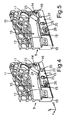
- Fig. 12 is shown in a perspective view of another embodiment.
- two slide elements 21 a and 21 b, each with a coupling wedge 22a and 22b are formed as actuators.
- the slide elements 21a and 21b, in particular the coupling wedges 22a and 22b, are coupled to one another in such a way that a second coupling wedge is in a first horizontal direction (x direction) perpendicular to the height direction (y direction) during a movement of the first coupling wedge 22a 22b in the height direction (y-direction) is adjustable and thereby also the altitude of the lower boundary wall 12 and in particular of the section 15 is adjustable.
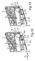
- Fig. 12 Here again the undisguised basic position is shown, in Fig.
- the maximum height adjustment of section 15 is shown. It is also the maximum upward position of the second slider element 21 b shown. This is achieved by starting from the representation in Fig. 12 the adjusting element 31 is rotated, thereby the first slider element 21a is displaced in the x direction and thereby the second slider element 21 b is lifted upwards.
- a further embodiment is shown in a perspective view, in which a trained as a slide member 21 actuator is movable in the height direction and to an inclined contact surface 21 c on a bottom 21d has.
- This inclined contact surface 21c is coupled to a contact surface 34 of the guide device 9, wherein the slider element 21 is moved in this first horizontal direction by an adjusting element 31, in particular an adjusting screw, adjustable in a first horizontal direction (x direction) and by the coupled contact surfaces 21 c and 34 is simultaneously adjustable in height direction.
- the section 15 is automatically adjusted in the vertical direction and thus changed the altitude.
- the underside 21d faces away from the section 15.
- Fig. 15 in turn, the state is shown in which the section 15 is lifted up to the maximum and also the slider element 21 has reached the maximum height position.
- Fig. 16 is shown a further embodiment in which no explicit own slide element is present. Rather, there is provided in the carrier 18, a trough or recess 35 in which an eccentric 25 is positioned and in the second horizontal direction (z-direction) can reciprocate.
- the eccentric 25 is located on the underside 20 of the section 15 also in Fig. 16 shown basic state, in which the section 15 is not yet raised to. If the eccentric 25 is then adjusted, it presses as shown in Fig. 17 go to section 15 above. In Fig. 17 is again shown the maximum raised state.
- the guide device 9 is generally formed in all versions for at least on one side of the door 3 feasible Höhnlagenver ein and thus configured for adjusting the door 3 to a side of the door 3 on the housing 4 arranged front panel 5 and / or 6. It can thus be a straight-line position of the door 3 in the direction of the height, if on both sides on the guide device 9 is carried out in each case an analogous lifting. If the door is to be tilted to some extent in the xy plane, such an altitude adjustment can only be done on one of the two sides. This is the preferred application in order to adjust the gap dimensions d1 and d2.
Abstract
Description
Die Erfindung betrifft ein Gargerät mit einem Gehäuse und einem Garraum, der durch eine Tür verschließbar ist. Das Gargerät umfasst eine Führungsvorrichtung, welche zumindest eine Führungskulisse aufweist, mit welcher die Tür gekoppelt ist und mit welcher die Tür beim Bewegen in den geöffneten Zustand in einen Aufnahmeraum in das Gehäuse versenkbar ist.The invention relates to a cooking appliance with a housing and a cooking chamber which can be closed by a door. The cooking device comprises a guide device, which has at least one guide slot, with which the door is coupled and with which the door is retractable when moving in the open state into a receiving space in the housing.
Aus dem Stand der Technik sind Gargeräte, wie beispielsweise ein Backofen oder ein Mikrowellengargerät oder ein Dampfgargerät bekannt, die Garräume aufweisen, in denen Lebensmittel zum Zubereiten eingebracht werden können. Ein derartiger Garraum ist üblicherweise frontseitig durch eine Tür verschließbar. Es sind hier Ausführungen bekannt, bei denen eine derartige Tür an einem Gehäuse angeordnet ist und lediglich um eine horizontale oder eine vertikale Achse verschwenkbar ist, um die Tür zu öffnen oder zu schließen.Cooking appliances, such as an oven or a microwave cooking appliance or a steam cooker, for example, are known from the prior art and have cooking chambers in which foodstuffs can be introduced for preparation. Such a cooking chamber is usually closed at the front by a door. Embodiments are known in which such a door is arranged on a housing and can only be pivoted about a horizontal or a vertical axis in order to open or close the door.
Darüber hinaus sind jedoch auch Ausführungen bekannt, bei denen eine derartige Tür beim Überführen von dem geschlossenen in den offenen Zustand in einen Schacht bzw. einen Aufnahmeraum unter dem Garraum in das Gehäuse versenkbar ist. Derartige Haushaltsgeräte sind beispielsweise aus der
Es ist auch bekannt, dass Gargeräte beispielsweise seitlich zu einer derartigen Tür am Gehäuse angeordnete frontseitige vertikale Blenden aufweisen, die beispielsweise als Designapplikationen positioniert sind. Die vertikalen Randseiten dieser Tür weisen üblicherweise ein gewisses Spaltmaß zu diesen Frontblenden auf. Aufgrund von Bauteiltoleranzen ist dieses Spaltmaß nicht an allen Stellen und über die gesamte Erstreckung gleich. Es kann dabei vorgesehen sein, dass diese Frontblenden in ihrer Position geringfügig verschoben werden können, um dann die entsprechende Spaltmaßeinstellung zur Tür durchführen zu können. Dies ist jedoch im Hinblick auf die Befestigung dieser Frontblenden schwierig, andererseits die Spaltmaßeinstellung begrenzt.It is also known that cooking appliances have, for example, front vertical shutters arranged laterally to such a door on the housing, which are positioned, for example, as design applications. The vertical edge sides of this door usually have a certain gap to these front panels. Due to component tolerances, this gap is not the same at all points and over the entire extension. It may be provided that these front panels can be moved slightly in their position in order to then perform the appropriate gap dimension adjustment to the door. However, this is with regard to Attachment of these front panels difficult, on the other hand limits the gap setting.
Es ist Aufgabe der vorliegenden Erfindung, ein Gargerät zu schaffen, bei welchem die Positionierung einer Tür, die in einen Aufnahmeraum des Gargeräts versenkbar ist, insbesondere im geschlossenen Zustand verbessert ist.It is an object of the present invention to provide a cooking appliance in which the positioning of a door, which is retractable into a receiving space of the cooking appliance, in particular in the closed state is improved.
Diese Aufgabe wird durch ein Gargerät, welche die Merkmale nach Anspruch 1 aufweist, gelöst.This object is achieved by a cooking appliance having the features of
Ein erfindungsgemäßes Gargerät umfasst ein Gehäuse und einen Garraum, der durch eine Tür verschließbar ist. Das Gargerät weist darüber hinaus eine Führungsvorrichtung auf, welche zumindest eine Führungskulisse umfasst, mit welcher die Tür gekoppelt ist und mit welcher die Tür bei Bewegen in den geöffneten Zustand in einen Aufnahmeraum in das Gehäuse versenkbar ist. Ein wesentlicher Gedanke der Erfindung besteht darin, dass die Führungsvorrichtung zur Höhenlagenverstellung und somit zur Justange der Höhenlage der Tür relativ zum Gehäuse ausgebildet ist. Es ist somit bei einem Gargerät mit einer versenkbaren Tür nunmehr auch die Möglichkeit geschaffen, eine Lageeinstellung der Tür durchzuführen. Dazu ist die Führungsvorrichtung multifunktionell ausgestaltet, da sie einerseits zur Führung der Tür beim Versenken und Herausfahren gestaltet ist, andererseits auch zugleich diese Positionsveränderung und insbesondere die Höhenlagenverstellung der Tür im geschlossenen Zustand ermöglicht. Dadurch lässt sich insbesondere im geschlossenen Zustand der Tür deren Position zumindest an einer Randseite in der vertikalen Richtung und somit in der Höhenlage verändern, so dass unterschiedliche Relativpositionen der Tür im geschlossenen Zustand zum Gehäuse und insbesondere auch zu benachbarten Frontblenden am Gehäuse einstellbar sind. Besonders bevorzugt ist es daher, dass durch diese Ausgestaltung auch Spaltenmaße zu benachbarten Frontblenden einfach und zuverlässig sowie dauerhaft beständig genau einstellbar sind.An inventive cooking appliance comprises a housing and a cooking chamber which can be closed by a door. The cooking appliance furthermore has a guide device, which comprises at least one guide slot with which the door is coupled and with which the door can be retracted into a housing in the housing when moved to the open state. An essential idea of the invention is that the guide device is designed for height adjustment and thus to Justange the altitude of the door relative to the housing. It is thus created in a cooking appliance with a retractable door now also the opportunity to perform a position adjustment of the door. For this purpose, the guide device is designed multifunctional, since it is designed on the one hand to guide the door when sinking and retracting, on the other hand also this position change and in particular allows the height adjustment of the door in the closed state. This makes it possible, in particular in the closed state of the door whose position change at least on one edge side in the vertical direction and thus in the altitude, so that different relative positions of the door in the closed state to the housing and in particular to adjacent front panels on the housing are adjustable. It is therefore particularly preferred that, by virtue of this embodiment, even gap dimensions to adjacent front panels can be precisely and simply and reliably permanently and permanently set.
Vorzugsweise ist vorgesehen, dass die Führungskulisse als Höhenverstelleinrichtung für die Tür zumindest in deren geschlossenen Zustand ausgebildet ist. Da sich gerade in diesem Positionszustand der Tür frontseitig die Spaltmaße zu benachbarten Frontblenden darstellen, ist es hier von besonderer Wesentlichkeit, diese Spaltmaße genau einzustellen und beibehalten zu können.It is preferably provided that the guide slot is designed as a height adjustment device for the door at least in its closed state. Since just in this position state of the door front side, the gap dimensions to adjacent front panels represent, it is of particular importance to be able to adjust these gaps exactly and maintain.
Vorzugsweise ist vorgesehen, dass eine untere Begrenzungswand der Führungskulisse zumindest abschnittweise in der Höhe zur Höhenlagenverstellung der Tür verstellbar ist. Die Führungskulisse ist somit in vertikaler Richtung betrachtet zumindest nach unten hin durch eine Begrenzungswand begrenzt, auf der dann gegebenenfalls auch ein Bewegungsmittel, wie eine Rolle oder ein Kugellager oder dergleichen sich auflegen und entlang gleiten kann, wenn die Tür relativ zum Gehäuse bewegt wird. Gerade diese Begrenzungswand ist somit wesentlicher und sehr direkter Einflussfaktor auf die jeweilige Lage der Tür. Es ist daher von besonderer Vorteilhaftigkeit, wenn gerade dieses Bauteil nicht starr am Gehäuse sitzt, sondern zumindest bereichsweise relativ dazu bewegbar ist, so dass in mechanischer Wechselwirkung mit der Tür eine unmittelbare Höhenlagenveränderung eintritt. Darüber hinaus ist diese Begrenzungswand als solche auch mechanisch stabil, so dass sie auch diese Bewegbarkeit und Höhenverstellung zuverlässig und dauerhaft verschleißarm gewährleisten kann.It is preferably provided that a lower boundary wall of the guide slot is at least partially adjustable in height for height adjustment of the door. The guide slot is thus viewed in the vertical direction at least downwardly bounded by a boundary wall on which then optionally also a moving means, such as a roller or a ball bearing or the like can hang up and slide along when the door is moved relative to the housing. Just this boundary wall is thus essential and very direct influencing factor on the respective position of the door. It is therefore of particular advantage if just this component is not rigidly seated on the housing, but at least partially movable relative thereto, so that in mechanical interaction with the door an immediate change in altitude occurs. In addition, this boundary wall as such is also mechanically stable, so that it can ensure wear and height adjustment reliably and permanently wear.
Vorzugsweise ist vorgesehen, dass die Begrenzungswand am vorderen Ende in der Höhenlage verstellbar ist. Diese Ausgestaltung ist dahingehend besonders hervorzuheben, da gerade im geschlossenen Zustand der Tür dieses Bewegungsmittel der Tür an dem vorderen Ende der Begrenzungswand sitzt bzw. auf diesem aufsitzt und somit gerade dann an dieser Stelle durch die Bewegbarkeit und Höhenveränderung eine sehr direkte und genaue Positionsveränderung erreichbar ist. Darüber hinaus ist es gerade bei dieser Ausgestaltung dann auch nicht mehr erforderlich, dass mittlere oder hintere Abschnitte der Begrenzungswand bewegbar sein müssen, so dass diese starr gestaltet werden können. Zum einen ist dadurch auch dann die mechanische Stabilität der gesamten Begrenzungswand verbessert und die positionsgenaue Anbindung an Gehäuseteile erreicht.It is preferably provided that the boundary wall at the front end in the altitude is adjustable. This embodiment is to be particularly emphasized, since just sitting in the closed state of the door of this movement means the door at the front end of the boundary wall or seated on this and thus just then at this point by the mobility and height change a very direct and accurate position change can be achieved , Moreover, in this embodiment, it is no longer necessary for the middle or rear sections of the boundary wall to be movable, so that they can be made rigid. On the one hand, this also improves the mechanical stability of the entire boundary wall and achieves the positionally accurate connection to housing parts.
Vorzugsweise ist vorgesehen, dass die Begrenzungswand im vorderen Bereich durch einen in der Höhe bewegbaren Einleger gebildet ist. Dadurch lassen sich die oben genannten Vorteile nochmals begünstigen und auch individuell auf die jeweiligen Anforderungen optimieren. Denn unterschiedliche Gargeräte können im Hinblick auf Ausgestaltung betreffend die Größe und das Gewicht sowie der Komponentenbestückung variabel gestaltet sein, so dass hier auch unterschiedliche Gewichte auf eine derartige Begrenzungswand und insbesondere den bewegbaren Teil einwirken können. Durch einen derartigen separaten Einleger, der somit einen Teilabschnitt der unteren Begrenzungswand bildet, kann darauf individuell reagiert werden, so dass auch hier höchsten mechanischen Beanspruchungen und präzisen Höhenverstellungen Rechnung getragen werden kann.It is preferably provided that the boundary wall is formed in the front region by a vertically movable insert. As a result, the advantages mentioned above can once again be favored and also optimized individually to the respective requirements. Because different cooking appliances can with regard to design regarding the size and weight and the component assembly be designed variable, so that here also different weights can act on such a boundary wall and in particular the movable part. By such a separate insert, which thus forms a portion of the lower boundary wall, it can be responded to individually, so that even here highest mechanical stresses and precise height adjustments can be accommodated.
Vorzugsweise ist vorgesehen, dass der Einleger als Streifen und insbesondere aus Stahl, beispielsweise Federstahl, ausgebildet ist. Diese Spezifikation ist bezüglich der oben genannten Vorteile bevorzugt.It is preferably provided that the insert is designed as a strip and in particular made of steel, for example spring steel. This specification is preferred in terms of the above advantages.
Vorzugsweise ist vorgesehen, dass eine Betätigungsvorrichtung für die Begrenzungswand ausgebildet ist, welche mit zumindest einem Betätigungselement relativ zur Begrenzungswand bewegbar und mit dieser zur Höhenlagenverstellung koppelbar ist. Es wird somit insbesondere eine mechanische Ausgestaltung vorgesehen, die als separate Komponente auf die Begrenzungswand in ihrem bewegbaren Abschnitt einwirkt, um deren Höhenverstellung zu bewirken. Dadurch wird eine sehr robuste Ausgestaltung erreicht, die in Bezug auf mechanische Belastbarkeit und auch thermische Einflüsse, wie sie in einem Gargerät vorliegen können, unempfindlich sind. Insbesondere ist vorgesehen, dass das Betätigungselement unter der Begrenzungswand angeordnet ist. Durch diese Ausgestaltung wird ohnehin vorhandener Bauraum sinnvoll genutzt und andererseits die Führungskulisse nicht unnötig begrenzt und ihr Bauraum nicht eingeschränkt. Darüber hinaus lässt sich durch diese Ausgestaltung auch aufgrund der Gewichtskraft eine Situation schaffen, bei der das angehobene und in der Höhenlage verstellbare Teil der Begrenzungswand auch von unten abgestützt wird und somit auf dem Betätigungselement quasi aufliegt. Eine präzise eingestellte Höhenlage bleibt daher auch dauerhaft genau erhalten.It is preferably provided that an actuating device for the boundary wall is formed, which is movable with at least one actuating element relative to the boundary wall and can be coupled with this for height adjustment. Thus, in particular, a mechanical design is provided which acts as a separate component on the boundary wall in its movable section in order to effect its height adjustment. As a result, a very robust embodiment is achieved, which are insensitive in terms of mechanical strength and thermal influences, such as may be present in a cooking appliance. In particular, it is provided that the actuating element is arranged below the boundary wall. By this configuration already existing space is used meaningful and on the other hand, the guide slot is not unnecessarily limited and their space is not limited. In addition, this situation can also create a situation due to the weight, in which the raised and adjustable in height portion of the boundary wall is also supported from below and thus rests on the actuator quasi. A precisely set altitude therefore remains permanently well preserved.
Vorzugsweise ist vorgesehen, dass die Betätigungsvorrichtung ein Schieberelement aufweist, welches einen Koppelkeil als Betätigungselement aufweist. Der Koppelkeil umfasst eine schräge Anlagefläche, die mit einer Anlagefläche an einer Unterseite der unteren Begrenzungswand kontaktiert ist. Insbesondere ist auch diese Anlagefläche an der Unterseite der unteren Begrenzungswand geschrägt, so dass beim Einwirken des Betätigungselements auf diesen bewegbaren Teil der Begrenzungswand ein ruckfreies Entlanggleiten der Anlageflächen aneinander erreicht ist.It is preferably provided that the actuating device has a slide element which has a coupling wedge as the actuating element. The coupling wedge comprises an inclined contact surface, which is contacted with a contact surface on an underside of the lower boundary wall. In particular, this contact surface is bevelled on the underside of the lower boundary wall, so that when exposed to the Actuating element on these movable part of the boundary wall a jerk-free sliding along the contact surfaces is achieved together.
Insbesondere ist der Koppelkeil an seinem vorderen Ende verjüngt ausgebildet und somit an dem dem vorderen Ende der Begrenzungswand zugewandten Ende sich verjüngend gestaltet.In particular, the coupling wedge is tapered at its front end and thus designed to taper at the end facing the front end of the boundary wall.
Vorzugsweise ist vorgesehen, dass zur Höhenlagenverstellung der Begrenzungswand das Schieberelement horizontal verschiebbar ist und durch das Entlanggleiten der Anlagefläche des Schieberelements an der Anlagefläche der Begrenzungswand diese Begrenzungswand in der Höhenlage veränderbar ist. Die Höhenlagenveränderung erfolgt dabei somit senkrecht zu dieser horizontalen Bewegung, so dass die diesbezüglichen Bewegungsrichtungen senkrecht aufeinander stehen. Durch diese Ausgestaltung lässt sich ein sehr einfaches Wirkprinzip realisieren, welches im Platzbedarf minimiert ist und dennoch die Höhenlage sehr direkt und ohne eine Vielzahl von zusätzlichen Übertragerelementen ermöglicht.Preferably, it is provided that for height adjustment of the boundary wall, the slider element is horizontally displaceable and by sliding along the contact surface of the slider element on the contact surface of the boundary wall, this boundary wall is changeable in the altitude. The change in altitude is thus perpendicular to this horizontal movement, so that the relevant directions of movement are perpendicular to each other. By this configuration, a very simple operating principle can be realized, which is minimized in space requirements and still allows the altitude very directly and without a variety of additional transformer elements.
Vorzugsweise ist vorgesehen, dass das Schieberelement an seiner der Begrenzungswand abgewandten Unterseite eine Rasteinrichtung aufweist, die zur Positionssicherung des Schieberlements zur Verrastung mit einer Gegenrastung ausgebildet ist. Diese Ausgestaltung ist dahingehend vorteilhaft, dass eine eingestellte Position der Begrenzungswand dauerhaft beibehalten werden kann, da sich durch die Verrastung des Schieberelements auch dieses an einem Gehäusebauteil arretiert und somit nicht mehr unerwünscht verschoben werden kann. Gerade dann, wenn das Schieberelement unter den bewegbaren Teil der Begrenzungswand angeordnet ist, ergibt sich dann ein sehr funktionelles zusammenspielendes Wirkprinzip der Bauteile.Preferably, it is provided that the slide element on its side facing away from the boundary wall bottom has a latching device which is designed to lock the position of the Schieberlements for latching with a counter-latching. This embodiment is advantageous in that a set position of the boundary wall can be permanently maintained because locked by the locking of the slider element and this on a housing component and thus can not be moved undesirable. Just when the slide element is arranged under the movable part of the boundary wall, then results in a very functional interacting action principle of the components.
Insbesondere ist in dem Zusammenhang vorgesehen, dass durch die auf das Schieberelement von oben drückende Begrenzungswand das Schieberelement in die Gegenrastung gedrückt ist. Die Positionsarretierung des Schieberelements ist dadurch begünstigt.In particular, it is provided in the context that the slider element is pressed into the counter-locking by the pushing on the slider element from above boundary wall. The position locking of the slider element is favored.
Vorzugsweise ist vorgesehen, dass der höhenverstellbare Teil der unteren Begrenzungswand in seiner Grundstellung und somit in einer nicht nach oben angehobenen Verstellposition vorzugsweise bereits mit dem Betätigungselement mechanisch kontaktiert ist, so dass kein unerwünschtes nach unten Drücken der Begrenzungswand erfolgen kann. Ausgehend von dieser Grundstellung und der Bewegung des Betätigungselements wird dann nur immer eine Situation erreicht, bei der dieser bewegbare Teil der Begrenzungswand in der Höhe verstellt und nach oben gedrückt wird, so dass gerade diese dann von diesem bewegbaren Teil der Begrenzungswand nach unten wirkende und auf das Schieberelement drückende Kraft größer wird, so dass dieser Andrückmechanismus von dem bewegbaren Teil auf das Schieberelement vergrößert ist.It is preferably provided that the height-adjustable part of the lower boundary wall in its normal position and thus in a non-upward raised adjustment position is preferably already mechanically contacted with the actuating element, so that no undesirable down pressing the boundary wall can be done. Starting from this basic position and the movement of the actuating element then only a situation is reached in which this movable part of the boundary wall is adjusted in height and pushed upwards, so that just then then from this movable part of the boundary wall acting down and on the slider element pressing force is larger, so that this pressing mechanism is increased from the movable part to the slider element.
Vorzugsweise ist vorgesehen, dass das Schieberelement mit einem Exzenter gekoppelt ist, und durch Betätigen des Exzenters das Schieberelement horizontal verschiebbar ist. Dadurch lässt sich eine sehr gleichmäßige und auch in sehr kleinen Wegabschnitten und somit in Nuancen durchführbare horizontale Verschiebung ermöglichen, so dass dadurch auch entsprechend kleine Veränderungen in der Höhenlage des bewegbaren Teils der Begrenzungswand einstellbar sind.It is preferably provided that the slider element is coupled to an eccentric, and by pressing the eccentric, the slider element is horizontally displaceable. As a result, a very uniform and even in very small sections and thus feasible in nuances horizontal displacement allow, so that also correspondingly small changes in the altitude of the movable part of the boundary wall can be adjusted.
Vorzugsweise ist vorgesehen, dass das Schieberelement mit einem Sicherungselement, insbesondere einer Sicherungsschraube, in seiner Verschiebeposition arretierbar ist. Diese Ausgestaltung kann zusätzlich zu der oben bereits genannten Rasteinrichtung mit der Gegenrastung vorgesehen sein oder aber auch ohne diese zusätzliche Rastmechanik ausgebildet sein.It is preferably provided that the slide element can be locked in its displaced position with a securing element, in particular a securing screw. This configuration may be provided in addition to the above-mentioned locking device with the counter-locking or be formed without this additional locking mechanism.
Vorzugsweise ist bei einer weiteren Ausführung vorgesehen, dass zwei Schieberelemente mit jeweils zumindest einem Koppelkeil als Betätigungselemente ausgebildet sind, welche derart miteinander gekoppelt sind, dass ein bei einer Bewegung des ersten Koppelkeils in eine senkrecht zur Höhenrichtung stehende erste horizontale Richtung zweiter Koppelkeil in eine weitere, senkrecht zur Höhenrichtung und zur ersten Horizontalrichtung stehende zweite horizontale Richtung bewegbar ist und dadurch die Höhenlage der Begrenzungswand verstellbar ist. Es wird somit ein mechanisches Zusammenwirken zweier Schieberelemente geschaffen, die sich in unterschiedliche, relativ zueinander senkrecht stehende Richtungen bewegen können, wenn sie aufeinander einwirken und dieser Bewegungsablauf dann derart auf die Begrenzungswand übertragen wird, dass diese dann in die dritte Raumrichtung bewegbar und anhebbar ist.Preferably, in a further embodiment, it is provided that two slide elements are each formed with at least one coupling wedge as actuating elements, which are coupled to each other in such a way that a second horizontal wedge in a second horizontal wedge direction perpendicular to the height direction moves into a further, perpendicular to the height direction and the first horizontal direction stationary second horizontal direction is movable and thereby the altitude of the boundary wall is adjustable. Thus, a mechanical interaction of two slide elements is created, which can move in different, relatively perpendicular directions when they act on each other and this movement is then transferred to the boundary wall so that it is then movable and raised in the third spatial direction.
Vorzugsweise ist vorgesehen, dass der zweite Koppelkeil durch ein Führungselement in der zweiten horizontalen Richtung geführt ist. Beispielsweise kann hier eine entsprechende Bohrung als Führungselement vorgesehen sein.It is preferably provided that the second coupling wedge is guided by a guide element in the second horizontal direction. For example, a corresponding bore can be provided here as a guide element.
Bei einer weiteren Ausführung ist vorzugsweise vorgesehen, dass zwei Schieberelemente mit jeweils zumindest einem Koppelkeil als Betätigungselemente ausgebildet sind, welche derart miteinander gekoppelt sind, dass ein bei einer Bewegung des ersten Koppelkeils in eine senkrecht zur Höhenrichtung stehende erste horizontale Richtung zweiter Koppelkeil in Höhenrichtung verstellbar ist und dadurch die Höhenlage der Begrenzungswand verstellbar ist.In a further embodiment, it is preferably provided that two slide elements are each formed with at least one coupling wedge as actuating elements which are coupled to one another so that a first horizontal direction of the second coupling wedge perpendicular to the height direction can be adjusted in the height direction during a movement of the first coupling wedge and thereby the altitude of the boundary wall is adjustable.
In vorteilhafter Ausführung ist vorgesehen, dass verjüngte Teilbereiche der Koppelkeile der zumindest zwei Schieberelemente aneinander anliegen und relativ zueinander bewegbar sind. Auch dadurch ist die sehr kontinuierliche und gleichmäßige Bewegung erreicht, so dass auch die Höhenlageeinstellung sehr präzise ermöglicht ist.In an advantageous embodiment, it is provided that tapered portions of the coupling wedges of the at least two slide elements abut each other and are movable relative to each other. This is also the very continuous and smooth movement is achieved, so that the altitude adjustment is very precise.
Vorzugsweise ist vorgesehen, dass das erste Schieberelement in Richtung der ersten horizontalen Richtung durch eine Feder vorgespannt ist. Dadurch lässt sich bei der Rückführung in den Ausgangszustand ein Automatismus erreichen.It is preferably provided that the first slider element is biased in the direction of the first horizontal direction by a spring. This can be achieved in the return to the initial state of an automatism.
Vorzugsweise ist vorgesehen, dass in Verlängerung der horizontalen Verschieberichtung des Schieberelements das Schieberelement mit einem Verstellelement, insbesondere einer Verstellschraube, gekoppelt ist, wobei das Verstellelement in einem vorderen Ende des Schieberelements mit diesem gekoppelt ist. Auch hier kann vorzugsweise eine Rückstellung durch eine Feder oder einen Einleger vorgesehen sein.It is preferably provided that in extension of the horizontal displacement direction of the slide element, the slide element is coupled to an adjusting element, in particular an adjusting screw, wherein the adjusting element is coupled in a front end of the slide element with this. Again, preferably a provision may be provided by a spring or an insert.
Vorzugsweise ist bei einer weiteren Ausführung vorgesehen, dass ein als Schieberelement ausgebildetes Betätigungselement der Betätigungsvorrichtung ausschließlich in Höhenrichtung bewegbar ist und dazu eine schräge Anlagefläche an einer Unterseite des Schieberelements mit einer Anlagefläche der Führungsvorrichtung gekoppelt ist. Es ist vorgesehen, dass ein in eine erste horizontale Richtung verstellbares Verstellelement das Schieberelement in diese erste horizontale Richtung bewegt und durch die gekoppelten Anlageflächen gleichzeitig eine Verstellung in Höhenrichtung möglich ist.In a further embodiment, it is preferably provided that an actuating element of the actuating device designed as a slide element can be moved exclusively in the vertical direction and, for this purpose, an inclined contact surface on an underside of the slide element is coupled to a contact surface of the guide device. It is provided that an adjustable in a first horizontal direction adjustment moves the slider element in this first horizontal direction and By the coupled contact surfaces at the same time an adjustment in the height direction is possible.
Bei einer weiteren Ausführung ist vorgesehen, dass das Betätigungselement ein Exzenter ist, der direkt an einer Unterseite der Begrenzungswand anliegt und durch eine Bewegung des Exzenters in eine horizontale Richtung eine Höhenverstellung der Begrenzungswand einstellbar ist.In a further embodiment it is provided that the actuating element is an eccentric, which rests directly on an underside of the boundary wall and a height adjustment of the boundary wall is adjustable by a movement of the eccentric in a horizontal direction.
Vorzugsweise ist vorgesehen, dass die Führungsvorrichtung zur zumindest an einer Seite der Tür durchführbaren Höhenlagenverstellung ausgebildet ist und zur Justage der Tür zu einer seitlich zur Tür an dem Gehäuse angeordneten Frontblende ausgebildet ist.It is preferably provided that the guide device is designed for at least on one side of the door feasible altitude adjustment and is designed for adjusting the door to a side of the door to the housing arranged front panel.
Vorzugsweise ist vorgesehen, dass die Führungsvorrichtung an zwei gegenüberliegenden Seiten in unteren Eckbereichen der Tür mit der Tür gekoppelt ist , insbesondere über zwei separate Führungskulissen, und zu dessen Justage der Höhenlage ausgebildet ist, wobei die Justage der Höhenlage auf einer Seite unabhängig von der Justage auf der anderen Seite durchführbar ist. Dadurch können auch Verkippungen der Tür erfolgen, so dass Spaltmaße zu benachbarten vertikalen Blenden eingestellt werden können.Preferably, it is provided that the guide device is coupled to the door on two opposite sides in lower corner regions of the door, in particular via two separate guide slots, and is adapted to its adjustment of the altitude, the adjustment of the altitude on one side regardless of the adjustment the other side is feasible. As a result, tilting of the door can also take place, so that gap dimensions can be set to adjacent vertical diaphragms.
Weitere Merkmale der Erfindung ergeben sich aus den Ansprüchen, den Figuren und der Figurenbeschreibung. Die vorstehend in der Beschreibung genannten Merkmale und Merkmalskombinationen sowie die nachfolgend in der Figurenbeschreibung genannten und/oder in den Figuren alleine gezeigten Merkmale und Merkmalskombinationen sind nicht nur in der jeweils angegebenen Kombination, sondern auch in anderen Kombinationen oder in Alleinstellung verwendbar, ohne den Rahmen der Erfindung zu verlassen. Es sind somit auch Ausführungen von der Erfindung als umfasst und offenbart anzusehen, die in den Figuren nicht explizit gezeigt und erläutert sind, jedoch durch separierte Merkmalskombinationen aus den erläuterten Ausführungen hervorgehen und erzeugbar sind.Further features of the invention will become apparent from the claims, the figures and the description of the figures. The features and feature combinations mentioned above in the description as well as the features and feature combinations mentioned below in the description of the figures and / or shown alone in the figures can be used not only in the respectively specified combination but also in other combinations or in isolation, without the scope of To leave invention. Thus, embodiments of the invention are to be regarded as encompassed and disclosed, which are not explicitly shown and explained in the figures, however, emerge and can be produced by separated combinations of features from the embodiments explained.
Ausführungsbeispiele der Erfindung werden nachfolgend anhand schematischer Zeichnungen näher erläutert. Es zeigen:
- Fig. 1
- eine Frontansicht auf ein Ausführungsbeispiel eines erfindungsgemäßen Gargeräts;
- Fig. 2
- eine perspektivische Darstellung eines Gehäuses des Gargeräts gemäß
Fig. 1 ; - Fig. 3
- eine vergrößerte Darstellung eines Teilausschnitts der Darstellung in
Fig. 2 ; - Fig. 4
- eine perspektivische Darstellung eines ersten Ausführungsbeispiels des Gargeräts im Bereich der Führungsvorrichtung in einem ersten Zustand;
- Fig. 5
- eine perspektivische Darstellung gemäß
Fig. 4 in einem zweiten Zustand; - Fig. 6
- eine perspektivische Darstellung eines weiteren Ausführungsbeispiels eines Gargeräts im Bereich der Führungsvorrichtung in einem ersten Zustand;
- Fig. 7
- die Darstellung gemäß
Fig. 6 in einem zweiten Zustand; - Fig. 8
- eine perspektivische Darstellung eines dritten Ausführungsbeispiels des Gargeräts im Bereich der Führungsvorrichtung in einem ersten Zustand;
- Fig. 9
- die Darstellung gemäß
Fig. 8 in einem zweiten Zustand; - Fig. 10
- eine perspektivische Darstellung eines vierten Ausführungsbeispiels des Gargeräts im Bereich der Führungsvorrichtung in einem ersten Zustand;
- Fig. 11
- eine Darstellung der Ausführung in
Fig. 10 in einem zweiten Zustand; - Fig. 12
- eine perspektivische Darstellung eines fünften Ausführungsbeispiels des Gargeräts im Bereich der Führungsvorrichtung in einem ersten Zustand;
- Fig. 13
- eine perspektivische Darstellung der Ausführung in
Fig. 12 in einem zweiten Zustand; - Fig. 14
- ein sechstes Ausführungsbeispiel des Gargeräts im Bereich der Führungsvorrichtung in einem ersten Zustand;
- Fig. 15
- eine perspektivische Darstellung der Ausführung in
Fig. 14 in einem zweiten Zustand; - Fig. 16
- eine perspektivische Darstellung eines siebten Ausführungsbeispiels des Gargeräts im Bereich der Führungsvorrichtung in einem ersten Zustand; und
- Fig. 17
- eine perspektivische Darstellung der Ausführung in
Fig. 16 in einem zweiten Zustand.
- Fig. 1
- a front view of an embodiment of a cooking appliance according to the invention;
- Fig. 2
- a perspective view of a housing of the cooking appliance according to
Fig. 1 ; - Fig. 3
- an enlarged view of a partial section of the illustration in
Fig. 2 ; - Fig. 4
- a perspective view of a first embodiment of the cooking appliance in the region of the guide device in a first state;
- Fig. 5
- a perspective view according to
Fig. 4 in a second state; - Fig. 6
- a perspective view of another embodiment of a cooking appliance in the region of the guide device in a first state;
- Fig. 7
- the representation according to
Fig. 6 in a second state; - Fig. 8
- a perspective view of a third embodiment of the cooking appliance in the region of the guide device in a first state;
- Fig. 9
- the representation according to
Fig. 8 in a second state; - Fig. 10
- a perspective view of a fourth embodiment of the cooking appliance in the region of the guide device in a first state;
- Fig. 11
- a representation of the execution in
Fig. 10 in a second state; - Fig. 12
- a perspective view of a fifth embodiment of the cooking appliance in the region of the guide device in a first state;
- Fig. 13
- a perspective view of the embodiment in
Fig. 12 in a second state; - Fig. 14
- a sixth embodiment of the cooking appliance in the region of the guide device in a first state;
- Fig. 15
- a perspective view of the embodiment in
Fig. 14 in a second state; - Fig. 16
- a perspective view of a seventh embodiment of the cooking appliance in the region of the guide device in a first state; and
- Fig. 17
- a perspective view of the embodiment in
Fig. 16 in a second state.
In den Figuren werden gleiche oder funktionsgleiche Elemente mit den gleichen Bezugszeichen versehen.In the figures, identical or functionally identical elements are provided with the same reference numerals.
In
Das Gargerät 1 umfasst auch ein Gehäuse 4, in welchem die Muffel 7 mit dem Garraum 2 angeordnet ist. An dem Gehäuse 4 sind frontseitig und zur Seite hin Frontblenden 5 und 6 benachbart zur Tür 3 angeordnet. Die Frontblenden 5 und 6 sind streifenartige Elemente, die sich zumindest über die gesamte Höhe (Erstreckung in y-Richtung) und somit in vertikaler Richtung der Tür 3 erstrecken. Sie sind beispielsweise über Befestigungen, wie Kunststoffbauteile, am Gehäuse 4 befestigt. Die Position dieser Frontblenden 5 und 6 ist im Vergleich zur Position der Tür 3 immer relativ genau.The
Die Tür 3 ist keine Klapptür als solche, sondern in das Gehäuse 4 hinein versenkbar.The
In der Darstellung gemäß
Dazu umfasst das Gargerät 1 eine Führungsvorrichtung 9. Die Führungsvorrichtung 9 ist an den gegenüberliegenden vertikalen Wänden des Gehäuses 4 jeweils ausgebildet, so dass die Tür 3 an beiden gegenüberliegenden Seiten entsprechend bewegungsgeführt ist.For this purpose, the
In
Die Führungskulisse 10 umfasst eine obere Begrenzungswand 11 und eine untere Begrenzungswand 12. Darüber hinaus ist auch noch eine seitliche Begrenzungswand 13 vorgesehen.The
Das Kugellager der Tür 3 sitzt quasi auf der unteren Begrenzungswand 12 auf.The ball bearing of the
Im geschlossenen Zustand der Tür 3, wie in
In der gezeigten Ausführung ist vorgesehen, dass die Führungskulisse 10, insbesondere die untere Begrenzungswand 12, abschnittsweise bewegbar ist und somit in der Höhenlage (y-Richtung) veränderbar ist.In the embodiment shown it is provided that the
Dazu ist vorgesehen, dass somit die Führungsvorrichtung 9 zur Höhenlageverstellung der Tür 3 ausgebildet ist. Insbesondere im geschlossenen Zustand der Tür 3 ist die Führungskulisse 10 als Höhenverstelleinrichtung für die Tür 3 ausgebildet. Bevorzugt ist dazu die untere Begrenzungswand 12 zumindest abschnittsweise in der Höhe zur Höhenlagenstellung der Tür 3 verstellbar.For this purpose, it is provided that thus the
Dazu ist ein vorderer Abschnitt 15 der unteren Begrenzungswand 12 entsprechend relativ bewegbar angeordnet.For this purpose, a
Im Ausführungsbeispiel ist vorgesehen, dass dazu ein separates Bauteil in Form eines Einlegers, der insbesondere aus Federstahl ist, diesen Abschnitt 15 bildet. Der Einleger in Form des Abschnitts 15 bildet somit auch das vordere Ende der unteren Begrenzungswand 12, wobei der Abschnitt 15 dazu ein vorderes Ende 16 aufweist, welches dann auch das vordere Ende 14 der Führungskulisse 10 bildet.In the exemplary embodiment, it is provided that for this purpose a separate component in the form of an insert, which is in particular made of spring steel, forms this
Der Abschnitt 15 ist streifenartig ausgebildet und ist wiederum abschnittsweise zumindest nicht-geradlinig ausgestaltet und weist dazu einen nach unten gekrümmten Bereich 17 auf.The
In
Die Betätigungsvorrichtung 19 umfasst ein Schieberelement 21, welches an einem vorderen Ende, welches dem vorderen Ende 14 der Führungskulisse 10 und somit auch dem Ende 16 des Abschnitts 15 zugewandt ist, einen Koppelkeil 22 mit einer schrägen Anlagefläche 23 aufweist. Die schräge Anlagefläche 23 liegt vorzugsweise an einer Unterseite 24 des Abschnitts 15 an. Insbesondere erfolgt dies im Bereich des gekrümmten Bereichs 17 des Abschnitts 15.The
Das als Schieberelement 21 ausgebildete Betätigungselement ist im Ausführungsbeispiel nur in eine zweite horizontale Richtung, nämlich in z-Richtung und somit in Richtung der Erstreckung der Führungskulisse 10 relativ zum Abschnitt 15 der unteren Begrenzungswand 12 verschiebbar. Dazu ist ein Exzenter 25 vorgesehen. Wird der Exzenter 25 betätigt, so erfolgt eine Horizontalverschiebung des Schieberelements 21 in die genannte zweite horizontale Richtung (z-Richtung), wodurch gemäß der Darstellung in
Dadurch lässt sich ein in
Die Betätigungsvorrichtung 19 umfasst im Ausführungsbeispiel darüber hinaus auch noch ein Sicherungselement in Form einer Sicherungsschraube 26, mit der die gemäß der Darstellung in
In
Diese Rasteinrichtung 27 und die Gegenrastung 29 können auch bei den Ausführungen in
Durch die Rasteinrichtung 27 und die Gegenrastung 29 ist auch eine feine vertikale Verstellung des Einlegers in Form des Abschnitts 15 möglich.By the latching
Bei der Erfindung ist es somit nicht mehr erforderlich, kann jedoch auch noch vorgesehen sein, dass auch die Frontblenden 5 und/oder 6 relativ zur Tür 3 am Gehäuse 4 bewegbar angeordnet sind und somit verstellbar positioniert werden können.In the invention, it is thus no longer necessary, but may also be provided that the front panels 5 and / or 6 are arranged relative to the
Gerade bei Systemen, die jedoch beispielsweise zwei Gargeräte 1 in vertikaler Richtung betrachtet übereinander angeordnet aufweisen, und sich die Frontblenden 5 und 6 jeweils einstückig über die gesamte Höhe beider Gargeräte 1 erstrecken, ist eine derartige Positionsveränderung der Frontblenden 5 und 6 nicht mehr möglich. Gerade auch bei derartigen Systemen ist die vorgeschlagene Erfindung von wesentlichem Vorteil, da die jeweiligen einzelnen Geräte unabhängig voneinander dann individuell durch die positionelle Änderung der Türen die Spaltmaße d1 und d2 einstellen können.Especially in systems that, for example, two
In
In
In der Ausführung gemäß
Bei einer weiteren Ausführung gemäß der Darstellung in
Vorzugsweise ist vorgesehen, dass zusätzlich eine in
In
In
In
Dadurch wird automatisch auch der Abschnitt 15 in Höhenrichtung verstellt und somit die Höhenlage geändert. Die Unterseite 21d ist dem Abschnitt 15 abgewandt. In
Bei den bisher erläuterten Ausführungen können noch jeweils Rasteinrichtungen 27 und Gegenrastungen 29 vorgesehen sein. Darüber hinaus können auch jeweils einzelne Merkmale und Merkmalskombinationen der einzelnen Ausführungsbeispiele bei anderen Ausführungen vorgesehen sein oder darüber hinaus zu neuen, bisher nicht erläuterten Ausführungsbeispielen zusammengefasst werden.In the embodiments described so far still locking
In
Die Führungsvorrichtung 9 ist allgemein bei allen Ausführungen zur zumindest an einer Seite der Tür 3 durchführbaren Höhnlagenverstellung ausgebildet und somit zur Justage der Tür 3 zu einer seitlich zur Tür 3 an dem Gehäuse 4 angeordneten Frontblende 5 und/oder 6 ausgebildet. Es kann somit eine geradlinige Stellung der Tür 3 in Richtung der Höhe erfolgen, wenn beidseits über die Führungsvorrichtung 9 jeweils ein analoges Anheben erfolgt. Soll die Tür in gewissem Maße in der x-y-Ebene verkippt werden, so kann eine derartige Höhenlagenverstellung nur an einer der beiden Seiten erfolgen. Dies ist der bevorzugte Anwendungsfall, um die Spaltmaße d1 und d2 einstellen zu können.The
- 11
- GargerätCooking appliance
- 22
- Garraumoven
- 33
- Türdoor
- 44
- Gehäusecasing
- 55
- Frontblendefront panel
- 66
- Frontblendefront panel
- 77
- Muffelmuffle
- 88th
- Aufnahmeraumaccommodation space
- 99
- Führungsvorrichtungguiding device
- 1010
- Führungskulisseguide link
- 1111
- obere Begrenzungswandupper boundary wall
- 1212
- untere Begrenzungswandlower boundary wall
- 1313
- Begrenzungswandboundary wall
- 1414
- vorderes Endefront end
- 1515
- Abschnittsection
- 1616
- vorderes Endefront end
- 1717
- gekrümmter Bereichcurved area
- 1818
- Trägercarrier
- 1919
- Betätigungsvorrichtungactuator
- 2020
- Unterseitebottom
- 21, 21a, 21b21, 21a, 21b
- Schieberelementslide element
- 21c21c
- Anlageflächecontact surface
- 21d21d
- Unterseitebottom
- 22, 22a, 22b, 22c22, 22a, 22b, 22c
- Koppelkeilcoupling wedge
- 22d22d
- Anlageflächecontact surface
- 2323
- Anlageflächecontact surface
- 2424
- Unterseitebottom
- 2525
- Exzentereccentric
- 2626
- Sicherungsschraubelocking screw
- 2727
- Rasteinrichtunglocking device
- 2828
- Unterseitebottom
- 2929
- GegenrastungGegenrastung
- 3030
- Führungselementguide element
- 3131
- Verstellelementadjustment
- 3232
- Verstellelementadjustment
- 3333
- Bohrungdrilling
- 3434
- Anlageflächecontact surface
- 3535
- Vertiefungdeepening
- d1, d2d1, d2
- Spaltmaßeclearances
Claims (23)
Applications Claiming Priority (1)
| Application Number | Priority Date | Filing Date | Title |
|---|---|---|---|
| DE102012222161.1A DE102012222161A1 (en) | 2012-12-04 | 2012-12-04 | Cooking appliance with retractable door and height-adjustable guide slot |
Publications (3)
| Publication Number | Publication Date |
|---|---|
| EP2741014A2 true EP2741014A2 (en) | 2014-06-11 |
| EP2741014A3 EP2741014A3 (en) | 2015-05-06 |
| EP2741014B1 EP2741014B1 (en) | 2016-10-12 |
Family
ID=49641674
Family Applications (1)
| Application Number | Title | Priority Date | Filing Date |
|---|---|---|---|
| EP13194660.0A Active EP2741014B1 (en) | 2012-12-04 | 2013-11-27 | Cooking device with stowable door and height-adjustable guiding rail |
Country Status (4)
| Country | Link |
|---|---|
| EP (1) | EP2741014B1 (en) |
| DE (1) | DE102012222161A1 (en) |
| ES (1) | ES2603285T3 (en) |
| PL (1) | PL2741014T3 (en) |
Cited By (2)
| Publication number | Priority date | Publication date | Assignee | Title |
|---|---|---|---|---|
| US10168055B2 (en) * | 2014-08-19 | 2019-01-01 | BSH Hausgeräte GmbH | Household device having a door and electrical contacts in the region of a door guide |
| WO2020139219A1 (en) * | 2018-12-26 | 2020-07-02 | Arcelik Anonim Sirketi | An oven comprising a height-adjustable rail |
Families Citing this family (2)
| Publication number | Priority date | Publication date | Assignee | Title |
|---|---|---|---|---|
| DE102018211693A1 (en) * | 2018-07-13 | 2020-01-16 | BSH Hausgeräte GmbH | Cooking appliance with a specific design for the edge strips |
| DE102019213486A1 (en) * | 2019-09-05 | 2021-03-11 | BSH Hausgeräte GmbH | Cooking device with a specific door opening device for automatically pivoting a retractable door of the cooking device, as well as a method |
Citations (2)
| Publication number | Priority date | Publication date | Assignee | Title |
|---|---|---|---|---|
| WO2003073004A1 (en) | 2002-02-27 | 2003-09-04 | BSH Bosch und Siemens Hausgeräte GmbH | Household device |
| DE102008010502A1 (en) | 2008-02-22 | 2009-08-27 | BSH Bosch und Siemens Hausgeräte GmbH | House door guiding device |
Family Cites Families (7)
| Publication number | Priority date | Publication date | Assignee | Title |
|---|---|---|---|---|
| US2113544A (en) * | 1937-04-13 | 1938-04-05 | Welbilt Stove Company Inc | Broiler oven pull-out drawer |
| US2551843A (en) * | 1945-11-23 | 1951-05-08 | Lyon Metal Products Inc | Drawer aligning means for cabinets |
| JP4686034B2 (en) * | 2001-01-31 | 2011-05-18 | 家研販売株式会社 | Rail height adjustment unit |
| US6902244B1 (en) * | 2003-12-15 | 2005-06-07 | Protrend Co., Ltd. | Drawer rail structure allowing adjusting of vertical position of drawer front panel |
| DE102007058690A1 (en) * | 2007-12-06 | 2009-06-10 | BSH Bosch und Siemens Hausgeräte GmbH | Door adjustment device for household appliance i.e. baking-oven, has adjusting unit connected with hinge part of hinge device of door for vertical position adjustment of hinge part and supported in inner side of base of household appliance |
| DE202009004771U1 (en) * | 2009-04-30 | 2010-09-09 | Paul Hettich Gmbh & Co. Kg | Device for adjusting the height of a guided in a household appliance via at least one pullout guide tray |
| DE102011083512A1 (en) * | 2011-09-27 | 2013-03-28 | BSH Bosch und Siemens Hausgeräte GmbH | Domestic appliance with a receiving space and a door for closing the receiving space, and method for operating a door of a household appliance |
-
2012
- 2012-12-04 DE DE102012222161.1A patent/DE102012222161A1/en not_active Withdrawn
-
2013
- 2013-11-27 ES ES13194660.0T patent/ES2603285T3/en active Active
- 2013-11-27 PL PL13194660T patent/PL2741014T3/en unknown
- 2013-11-27 EP EP13194660.0A patent/EP2741014B1/en active Active
Patent Citations (2)
| Publication number | Priority date | Publication date | Assignee | Title |
|---|---|---|---|---|
| WO2003073004A1 (en) | 2002-02-27 | 2003-09-04 | BSH Bosch und Siemens Hausgeräte GmbH | Household device |
| DE102008010502A1 (en) | 2008-02-22 | 2009-08-27 | BSH Bosch und Siemens Hausgeräte GmbH | House door guiding device |
Cited By (2)
| Publication number | Priority date | Publication date | Assignee | Title |
|---|---|---|---|---|
| US10168055B2 (en) * | 2014-08-19 | 2019-01-01 | BSH Hausgeräte GmbH | Household device having a door and electrical contacts in the region of a door guide |
| WO2020139219A1 (en) * | 2018-12-26 | 2020-07-02 | Arcelik Anonim Sirketi | An oven comprising a height-adjustable rail |
Also Published As
| Publication number | Publication date |
|---|---|
| DE102012222161A1 (en) | 2014-06-05 |
| EP2741014B1 (en) | 2016-10-12 |
| ES2603285T3 (en) | 2017-02-24 |
| PL2741014T3 (en) | 2017-03-31 |
| EP2741014A3 (en) | 2015-05-06 |
Similar Documents
| Publication | Publication Date | Title |
|---|---|---|
| EP2704605B1 (en) | Drawer pull-out guide | |
| EP2661195B1 (en) | Lockable ejection device with overload mechanism | |
| EP2651263B1 (en) | Drawer pull-out guide | |
| EP1550385B1 (en) | Device for adjusting the height of a drawer | |
| AT507656B1 (en) | ARRANGEMENT FOR LOCKING AND EJECTING A FURNITURE PART | |
| EP2411611B1 (en) | Furniture hinge | |
| EP3707331B1 (en) | Side wall of a body of a piece of furniture with a wing fitting and piece of furniture comprising a side wall | |
| EP3839185A1 (en) | Guidance system for guiding a movable furniture part | |
| EP3452319B1 (en) | Arrangement with a cover for a vehicle roof, vehicle roof for a motor vehicle and method for moving a cover for a vehicle roof | |
| EP2741014B1 (en) | Cooking device with stowable door and height-adjustable guiding rail | |
| EP1421876B1 (en) | Front panel adjustment device for drawers | |
| EP3684223B1 (en) | Coupling device for drawer with subsequent latching | |
| EP2916686B1 (en) | Sliding-guide element and tabletop-fastening system for fastening a tabletop in a displaceable manner | |
| EP3067497A1 (en) | Fitting for sliding doors for an item of furniture | |
| EP2198746B1 (en) | Adjustment device for aligning a piece of furniture | |
| AT501777A2 (en) | DRAWER GUIDE | |
| EP0957714A1 (en) | Flush-mounted extraction guide for drawers etc. | |
| EP3201413B1 (en) | Fitting arrangement | |
| AT15365U1 (en) | glazing system | |
| EP3356629B1 (en) | Fitting for a sliding door and method for mounting a sliding door | |
| EP3801133B1 (en) | Panel for a drawer | |
| EP2818618B1 (en) | Device for regulating the closing sequence of a two-leaf revolving door assembly | |
| EP2353443B1 (en) | Drawer guide, in particular for a vertical drawer | |
| CH711522B1 (en) | Device for automatic actuation of a wing of a lift-and-slide door. | |
| EP1223275B1 (en) | Hinge for doors or windows |
Legal Events
| Date | Code | Title | Description |
|---|---|---|---|
| PUAI | Public reference made under article 153(3) epc to a published international application that has entered the european phase |
Free format text: ORIGINAL CODE: 0009012 |
|
| 17P | Request for examination filed |
Effective date: 20131127 |
|
| AK | Designated contracting states |
Kind code of ref document: A2 Designated state(s): AL AT BE BG CH CY CZ DE DK EE ES FI FR GB GR HR HU IE IS IT LI LT LU LV MC MK MT NL NO PL PT RO RS SE SI SK SM TR |
|
| AX | Request for extension of the european patent |
Extension state: BA ME |
|
| RAP1 | Party data changed (applicant data changed or rights of an application transferred) |
Owner name: BSH HAUSGERAETE GMBH |
|
| PUAL | Search report despatched |
Free format text: ORIGINAL CODE: 0009013 |
|
| AK | Designated contracting states |
Kind code of ref document: A3 Designated state(s): AL AT BE BG CH CY CZ DE DK EE ES FI FR GB GR HR HU IE IS IT LI LT LU LV MC MK MT NL NO PL PT RO RS SE SI SK SM TR |
|
| AX | Request for extension of the european patent |
Extension state: BA ME |
|
| RIC1 | Information provided on ipc code assigned before grant |
Ipc: F24C 15/02 20060101AFI20150405BHEP |
|
| R17P | Request for examination filed (corrected) |
Effective date: 20151106 |
|
| RBV | Designated contracting states (corrected) |
Designated state(s): AL AT BE BG CH CY CZ DE DK EE ES FI FR GB GR HR HU IE IS IT LI LT LU LV MC MK MT NL NO PL PT RO RS SE SI SK SM TR |
|
| GRAP | Despatch of communication of intention to grant a patent |
Free format text: ORIGINAL CODE: EPIDOSNIGR1 |
|
| INTG | Intention to grant announced |
Effective date: 20160525 |
|
| GRAS | Grant fee paid |
Free format text: ORIGINAL CODE: EPIDOSNIGR3 |
|
| GRAA | (expected) grant |
Free format text: ORIGINAL CODE: 0009210 |
|
| AK | Designated contracting states |
Kind code of ref document: B1 Designated state(s): AL AT BE BG CH CY CZ DE DK EE ES FI FR GB GR HR HU IE IS IT LI LT LU LV MC MK MT NL NO PL PT RO RS SE SI SK SM TR |
|
| REG | Reference to a national code |
Ref country code: GB Ref legal event code: FG4D Free format text: NOT ENGLISH |
|
| REG | Reference to a national code |
Ref country code: CH Ref legal event code: EP |
|
| REG | Reference to a national code |
Ref country code: AT Ref legal event code: REF Ref document number: 836876 Country of ref document: AT Kind code of ref document: T Effective date: 20161015 |
|
| REG | Reference to a national code |
Ref country code: IE Ref legal event code: FG4D Free format text: LANGUAGE OF EP DOCUMENT: GERMAN |
|
| REG | Reference to a national code |
Ref country code: DE Ref legal event code: R096 Ref document number: 502013004936 Country of ref document: DE |
|
| REG | Reference to a national code |
Ref country code: FR Ref legal event code: PLFP Year of fee payment: 4 |
|
| REG | Reference to a national code |
Ref country code: LT Ref legal event code: MG4D |
|
| REG | Reference to a national code |
Ref country code: NL Ref legal event code: MP Effective date: 20161012 |
|
| REG | Reference to a national code |
Ref country code: ES Ref legal event code: FG2A Ref document number: 2603285 Country of ref document: ES Kind code of ref document: T3 Effective date: 20170224 |
|
| PG25 | Lapsed in a contracting state [announced via postgrant information from national office to epo] |
Ref country code: LV Free format text: LAPSE BECAUSE OF FAILURE TO SUBMIT A TRANSLATION OF THE DESCRIPTION OR TO PAY THE FEE WITHIN THE PRESCRIBED TIME-LIMIT Effective date: 20161012 Ref country code: BE Free format text: LAPSE BECAUSE OF NON-PAYMENT OF DUE FEES Effective date: 20161130 |
|
| PG25 | Lapsed in a contracting state [announced via postgrant information from national office to epo] |
Ref country code: LT Free format text: LAPSE BECAUSE OF FAILURE TO SUBMIT A TRANSLATION OF THE DESCRIPTION OR TO PAY THE FEE WITHIN THE PRESCRIBED TIME-LIMIT Effective date: 20161012 Ref country code: GR Free format text: LAPSE BECAUSE OF FAILURE TO SUBMIT A TRANSLATION OF THE DESCRIPTION OR TO PAY THE FEE WITHIN THE PRESCRIBED TIME-LIMIT Effective date: 20170113 Ref country code: NO Free format text: LAPSE BECAUSE OF FAILURE TO SUBMIT A TRANSLATION OF THE DESCRIPTION OR TO PAY THE FEE WITHIN THE PRESCRIBED TIME-LIMIT Effective date: 20170112 Ref country code: SE Free format text: LAPSE BECAUSE OF FAILURE TO SUBMIT A TRANSLATION OF THE DESCRIPTION OR TO PAY THE FEE WITHIN THE PRESCRIBED TIME-LIMIT Effective date: 20161012 |
|
| PG25 | Lapsed in a contracting state [announced via postgrant information from national office to epo] |
Ref country code: NL Free format text: LAPSE BECAUSE OF FAILURE TO SUBMIT A TRANSLATION OF THE DESCRIPTION OR TO PAY THE FEE WITHIN THE PRESCRIBED TIME-LIMIT Effective date: 20161012 Ref country code: RS Free format text: LAPSE BECAUSE OF FAILURE TO SUBMIT A TRANSLATION OF THE DESCRIPTION OR TO PAY THE FEE WITHIN THE PRESCRIBED TIME-LIMIT Effective date: 20161012 Ref country code: PT Free format text: LAPSE BECAUSE OF FAILURE TO SUBMIT A TRANSLATION OF THE DESCRIPTION OR TO PAY THE FEE WITHIN THE PRESCRIBED TIME-LIMIT Effective date: 20170213 Ref country code: FI Free format text: LAPSE BECAUSE OF FAILURE TO SUBMIT A TRANSLATION OF THE DESCRIPTION OR TO PAY THE FEE WITHIN THE PRESCRIBED TIME-LIMIT Effective date: 20161012 Ref country code: IS Free format text: LAPSE BECAUSE OF FAILURE TO SUBMIT A TRANSLATION OF THE DESCRIPTION OR TO PAY THE FEE WITHIN THE PRESCRIBED TIME-LIMIT Effective date: 20170212 Ref country code: HR Free format text: LAPSE BECAUSE OF FAILURE TO SUBMIT A TRANSLATION OF THE DESCRIPTION OR TO PAY THE FEE WITHIN THE PRESCRIBED TIME-LIMIT Effective date: 20161012 |
|
| REG | Reference to a national code |
Ref country code: CH Ref legal event code: PL |
|
| REG | Reference to a national code |
Ref country code: DE Ref legal event code: R097 Ref document number: 502013004936 Country of ref document: DE |
|
| PG25 | Lapsed in a contracting state [announced via postgrant information from national office to epo] |
Ref country code: EE Free format text: LAPSE BECAUSE OF FAILURE TO SUBMIT A TRANSLATION OF THE DESCRIPTION OR TO PAY THE FEE WITHIN THE PRESCRIBED TIME-LIMIT Effective date: 20161012 Ref country code: LI Free format text: LAPSE BECAUSE OF NON-PAYMENT OF DUE FEES Effective date: 20161130 Ref country code: CZ Free format text: LAPSE BECAUSE OF FAILURE TO SUBMIT A TRANSLATION OF THE DESCRIPTION OR TO PAY THE FEE WITHIN THE PRESCRIBED TIME-LIMIT Effective date: 20161012 Ref country code: RO Free format text: LAPSE BECAUSE OF FAILURE TO SUBMIT A TRANSLATION OF THE DESCRIPTION OR TO PAY THE FEE WITHIN THE PRESCRIBED TIME-LIMIT Effective date: 20161012 Ref country code: CH Free format text: LAPSE BECAUSE OF NON-PAYMENT OF DUE FEES Effective date: 20161130 Ref country code: SK Free format text: LAPSE BECAUSE OF FAILURE TO SUBMIT A TRANSLATION OF THE DESCRIPTION OR TO PAY THE FEE WITHIN THE PRESCRIBED TIME-LIMIT Effective date: 20161012 Ref country code: DK Free format text: LAPSE BECAUSE OF FAILURE TO SUBMIT A TRANSLATION OF THE DESCRIPTION OR TO PAY THE FEE WITHIN THE PRESCRIBED TIME-LIMIT Effective date: 20161012 Ref country code: MC Free format text: LAPSE BECAUSE OF FAILURE TO SUBMIT A TRANSLATION OF THE DESCRIPTION OR TO PAY THE FEE WITHIN THE PRESCRIBED TIME-LIMIT Effective date: 20161012 |
|
| PLBE | No opposition filed within time limit |
Free format text: ORIGINAL CODE: 0009261 |
|
| STAA | Information on the status of an ep patent application or granted ep patent |
Free format text: STATUS: NO OPPOSITION FILED WITHIN TIME LIMIT |
|
| REG | Reference to a national code |
Ref country code: IE Ref legal event code: MM4A |
|
| PG25 | Lapsed in a contracting state [announced via postgrant information from national office to epo] |
Ref country code: SM Free format text: LAPSE BECAUSE OF FAILURE TO SUBMIT A TRANSLATION OF THE DESCRIPTION OR TO PAY THE FEE WITHIN THE PRESCRIBED TIME-LIMIT Effective date: 20161012 Ref country code: BG Free format text: LAPSE BECAUSE OF FAILURE TO SUBMIT A TRANSLATION OF THE DESCRIPTION OR TO PAY THE FEE WITHIN THE PRESCRIBED TIME-LIMIT Effective date: 20170112 |
|
| 26N | No opposition filed |
Effective date: 20170713 |
|
| PG25 | Lapsed in a contracting state [announced via postgrant information from national office to epo] |
Ref country code: LU Free format text: LAPSE BECAUSE OF NON-PAYMENT OF DUE FEES Effective date: 20161130 |
|
| REG | Reference to a national code |
Ref country code: FR Ref legal event code: PLFP Year of fee payment: 5 |
|
| PG25 | Lapsed in a contracting state [announced via postgrant information from national office to epo] |
Ref country code: SI Free format text: LAPSE BECAUSE OF FAILURE TO SUBMIT A TRANSLATION OF THE DESCRIPTION OR TO PAY THE FEE WITHIN THE PRESCRIBED TIME-LIMIT Effective date: 20161012 Ref country code: IE Free format text: LAPSE BECAUSE OF NON-PAYMENT OF DUE FEES Effective date: 20161127 |
|
| REG | Reference to a national code |
Ref country code: BE Ref legal event code: MM Effective date: 20161130 |
|
| PG25 | Lapsed in a contracting state [announced via postgrant information from national office to epo] |
Ref country code: HU Free format text: LAPSE BECAUSE OF FAILURE TO SUBMIT A TRANSLATION OF THE DESCRIPTION OR TO PAY THE FEE WITHIN THE PRESCRIBED TIME-LIMIT; INVALID AB INITIO Effective date: 20131127 |
|
| PG25 | Lapsed in a contracting state [announced via postgrant information from national office to epo] |
Ref country code: MK Free format text: LAPSE BECAUSE OF FAILURE TO SUBMIT A TRANSLATION OF THE DESCRIPTION OR TO PAY THE FEE WITHIN THE PRESCRIBED TIME-LIMIT Effective date: 20161012 Ref country code: CY Free format text: LAPSE BECAUSE OF FAILURE TO SUBMIT A TRANSLATION OF THE DESCRIPTION OR TO PAY THE FEE WITHIN THE PRESCRIBED TIME-LIMIT Effective date: 20161012 |
|
| PG25 | Lapsed in a contracting state [announced via postgrant information from national office to epo] |
Ref country code: MT Free format text: LAPSE BECAUSE OF FAILURE TO SUBMIT A TRANSLATION OF THE DESCRIPTION OR TO PAY THE FEE WITHIN THE PRESCRIBED TIME-LIMIT Effective date: 20161012 |
|
| REG | Reference to a national code |
Ref country code: AT Ref legal event code: MM01 Ref document number: 836876 Country of ref document: AT Kind code of ref document: T Effective date: 20181127 |
|
| PG25 | Lapsed in a contracting state [announced via postgrant information from national office to epo] |
Ref country code: AT Free format text: LAPSE BECAUSE OF NON-PAYMENT OF DUE FEES Effective date: 20181127 |
|
| PGFP | Annual fee paid to national office [announced via postgrant information from national office to epo] |
Ref country code: FR Payment date: 20191121 Year of fee payment: 7 Ref country code: IT Payment date: 20191120 Year of fee payment: 7 Ref country code: ES Payment date: 20191216 Year of fee payment: 7 |
|
| PG25 | Lapsed in a contracting state [announced via postgrant information from national office to epo] |
Ref country code: AL Free format text: LAPSE BECAUSE OF FAILURE TO SUBMIT A TRANSLATION OF THE DESCRIPTION OR TO PAY THE FEE WITHIN THE PRESCRIBED TIME-LIMIT Effective date: 20161012 |
|
| PG25 | Lapsed in a contracting state [announced via postgrant information from national office to epo] |
Ref country code: IT Free format text: LAPSE BECAUSE OF NON-PAYMENT OF DUE FEES Effective date: 20201127 Ref country code: FR Free format text: LAPSE BECAUSE OF NON-PAYMENT OF DUE FEES Effective date: 20201130 |
|
| REG | Reference to a national code |
Ref country code: ES Ref legal event code: FD2A Effective date: 20220202 |
|
| PG25 | Lapsed in a contracting state [announced via postgrant information from national office to epo] |
Ref country code: ES Free format text: LAPSE BECAUSE OF NON-PAYMENT OF DUE FEES Effective date: 20201128 |
|
| P01 | Opt-out of the competence of the unified patent court (upc) registered |
Effective date: 20230504 |
|
| PGFP | Annual fee paid to national office [announced via postgrant information from national office to epo] |
Ref country code: GB Payment date: 20231123 Year of fee payment: 11 |
|
| PGFP | Annual fee paid to national office [announced via postgrant information from national office to epo] |
Ref country code: TR Payment date: 20231120 Year of fee payment: 11 Ref country code: DE Payment date: 20231130 Year of fee payment: 11 |
|
| PGFP | Annual fee paid to national office [announced via postgrant information from national office to epo] |
Ref country code: PL Payment date: 20231115 Year of fee payment: 11 |