EP1421876B1 - Front panel adjustment device for drawers - Google Patents
Front panel adjustment device for drawers Download PDFInfo
- Publication number
- EP1421876B1 EP1421876B1 EP03026771A EP03026771A EP1421876B1 EP 1421876 B1 EP1421876 B1 EP 1421876B1 EP 03026771 A EP03026771 A EP 03026771A EP 03026771 A EP03026771 A EP 03026771A EP 1421876 B1 EP1421876 B1 EP 1421876B1
- Authority
- EP
- European Patent Office
- Prior art keywords
- drawer
- panel
- lowering
- adjusting device
- raising
- Prior art date
- Legal status (The legal status is an assumption and is not a legal conclusion. Google has not performed a legal analysis and makes no representation as to the accuracy of the status listed.)
- Expired - Lifetime
Links
- 239000000463 material Substances 0.000 claims description 5
- 239000002184 metal Substances 0.000 claims description 3
- 238000000465 moulding Methods 0.000 claims 1
- 210000003195 fascia Anatomy 0.000 abstract 2
- 230000008859 change Effects 0.000 description 8
- 238000006073 displacement reaction Methods 0.000 description 7
- 230000009467 reduction Effects 0.000 description 7
- 230000008901 benefit Effects 0.000 description 4
- 238000005520 cutting process Methods 0.000 description 4
- 238000005034 decoration Methods 0.000 description 4
- 230000007246 mechanism Effects 0.000 description 4
- 238000010586 diagram Methods 0.000 description 3
- 238000005452 bending Methods 0.000 description 2
- 230000005540 biological transmission Effects 0.000 description 2
- 230000000694 effects Effects 0.000 description 2
- 238000004519 manufacturing process Methods 0.000 description 2
- 229910000831 Steel Inorganic materials 0.000 description 1
- 238000013459 approach Methods 0.000 description 1
- 238000011109 contamination Methods 0.000 description 1
- 239000000284 extract Substances 0.000 description 1
- 238000000034 method Methods 0.000 description 1
- 230000007935 neutral effect Effects 0.000 description 1
- 230000035515 penetration Effects 0.000 description 1
- 238000002360 preparation method Methods 0.000 description 1
- 230000008569 process Effects 0.000 description 1
- 230000006641 stabilisation Effects 0.000 description 1
- 238000011105 stabilization Methods 0.000 description 1
- 239000010959 steel Substances 0.000 description 1
Images


Classifications
-
- A—HUMAN NECESSITIES
- A47—FURNITURE; DOMESTIC ARTICLES OR APPLIANCES; COFFEE MILLS; SPICE MILLS; SUCTION CLEANERS IN GENERAL
- A47B—TABLES; DESKS; OFFICE FURNITURE; CABINETS; DRAWERS; GENERAL DETAILS OF FURNITURE
- A47B88/00—Drawers for tables, cabinets or like furniture; Guides for drawers
- A47B88/90—Constructional details of drawers
- A47B88/944—Drawers characterised by the front panel
- A47B88/95—Drawers characterised by the front panel characterised by connection means for the front panel
- A47B88/956—Drawers characterised by the front panel characterised by connection means for the front panel for enabling adjustment of the front panel
-
- A—HUMAN NECESSITIES
- A47—FURNITURE; DOMESTIC ARTICLES OR APPLIANCES; COFFEE MILLS; SPICE MILLS; SUCTION CLEANERS IN GENERAL
- A47B—TABLES; DESKS; OFFICE FURNITURE; CABINETS; DRAWERS; GENERAL DETAILS OF FURNITURE
- A47B2210/00—General construction of drawers, guides and guide devices
- A47B2210/19—Drawers in a casing being stackable in modular arrangements
Definitions
- the invention relates to a diaphragm adjusting device according to the preamble of the independent claims.
- the AT 399 086 B shows an adjusting device for drawer panels in which the inclination of the diaphragm is adjustable by a measure deviating from the vertical by adjustable length railings. This type of tilt adjustment is only possible if the drawer is provided with railings.
- Disadvantage of this embodiment is the requirement of relining as mentioned, and that either a conical gap between the frame and the aperture or the Anschraubwinkel is forcibly bent.
- the AT 409 067 B shows an already closer to the invention device for height and tilt adjustment of the entire drawer with front panel, which device is arranged between drawer and drawer rail.
- slidable wedges are provided in the front area of the drawer for height adjustment, which at the same time cause a tilt adjustment of the front panel of the drawer.
- In the rear of the drawer means for vertical adjustment to lift the drawer are provided, which also cause a tilt adjustment of the front panel of the drawer. How the wedges are moved on both sides is not shown here.
- DE 44014 462 A1 shows a height adjustment of drawers with front panel, whose device is arranged between drawer and drawer rail.
- the drawer with cover can be raised or lowered (from a central position) by means of a slide displaceable in inclined guide slots.
- the same time caused by the height adjustment gap change (depth and inclination) can not be compensated, what would require a further adjustment.
- the two latter devices have the disadvantage that a transmission ratio of about 1.25 to 1.5 is present, so that at 1 mm adjustment of the height of the height adjustment about 1.25 to 1.5 mm height adjustment of the front panel of the drawer is reached.
- the leverage ratios shown there result in the front panel changing by about 0.25 mm per degree of change in the angle of the drawer, which is considerable, with angles of +/- 10 degrees to be set resulting in a maximum deviation of 2.5 mm lead, which is in any case too much without compensation, to make itself visually not noticeable.
- the object is, starting from the above-mentioned state of the art, to provide a cost-effective diaphragm adjustment device which enables a simple and rapid adjustment of the angle of inclination between the vertical plane of the front panel of the drawer and the vertical plane of the front end side of the furniture carcass.
- Blendeneinstellvorettiiques directly or indirectly between the drawer and the drawer rail via a lifting and lowering device with lifting and lowering element acts such that a pivoting of the drawer and thus the aperture is made possible about a pivot axis, wherein the pivot axis between the Front panel and the lifting and lowering element extends and the distance between the pivot axis and the front panel is about the same size or smaller than the distance between the pivot axis and the lifting and lowering.
- pivot axis is provided as close as possible to the front panel and / or the lifting and lowering as far away from the pivot axis.
- the main advantage here is that after the aperture correction in the slope no compensation in height is required more.
- Another advantage is that an adjustment of the angle of inclination is possible without a conical gap between the decorative side wall end face and the diaphragm and without bending the side wall end face arises, as partially in the prior art.
- the simplest operation of the diaphragm adjustment device on the front or rear drawer part is possible without removing the drawer.
- a compensation of the height of the aperture after adjusting the inclination angle is therefore no longer necessary, since no ratio of the height deflection of the lifting and lowering element for height deflection of the front panel as in the prior art is no longer present, but a reduction ratio, at the same deflection angle of the drawer or Tilt angle of the front panel.
- the transmission ratio is at least 1.25, but naturally can never be less than 1, the reduction ratio of the invention due to the special constellation between fulcrum, lifting and lowering and aperture at less than 1, eg at 0.3.
- the front panel only changes by about 0.05 mm per degree of angle change of the drawer, ie only 20% the value of the prior art.
- this value can be guided further towards zero.
- the reduction of 0.25 means that for 1 degree angle change of the drawer and the attached panel a height change of the lifting and lowering element of eg 2 mm is necessary and connected only a (not desired) height change of the aperture by about 0, 5 mm goes along.
- a translation greater than 1 would be here a change in height of the aperture of 2.5 mm recorded, which would have to be compensated in any case by additional devices.
- the distance of the diaphragm to the pivot axis of the drawer or the decor on the drawer rail is smaller or at most equal to the distance of the lifting and lowering element to the pivot axis, which is only possible when the pivot axis between the aperture and lifting and lowering element is located.
- pivot axis lies on the drawer rail and the lifting and lowering element in particular in the rear region of the drawer decoration, in particular on its lower part.
- the lifting and lowering device includes a slide containing the lifting and serial element, a connecting element and an actuating element for the lifting and lowering, wherein the lifting and lowering element is arranged in the rear region of the drawer, which with an arranged in the front or in the rear region of the drawer actuator for the lifting and lowering is connected via the connecting element.
- the advantage here is that the arrangement in the front region of the drawer of the actuator for the lifting and lowering a simple and convenient accessible actuation of the lifting and lowering element in the rear of the drawer and thus the adjustment of the front panel of the drawer in the tilt angle is possible.
- the invention thus spatially separates the functions of operating the lifting and lowering element and the lifting and lowering, i. Adjust the inclination of the drawer and the associated panel.
- the actuating element for the lifting and lowering element in the front area of the drawer itself or its decorative part is arranged, and the lifting and. Lowering element in the rear area on the drawer rail.
- the slide penetrates the drawer itself or its decorative part on its way to the rear of the drawer.
- the bearing surfaces of the drawer itself or its decorative part and the drawer rail for the lifting and serial element and its actuator are approximately horizontal and pointing upwards, which is not absolutely necessary, as well as vertical surfaces or downward horizontal Surfaces can form a support for this, but in any case then additional holding or guiding devices are necessary.
- the lifting and lowering element and its actuating element in the form of a slider made of flat material, which extends from the front to the rear guide rail area and is slidably mounted from the front to about the central region on the one, in particular the horizontal leg of the side wall lower part , And in the rear area is supported on the drawer rail, wherein the end of the slider is formed into a wedge-shaped sliding piece.
- the slider is preferably preferably bent in its longitudinal extent a piece in front of the lifting and lowering and protrudes through a recess in the horizontal leg of the drawer base to rest on the Schubtadenschiene.
- the slide according to the invention with rear lifting and lowering element and front actuating element for the lifting and lowering element may in this case have different shapes, but in particular the lifting and lowering element is integrally connected to the actuating element and made in one piece from the same material, e.g. made of flat steel, wire or a strip-shaped Kunsfstoffmaterial.
- the actuator and the lifting and lowering element of the diaphragm adjusting device may be manufactured as two or more separate parts and connected together.
- the actuator of the diaphragm adjusting device has a toothing in which a tool (for example a screwdriver) engages in the setting by a fitter and thus causes a displacement of the actuating element in the longitudinal direction of the rails and thus a lifting or lowering of the lifting and lowering element.
- a tool for example a screwdriver
- the height of the front panel is changed in relation to the furniture body to a small extent, but this happens only to an insensible extent.
- the toothing is advantageously provided in the side wall of the actuating element, of course, a toothed elongated recess (slot) may be present in the actuating element, in which then engages the tool. Any other equivalent mechanisms for this purpose should be protected by the invention.
- the tool itself may be at least partially part of the actuator and remain on the shutter setting device, even when the adjustment operation is completed. Thus, e.g. extension of the external tool.
- the entire slider or only parts thereof can be guided in guide lugs on the drawer rail and / or the drawer or its decorative profile which guide tabs form a horizontal and possibly also a vertical guide, but still allow movement in the longitudinal axis of the rails, but not across it.
- Blendeneinstellvoriques is equipped with a locking device, in particular in the form of self-locking corrugations that prevent unintentional movement of Blendeneinstellvorraum.
- the corrugation is provided in particular between the slide and the drawer or their decor and arranged in particular on the drawer or its decor, in particular in the region of the actuating element of the lifting and lowering element.
- a similar corrugation may be present as a counter toothing on the slide.
- the corrugation is arranged transversely and / or obliquely to the direction of displacement of the slider.
- the slider of the aperture setting when moving in the longitudinal direction of the rails can not be pulled out of its functional position, corresponding stop limits on the drawer / decor and / or on the drawer rail are provided.
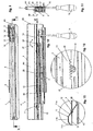
- a drawer system is shown in perspective, which has a body 1, from the interior 1b a drawer 2 is pulled out.
- the front panel 3 at the outer end of the drawer 2 closes when the drawer 2 is closed almost flush with the front end face 1a of the body 1 and is only separated from it via the gap 8 (see FIGS. 3-5).
- the tool 16 for adjusting the front panel 3 is located in the front area of the drawer 2, where also the actuating element 14 (see Figures 9-14) is arranged.
- the inclination of the plane of the front panel 3 with respect to the plane of the end face 1a of the body 1 is suitably changed.
- a height adjustment of the aperture should not be possible or at least imperceptible.
- FIG. 1 shows the drawer system according to FIG. 2 in a side view, partly in section in the lower region.
- the front panel 3 is attached to a rail system 4, which forms the connection to the body 1 on the drawer decor 6 and the carcass angle 5.
- the lifting and lowering element 11 of the diaphragm adjustment device 7 can be seen.
- Figures 3-5 are now enlarged different relative positions of the front panel 3 to the front side 1a of the body 1 is shown, with the gap 8 between them, which holds the two parts 1a and 3 in suitably adjusted case at a distance and typically at 1 to 5 mm is located.
- Figure 3 shows the ideal case (neutral position) of a perfectly adjusted gap 8, so that the planes of the front panel 3 and the end face 1a parallel to each other and therefore do not form a cutting angle 9 with each other.
- FIG. 4 shows the case where the panel 3 is inclined forward at the top so that the gap 8 'is no longer parallel but V-shaped and the planes of the front panel 3 and the front side 1a therefore do not have a positive cutting angle 9' (inclination angle ) of eg 2 degrees form each other. It is easily indicated that in this case the front panel 3 is slightly shifted downwards in comparison to FIG. The gap 8 'has become smaller in the lower region and larger in the upper region, in comparison to the gap 8 of FIG. 3.
- FIG. 5 shows the analogously reversed case of FIG. 4 with a negative cutting angle 9 "of, for example, 3.degree ..
- the front panel 3 is shifted slightly upwards in comparison to FIG. 3 and also to FIG larger and upper in the area, compared to the gap 8 of Figure 3 and also to the gap 8 'of Figure 4.
- the panel 3 touches the body 1 above, so that this represents the maximum adjustment in the direction of the negative cutting angle 9 ".
- FIGS. 6-8 now show the effect of raising and lowering the lifting and lowering element 11 for the cases of FIGS. 3-5, wherein FIG. 6 corresponds to the situation according to FIG. 3, FIG. 7 to FIG. 4 and FIG 8 of FIG. 5.
- the lifting and lowering element 11 between the drawer rail 10 of the rail system 4 and the decorative profile 6, in particular whose side wall lower part 6c is arranged.
- the lifting and lowering element 11 rests on at least two points on the drawer rail 10 and rises in at least one area roof-shaped upwards, passes through a narrow guide opening 12 in the decor 6 and the side wall lower part 6c up through, occurs in Distance therefrom through a further wider opening in the decor 6 or its side wall lower part 6c again down through and lies down again on the drawer rail 10th
- the distance between the drawer rail 10 and the decor 6 or its side wall lower part 6c is in a middle region, in FIG. 7 this distance is large, in FIG. 8 the distance is small.
- This distance is accomplished by moving the lifting and lowering element 11 in the direction of the longitudinal axis of the drawer rail 10 or the decor 6 or its side wall lower part 6c. There is automatically an increase of the decor 6 or its lower side wall portion 6c when the lifting and lowering element 11 is displaced in the direction of aperture 3, and thus the aperture 3 in FIG. 4 in the lower region approaches the end face 1a of the body 1 drawn.
- the rail system 4 is shown with decorative part 6 in a plan view, wherein the front portion of the decor 6 is shown cut away, and thus gives a view of the actuator 14.
- FIG. 10 shows a view of the section along the line XX of FIG. 9, wherein the side wall 6a, front 6b and the lower part 6c of the decorative part 6 can be seen.
- the front panel 3 not shown here is indirectly or directly attached to the decorative front wall 6b.
- the slide 15 and thus the lifting and lowering element 11 then pushes towards the front panel 3 or moves away from it, so that the distance between the drawer rail 10 and the decor 6 or side wall lower part 6c of the decor 6 is reduced or increased, whereby mainly the inclination angle 8 between the planes of the front panel 3 and the end face 1a of the body 1 changes.
- the passage of the slide 15 through the recess 30 of the decor 6 or its lower part 6c onto the drawer rail 10 can still be seen in FIG. 10, which recess 30 is arranged in front of the lifting and lowering element 11.
- FIG. 11 shows the side view from the right in the direction of arrow XI of FIG. 10, where the rail system 4 can be seen better, consisting of the aforementioned drawer rail 10, on which the decor 6 rests and rests, on which decor 6 the drawer itself attached with front 3, bottom and back.
- the drawer rail 10 is connected, as usual, via roller means to a middle rail 17, which in turn is connected by further roller means to the carcass rail 18, on which the two carcass angles are located, with which the drawer 2 is connected to the carcass 1.
- the invention can also be used in partial extracts without middle rail.
- two rail systems 4 are provided on the left and right thereof.
- the slide 15 rests partly on the upper side of the drawer rail 10 and partly on the decorative lower part 6c.
- the slide 15 consists of the actuating element 14 which is arranged in the region of the panel 3 and which is rigidly connected via a connecting element 28 to the lifting and lowering element 11 located close to the body rear wall.
- the actuating element 14 extends in the region between the front panel 3 and the beginning of the drawer rail 10, merges into the connecting element 28, which defines a virtual pivot axis 24 on the front edge to the drawer rail 10 and into the rear area of the drawer rail 10 on the decorative Lower part 6c rests.
- the distance between the drawer rail 10 and decor 6 changes at all points except on the pivot axis 24, but in particular on the lifting and lowering element 11, which is the trigger for the lifting or lowering process.
- the distance of the n extension of the longitudinal axis of the drawer rail 10 to the decor 6 changes to a small extent on the front panel 3, whereby the front panel 3 is slightly raised or lowered.
- the drawer rail 10 together with the remaining rails 17, 18 remain unaffected and in their initial position, e.g. in a horizontal position.
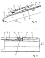
- FIG. 12 shows an enlarged detail of the penetration of the lifting and lowering element 11 through the decor 6.
- the lifting and lowering element 11 is guided tightly in the guide 12, in which case the inclined ramps of the guide 12 of the decoration 6 can then slide up and down via the guide slope 11a.
- the guide slope 11a of the slider 15 connects to the top of the plateau 11b, which fulfills only the purpose of ensuring a connection to the downwardly sloping support ramp 11c again, which is supported on the drawer rail 10.
- Figure 13 shows an enlarged detail of the support of the actuating element 14 on the lower part 6c of the decor 6.
- the teeth 19 in the side region of the actuating element 14 can be seen, in which the tool with its tip (here cross slot) engages and thereby the torque of the tool in a linear movement of the slider 15 is implemented.
- Figure 14 shows a perspective view of the displacement mechanism in the region of the actuating element 14 of the slider 15.
- the flat slider 15 is slidably mounted on the lower part 6c of the decorative side wall 6a in guide lugs 20.
- the guide tabs 20 allow sliding of the slider 15 in the direction of the longitudinal axis of the drawer rail 10, but prevent shifting transversely horizontally or optionally vertically thereto.
- the cross-hole screwdriver 16 engages from below into the lateral toothing 19 of the slider 15. With a corrugation 21 between the slider 15 and the lower part 6c, the longitudinal movement can be latched.
- Figure 15 shows how the slider 15 is bent from a band of metal or plastic to a wedge-shaped sliding piece 11, which projects through a notch 22 in the decorative base 6c upwards and which slidably rests with one side on the drawer rail 10 and with its inclined to the drawer front side (direction panel 3) wedge surface 11a on an oblique guide nose 23 of the side wall lower part 6c is supported.
- the slide movement to the rear in the direction of the rear wall of the body 1 causes a lowering of the side wall 6c and thus the drawer 2 and vice versa.
- a laterally supporting guide tab 20 is arranged on the drawer rail 10, which penetrates a slot of the wedge 11.
- Figure 16 is the enlarged side view of Figure 15 in the direction XVI, where once again the arrangement between the slider 15 between upper decor 6 and lower drawer rail 10 is illustrated.
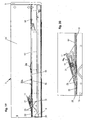
- FIGS. 17 and 18 show schematic diagrams of how the pivoting of the drawer 2 and of the decor 6 or its lower part 6c takes place by lifting / lowering the lifting and lowering element 11 and what effects this has on the stroke or lowering of the front panel 3 ,
- Figure 17 illustrates the state of the art according to nearest AT 409 067 B and DE 44014 462 A1
- Figure 18 illustrates the present invention.
- a stroke or lowering by the lifting and lowering element 11 by the amount 26 causes a pivoting of the drawer 2 and the decor 6 or its lower part 6 c about the pivot axis 24 in the pivot directions 29 by the angle 25th (For example, 5 degrees), in the positions 2 ', 6' and a pivoting of the aperture 3 by the inclination angle 9 between the aperture 3 and end face 1a of the body 1 in the position 3 '.
- the angle amount 25 corresponds to the angle of inclination 9 between the aperture 3 'and end face 1a of the body 1.
- the stroke-lowering amounts 26 and angle amounts 27 in the prior art and in the present invention are assumed to be identical.
- the amount 27 of the lifting or lowering of the aperture 3 is greater than the amount of lifting or lowering of the stroke - And lowering 11, with about a gear ratio greater than 1, depending on lever ratios, in the figures 1.25 and 1.5.
- the lifting and lowering element 11 is each a little closer to the pivot axis 24 than the diaphragm 3, so that the deflection of the lifting and lowering element 11 always has a positive gain (translation) of the deflection of the diaphragm 3 result.
- the arrangement of the prior art is completely different, since the lifting and lowering element 11 is farther away from the pivot axis 24 than the diaphragm 3, so that the deflection of the lifting and lowering element 11 is always a negative gain (reduction) the deflection of the aperture 3 result.
- the pivot axis 24 is seated on the front edge of the drawer rail 10 and the lifting and lowering 11th in the rear area of the decor 6, but not at the maximum rear, so that a reduction ratio of about 0.3 results.
- 3 mm Height excursion 24 on the lifting and lowering element 11 then result in about 1 mm height deflection 27 on the diaphragm 3 ', wherein in the prior art, about 4 mm height deflection 27 would adjust to the diaphragm 3', that is 4 times as much.
- the unwanted height deflection 27 does not play a significant role and can therefore be neglected.
- a simple and rapid tilt adjustment of the angle 9 of the diaphragm 3 is possible, with only one aperture adjusting device 7, which leads to reduced manufacturing and assembly costs.
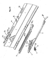
- FIG. 19 shows a side view of a drawer with another embodiment of a diaphragm adjustment device, wherein FIG. 20 shows an enlarged view of the lifting and lowering element 11 of the diaphragm adjustment device according to FIG. 19.
- FIG. 20 shows an enlarged view of the lifting and lowering element 11 of the diaphragm adjustment device according to FIG. 19.
- An exploded perspective view of the diaphragm adjustment device according to FIG. 19 is shown in FIG.
- the individual parts of the aperture adjustment can be seen, which consists of an adjusting element 31 in the form of a screw with gear 35, a slider 15 with lifting and lowering 11 with guide ramp 11a, a strip-shaped rocker 32 with guide wings 32a and guide track 32b , and from a notch 22 from the lower part 6c of the decorative profile 6, with guide lugs 23rd
- the lifting and lowering element 11 now engages from below (FIG. 21) into the longitudinal slot of the guide track 32b and is displaceably guided in its length. Furthermore, the lifting and lowering element 11 passes through the notch 22 on the upper side of the lower part 6 c of the decorative profile 6 and the guide ramp 11 a is guided between the guide lugs 23 on the notch 22.
- the rocker 32 is in this case between the slider 15 and the decorative base 6c and the wings 32a of the rocker 32 pass through for lateral stabilization openings 36 in the decorative base 6c.
- a front Bogenendteil 38 passes through a further opening 37 in the decorative lower part 6c and rests on the surface of the decorative base 6c and can be moved longitudinally there, so that the Bogenendteil 38 is a guiding and supporting means of the slider 15 and the rocker 32.
- the slider 15 shown in Fig. 21 and the rocker 32 are fixed by the leadership of the guide ramp 11a between the guide lugs 23 on the notch 22 on the decorative base 6c, but also by the support of the Bogenendteils 38 on the decorative base 6c.
- the adjusting element 31 is stationary and rotatable on the inner side of the decorative profile 6 (bottom 6c) and engages with its pin 39 in the recess 40 of a tab 41 at the edge of the notch 22 a. With its gear 35, the adjusting element 31 engages in the toothing 19 of the lifting and lowering element 11, which is designed in particular as a plastic part.
- the lifting and lowering element 11 of the slider 15 engages in a guide track 32b of the rocker 32 and can be moved axially in this.
- the rocker 32 is guided with at least two wings 32a in the lower part 6c of the decor 6 and in particular formed as a sheet-metal part.
- the position of the actuating element 14, 31 is possible not only in the front region of the drawer (FIGS. 1-18), but also in the rear region (FIGS. 19-21).
- the actuator 31 in the rear part of the drawer is reached with the drawer pulled over the interior, so that the drawer must be emptied before.
Abstract
Description
Die Erfindung betrifft eine Blendeneinstellvorrichtung nach dem Oberbegriff der unabhängigen Ansprüche.The invention relates to a diaphragm adjusting device according to the preamble of the independent claims.
Die AT 399 086 B zeigt eine Verstellvorrichtung für Schubladenblenden bei der die Neigung der Blende um ein Maß abweichend von der Senkrechten durch längeneinstellbare Relinge einstellbar ist. Diese Art der Neigungseinstellung ist nur möglich, wenn die Schublade mit Relingen versehen ist.The AT 399 086 B shows an adjusting device for drawer panels in which the inclination of the diaphragm is adjustable by a measure deviating from the vertical by adjustable length railings. This type of tilt adjustment is only possible if the drawer is provided with railings.
Nachteil dieser Ausführungsform ist die Voraussetzung von Relingen wie erwähnt, und dass entweder zwischen der Zarge und der Blende ein konischer Spalt entsteht oder der Anschraubwinkel zwangsweise verbogen wird.Disadvantage of this embodiment is the requirement of relining as mentioned, and that either a conical gap between the frame and the aperture or the Anschraubwinkel is forcibly bent.
Die DE 38 43 658 A1 zeigt eine Blendenbefestigung bei welcher ebenfalls die Neigung der Blende verstellt wird, jedoch mit einem verschiebbaren Keil. Der sich dabei bildende konische Spalt muss mit einer speziellen Abdeckung unsichtbar und vor Verschmutzung geschützt sein. Ein Verbiegen des Anschraubwinkels kann gewollt sein oder durch Lösen der Befestigungsschrauben weitest gehend verhindert werden.
Die AT 409 067 B zeigt eine der Erfindung schon näher gelegene Vorrichtung zur Höhen- und Neigungsverstellung der gesamten Schublade mit Frontblende, welche Vorrichtung zwischen Schublade und Schubladenschiene angeordnet ist. Hier sind im vorderen Bereich der Schublade zum Höhenausgleich verschiebbare Keile vorgesehen, die gleichzeitig auch eine Neigungsverstellung der Frontplatte der Schublade bewirken. Im hinteren Bereich der Schublade sind Mittel zur Vertikalverstellung zum Anheben der Schublade vorgesehen, die ebenfalls auch eine Neigungsverstellung der Frontplatte der Schublade bewirken. Wie die Keile auf beiden Seiten verschoben werden, ist hier nicht gezeigt.The AT 409 067 B shows an already closer to the invention device for height and tilt adjustment of the entire drawer with front panel, which device is arranged between drawer and drawer rail. Here, slidable wedges are provided in the front area of the drawer for height adjustment, which at the same time cause a tilt adjustment of the front panel of the drawer. In the rear of the drawer means for vertical adjustment to lift the drawer are provided, which also cause a tilt adjustment of the front panel of the drawer. How the wedges are moved on both sides is not shown here.
Um die Höhe der Schublade nach der Schubladenneigungserstellung zu korrigieren, müssen aufwendige Verschiebevorrichtungen der Keile vorhanden sein. Diese aufwendigen Verschiebevorrichtungen müssen auch dann vorhanden sein, wenn die Höhenpositionen der Blenden zuerst eingestellt werden und anschließend das Fugenbild durch eine Schubladen-Blendeneigung korrigiert wird. Ein gravierender Nachteil ist, dass die Neigungsverstellung sich hinter der Schublade befindet. Zur Betätigung muss die Schublade aus dem Korpus herausgezogen werden. Bis die Blende angepasst ist, kann man die Lade einige Male herausziehen und hineinschieben. Die Verstellvorrichtung ist also kompliziert und zeitraubend zu betätigen und zudem relativ teuer in der Herstellung.In order to correct the height of the drawer after the drawer tilting preparation, complicated displacement devices of the wedges must be present. These complicated displacement devices must also be present when the height positions of the panels are set first and then the joint pattern is corrected by a drawer aperture inclination. A serious disadvantage is that the tilt adjustment is located behind the drawer. To operate, the drawer must be pulled out of the carcass. Until the panel is adjusted, you can pull out the drawer a few times and push it in. The adjustment is so complicated and time-consuming to operate and also relatively expensive to manufacture.
Die DE 44014 462 A1 zeigt eine Höhenverstellung von Schubladen mit Frontblende, deren Vorrichtung zwischen Schublade und Schubladenschiene angeordnet ist. Im vorderen Schublädenbereich kann mit einem in geneigt verlaufenden Führungsschlitzen verschieblichen Schieber die Schublade mit Blende angehoben werden oder auch (von einer Mittellage) abgesenkt werden. Nachteil dabei ist, dass die durch die Höhenverstellung gleichzeitig bewirkte Spaltveränderung (Tiefe und Neigung) nicht mehr ausgeglichen werden kann, wozu eine weitere Einstellvorrichtung benötigt würde.DE 44014 462 A1 shows a height adjustment of drawers with front panel, whose device is arranged between drawer and drawer rail. In the front drawer area, the drawer with cover can be raised or lowered (from a central position) by means of a slide displaceable in inclined guide slots. Disadvantage is that the same time caused by the height adjustment gap change (depth and inclination) can not be compensated, what would require a further adjustment.
Im Übrigen haben die beiden letzt genannten Vorrichtungen den Nachteil, dass ein Übersetzungsverhältnis von ca. 1.25 bis 1,5 vorhanden ist, so dass bei 1 mm Verstellung der Höhe an der Höhenverstellvorrichtung etwa 1,25 bis 1,5 mm Höhenverstellung der Frontblende der Schublade erreicht wird. Durch die dort gezeigten Hebelverhältnisse ergibt sich, dass sich die Frontblende pro Grad Winkeländerung der Schublade etwa um 0,25 mm ändert, was doch erheblich ist, bei einzustellenden Winkeln von +/- 10 Winkelgraden, die zu einer maximalen Abweichung von 2,5 mm führen, was in jedem Fall ohne Kompensation zu viel ist, um sich optisch nicht bemerkbar zu machen.Incidentally, the two latter devices have the disadvantage that a transmission ratio of about 1.25 to 1.5 is present, so that at 1 mm adjustment of the height of the height adjustment about 1.25 to 1.5 mm height adjustment of the front panel of the drawer is reached. The leverage ratios shown there result in the front panel changing by about 0.25 mm per degree of change in the angle of the drawer, which is considerable, with angles of +/- 10 degrees to be set resulting in a maximum deviation of 2.5 mm lead, which is in any case too much without compensation, to make itself visually not noticeable.
Aufgabe ist es, ausgehend vom oben genannten Stand der Technik eine kostengünstige Blendeneinstellvorrichtung bereit zu stellen, welche ein einfaches und schnelles Einstellen des Neigungswinkels zwischen der vertikalen Ebene der Frontblende der Schublade und der vertikalen Ebene der vorderen Stirnseite des Möbelkorpus ermöglicht.The object is, starting from the above-mentioned state of the art, to provide a cost-effective diaphragm adjustment device which enables a simple and rapid adjustment of the angle of inclination between the vertical plane of the front panel of the drawer and the vertical plane of the front end side of the furniture carcass.
Gelöst wird die gestellte Aufgabe durch die Merkmale der unabhängigen Ansprüche.The object is achieved by the features of the independent claims.
Wesentlich dabei ist, dass die Blendeneinstellvorrichtung unmittelbar oder mittelbar zwischen der Schublade und der Schubladenschiene über eine Hub- und Senkvorrichtung mit Hub- und Senkelement derart wirkt, dass eine Verschwenkung der Schublade und damit der Blende um eine Schwenkachse ermöglicht wird, wobei die Schwenkachse zwischen der Frontblende und dem Hub- und Senkelement verläuft und der Abstand zwischen Schwenkachse und der Frontblende etwa gleich groß oder kleiner ist als der Abstand zwischen der Schwenkachse und dem Hub- und Senkelement.It is essential that the Blendeneinstellvorrichtung directly or indirectly between the drawer and the drawer rail via a lifting and lowering device with lifting and lowering element acts such that a pivoting of the drawer and thus the aperture is made possible about a pivot axis, wherein the pivot axis between the Front panel and the lifting and lowering element extends and the distance between the pivot axis and the front panel is about the same size or smaller than the distance between the pivot axis and the lifting and lowering.
Dabei ist bevorzugt, dass die Schwenkachse möglichst nahe an der Frontblende und/oder das Hub- und Senkelement möglichst weit von der Schwenkachse entfernt vorgesehen ist.It is preferred that the pivot axis is provided as close as possible to the front panel and / or the lifting and lowering as far away from the pivot axis.
Wesentlicher Vorteil hierbei ist, dass nach der Blendenkorrektur in der Neigung kein Ausgleich in der Höhe mehr erforderlich ist. Weiterer Vorteil ist, dass eine Einstellung des Neigungswinkels möglich ist, ohne dass ein konischer Spalt zwischen Dekor-Seitenwand-Stimseite und der Blende und ohne dass Verbiegung der Seitenwänd-Stirnseite entsteht, wie teilweise beim Stand der Technik. Ebenso ist eine einfachste Bedienung der Blendeneinstellvorrichtung am vorderen oder hinteren Schubladenteil ohne Entfernen der Schublade möglich.The main advantage here is that after the aperture correction in the slope no compensation in height is required more. Another advantage is that an adjustment of the angle of inclination is possible without a conical gap between the decorative side wall end face and the diaphragm and without bending the side wall end face arises, as partially in the prior art. Likewise, the simplest operation of the diaphragm adjustment device on the front or rear drawer part is possible without removing the drawer.
Ein Ausgleich der Höhe der Blende nach Einstellen des Neigungswinkels ist deshalb nicht mehr nötig, da kein Übersetzungsverhältnis der Höhenauslenkung des Hub- und Senkelements zur Höhenauslenkung der Frontblende wie beim Stand der Technik mehr vorhanden ist, sondern ein Untersetzungsverhältnis, bei gleichem Auslenkwinkel der Schublade bzw. Neigungswinkel der Frontblende. Während beim eingangs zitierten Stand der Technik gemäß den Figuren das Übersetzungsverhältnis bei minimal 1,25 liegt, jedoch naturgemäß nie unter 1 sein kann, liegt das Untersetzungsverhältnis der Erfindung auf Grund der speziellen Konstellation zwischen Drehpunkt, Hub- und Senkelement und Blende bei unter 1, z.B. bei 0,3. Dadurch ergibt sich, dass sich die Frontblende pro Grad Winkeländerung der Schublade lediglich etwa 0,05 mm ändert, also lediglich 20% des Wertes des Standes der Technik. Durch geeignete Veränderung der Abstände zwischen Drehpunkt, Hub- und Senkelement und Blende.kann dieser Wert noch weiter Richtung Null geführt werden. Wichtig für die Erfindung ist aber ein Untersetzungsverhältnis von kleiner (oder gleich) 1, welches bevorzugt so klein als möglich gehalten wird, typisch aber bei etwa 0.25 liegt. Die Untersetzung von 0,25 bedeutet, dass für 1 Grad Winkeländerung der Schublade und der daran befestigten Blende eine Höhenänderung des Hub- und Senkelements von z.B. 2 mm nötig ist und damit verbunden lediglich eine (nicht erwünschte) Höhenänderung der Blende um ca. 0,5 mm einhergeht. Beim Stand der Technik mit Übersetzung größer 1 wäre hier eine Höhenänderung der Blende von 2,5 mm zu verzeichnen, was in jedem Fall durch zusätzliche Vorrichtungen ausgeglichen werden müsste.A compensation of the height of the aperture after adjusting the inclination angle is therefore no longer necessary, since no ratio of the height deflection of the lifting and lowering element for height deflection of the front panel as in the prior art is no longer present, but a reduction ratio, at the same deflection angle of the drawer or Tilt angle of the front panel. While in the cited prior art according to the figures, the transmission ratio is at least 1.25, but naturally can never be less than 1, the reduction ratio of the invention due to the special constellation between fulcrum, lifting and lowering and aperture at less than 1, eg at 0.3. As a result, the front panel only changes by about 0.05 mm per degree of angle change of the drawer, ie only 20% the value of the prior art. By appropriately changing the distances between the pivot point, the lifting and lowering element and the diaphragm, this value can be guided further towards zero. But important for the invention is a reduction ratio of less than (or equal to) 1, which is preferably kept as small as possible, but is typically about 0.25. The reduction of 0.25 means that for 1 degree angle change of the drawer and the attached panel a height change of the lifting and lowering element of
Für ein Untersetzungsverhältnis nach der vorliegenden Erfindung ist es also nötig, dass der Abstand der Blende zur Schwenkachse der Schublade bzw. des Dekors auf der Schubladenschiene kleiner ist oder höchstens gleich groß, als der Abstand des Hub- und Senkelements zur Schwenkachse, was nur möglich ist, wenn sich die Schwenkachse zwischen Blende und Hub- und Senkelement befindet.For a reduction ratio according to the present invention, it is therefore necessary that the distance of the diaphragm to the pivot axis of the drawer or the decor on the drawer rail is smaller or at most equal to the distance of the lifting and lowering element to the pivot axis, which is only possible when the pivot axis between the aperture and lifting and lowering element is located.
Weitergehende Ausgestaltungen der Erfindung sind in den Unteransprüchen definiert.Further embodiments of the invention are defined in the subclaims.
Es ist bevorzugt, dass die Schwenkachse auf der Schubladenschiene liegt und das Hub- und Senkelement insbesondere im hinteren Bereich des Schubladendekors, insbesondere auf dessen Unterteil.It is preferred that the pivot axis lies on the drawer rail and the lifting and lowering element in particular in the rear region of the drawer decoration, in particular on its lower part.
Hierbei ist bevorzugt, dass die Hub- und Senkvorrichtung einen Schieber beinhaltet, der das Hub- und Serikelement, ein Verbindungselement und ein Betätigungselement für das Hub- und Senkelement enthält, wobei das Hub- und Senkelement im hinteren Bereich der Schublade angeordnet ist, welches mit einem im vorderen oder auch im hinteren Bereich der Schublade angeordneten Betätigungselement für das Hub- und Senkelement über das Verbindungselement verbunden ist.It is preferred that the lifting and lowering device includes a slide containing the lifting and serial element, a connecting element and an actuating element for the lifting and lowering, wherein the lifting and lowering element is arranged in the rear region of the drawer, which with an arranged in the front or in the rear region of the drawer actuator for the lifting and lowering is connected via the connecting element.
Vorteil hierbei ist, dass durch die Anordnung im vorderen Bereich der Schublade des Betätigungselements für das Hub- und Senkelement ein einfaches und bequem zugängliches Betätigen des Hub- und Senkelements im hinteren Bereich der Schublade und damit der Einstellung der Frontblende der Schublade im Neigungswinkel möglich ist. Die Erfindung trennt also räumlich die Funktionen des Betätigens des Hub- und Senkelements und des Heben und Senkens d.h. Einstellen der Neigung der Schublade und der damit verbundenen Blende.The advantage here is that the arrangement in the front region of the drawer of the actuator for the lifting and lowering a simple and convenient accessible actuation of the lifting and lowering element in the rear of the drawer and thus the adjustment of the front panel of the drawer in the tilt angle is possible. The invention thus spatially separates the functions of operating the lifting and lowering element and the lifting and lowering, i. Adjust the inclination of the drawer and the associated panel.
Insbesondere ist hierbei das Betätigungselement für das Hub- und Senkelement im vorderen Bereich an der Schublade selbst oder dessen Dekorteil angeordnet, und das Hub- und. Senkelement im hinteren Bereich an der Schubladenschiene. Dabei durchdringt der Schieber die Schublade selbst oder dessen Dekorteil auf seinem Weg in den hinteren Bereich der Schublade.In particular, in this case the actuating element for the lifting and lowering element in the front area of the drawer itself or its decorative part is arranged, and the lifting and. Lowering element in the rear area on the drawer rail. The slide penetrates the drawer itself or its decorative part on its way to the rear of the drawer.
Hierzu wird es bevorzugt, dass die Auflageflächen der Schublade selbst oder dessen Dekorteil und der Schubladenschiene für das Hub- und Serikelement und dessen Betätigungselement etwa horizontal liegen und nach oben zeigen, was jedoch nicht zwingend nötig ist, da auch vertikale Flächen oder nach unten zeigende horizontale Flächen ein Auflager hierfür bilden können, wobei jedoch in jedem Fall dann zusätzliche Halte- oder Führungseinrichtungen nötig sind.For this purpose, it is preferred that the bearing surfaces of the drawer itself or its decorative part and the drawer rail for the lifting and serial element and its actuator are approximately horizontal and pointing upwards, which is not absolutely necessary, as well as vertical surfaces or downward horizontal Surfaces can form a support for this, but in any case then additional holding or guiding devices are necessary.
Insbesondere ist das Hub- und Senkelement und dessen Betätigungselement in Form eines Schiebers aus Flachmaterial ausgebildet, welcher sich vom vorderen bis in den hinteren Führungsschienenbereich erstreckt und vom vorderen bis über den Mittelbereich auf dem einem, insbesondere dem horizontalen Schenkel des Seitenwand-Unterteils verschiebbar gelagert ist, und im hinteren Bereich sich auf der Schubladenschiene abstützt, wobei das Ende des Schiebers zu einem keilförmigen Schiebstück ausgeformt ist.In particular, the lifting and lowering element and its actuating element in the form of a slider made of flat material, which extends from the front to the rear guide rail area and is slidably mounted from the front to about the central region on the one, in particular the horizontal leg of the side wall lower part , And in the rear area is supported on the drawer rail, wherein the end of the slider is formed into a wedge-shaped sliding piece.
Der Schieber ist dabei bevorzugt in seiner Längserstreckung vorzugsweise ein Stück vor dem Hub- und Senkelement abgekröpft und ragt durch eine Ausnehmung im horizontalen Schenkel des Schubladen-Unterteils zur Auflage auf der Schubtadenschiene.The slider is preferably preferably bent in its longitudinal extent a piece in front of the lifting and lowering and protrudes through a recess in the horizontal leg of the drawer base to rest on the Schubtadenschiene.
Die erfindungsgemäße Schieber mit hinterem Hub- und Senkelement und vorderem Betätigungselement für das Hub- und Senkelement kann hierbei verschiedene Formen aufweisen, insbesondere ist aber das Hub- und Senkelement mit dem Betätigungselement einteilig verbunden und einstückig aus dem selben Material hergestellt, z.B. aus Flachstahl, aus Draht oder aus einem streifenförmigem Kunsfstoffmaterial.The slide according to the invention with rear lifting and lowering element and front actuating element for the lifting and lowering element may in this case have different shapes, but in particular the lifting and lowering element is integrally connected to the actuating element and made in one piece from the same material, e.g. made of flat steel, wire or a strip-shaped Kunsfstoffmaterial.
Das Betätigungselement und das Hub- und Senkelement der Blendeneinstellvorrichtung können jedoch in einer anderen Ausführungsform der Erfindung als zwei oder mehrere separate Teilen hergestellt werden und miteinander verbunden werden.However, in another embodiment of the invention, the actuator and the lifting and lowering element of the diaphragm adjusting device may be manufactured as two or more separate parts and connected together.
Das Betätigungselement der Blendeneinstellvorrichtung besitzt insbesondere eine Verzahnung, in die ein Werkzeug (z.B. Schraubendreher) bei der Einstellung durch einen Monteur eingreift und somit eine Verschiebung des Betätigungselements in Längsrichtung der Schienen und damit ein Heben oder Senken des Hub- und Senkelements bewirkt wird. Damit wird der Abstand zwischen Schublade/Dekor und Schubladenschiene verändert und damit der Neigungswinkel der mit der Schublade fest verbundenen Frontblende im Bezug zur vertikalen Vorderseite des Möbelkorpus verändert. Zwangsläufig wird hierdurch auch in geringem Maße die Höhe der Frontblende im Bezug zum Möbelkorpus verändert, was jedoch nur in unmerklichem Ausmaß geschieht.In particular, the actuator of the diaphragm adjusting device has a toothing in which a tool (for example a screwdriver) engages in the setting by a fitter and thus causes a displacement of the actuating element in the longitudinal direction of the rails and thus a lifting or lowering of the lifting and lowering element. This changes the distance between the drawer / drawer and the drawer rail and thus changes the angle of inclination of the front panel fixed to the drawer relative to the vertical front of the cabinet. Inevitably, the height of the front panel is changed in relation to the furniture body to a small extent, but this happens only to an insensible extent.
Die Verzahnung ist vorteilhaft in der Seitenwand des Betätigungselements vorgesehen, wobei natürlich auch eine verzahnte längliche Ausnehmung (Langloch) im Betätigungselement vorhanden sein kann, in das dann das Werkzeug eingreift. Beliebige ändere äquivalente Mechanismen hierfür sollen durch die Erfindung geschützt sein. Natürlich kann das Werkzeug selbst mindestens teilweise Teil des Betätigungselements sein und an der Blendeneinstellyorrichtung verbleiben, auch wenn der Einstellvorgang beendet ist. So kann z.B. eine Verlängerung des externen Werkzeugs ermöglicht werden.The toothing is advantageously provided in the side wall of the actuating element, of course, a toothed elongated recess (slot) may be present in the actuating element, in which then engages the tool. Any other equivalent mechanisms for this purpose should be protected by the invention. Of course, the tool itself may be at least partially part of the actuator and remain on the shutter setting device, even when the adjustment operation is completed. Thus, e.g. extension of the external tool.
Der gesamte Schieber oder nur Teile davon kann in Führungslappen auf der Schubladenschiene und/oder der Schublade bzw. dessen Dekorprofil geführt werden, welche Führungslappen eine horizontale und ggf. auch eine vertikale Führung bilden, die eine Bewegung in der Längsachse der Schienen aber immer noch ermöglichen, nicht jedoch quer dazu.The entire slider or only parts thereof can be guided in guide lugs on the drawer rail and / or the drawer or its decorative profile which guide tabs form a horizontal and possibly also a vertical guide, but still allow movement in the longitudinal axis of the rails, but not across it.
Zur Beibehaltung der einmal eingestellten Relativstellung zwischen Schublade/Dekor und Schubladenschiene ist die Blendeneinstellvorrichtung mit einer Rasteinrichtung ausgestattet, insbesondere in Form von selbst hemmenden Riffelungen, die ein unbeabsichtigtes Verschieben der Blendeneinstellvorrichtung verhindern. Hierzu ist die Riffelung insbesondere zwischen dem Schieber und der Schublade bzw. deren Dekor vorgesehen und insbesondere auf der Schublade bzw. deren Dekor angeordnet, insbesondere im Bereich des Betätigungselements des Hub- und Senkelements. Zusätzlich kann auch als Gegenverzahnung auf dem Schieber eine gleichartige Riffelung vorhanden sein. Die Riffelung ist dabei quer und/oder schräg zur Verschieberichtung des Schiebers angeordnet.To maintain the once set relative position between drawer / decor and drawer rail the Blendeneinstellvorrichtung is equipped with a locking device, in particular in the form of self-locking corrugations that prevent unintentional movement of Blendeneinstellvorrichtung. For this purpose, the corrugation is provided in particular between the slide and the drawer or their decor and arranged in particular on the drawer or its decor, in particular in the region of the actuating element of the lifting and lowering element. In addition, a similar corrugation may be present as a counter toothing on the slide. The corrugation is arranged transversely and / or obliquely to the direction of displacement of the slider.
Damit der Schieber der Blendeneinstellvorrichtung beim Bewegen in Längsrichtung der Schienen nicht aus seiner Funktionsstellung herausgezogen werden kann, sind entsprechende Anschlagbegrenzungen auf der Schublade/Dekor und/oder auf der Schubladenschiene vorgesehen.Thus, the slider of the aperture setting when moving in the longitudinal direction of the rails can not be pulled out of its functional position, corresponding stop limits on the drawer / decor and / or on the drawer rail are provided.
Im folgenden wird die Erfindung anhand von beispielhaften Zeichnungen näher erläutert, aus denen weitere Merkmale, Vorteile und Anwendungen hervorgehen.In the following the invention will be explained in more detail with reference to exemplary drawings, from which further features, advantages and applications emerge.
Es zeigen:
- Figur 1:
- eine Schublade mit speziell hoher Blende im Korpus. Das im hinteren Schubladenteil befindliche keilförmige Schiebestück ist zu sehen;
- Figur 2:
- eine perspektivisch dargestellte Schublade mit Verstellwerkzeug am Ort der Verstellung im vorderen Schubladenteil;
Figur - eine Vergrößerung des linken Frontbereichs nach Figur 1;
- Figur 3:
- den korrekt eingestellten Spalt zwischen der Blende und dem Korpus;
- Figur 4:
- eine erste konische Spalt-Version mit positivem Neigungswinkel zwischen Blende und dem Korpus;
- Figur 5:
- eine zweite konische Spalt-Version mit negativem Neigungswinkel zwischen Blende und dem Korpus;
- Figur 6:
- die Stellung des keilförmigen Schiebestückes passend zu Figur 3;
- Figur 7:
- Stellung des keilförmigen Schiebestückes passend zu Figur 4;
- Figur 8:
- Stellung des keilförmigen Schiebestückes passend zu Figur 5;
- Figur 9:
- eine Draufsicht der Dekor-Seitenwand mit der Verstellvorrichtung im vorderen Bereich der Seitenwand;
- Figur 10:
- eine Seitenansicht im Schnitt entlang der Linie X-X der Figur 9 mit Dekor, Schienensystem und Verstellvorrichtung;
- Figur 11:
- die Seitenansicht in Richtung des Pfeils XI der Figur 10;
- Figur 12:
- ein vergrößertes Detail des Hub- und Senkelements des Schiebers;
- Figur 13:
- ein vergrößertes Detail des Betätigungselements für das Hub- und Senkelement im Zustand des Eingriffs eines Schraubendrehers in die Verzahnung des Betätigungselements des Schiebers;
- Figur 14:
- eine perspektivische Ansicht des Verschiebemechanismus im Bereich des Betätigungselements für das Hub- und Senkelement des Schiebers;
- Figur 15:
- eine perspektivische Ansicht des Verschiebemechanismus im Bereich des Hub- und Senkelements des Schiebers;
- Figur 16:
- die Seitenansicht in Pfeilrichtung XVI der
Figur 15; - Figur 17:
- eine Prinzipskizze der Verschwenkwege und -winkel der Schublade und der Schubladenfront beim Stand der Technik;
- Figur 18:
- eine Prinzipskizze der Verschwenkwege und -winkel der Schublade und der Schubladenfront nach der vorliegenden Erfindung.
- Figur 19:
- Seitenansicht einer Schublade mit einer anderen Ausführungsform einer Blendenverstellvorrichtung;
- Figur 20:
- vergrößerte Ansicht des Hub- und Senkelements der Blendenverstellvorrichtung nach Figur 19;
- Figur 21:
- perspektivische Explosionsdarstellung einer vergrößerten Ansicht der Blendenverstellvorrichtung nach Figur 19.
- FIG. 1:
- a drawer with a special high aperture in the body. The wedge-shaped sliding piece located in the rear drawer part can be seen;
- FIG. 2:
- a perspective drawer with adjusting tool at the location of the adjustment in the front drawer part;
- FIGS. 3, 4 and 5:
- an enlargement of the left front portion of Figure 1;
- FIG. 3:
- the correctly adjusted gap between the panel and the body;
- FIG. 4:
- a first conical gap version with a positive angle of inclination between the panel and the body;
- FIG. 5:
- a second conical gap version with a negative angle of inclination between the panel and the body;
- FIG. 6:
- the position of the wedge-shaped sliding piece suitable for Figure 3;
- FIG. 7:
- Position of the wedge-shaped sliding piece suitable for Figure 4;
- FIG. 8:
- Position of the wedge-shaped sliding piece suitable for Figure 5;
- FIG. 9:
- a plan view of the decorative side wall with the adjustment in the front region of the side wall;
- FIG. 10:
- a side view in section along the line XX of Figure 9 with decor, rail system and adjusting device;
- FIG. 11:
- the side view in the direction of the arrow XI of Figure 10;
- FIG. 12:
- an enlarged detail of the lifting and lowering of the slider;
- FIG. 13:
- an enlarged detail of the operating element for the lifting and lowering in the state of engagement of a screwdriver in the toothing of the actuating element of the slider;
- FIG. 14:
- a perspective view of the displacement mechanism in the region of the actuating element for the lifting and lowering of the slider;
- FIG. 15:
- a perspective view of the displacement mechanism in the region of the lifting and lowering of the slider;
- FIG. 16:
- the side view in the direction of arrow XVI of Figure 15;
- FIG. 17:
- a schematic diagram of Verschwenkwege and angles of the drawer and the drawer front in the prior art;
- FIG. 18:
- a schematic diagram of the Verschwenkwege and angles of the drawer and the drawer front according to the present invention.
- FIG. 19:
- Side view of a drawer with another embodiment of a diaphragm adjustment device;
- FIG. 20:
- enlarged view of the lifting and lowering of the aperture adjusting device of Figure 19;
- FIG. 21:
- is an exploded perspective view of an enlarged view of the diaphragm adjustment device of Figure 19.
In Figur 2 ist perspektivisch ein Schubladensystem dargestellt, die einen Korpus 1 aufweist, aus dessen Innenraum 1b eine Schublade 2 ausgezogen ist. Die Frontblende 3 am äußeren Ende der Schublade 2 schließt bei geschlossener Schublade 2 nahezu bündig mit der vorderen Stirnseite 1a des Korpus 1 ab und ist nur über den Spalt 8 (siehe Figuren 3-5) davon getrennt. Das Werkzeug 16 zur Verstellung der Frontblende 3 ist im vorderen Bereich der Schublade 2 eingezeichnet, wo auch das Betätigungselement 14 (siehe Figuren 9-14) angeordnet ist. Durch Betätigen (hier: Drehen) des Werkzeugs 16 wird die Neigung der Ebene der Frontblende 3 im Bezug auf die Ebene der Stirnseite 1a des Korpus 1 geeignet verändert. Eine Höhenverstellung der Blende soll möglichst nicht oder zumindest nur unmerklich erfolgen.In Figure 2, a drawer system is shown in perspective, which has a
Figur 1 zeigt das Schubladensystem nach Figur 2 in einer Seitenansicht, teilweise im Schnitt im unteren Bereich. Hier ist erkennbar, dass die Frontblende 3 an einem Schienensystem 4 befestigt ist, welches die Verbindung zum Korpus 1 über das Schubladen-Dekor 6 und die Korpuswinkel 5 bildet. Im hinteren Bereich des Schubladensystems von Figur 1, also auf der anderen Seite der Frontblende 3 im Schienensystem 4 ist das Hub- und Senkelement 11 der Blendenverstellvorrichtung 7 zu sehen.FIG. 1 shows the drawer system according to FIG. 2 in a side view, partly in section in the lower region. Here it can be seen that the
In den Figuren 3-5 sind nun vergrößert verschiedene Relativstellungen der Frontblende 3 zur Stirnseite 1a des Korpus 1 dargestellt, wobei dazwischen sich der Spalt 8 befindet, der die beiden Teile 1a und 3 im geeignet eingestellten Fall auf Abstand hält und typisch bei 1 bis 5 mm liegt.In Figures 3-5 are now enlarged different relative positions of the
Figur 3 zeigt den Idealfall (Neutralstellung) eines perfekt eingestellten Spaltes 8, so dass die Ebenen der Frontblende 3 und der Stirnseite 1a parallel zueinander verlaufen und daher keinen Schnittwinkel 9 untereinander bilden.Figure 3 shows the ideal case (neutral position) of a perfectly adjusted
Figur 4 zeigt den Fall, dass die Blende 3 oben nach vorne geneigt ist, so dass der Spalt 8' nicht mehr parallel, sondern V-förmig ist und die Ebenen der Frontblende 3 und der Stirnseite 1a daher keinen positiven Schnittwinkel 9' (entspricht Neigungswinkel) von z.B. 2 Grad untereinander bilden. Es ist leicht angedeutet, dass in diesem Fall die Frontblende 3 im Vergleich zu Figur 3 leicht nach unten verschoben ist. Der Spalt 8' ist im unteren Bereich kleiner und im oberen Bereich größer geworden, im Vergleich zum Spalt 8 der Figur 3.FIG. 4 shows the case where the
Figur 5 zeigt den analog umgekehrten Fall von Figur 4 mit einem negativen Schnittwinkel 9" von z.B. 3 Grad. In diesem Fall die Frontblende 3 im Vergleich zu Figur 3 und auch zu Figur 4 leicht nach oben verschoben. Der Spalt 8" ist im unteren Bereich größer und im oberen Bereich kleiner geworden, im Vergleich zum Spalt 8 von Figur 3 und auch zum Spalt 8' der Figur 4. Die Blende 3 berührt den Korpus 1 oben, so dass dies die maximale Verstellung in Richtung des negativen Schnittwinkels 9" darstellt.5 shows the analogously reversed case of FIG. 4 with a
Die Figuren 6-8 stellen nun die Wirkung des Hebens und Senkens des Hub- und Senkelements 11 für die Fälle der Figuren 3-5, wobei die Figur 6 der Situation nach der Figur 3 entspricht, die Figur 7 der nach Figur 4 und die Figur 8 der nach Figur 5.FIGS. 6-8 now show the effect of raising and lowering the lifting and lowering
Nach den Figuren 6-8 ist das Hub- und Senkelement 11 zwischen der Schubladenschiene 10 des Schienensystems 4 und dem Dekorprofil 6, insbesondere dessen Seitenwand-Unterteil 6c angeordnet. Das Hub- und Senkelement 11 liegt dabei an mindestens zwei Stellen auf der Schubladenschiene 10 auf und erhebt sich in mindestens einem Bereich dachförmig nach oben, tritt durch eine schmale Führungsöffnung 12 im Dekor 6 bzw. dessen Seitenwand-Unterteil 6c nach oben hindurch, tritt im Abstand davon durch eine weitere breitere Öffnung im Dekor 6 bzw. dessen Seitenwand-Unterteil 6c wieder nach unten hindurch und legt sich wieder auf die Schubladenschiene 10.According to Figures 6-8, the lifting and lowering
In Figur 6 ist der Abstand zwischen der Schubladenschiene 10 und dem Dekor 6 bzw. dessen Seitenwand-Unterteil 6c in einem mittleren Bereich, in Figur 7 ist dieser Abstand groß, in Figur 8 ist der Abstand klein. Dieser Abstand wird durch Verschieben des Hub- und Senkelements 11 in Richtung der Längsachse der Schubladenschiene 10 bzw. des Dekor 6 bzw. dessen Seitenwand-Unterteil 6c bewerkstelligt. Es erfolgt automatisch eine Anhebung des Dekors 6 bzw. dessen Seitenwand-Unterteil 6c, wenn das Hub- und Senkelement 11 in Richtung Blende 3 verschoben wird, und damit wird die Blende 3 gemäß Figur 4 im unteren Bereich an die Stirnseite 1a des Korpus 1 heran gezogen. Analog umgekehrt erfolgt automatisch eine Absenkung des Dekors 6 bzw. dessen Seitenwand-Unterteil 6c, wenn das Hub- und Senkelement 11 von der Blende 3 weg gerichtet verschoben wird, und damit wird die Blende 3 gemäß Figur 5 im unteren Bereich von der Stirnseite 1a des Korpus 1 weg gedrückt.In FIG. 6, the distance between the
In Figur 9 ist das Schienensystem 4 mit Dekorteil 6 in einer Draufsicht dargestellt, wobei der vordere Bereich des Dekors 6 aufgeschnitten dargestellt ist, und sich so eine Sicht auf das Betätigungselement 14 ergibt.In Figure 9, the
Figur 10 zeigt eine Ansicht auf den Schnitt entlang der Linie X-X der Figur 9, wobei die Seitenwand 6a, Front 6b und das Unterteil 6c des Dekorteils 6 zu erkennen sind. Die hier nicht gezeichnete Frontblende 3 ist übrigens an der Dekor-Stimwand 6b mittelbar oder unmittelbar befestigt. Durch Drehen des Schraubendrehers 16, der vorher von unten her in Eingriff mit der Verzahnung 19 an einer Seitenkante des Betätigungselements 14 gebracht wurde, wird nun der gesamte Schieber 15 mitsamt dem, dem Betätigungselement 14 gegenüber liegenden Hub- und Senkelement 11, in der Längsachse der Schubladenschiene 10 verschoben. Je nach Drehrichtung schiebt sich der Schieber 15 und damit das Hub- und Senkelement 11 dann auf die Frontblende 3 zu oder bewegt sich von ihr weg, so dass sich der Abstand zwischen Schubladenschiene 10 und Dekor 6 bzw. Seitenwand-Unterteil 6c des Dekors 6 verringert oder vergrößert, wodurch sich hauptsächlich der Neigungswinkel 8 zwischen den Ebenen der Frontblende 3 und der Stirnseite 1a des Korpus 1 verändert. In Figur 10 ist im Übrigen noch der Durchgang des Schiebers 15 durch die Ausnehmung 30 des Dekors 6 bzw. dessen Unterteil 6c auf die Schubladenschiene 10 zu erkennen, welche Ausnehmung 30 vor dem Hub- und Senkelement 11 angeordnet ist.FIG. 10 shows a view of the section along the line XX of FIG. 9, wherein the
Figur 11 stellt die Seitenansicht von rechts in Pfeilrichtung XI der Figur 10 dar, wo das Schienensystem 4 besser zu erkennen ist, das aus der zuvor erwähnten Schubladenschiene 10 besteht, an der das Dekor 6 an- und aufliegt, an welchem Dekor 6 die Schublade selbst mit Front 3, Boden und Rückseite befestigt ist. Die Schubladenschiene 10 ist wie üblich über Rollenmittel mit einer Mittelschiene 17 verbunden, die ihrerseits über weitere Rollenmittel mit der Korpusschiene 18 verbunden ist, an dem die zwei Korpuswinkel sich befinden, mit denen die Schublade 2 mit dem Korpus 1 verbunden ist. Es ist also ein Vollauszugs-Schienensystem dargestellt, jedoch ist die Erfindung auch bei Teilauszügen ohne Mittelschiene verwendbar. Natürlich sind pro Schublade 2 zwei Schienensysteme 4 links und rechts davon vorgesehen.FIG. 11 shows the side view from the right in the direction of arrow XI of FIG. 10, where the
In Figur 11 ist gut zu erkennen, dass der Schieber 15 teils auf der Oberseite der Schubladenschiene 10 und teils auf dem Dekor-Unterteil 6c aufliegt. Nach Figur 10 ist zu sehen, dass der Schieber 15 aus dem im Bereich der Blende 3 angeordneten Betätigungselement 14 besteht, das über ein Verbindungselement 28 mit dem im der Korpus-Rückwand nahe liegenden Hub- und Senkelement 11 starr verbunden ist. Dabei erstreckt sich das Betätigungselement 14 im Bereich zwischen Frontblende 3 und Beginn der Schubladenschiene 10, geht über in das Verbindungselement 28, das auf der vorderen Kante zur Schubladenschiene 10 eine virtuelle Schwenkachse 24 definiert und bis in den hinteren Bereich der Schubladenschiene 10 auf dem Dekor-Unterteil 6c aufliegt. Dort durchdringt dann der Schieber 15 mit seinem Verbindungselement 28 das Dekor 6, um auf der Oberseite der Schubladenschiene 10 ein Stück aufzuliegen. Weiter hinten Richtung Ende der Schubladenschiene 10 ist dann das Hub- und Senkelement 11 angeordnet, das das Dekor-Unterteil 6c wieder nach oben hin über die kleine Führungsöffnung 12 durchdringt, an der der Schieber 15 anliegt, um gleich anschließend wieder über die größere Öffnung 13 das Unterteil 6c nach unten hin zu durchdringen und wieder auf der Schubladenschiene 10 aufzuliegen.It can be clearly seen in FIG. 11 that the
An der Kante zur Schubladenschiene 10 befindet sich die virtuelle Schwenkachse 24, um die das Dekor 6 mit Front 3 in den Schwenkrichtungen 29 herum verschwenkt, wenn das Werkzeug 16 gedreht wird und sich der Schieber 15 nach links oder rechts in den Figuren 9 und 10 bewegt. Dann ändert sich der Abstand zwischen Schubladenschiene 10 und Dekor 6 an allen Stellen, außer auf der Schwenkachse 24, insbesondere aber am Hub- und Senkelement 11, das Auslöser für den Hub- oder Senkvorgang ist. Unerwünscht ändert sich auch der Abstand der n Verlängerung der Längsachse der Schubladenschiene 10 zum Dekor 6 in geringem Maße an der Frontblende 3, wodurch die Frontblende 3 leicht angehoben oder aber abgesenkt wird. Die Schubladenschiene 10 zusammen mit den übrigen Schienen 17, 18 bleiben hiervon unberührt und in ihrer Ausgangslage, z.B. in waagrechter Lage.At the edge to the
In Figur 12 ist ein vergrößertes Detail der Durchdringung des Hub- und Senkelements 11 durch das Dekor 6 dargestellt. Das Hub- und Senkelement 11 ist dabei in der Führung 12 eng anliegend geführt, wobei dann über die Führungsschräge 11a die schrägen Rampen der Führung 12 des Dekors 6 dann auf und abgleiten können. An die Führungsschräge 11a des Schiebers 15 schließt sich nach oben hin das Plateau 11b an, das nur den Zweck erfüllt, eine Verbindung zur nach unten hin wieder abfallenden Stützrampe 11c zu gewährleisten, welche sich wieder auf der Schubladenschiene 10 abstützt.FIG. 12 shows an enlarged detail of the penetration of the lifting and lowering
Figur 13 zeigt ein vergrößertes Detail der Auflage des Betätigungselementes 14 auf dem Unterteil 6c des Dekors 6. Hier ist die Verzahnung 19 im Seitenbereich des Betätigungselementes 14 erkennbar, in welche das Werkzeug mit seiner Spitze (hier Kreuzschlitz) eingreift und dadurch das Drehmoment des Werkzeugs in eine Linearbewegung des Schiebers 15 umgesetzt wird.Figure 13 shows an enlarged detail of the support of the
Figur 14 zeigt eine perspektivische Ansicht des Verschiebemechanismus im Bereich des Betätigungselements 14 des Schiebers 15. Der flache Schieber 15 ist auf dem Unterteil 6c der Dekor-Seitenwand 6a in Führungslappen 20 verschiebbar gelagert. Die Führungslappen 20 ermöglichen ein Verschieben des Schiebers 15 in Richtung der Längsachse der Schubladenschiene 10, verhindern aber ein Verschieben quer horizontal oder optional vertikal dazu. Der Kreuzloch-Schraubendreher 16 greift von unten in die seitliche Verzahnung 19 des Schiebers 15. Mit einer Riffelung 21 zwischen dem Schieber 15 und dem Unterteil 6c ist die Längsbewegung rastbar.Figure 14 shows a perspective view of the displacement mechanism in the region of the
Figur 15 zeigt wie der Schieber 15 aus einem Band aus Metall oder Kunststoff zu einem keilförmigen Schiebestück 11 gebogen ist, welches durch eine Ausklinkung 22 in dem Dekor-Unterteil 6c nach oben hindurchragt und welches mit einer Seite auf der Schubladenschiene 10 verschiebbar aufliegt und sich mit seiner zur Schubladenvorderseite (Richtung Blende 3) geneigten Keilfläche 11a an einer schrägen Führungsnase 23 des Seitenwand-Unterteils 6c abstützt. Die Schieberbewegung nach hinten in Richtung Rückwand des Korpus 1 bewirkt ein Absinken der Seitenwand 6c und damit der Schublade 2 und analog umgekehrt. Auch hier ist im Bereich des Keils 11 ein seitlich stützender Führungslappen 20 auf der Schubladenschiene 10 angeordnet, der einen Schlitz des Keils 11 durchdringt.Figure 15 shows how the
Figur 16 ist die vergrößerte Seitenansicht der Figur 15 in Blickrichtung XVI, wo noch einmal die Anordnung zwischen des Schiebers 15 zwischen oberem Dekor 6 und unterer Schubladenschiene 10 veranschaulicht ist.Figure 16 is the enlarged side view of Figure 15 in the direction XVI, where once again the arrangement between the
Die Figuren 17 und 18 stellen Prinzipskizzen dar, wie die Verschwenkung der Schublade 2 und des Dekors 6 bzw. dessen Unterteil 6c durch Hub/Senken des Hub- und Senkelements 11 erfolgt und welche Auswirkungen dies auf den Hub bzw. das Senken der Frontblende 3 hat.FIGS. 17 and 18 show schematic diagrams of how the pivoting of the
Figur 17 stellt den Stand der Technik gemäß der nächst liegenden AT 409 067 B und der DE 44014 462 A1 dar, Figur 18 die vorliegende Erfindung. Ein Hub bzw. Senken durch das Hub- und Senkelement 11 um den Betrag 26 (z.B. von 2 mm) bewirkt eine Verschwenkung der Schublade 2 und des Dekors 6 bzw. dessen Unterteil 6c um die Schwenkachse 24 herum in den Schwenkrichtungen 29 um den Winkelbetrag 25 (z.B. 5 Grad), in die Stellungen 2', 6' und ein Verschwenken der Blende 3 um den Neigungswinkel 9 zwischen Blende 3 und Stirnseite 1a des Korpus 1 in die Stellung 3'. Der Winkelbetrag 25 entspricht dabei dem Neigungswinkel 9 zwischen Blende 3' und Stirnseite 1a des Korpus 1. Die Hub-Senk-Beträge 26 und Winkelbeträge 27 beim Stand der Technik und bei der vorliegenden Erfindung seien angenommen identisch.Figure 17 illustrates the state of the art according to nearest AT 409 067 B and DE 44014 462 A1, Figure 18 illustrates the present invention. A stroke or lowering by the lifting and lowering
Dann ergibt sich aus der Anordnung der Schwenkachse 24 zum Hub- und Senkelement 11 und zur Blende 3, dass beim Stand der Technik der Betrag 27 des Hebens bzw. des Senkens der Blende 3 größer ist als der Betrag des Hebens bzw. des Senkens des Hub- und Senkelement 11, mit etwa einem Übersetzungsverhältnis größer als 1, je nach Hebelverhältnissen, in den Figuren 1,25 bzw. 1,5. Hierbei liegt das Hub- und Senkelement 11 jeweils ein Stück näher an der Schwankachse 24 als die Blende 3, so dass die Auslenkung des Hub- und Senkelements 11 immer eine positive Verstärkung (Übersetzung) der Auslenkung der Blende 3 zur Folge hat.Then arises from the arrangement of the
Bei der vorliegenden Erfindung ist hingegen die Anordnung zum Stand der Technik völlig unterschiedlich, da das Hub- und Senkelement 11 weiter entfernt zur Schwenkachse 24 liegt als die Blende 3, so dass die Auslenkung des Hub- und Senkelements 11 immer eine negative Verstärkung (Untersetzung) der Auslenkung der Blende 3 zur Folge hat.In the present invention, however, the arrangement of the prior art is completely different, since the lifting and lowering
Dies ist jedoch nur möglich, wenn die Schwenkachse 24 zwischen Blende 3 und Hub- und Senkelement 11 angeordnet ist. Je näher die Schwenkachse 24 an der Blende 3 liegt und je weiter entfernt die Schwenkachse 24 vom Hub- und Senkelement 11 angeordnet sind, um so geringer ist die unerwünschte Auslenkung der Blende'3 in der Höhe bei gleicher Änderung des Neigungswinkels 9 zwischen Ebene der Blende 3 und Ebene der Stirnseite 1a des Korpus 1.However, this is only possible if the
Ideal ist also eine Schwenkachse 24 im Bereich der Blende 3 und/oder ein Hub- und Senkelement 11 in Bereich des Endes des Dekors 6. Im hier gezeigten Beispiel sitzt die Schwenkachse 24 an der vorderen Kante der Schubladenschiene 10 und das Hub- und Senkelement 11 im hinteren Bereich des Dekors 6, jedoch nicht maximal hinten, so dass sich ein Untersetzungsgrad von ca. 0,3 ergibt. 3 mm Höhenauslenkung 24 am Hub- und Senkelement 11 ergeben also dann etwa 1 mm Höhenauslenkung 27 an der Blende 3', wobei beim Stand der Technik sich etwa 4 mm Höhenauslenkung 27 an der Blende 3' einstellen würde, also 4 mal so viel.Ideally, therefore, a
Daher spielt bei der vorliegenden Erfindung bei der Neigungsverstellung der Frontplatte 3 die unerwünschte Höhenauslenkung 27 keine bedeutende Rolle und kann daher vernachlässigt werden. Hierdurch ist eine einfache und rasche Neigungsverstellung des Winkels 9 der Blende 3 möglich, mit nur einer Blendenverstelleinrichtung 7, was zu reduzierten Herstellungs- und Montagekosten führt.Therefore, in the present invention in the tilt adjustment of the
Figur 19 zeigt eine Seitenansicht einer Schublade mit einer anderen Ausführungsform einer Blendenverstellvorrichtung, wobei Figur 20 eine vergrößerte Ansicht des Hub- und Senkelements 11 der Blendenverstellvorrichtung nach Figur 19 zeigt. Eine perspektivische Explosionsdarstellung der Blendenverstellvorrichtung nach Figur 19 ist in Figur 21 gezeigt.19 shows a side view of a drawer with another embodiment of a diaphragm adjustment device, wherein FIG. 20 shows an enlarged view of the lifting and lowering
In Figur 21 sind die Einzelteile der Blendenverstellvorrichtung zu sehen, die aus einem Verstellelement 31 in Form einer Schraube mit Zahnrad 35 besteht, aus einem Schieber 15 mit Hub- und Senkelement 11 mit Führungsrampe 11a, aus einer streifenförmigen Wippe 32 mit Führungsflügeln 32a und Führungsbahn 32b, und aus einer Ausklinkung 22 aus dem Unterteil 6c des Dekorprofils 6, mit Führungsnasen 23.In Figure 21, the individual parts of the aperture adjustment can be seen, which consists of an adjusting
Das Hub- und Senkelement 11 greift nun von unten (Fig. 21) her in den Längsschlitz der Führungsbahn 32b ein und wird dort in der Länge verschiebbar geführt. Weiterhin durchgreift das Hub- und Senkelement 11 die Ausklinkung 22 auf der Oberseite des Unterteils 6c des Dekorprofils 6 und die Führungsrampe 11a wird zwischen den Führungsnasen 23 an der Ausklinkung 22 geführt. Die Wippe 32 befindet sich dabei zwischen dem Schieber 15 und dem Dekorunterteil 6c und die Flügel 32a der Wippe 32 durchgreifen zur Seitenstabilisierung Öffnungen 36 im Dekorunterteil 6c. Ein vorderer Bogenendteil 38 durchgreift eine weitere Öffnung 37 im Dekorunterteil 6c und liegt auf der Oberfläche des Dekorunterteil 6c auf und kann dort längs verschoben werden, so dass das Bogenendteil 38 ein Führungs- und Stützmittel des Schiebers 15 und der Wippe 32 ist.The lifting and lowering
Der in Fig. 21 dargestellte Schieber 15 und die Wippe 32 sind durch die Führung der Führungsrampe 11a zwischen den Führungsnasen 23 an der Ausklinkung 22 an dem Dekorunterteil 6c befestigt, aber auch durch die Auflage des Bogenendteils 38 auf dem Dekorunterteil 6c.The
Das Verstellelement 31 befindet sich ortsfest und drehbar auf der inneren Seite des Dekorprofils 6 (Unterseite 6c) und greift mit seinem Stift 39 in die Ausnehmung 40 einer Lasche 41 am Rand der Ausklinkung 22 ein. Mit seinem Zahnrad 35 greift das Verstellelement 31 in die Verzahnung 19 des Hub- und Senkelements 11 ein, welches insbesondere als Kunststoffteil ausgebildet ist. Das Hub- und Senkelement 11 des Schiebers 15 greift in eine Führungsbahn 32b der Wippe 32 ein und kann axial in dieser verschoben werden. Die Wippe 32 ist mit mindestens zwei Flügeln 32a im Unterteil 6c des Dekors 6 geführt und insbesondere als Blech-Teil ausgebildet.The adjusting
Beim Verdrehen des Verstellelements 31 mittels Schraubendreher 16 läuft das Zahnrad 35 des Verstellelements 31 in der Verzahnung 19 des Hub- und Senkelements 11 ab, wodurch sich der Schieber 15 mit Hub- und Senkelement 11 relativ und längs zur Wippe 32 bewegt, so dass sich die Führungsrampe 11a geführt von der Führungsnase 23 durch das Unterteil 6c hindurch nach hinten unten oder nach oben vom (siehe Figur 21) bewegt und die Wippe 32 sich über ihre fiktive Schwenkachse 34 (Figur 19) verschwenkt. Da die Wippe 32 über einen Haken 33 (Fig. 19 und 20) der Schubladenschiene 10 mit dieser verbunden ist, verschwenkt damit auch die Schubladenschiene 10 über die Schwenkachse 24 mit, wodurch der Neigungswinkel 9 der Frontblende 3 verändert wird.During rotation of the adjusting
Es wird ausdrücklich darauf hingewiesen, dass die Position des Betätigungselementes 14, 31 nicht nur im vorderen Bereich der Schublade möglich ist (Figuren 1-18), sondern auch im hinteren Bereich (Figuren 19-21). Das Betätigungselement 31 im hinteren Teil der Schublade wird bei ausgezogener Schublade über deren Innenraum erreicht, so dass die Schublade zuvor entleert werden muss.It is expressly pointed out that the position of the
- 1.1.
- Korpus; 1a vordere offenen Stirnseite des Korpus; 1b Innenraumbody; 1a front open front side of the body; 1b interior
- 2.Second
- Schubladedrawer
- 3.Third
- Frontblendefront panel
- 4.4th
- Schienensystemrail system
- 5.5th
- Korpuswinkelface angle
- 6.6th
- Dekorprofil der Schublade; 6a Seitenwand; 6b Stirnwand; 6c UnterteilDecorative profile of the drawer; 6a sidewall; 6b end wall; 6c lower part
- 7.7th
- Blendeneinstellvorrichtungaperture setting
- 8.8th.
- Spaltbreite zwischen 1 und 3Gap width between 1 and 3
- 9.9th
- Neigungswinkel zwischen 1 und 3Inclination angle between 1 and 3
- 10.10th
- Schubladenschienedrawer rail
- 11.11th
- Hub- und Senkelement; 11a Führungsrampe; 11b Plateau; 11c StützrampeLifting and lowering element; 11a guide ramp; 11b plateau; 11c support ramp
- 12.12th
- Führung in 10Leadership in 10
- 13.13th
- Öffnung in 10Opening in 10
- 14.14th
- Betätigungselement für 11Actuator for 11
- 15.15th
- Schieberpusher
- 16.16th
- WerkzeugTool
- 17.17th
- Mittelschienemiddle rail
- 18.18th
- Korpusschienecabinet member
- 19.19th
- Verzahnunggearing
- 20.20th
- horizontale und/oder vertikale Führungslappen für 15horizontal and / or vertical guide tabs for 15
- 21.21st
- Riffelungen zur Verrastung der Lage von 15Corrugations for locking the position of 15
- 22.22nd
- Ausklinkung aus 6cNotching off 6c
- 23.23rd
- Führungsnase von 6c in 22Guide nose from 6c to 22
- 24.24th
- Schwenkachseswivel axis
- 25.25th
- Drehwinkel SchubladeRotation angle drawer
- 26.26th
- Hubweg/Senkweg der Schublade über 11Stroke / lowering path of the drawer over 11
- 27.27th
- Hubweg/Senkweg der BlendeStroke / Senkweg the aperture
- 28.28th
- Verbindungselementconnecting element
- 29.29th
- Schwenkrichtungenpivotal directions
- 30.30th
- Ausnehmungrecess
- 31.31st
- Verstellelementadjustment
- 32.32nd
- Wippe, 32a Flügel, 32b FührungsbahnRocker, 32a wing, 32b guideway
- 33.33rd
- Haken der SchubladenschieneHook of the drawer rail
- 34.34th
-
Schwenkachse der Wippe 32Swivel axis of the
rocker 32 - 35.35th
- Zahnrad des Verstellelements 31Gear of the adjusting element 31st
- 36.36th
-
Öffnung für Flügel 32aOpening for
wings 32a - 37.37th
-
Öffnung für Bogenendteil 38Opening for
Bogenendteil 38 - 38.38th
- BogenendteilBogenendteil
- 39.39th
- Stift von 31Pen of 31
- 40.40th
- Ausnehmung von 41Recess of 41
- 41.41st
- Lasche an 22 von 6cTab on 22 of 6c
Claims (17)
- Panel-adjusting device for a drawer (2) which is fitted with a front panel (3) and which is longitudinal displaceably guided on either side in a cabinet (1) by a rail system (4) with at least one drawer rail (10), at least one cabinet rail (18) and optionally at least one shaped drawer side (6), wherein the panel-adjusting device is capable of altering the included angle of inclination (9) between the vertical plane of the front face (1a) of the cabinet (1) and the vertical plane of the front panel (3) of the drawer (2), and the panel-adjusting device acts directly or indirectly between the drawer (2) and the drawer rail (10) through a raising and lowering device (15, 12; 23) with a raising and lowering element (11) to allow a tilting of the drawer (2) and hence of the panel (3) about a tilt axis (24), characterized in that the tilt axis (24) extends between the front panel (3) and the raising and lowering element (11) and the distance between the tilt axis (24) and the front panel (3) is approximately equal to or less than the distance between the tilt axis (24) and the raising and lowering element (11).
- Panel-adjusting device according to Claim 1, characterized in that the tilt axis (24) is located as near as possible to the front panel, and/or the raising and lowering element (11) of the raising and lowering device (15, 12; 23) is located as far as possible from the tilt axis (24).
- Panel-adjusting device according to Claim 1 or Claim 2, characterized in that the tilt axis (24) lies on the drawer rail (10) and the raising and lowering element (11) of the raising and lowering device (15, 12; 23) lies in the rear region of the shaped drawer side (6) and in particular on its lower part (6c).
- Panel-adjusting device according to any one of the preceding claims, characterized in that the raising and lowering device (15, 12; 23) includes a slide (15) which comprises the raising and lowering element (11), an actuating element (14; 31) for the raising and lowering element (11) and a connecting element (28; 35), the raising and lowering element (11) being arranged in the rear region of the drawer (2) and either being connected by the connecting element (28) to the actuating element (14) arranged in the forward region of the drawer (2) or being connected by the connecting element (35) to the actuating element (31) arranged in the rear region of the drawer (2).
- Panel-adjusting device according to Claim 4, characterized in that the actuating element (14; 31) for the raising and lowering element (11) is arranged on the drawer (2) itself or on its shaped part (6), and the raising and lowering element (11) is arranged on the drawer rail (10), with the slide (15) passing through the drawer (2) or its shaped part (6) on its way to the rear region of the drawer (2).
- Panel-adjusting device according to Claim 4 or Claim 5, characterized in that the bearing faces of the drawer (2) or of its shaped part (6) and of the drawer rail (10) for the slide (15) are approximately horizontal and point upwards.
- Panel-adjusting device according to any one of Claims 4 to 6, characterized in that the slide (15) is made from flat strip or rod material and consists of metal or plastic material.
- Panel-adjusting device according to any one of Claims 4 to 7, characterized in that the slide (15) is made in one piece with its raising and lowering element (11), its connecting element (28) and its actuating element (14).
- Panel-adjusting device according to any one of Claims 4 to 8, characterized in that the actuating element (14) of the slide (15) has toothing (19) in which a tool (16) engages during adjustment of the angle of inclination (9).
- Panel-adjusting device according to Claim 9, characterized in that the toothing (19) is provided in the lateral face of the actuating element (14).
- Panel-adjusting device according to any one of Claims 4 to 10, characterized in that the whole slide (15) is, or just parts thereof are, guided in guide lugs (20) on the drawer rail (10) and/or drawer (2) or on its shaped side (6), the said guide lugs (20) forming a horizontal, and possibly also vertical, guide permitting movement in the longitudinal axis of the rails (4) but not transversely thereto.
- Panel-adjusting device according to one or more of the preceding claims, characterized in that the panel-adjusting device is furnished with a catch device to maintain the adjusted relative position between the drawer (2) or its decorative molding (6) and the drawer rail (10).
- Panel-adjusting device according to Claim 12, characterized in that this catch device is provided in the form of self-retaining corrugations (21) transversely and/or obliquely across the sliding direction of the drawer (2).
- Panel-adjusting device according to Claim 13, characterized in that the corrugations (21) are located in the region of the actuating element (14) of the raising and lowering element (11).
- Panel-adjusting device according to any one of Claims 4 to 14, characterized in that corresponding limit stops are provided on the drawer (2) and/or shaped part (6) and/or on the drawer rail (10) so that the slide (15) cannot be drawn out of its functional position upon being shifted in the longitudinal direction of the rails (4).
- Panel-adjusting device according to any one of Claims 4 to 15. characterized in that the slide (15) is made from flat material which extends from the forward guide rail region into the rear guide rail region and is displaceably carried on the horizontal limb of the side wall lower part (6c) from the forward region to beyond the central region and is supported on the drawer rail (10) in the rear region, the end of the slide (15) being formed into the wedge-shaped slide-piece (11).
- Panel-adjusting device according to Claim 16, characterized in that the slide (15) is joggled a little way in front of the wedge-shaped slide-piece (11) in the longitudinal extension of the slide, and juts through a recess (30) in the horizontal limb of the side wall lower part to rest on the drawer rail (10).
Applications Claiming Priority (2)
| Application Number | Priority Date | Filing Date | Title |
|---|---|---|---|
| DE10254772A DE10254772A1 (en) | 2002-11-22 | 2002-11-22 | aperture setting |
| DE10254772 | 2002-11-22 |
Publications (2)
| Publication Number | Publication Date |
|---|---|
| EP1421876A1 EP1421876A1 (en) | 2004-05-26 |
| EP1421876B1 true EP1421876B1 (en) | 2006-01-25 |
Family
ID=32185925
Family Applications (1)
| Application Number | Title | Priority Date | Filing Date |
|---|---|---|---|
| EP03026771A Expired - Lifetime EP1421876B1 (en) | 2002-11-22 | 2003-11-21 | Front panel adjustment device for drawers |
Country Status (4)
| Country | Link |
|---|---|
| US (1) | US7244006B2 (en) |
| EP (1) | EP1421876B1 (en) |
| AT (1) | ATE316346T1 (en) |
| DE (2) | DE10254772A1 (en) |
Cited By (1)
| Publication number | Priority date | Publication date | Assignee | Title |
|---|---|---|---|---|
| DE102010016176A1 (en) * | 2010-03-29 | 2011-09-29 | Paul Hettich Gmbh & Co. Kg | Device for adjusting the inclination of a front panel |
Families Citing this family (17)
| Publication number | Priority date | Publication date | Assignee | Title |
|---|---|---|---|---|
| ATE526850T1 (en) * | 2003-05-13 | 2011-10-15 | Grass Gmbh | FRONTAL LOCKING DEVICE FOR REleasably engaging a drawer in a drawer slide |
| ATE516725T1 (en) * | 2005-11-10 | 2011-08-15 | Grass Gmbh | PULL OUT FOR DRAWERS AND DRAWERS |
| DE202007017999U1 (en) * | 2007-12-22 | 2009-04-30 | Paul Hettich Gmbh & Co. Kg | Front adjustment for drawers and drawer |
| TWI346532B (en) * | 2008-03-21 | 2011-08-11 | King Slide Works Co Ltd | Slide adjusting device for use in a drawer |
| DE202010000086U1 (en) * | 2010-01-27 | 2011-06-01 | Paul Hettich GmbH & Co. KG, 32278 | Drawer with two side frames and a front panel |
| AT509416B1 (en) * | 2010-02-03 | 2012-05-15 | Blum Gmbh Julius | EXTRACTION GUIDE FOR A DRAWER |
| AT509413B1 (en) * | 2010-02-03 | 2012-12-15 | Blum Gmbh Julius | TILTING DEVICE FOR DRAWERS |
| DE102010007430A1 (en) * | 2010-02-09 | 2011-08-11 | Heinrich J. Kesseböhmer KG, 49152 | cupboard drawer |
| DE202010012765U1 (en) * | 2010-09-20 | 2012-01-13 | Grass Gmbh | Device for adjusting the inclination of a movable furniture part and furniture |
| DE202010016913U1 (en) * | 2010-12-23 | 2012-03-26 | Grass Gmbh | Furniture with a device for attaching a guide unit |
| DE102010061526A1 (en) * | 2010-12-23 | 2012-06-28 | Paul Hettich Gmbh & Co. Kg | Apparatus for adjusting front panel of furniture part moved in furniture body, particularly drawer of cabinet, is coupled to mechanism and side adapters, where longitudinally displaced thrust element is mounted on upper surface |
| AT511294B1 (en) * | 2011-04-11 | 2013-06-15 | Blum Gmbh Julius | drawer |
| AT511091B1 (en) * | 2011-04-19 | 2012-09-15 | Blum Gmbh Julius | DRAWER WHEEL WITH TILT ADJUSTMENT |
| DE202011005570U1 (en) * | 2011-04-21 | 2014-05-26 | Grass Gmbh | Furniture and device for adjusting the inclination of a furniture part |
| TWI605775B (en) * | 2015-11-12 | 2017-11-21 | 川湖科技股份有限公司 | Drawer slide parts |
| DE102018130012A1 (en) * | 2018-11-27 | 2020-05-28 | Paul Hettich Gmbh & Co. Kg | Drawer and furniture |
| CN110269416A (en) * | 2019-07-24 | 2019-09-24 | 洪朝阳 | A kind of Zhuan Ti mechanism and cabinet |
Family Cites Families (16)
| Publication number | Priority date | Publication date | Assignee | Title |
|---|---|---|---|---|
| US2928696A (en) * | 1957-06-19 | 1960-03-15 | Hamilton Mfg Co | Drawer tilt adjustment means |
| US3768883A (en) * | 1971-12-27 | 1973-10-30 | Gen Electric | Rack level adjustment system in a dishwasher |
| AT329218B (en) * | 1974-04-01 | 1976-04-26 | Grass Alfred Metallwaren | DRAWER SLIDE |
| DE2851305A1 (en) * | 1978-11-27 | 1980-06-04 | Hettich Paul & Co | DRAWER GUIDE FOR DRAWERS |
| AT399086B (en) | 1981-01-29 | 1995-03-27 | Grass Alfred Metallwaren | Adjustable fascia panel for drawer fronts - is fixed by screw-on angled plate with infinitely adjustable angle |
| US4679950A (en) * | 1986-09-22 | 1987-07-14 | Standard Precision, Inc. | Drawer slide with infinite adjustment locking mechanism |
| US4842422A (en) * | 1988-08-25 | 1989-06-27 | Nelson Gary W | Eccentric adjuster for drawer or cabinet track |
| DE3843658A1 (en) * | 1988-12-23 | 1990-07-05 | Grass Ag | DEVICE FOR ADJUSTING THE FRONT PANEL IN DRAWERS |
| DE3930662A1 (en) * | 1989-09-14 | 1991-03-28 | Grass Ag | FRONT PANEL WITH ADJUSTMENT |
| AT400214B (en) * | 1991-12-06 | 1995-11-27 | Blum Gmbh Julius | DRAWER |
| US5211461A (en) * | 1992-04-10 | 1993-05-18 | Artromick International, Inc. | Vertically adjustable extension drawers |
| AT401713B (en) * | 1993-06-29 | 1996-11-25 | Blum Gmbh Julius | DIFFERENTIAL EXTRACT FOR DRAWERS OD. DGL. |
| DE4414462B4 (en) * | 1994-04-26 | 2005-03-24 | MEPLA-WERKE LAUTENSCHLäGER GMBH & CO. KG | Fitting for height adjustment of drawers |
| AT409067B (en) | 2000-03-02 | 2002-05-27 | Blum Gmbh Julius | EXTENDING GUIDE FOR DRAWERS |
| US6585336B2 (en) * | 2000-10-12 | 2003-07-01 | Sauder Woodworking Co. | Drawer slide having adjustment device |
| TWI249389B (en) * | 2002-06-19 | 2006-02-21 | Salice Arturo Spa | Device for adjusting the height of a drawer |
-
2002
- 2002-11-22 DE DE10254772A patent/DE10254772A1/en not_active Withdrawn
-
2003
- 2003-11-19 US US10/717,256 patent/US7244006B2/en not_active Expired - Fee Related
- 2003-11-21 AT AT03026771T patent/ATE316346T1/en active
- 2003-11-21 DE DE50302277T patent/DE50302277D1/en not_active Expired - Lifetime
- 2003-11-21 EP EP03026771A patent/EP1421876B1/en not_active Expired - Lifetime
Cited By (1)
| Publication number | Priority date | Publication date | Assignee | Title |
|---|---|---|---|---|
| DE102010016176A1 (en) * | 2010-03-29 | 2011-09-29 | Paul Hettich Gmbh & Co. Kg | Device for adjusting the inclination of a front panel |
Also Published As
| Publication number | Publication date |
|---|---|
| DE10254772A1 (en) | 2004-06-03 |
| EP1421876A1 (en) | 2004-05-26 |
| US7244006B2 (en) | 2007-07-17 |
| DE50302277D1 (en) | 2006-04-13 |
| ATE316346T1 (en) | 2006-02-15 |
| US20040119387A1 (en) | 2004-06-24 |
Similar Documents
| Publication | Publication Date | Title |
|---|---|---|
| EP1421876B1 (en) | Front panel adjustment device for drawers | |
| EP1550385B1 (en) | Device for adjusting the height of a drawer | |
| AT508544B1 (en) | COUPLING DEVICE FOR SOLVIBLY CONNECTING A DRAWER WITH A MOVABLE RAIL | |
| EP2661195B1 (en) | Lockable ejection device with overload mechanism | |
| EP3491966B1 (en) | Connecting device and furniture or domestic appliance | |
| EP0385263A2 (en) | Wind deflector for vehicle roofs with slidable cover | |
| DE69915122T2 (en) | CONSTRUCTION OF AN OPENING VEHICLE ROOF | |
| DE102013104829A1 (en) | pull-out guide | |
| EP3684223B1 (en) | Coupling device for drawer with subsequent latching | |
| EP1275541B1 (en) | Module, specially a sliding roof module for a vehicle | |
| EP1336709B1 (en) | Interlock arrangement for preventing the simultaneous opening of vertically stacked drawers | |
| DE102014104135B4 (en) | Pull-out guide for a drawer | |
| DE102018130016A1 (en) | Sunroof system for a motor vehicle | |
| EP1834544A1 (en) | Locking mechanism for table tennis tables with pivotable table top leaves | |
| EP3381325A1 (en) | Pull-out guide for a furniture part which can be pulled out of a basic furniture structure | |
| EP2741014A2 (en) | Cooking device with lowering door and height-adjustable guide piece | |
| EP3112763A1 (en) | Extractor hood with slidable pull-out screen | |
| WO2020124104A1 (en) | Self-retracting device | |
| EP2618698B1 (en) | Device for adjusting the inclination of a movable furniture part, and piece of furniture | |
| EP1288043A2 (en) | Sliding roof arrangement | |
| EP0699404B1 (en) | Fitting for tilting furniture pieces | |
| AT518048B1 (en) | drawer wall | |
| DE202017105849U1 (en) | Lift fitting for a furniture extract | |
| EP3923767B1 (en) | Drawer | |
| DE102018130017A1 (en) | Sunroof system for a motor vehicle |
Legal Events
| Date | Code | Title | Description |
|---|---|---|---|
| PUAI | Public reference made under article 153(3) epc to a published international application that has entered the european phase |
Free format text: ORIGINAL CODE: 0009012 |
|
| AK | Designated contracting states |
Kind code of ref document: A1 Designated state(s): AT BE BG CH CY CZ DE DK EE ES FI FR GB GR HU IE IT LI LU MC NL PT RO SE SI SK TR |
|
| AX | Request for extension of the european patent |
Extension state: AL LT LV MK |
|
| 17P | Request for examination filed |
Effective date: 20040812 |
|
| AKX | Designation fees paid |
Designated state(s): AT BE BG CH CY CZ DE DK EE ES FI FR GB GR HU IE IT LI LU MC NL PT RO SE SI SK TR |
|
| GRAP | Despatch of communication of intention to grant a patent |
Free format text: ORIGINAL CODE: EPIDOSNIGR1 |
|
| GRAS | Grant fee paid |
Free format text: ORIGINAL CODE: EPIDOSNIGR3 |
|
| GRAA | (expected) grant |
Free format text: ORIGINAL CODE: 0009210 |
|
| AK | Designated contracting states |
Kind code of ref document: B1 Designated state(s): AT BE BG CH CY CZ DE DK EE ES FI FR GB GR HU IE IT LI LU MC NL PT RO SE SI SK TR |
|
| PG25 | Lapsed in a contracting state [announced via postgrant information from national office to epo] |
Ref country code: IT Free format text: LAPSE BECAUSE OF FAILURE TO SUBMIT A TRANSLATION OF THE DESCRIPTION OR TO PAY THE FEE WITHIN THE PRESCRIBED TIME-LIMIT;WARNING: LAPSES OF ITALIAN PATENTS WITH EFFECTIVE DATE BEFORE 2007 MAY HAVE OCCURRED AT ANY TIME BEFORE 2007. THE CORRECT EFFECTIVE DATE MAY BE DIFFERENT FROM THE ONE RECORDED. Effective date: 20060125 Ref country code: GB Free format text: LAPSE BECAUSE OF FAILURE TO SUBMIT A TRANSLATION OF THE DESCRIPTION OR TO PAY THE FEE WITHIN THE PRESCRIBED TIME-LIMIT Effective date: 20060125 Ref country code: IE Free format text: LAPSE BECAUSE OF FAILURE TO SUBMIT A TRANSLATION OF THE DESCRIPTION OR TO PAY THE FEE WITHIN THE PRESCRIBED TIME-LIMIT Effective date: 20060125 Ref country code: RO Free format text: LAPSE BECAUSE OF FAILURE TO SUBMIT A TRANSLATION OF THE DESCRIPTION OR TO PAY THE FEE WITHIN THE PRESCRIBED TIME-LIMIT Effective date: 20060125 Ref country code: SI Free format text: LAPSE BECAUSE OF FAILURE TO SUBMIT A TRANSLATION OF THE DESCRIPTION OR TO PAY THE FEE WITHIN THE PRESCRIBED TIME-LIMIT Effective date: 20060125 Ref country code: FI Free format text: LAPSE BECAUSE OF FAILURE TO SUBMIT A TRANSLATION OF THE DESCRIPTION OR TO PAY THE FEE WITHIN THE PRESCRIBED TIME-LIMIT Effective date: 20060125 Ref country code: NL Free format text: LAPSE BECAUSE OF FAILURE TO SUBMIT A TRANSLATION OF THE DESCRIPTION OR TO PAY THE FEE WITHIN THE PRESCRIBED TIME-LIMIT Effective date: 20060125 Ref country code: SK Free format text: LAPSE BECAUSE OF FAILURE TO SUBMIT A TRANSLATION OF THE DESCRIPTION OR TO PAY THE FEE WITHIN THE PRESCRIBED TIME-LIMIT Effective date: 20060125 |
|
| REG | Reference to a national code |
Ref country code: GB Ref legal event code: FG4D Free format text: NOT ENGLISH |
|
| REG | Reference to a national code |
Ref country code: CH Ref legal event code: EP |
|
| REG | Reference to a national code |
Ref country code: IE Ref legal event code: FG4D Free format text: LANGUAGE OF EP DOCUMENT: GERMAN |
|
| REF | Corresponds to: |
Ref document number: 50302277 Country of ref document: DE Date of ref document: 20060413 Kind code of ref document: P |
|
| PG25 | Lapsed in a contracting state [announced via postgrant information from national office to epo] |
Ref country code: DK Free format text: LAPSE BECAUSE OF FAILURE TO SUBMIT A TRANSLATION OF THE DESCRIPTION OR TO PAY THE FEE WITHIN THE PRESCRIBED TIME-LIMIT Effective date: 20060425 Ref country code: BG Free format text: LAPSE BECAUSE OF FAILURE TO SUBMIT A TRANSLATION OF THE DESCRIPTION OR TO PAY THE FEE WITHIN THE PRESCRIBED TIME-LIMIT Effective date: 20060425 Ref country code: SE Free format text: LAPSE BECAUSE OF FAILURE TO SUBMIT A TRANSLATION OF THE DESCRIPTION OR TO PAY THE FEE WITHIN THE PRESCRIBED TIME-LIMIT Effective date: 20060425 |
|
| PG25 | Lapsed in a contracting state [announced via postgrant information from national office to epo] |
Ref country code: ES Free format text: LAPSE BECAUSE OF FAILURE TO SUBMIT A TRANSLATION OF THE DESCRIPTION OR TO PAY THE FEE WITHIN THE PRESCRIBED TIME-LIMIT Effective date: 20060506 |
|
| PG25 | Lapsed in a contracting state [announced via postgrant information from national office to epo] |
Ref country code: PT Free format text: LAPSE BECAUSE OF FAILURE TO SUBMIT A TRANSLATION OF THE DESCRIPTION OR TO PAY THE FEE WITHIN THE PRESCRIBED TIME-LIMIT Effective date: 20060626 |
|
| NLV1 | Nl: lapsed or annulled due to failure to fulfill the requirements of art. 29p and 29m of the patents act | ||
| GBV | Gb: ep patent (uk) treated as always having been void in accordance with gb section 77(7)/1977 [no translation filed] |
Effective date: 20060125 |
|
| REG | Reference to a national code |
Ref country code: IE Ref legal event code: FD4D |
|
| PG25 | Lapsed in a contracting state [announced via postgrant information from national office to epo] |
Ref country code: MC Free format text: LAPSE BECAUSE OF NON-PAYMENT OF DUE FEES Effective date: 20061130 Ref country code: BE Free format text: LAPSE BECAUSE OF NON-PAYMENT OF DUE FEES Effective date: 20061130 |
|
| PLBE | No opposition filed within time limit |
Free format text: ORIGINAL CODE: 0009261 |
|
| STAA | Information on the status of an ep patent application or granted ep patent |
Free format text: STATUS: NO OPPOSITION FILED WITHIN TIME LIMIT |
|
| 26N | No opposition filed |
Effective date: 20061026 |
|
| BERE | Be: lapsed |
Owner name: GRASS GMBH Effective date: 20061130 |
|
| PG25 | Lapsed in a contracting state [announced via postgrant information from national office to epo] |
Ref country code: FR Free format text: LAPSE BECAUSE OF FAILURE TO SUBMIT A TRANSLATION OF THE DESCRIPTION OR TO PAY THE FEE WITHIN THE PRESCRIBED TIME-LIMIT Effective date: 20070316 Ref country code: CZ Free format text: LAPSE BECAUSE OF FAILURE TO SUBMIT A TRANSLATION OF THE DESCRIPTION OR TO PAY THE FEE WITHIN THE PRESCRIBED TIME-LIMIT Effective date: 20060125 Ref country code: GR Free format text: LAPSE BECAUSE OF FAILURE TO SUBMIT A TRANSLATION OF THE DESCRIPTION OR TO PAY THE FEE WITHIN THE PRESCRIBED TIME-LIMIT Effective date: 20060426 |
|
| PG25 | Lapsed in a contracting state [announced via postgrant information from national office to epo] |
Ref country code: EE Free format text: LAPSE BECAUSE OF FAILURE TO SUBMIT A TRANSLATION OF THE DESCRIPTION OR TO PAY THE FEE WITHIN THE PRESCRIBED TIME-LIMIT Effective date: 20060125 |
|
| PG25 | Lapsed in a contracting state [announced via postgrant information from national office to epo] |
Ref country code: TR Free format text: LAPSE BECAUSE OF FAILURE TO SUBMIT A TRANSLATION OF THE DESCRIPTION OR TO PAY THE FEE WITHIN THE PRESCRIBED TIME-LIMIT Effective date: 20060125 Ref country code: LI Free format text: LAPSE BECAUSE OF NON-PAYMENT OF DUE FEES Effective date: 20071130 Ref country code: LU Free format text: LAPSE BECAUSE OF NON-PAYMENT OF DUE FEES Effective date: 20061121 Ref country code: CH Free format text: LAPSE BECAUSE OF NON-PAYMENT OF DUE FEES Effective date: 20071130 Ref country code: HU Free format text: LAPSE BECAUSE OF FAILURE TO SUBMIT A TRANSLATION OF THE DESCRIPTION OR TO PAY THE FEE WITHIN THE PRESCRIBED TIME-LIMIT Effective date: 20060726 |
|
| REG | Reference to a national code |
Ref country code: CH Ref legal event code: PL |
|
| PG25 | Lapsed in a contracting state [announced via postgrant information from national office to epo] |
Ref country code: CY Free format text: LAPSE BECAUSE OF FAILURE TO SUBMIT A TRANSLATION OF THE DESCRIPTION OR TO PAY THE FEE WITHIN THE PRESCRIBED TIME-LIMIT Effective date: 20060125 Ref country code: FR Free format text: LAPSE BECAUSE OF FAILURE TO SUBMIT A TRANSLATION OF THE DESCRIPTION OR TO PAY THE FEE WITHIN THE PRESCRIBED TIME-LIMIT Effective date: 20060125 |
|
| PGFP | Annual fee paid to national office [announced via postgrant information from national office to epo] |
Ref country code: AT Payment date: 20181121 Year of fee payment: 16 |
|
| PGFP | Annual fee paid to national office [announced via postgrant information from national office to epo] |
Ref country code: IT Payment date: 20181126 Year of fee payment: 16 |
|
| PGFP | Annual fee paid to national office [announced via postgrant information from national office to epo] |
Ref country code: DE Payment date: 20191008 Year of fee payment: 17 |
|
| REG | Reference to a national code |
Ref country code: AT Ref legal event code: MM01 Ref document number: 316346 Country of ref document: AT Kind code of ref document: T Effective date: 20191121 |
|
| PG25 | Lapsed in a contracting state [announced via postgrant information from national office to epo] |
Ref country code: IT Free format text: LAPSE BECAUSE OF NON-PAYMENT OF DUE FEES Effective date: 20191121 |
|
| PG25 | Lapsed in a contracting state [announced via postgrant information from national office to epo] |
Ref country code: AT Free format text: LAPSE BECAUSE OF NON-PAYMENT OF DUE FEES Effective date: 20191121 |
|
| REG | Reference to a national code |
Ref country code: DE Ref legal event code: R119 Ref document number: 50302277 Country of ref document: DE |
|
| PG25 | Lapsed in a contracting state [announced via postgrant information from national office to epo] |
Ref country code: DE Free format text: LAPSE BECAUSE OF NON-PAYMENT OF DUE FEES Effective date: 20210601 |