EP2740942A2 - Ventilateur médical ou dentaire - Google Patents
Ventilateur médical ou dentaire Download PDFInfo
- Publication number
- EP2740942A2 EP2740942A2 EP13005525.4A EP13005525A EP2740942A2 EP 2740942 A2 EP2740942 A2 EP 2740942A2 EP 13005525 A EP13005525 A EP 13005525A EP 2740942 A2 EP2740942 A2 EP 2740942A2
- Authority
- EP
- European Patent Office
- Prior art keywords
- radial impeller
- inlet opening
- blower according
- vanes
- guide
- Prior art date
- Legal status (The legal status is an assumption and is not a legal conclusion. Google has not performed a legal analysis and makes no representation as to the accuracy of the status listed.)
- Withdrawn
Links
Images


Classifications
-
- A—HUMAN NECESSITIES
- A61—MEDICAL OR VETERINARY SCIENCE; HYGIENE
- A61C—DENTISTRY; APPARATUS OR METHODS FOR ORAL OR DENTAL HYGIENE
- A61C17/00—Devices for cleaning, polishing, rinsing or drying teeth, teeth cavities or prostheses; Saliva removers; Dental appliances for receiving spittle
- A61C17/06—Saliva removers; Accessories therefor
-
- F—MECHANICAL ENGINEERING; LIGHTING; HEATING; WEAPONS; BLASTING
- F04—POSITIVE - DISPLACEMENT MACHINES FOR LIQUIDS; PUMPS FOR LIQUIDS OR ELASTIC FLUIDS
- F04D—NON-POSITIVE-DISPLACEMENT PUMPS
- F04D29/00—Details, component parts, or accessories
- F04D29/40—Casings; Connections of working fluid
- F04D29/42—Casings; Connections of working fluid for radial or helico-centrifugal pumps
- F04D29/44—Fluid-guiding means, e.g. diffusers
- F04D29/441—Fluid-guiding means, e.g. diffusers especially adapted for elastic fluid pumps
-
- A—HUMAN NECESSITIES
- A61—MEDICAL OR VETERINARY SCIENCE; HYGIENE
- A61C—DENTISTRY; APPARATUS OR METHODS FOR ORAL OR DENTAL HYGIENE
- A61C17/00—Devices for cleaning, polishing, rinsing or drying teeth, teeth cavities or prostheses; Saliva removers; Dental appliances for receiving spittle
- A61C17/02—Rinsing or air-blowing devices, e.g. using fluid jets or comprising liquid medication
- A61C17/022—Air-blowing devices, e.g. with means for heating the air
-
- A—HUMAN NECESSITIES
- A61—MEDICAL OR VETERINARY SCIENCE; HYGIENE
- A61M—DEVICES FOR INTRODUCING MEDIA INTO, OR ONTO, THE BODY; DEVICES FOR TRANSDUCING BODY MEDIA OR FOR TAKING MEDIA FROM THE BODY; DEVICES FOR PRODUCING OR ENDING SLEEP OR STUPOR
- A61M1/00—Suction or pumping devices for medical purposes; Devices for carrying-off, for treatment of, or for carrying-over, body-liquids; Drainage systems
-
- F—MECHANICAL ENGINEERING; LIGHTING; HEATING; WEAPONS; BLASTING
- F04—POSITIVE - DISPLACEMENT MACHINES FOR LIQUIDS; PUMPS FOR LIQUIDS OR ELASTIC FLUIDS
- F04D—NON-POSITIVE-DISPLACEMENT PUMPS
- F04D17/00—Radial-flow pumps, e.g. centrifugal pumps; Helico-centrifugal pumps
- F04D17/08—Centrifugal pumps
- F04D17/16—Centrifugal pumps for displacing without appreciable compression
- F04D17/164—Multi-stage fans, e.g. for vacuum cleaners
-
- F—MECHANICAL ENGINEERING; LIGHTING; HEATING; WEAPONS; BLASTING
- F04—POSITIVE - DISPLACEMENT MACHINES FOR LIQUIDS; PUMPS FOR LIQUIDS OR ELASTIC FLUIDS
- F04D—NON-POSITIVE-DISPLACEMENT PUMPS
- F04D29/00—Details, component parts, or accessories
- F04D29/08—Sealings
- F04D29/16—Sealings between pressure and suction sides
- F04D29/161—Sealings between pressure and suction sides especially adapted for elastic fluid pumps
- F04D29/162—Sealings between pressure and suction sides especially adapted for elastic fluid pumps of a centrifugal flow wheel
-
- F—MECHANICAL ENGINEERING; LIGHTING; HEATING; WEAPONS; BLASTING
- F04—POSITIVE - DISPLACEMENT MACHINES FOR LIQUIDS; PUMPS FOR LIQUIDS OR ELASTIC FLUIDS
- F04D—NON-POSITIVE-DISPLACEMENT PUMPS
- F04D29/00—Details, component parts, or accessories
- F04D29/26—Rotors specially for elastic fluids
- F04D29/28—Rotors specially for elastic fluids for centrifugal or helico-centrifugal pumps for radial-flow or helico-centrifugal pumps
- F04D29/281—Rotors specially for elastic fluids for centrifugal or helico-centrifugal pumps for radial-flow or helico-centrifugal pumps for fans or blowers
-
- F—MECHANICAL ENGINEERING; LIGHTING; HEATING; WEAPONS; BLASTING
- F04—POSITIVE - DISPLACEMENT MACHINES FOR LIQUIDS; PUMPS FOR LIQUIDS OR ELASTIC FLUIDS
- F04D—NON-POSITIVE-DISPLACEMENT PUMPS
- F04D29/00—Details, component parts, or accessories
- F04D29/26—Rotors specially for elastic fluids
- F04D29/28—Rotors specially for elastic fluids for centrifugal or helico-centrifugal pumps for radial-flow or helico-centrifugal pumps
- F04D29/30—Vanes
-
- F—MECHANICAL ENGINEERING; LIGHTING; HEATING; WEAPONS; BLASTING
- F04—POSITIVE - DISPLACEMENT MACHINES FOR LIQUIDS; PUMPS FOR LIQUIDS OR ELASTIC FLUIDS
- F04D—NON-POSITIVE-DISPLACEMENT PUMPS
- F04D29/00—Details, component parts, or accessories
- F04D29/40—Casings; Connections of working fluid
- F04D29/42—Casings; Connections of working fluid for radial or helico-centrifugal pumps
- F04D29/4206—Casings; Connections of working fluid for radial or helico-centrifugal pumps especially adapted for elastic fluid pumps
- F04D29/4213—Casings; Connections of working fluid for radial or helico-centrifugal pumps especially adapted for elastic fluid pumps suction ports
-
- F—MECHANICAL ENGINEERING; LIGHTING; HEATING; WEAPONS; BLASTING
- F05—INDEXING SCHEMES RELATING TO ENGINES OR PUMPS IN VARIOUS SUBCLASSES OF CLASSES F01-F04
- F05D—INDEXING SCHEME FOR ASPECTS RELATING TO NON-POSITIVE-DISPLACEMENT MACHINES OR ENGINES, GAS-TURBINES OR JET-PROPULSION PLANTS
- F05D2250/00—Geometry
- F05D2250/50—Inlet or outlet
- F05D2250/51—Inlet
Definitions
- blowers are known from the market and can be used depending on the external wiring as suction or compressors.
- suction or compressors In particular, side channel blowers have become established.
- the object of the invention is to provide a fan of the type mentioned above, which in this respect improved in the prior art.
- the invention is based on the finding that by means of a radial fan relatively high negative pressures of up to 200 mbar can be achieved.
- a radial fan in conjunction with an electronically commutated electric motor so is a particularly effective and energy-efficient fan available.
- the efficiency of the fan is particularly influenced by the flow of the working fluid through the fan.
- the efficiency of the fan is the higher, the more undisturbed and barrier-free the flow path of the working fluid between the fluid inlet and the fluid outlet.
- the possibilities must be taken into account, which allows the existing space in the interior of the fan space with the components housed therein.
- a guide device is present, via which working fluid is conducted to the inlet opening of the radial impeller.
- the working fluid can be directed on a targeted flow path to the radial impeller.
- connection element between the connection element and the inlet opening of the radial impeller, an annular gap is formed, which has access to the inlet opening in a direction parallel to the axis of the inlet opening direction permits.
- an impeller Since an impeller must be rotatably mounted, there still remains a passage gap, which then runs at an angle. In general, therefore, false air is still sucked, which then due to the angled passage gap strongly swirling enters the impeller and generates turbulence in the flow of the working fluid, which in turn reduce the efficiency of the fan.
- the false air flows parallel to the working fluid in the radial impeller, avoid this turbulence; the false air acts as if in the working air flow, without significantly affecting its flow.
- the connecting element of the guide device preferably dips into the inlet opening of the radial impeller in such a way that the annular gap is formed between an inner lateral surface of the inlet opening of the radial impeller and an outer lateral surface of the connecting element of the guide device.
- the connection element of the guide device thus forms a male part and the inlet opening of the radial impeller forms a female part of a flow connection between these components.
- the working fluid can be promoted particularly effective by the radial impeller, when the guide is designed such that the working fluid arrives largely without or only with a small swirl at the inlet opening of the radial impeller.
- the working fluid is effective in the radial impeller and without flow disturbances from an axial flow direction in deflected a radial flow direction when the inlet opening of the radial impeller has a curved in the flow direction inner circumferential surface.
- the vanes of the radial impeller comprise a profile nose and a tread end and define a skeleton line.
- the guide vanes are designed and arranged such that their angle of incidence at the profile nose with respect to the skeleton line is 25 ° to 35 °, preferably 32 ° to 35 ° or 25 ° to 29 °.
- the angle of attack is 25 °.
- the blower is particularly efficient and undesirable turbulence on the vanes is reduced.
- the guide vanes are designed and arranged in such a way that their outflow angle at the profile end relative to the skeleton line is 37 ° to 45 ° or 50 ° to 54 °.
- the outflow angle is 40 °, in particular, if the above-mentioned angle of attack is 25 °. With these outflow angles particularly lossless stalls are achieved.
- the profile end is rounded with a radius of 0.5 mm to 1.0 mm.
- the radial impeller vanes of a first type and vanes of a second type wherein the vanes of the second type have a smaller longitudinal extent than the vanes of the first type and each between two vanes of the first kind are arranged.
- Efficient radial impellers and blowers equipped therewith are formed when the ratio of the diameter of the inlet opening to the effective diameter of the radial impeller is between 1:10 and 1: 3, wherein the effective diameter of the radial impeller is determined by the light contour of radially outermost profiled ends of the vanes ,
- a particularly favorable impeller geometry is when the inlet opening has a diameter of 26 mm or 27 mm and the radial impeller has a working diameter of 100 mm or if the inlet opening has a diameter of 46 mm to 50 mm and the radial impeller has a working diameter of 160 mm to 190 mm Has.
- a radial impeller with a larger effective diameter particularly good results could be achieved with a radial impeller whose inlet opening has a diameter of 46 mm.
- the effective diameter with a value of 160 mm, a good and, with an effective diameter of 182 mm, a particularly good result could be achieved.
- the guide vanes preferably extend in a Radring Scheme the radial impeller, which has a constant thickness, preferably from 4.5 mm to 5 mm or 7 mm or from 8 mm to 9 mm, or a thickness which is in the radial direction converges on the outside, preferably from 7.5 mm to 2.5 mm or from 13 mm to 7 mm or from 15 mm to 8 mm or 9 mm.
- FIG. 1 10 is a total of a dental blower unit, which is used as a suction unit for one or more dental treatment stations.
- the blower unit 10 comprises a multipart, generally largely cylindrical housing 12. At a suction side 14 of the housing 12 is located as a fluid inlet inlet nozzle 16 which is coaxial to the longitudinal axis 18 of the housing 12 and part of a suction cover 20. On an opposite discharge side 22 is provided as a fluid outlet, an outlet port 24 which extends in a manner known per se in the radial direction to the outside and in FIG. 1 can only be seen as a circular passage opening. The dispensing nozzle 24 in turn is part of a dispensing cover 26 of the housing 12. The inlet nozzle 16 and the outlet nozzle 24 are fluidically connected to each other.
- an electric motor 28 is housed, which in turn comprises a cylindrical motor housing 30 which is arranged coaxially with the housing 12.
- the electric motor 28 is designed as an internal rotor motor and operates at speeds between 20,000 rpm and 30,000 rpm. In practice, the electric motor 28 is an electronically commutated DC motor.
- the electric motor 28 may also be designed as an external rotor, whereby a larger torque can be obtained. However, a faster starting of the electric motor 28 from standstill is supported by an internal rotor motor.
- a stator 32 is fixed.
- a trained as a rotary shaft rotor 34 extends through the motor housing 30 through and protrudes through two bearing openings 36 at the end faces of the motor housing 30 to the outside in the suction cover 20 and the discharge cover 26 into it.
- the respective end of the rotor 34 rotatably carries a first, input-side radial impeller 38 and a second, output-side radial impeller 38, which are identical and will be explained in more detail below.
- the radial impellers 38 constitute fluid conveying means of a working unit 40 formed as a radial unit.
- the radial impellers 38 have a central inlet opening 42 and convey a working fluid from the inlet stub 16 to the outlet stub 24.
- the working fluid is usually air.
- the working fluid is sucked through the inlet port 16 to the inlet opening 42 of the first radial impeller 38 and compressed by the latter.
- the first radial impeller 38 forms a first compressor stage.
- the working fluid flows through the suction cover 20 of the housing 12 and passes from there to a through-passage 44, which is formed between the housing 12 and the motor housing 30.
- the second radial impeller 38 likewise driven by the electric motor 14 compresses the working fluid coming from the passage 44 and forms a second compressor stage. From the outlet port 42, the working fluid, optionally discharged via a leading out of the installation room of the blower unit discharge line to the environment.
- a guide 46 of the working unit 40 is arranged, which selectively directs working fluid coming from the passage 44 to the inlet opening 42 of the second radial impeller 38. This serves as a second compressor stage; the working fluid then flows into the discharge lid 26 of the housing 12 and is discharged from there through the outlet port 24 from the housing 12 out.
- the working fluid flowing through the passageway 44 cools the electric motor 28 on the outside of the motor housing 30.
- a portion of the working fluid flowing through the housing 12 can be used to also cool the electric motor 28 by passing this working fluid through the motor housing 30, where it can flow past the stator 32 and the rotor 34 and absorb heat there.
- the working fluid is expediently passed through a filter to the working fluid, for example, entrained solid particles to free.
- a protective valve which prevents backflow of working fluid into the housing interior, which may be contaminated after flowing through the motor housing 30 with abrasion or the like. Also, the intrusion of condensate from the output side of the blower unit 10 into the motor housing 30 can be prevented.
- the blower unit 10 comprises, in a manner known per se, a control unit which is not specifically shown and which controls or controls the speed of the electric motor 28 and other operating parameters.
- a control unit can also be stored various selectable operating parameter sets that define different operating modes of the blower unit 10.
- the radial impellers 38 are now based on the FIGS. 1 to 4 explained.
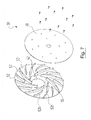
- the radial impeller 38 includes a flat wheel disc 48, which only in FIG. 1 can be seen and can be formed from a dimensionally stable material such as aluminum.
- the wheel disc 48 is connected to a blade part 50, which may be made of a plastic.
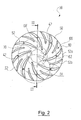
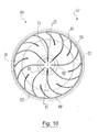
- the vane portion 50 includes the inlet port 42 and a plurality of vanes 52 that extend outward from the inlet port 42 in the center of the vane portion 50 with a radial component.
- vanes 52 are each provided with a reference numeral.
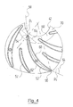
- the vanes 52 of the radial impeller 38 are curved and include a profile nose 54 and a tread end 56 and define a skeleton line in a manner known per se 58, which for clarity only a single vane 52 in FIG. 4 are provided with a reference numeral.
- the profile nose 54 designates the respective inflow end, which is adjacent to the inlet opening 42; the profile end 56 designates the respective outflow end of a guide vane 52, which lies away from the inlet opening 42.
- vanes 52 there are 16 vanes 52. In practice, with 12 to 18 vanes 52 an efficient delivery of the working fluid could be achieved.
- the vanes 52 have a flow flank 60 facing the inlet opening 42 and a curved flow flank 62 which is remote from the inlet opening 42 and curved.
- the guide vanes 52 are designed and arranged such that their angle of incidence ⁇ 1 relative to the profile nose 54 relative to the skeleton line 58 is 32 ° to 35 °.
- Angle of incidence ⁇ 1 is the angle between the skeleton line 58 at the profile nose 54 and a reference straight line 64 shown in dashed lines, which corresponds to a tangent to the inlet opening 42 which is parallel-displaced along a secant to the profile nose 54. wherein the secant extends through the skeleton line 58 on the profile nose 54 and through the central axis of the inlet opening 42. This is based FIG. 4 can be seen, with the secant is shown with short and long strokes, but bears no reference numerals.
- the guide vanes 52 are formed and arranged such that their outflow angle ⁇ 2 at the profile end 56 with respect to the skeleton line 58 37 ° up to 45 ° or 50 ° to 54 °.
- a reference line 64 is used as a reference, as is FIG. 4 is apparent.
- the outflow angle is also referred to as the blade exit angle.
- Angle of incidence ⁇ 1 and outflow angle ⁇ 2 are to be considered in a reference plane which runs parallel to the wheel disc 48 and in FIG. 4 is formed for example by the paper plane.
- the profile lugs 54 of the guide vanes 52 are rounded with a radius of 0.5 mm to 2 mm.
- the profile end 56 of the vanes 52 is rounded in each case with a radius of 0.5 mm to 1.0 mm.
- the fillets lie in planes parallel to the wheel disk 48.
- vanes 52 there are vanes 52a of a first type and vanes 52b of a second kind, of which only in FIG. 2 only one vane 52a, 52b are particularly marked.
- the guide vanes 52b of the second type have a smaller longitudinal extent than the guide vanes 52a of the first type and are each arranged between two guide vanes 52a of the first type, as shown in FIG FIG. 2 easy to recognize.
- the above geometric details on vanes 52 apply to the vanes 52a, 52b of both types.
- the radial impeller 38 is designed such that the ratio of the diameter of the inlet opening 42 to the effective diameter of the radial impeller 38 is between 1:10 and 1: 3.
- the effective diameter of the radial impeller 38 is predetermined by the clear contour of radially outermost profiled ends 56 of the guide vanes 52. For example, the wheel disc 48 and the blade portion 50 survive beyond this effective diameter.
- the inlet opening 42 has a diameter of 26 mm or 27 mm and the radial impeller has a working diameter of 100 mm.
- FIG. 3 can be seen extending the vanes 52 in the present embodiment in a Radring Scheme 66 of the radial impeller 38 which has a constant thickness. This thickness can be between 4.5 mm to 5 mm.
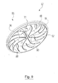
- the inlet opening 42 of the radial impeller 38 has a curved in the flow direction inner surface 68.
- the inlet opening 42 is bounded by an inlet collar 70 which extends in the axial direction of the radial impeller 38.
- the guide vanes 52 are with their end portion of the profile nose 54 of the inner circumferential surface 68, which is particularly in FIG. 3 easy to recognize.
- the inner circumferential surface 68 of the inlet opening 42 follows in the flow direction of a circular path, which is the section after FIG. 3 illustrated. In practice, good results could be achieved for radii of this circular path of 5 mm to 7 mm.
- FIG. 5 the flow connection between the guide 46 and the output-side radial impeller 38 of the blower unit 10 is shown again on a larger scale.
- the guide 46 comprises a connecting element in the form of a ring nozzle 72.
- annular gap 74 is formed, which has access to the inlet opening 42 in a Axis of the inlet opening 42 allows parallel direction, which coincides here with the axis 18 and does not bear its own reference numeral. This access is in FIG. 5 illustrated by arrows 76.
- annular nozzle 72 of the guide 46 immersed in the inlet opening 42 of the radial impeller 38, that the annular gap 74 between the inner circumferential surface 68 of the inlet opening 42 of the radial impeller 38 and an outer circumferential surface 78 of the annular nozzle 72 of the guide 46 is formed.
- the intake cover 20 comprises an annular skirt 81, which continues the intake manifold 16 and dips into the inlet opening 42 of the first, input-side radial impeller 38, forming an annular gap also designated 74.
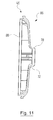
- FIG. 6 shows a blower unit 10 ', which is designed for clinical operation and of which details in the FIGS. 7 to 12 are shown. Components and components of the same function, which have already been explained above, are each provided with the same reference numerals.
- the outlet nozzle 24 is not visible there due to the cut.
- FIG. 6 On the housing 12 is in FIG. 6 can be seen above a connecting web 82 to which a not specifically shown control housing for the above-mentioned control unit is attached.
- the hospital blower unit 10 'corresponds to the working principle of the blower unit 10 after the FIGS. 1 to 5 , however, is modified in details in contrast.
- FIGS. 7 and 8th a modified radial impeller 38, in which the guide vanes 52 are formed and arranged with respect to the angle of incidence ⁇ 1 such that their angle of incidence ⁇ 1 at the profile nose 54 relative to the skeleton line 58 is 25 ° to 29 °.
- angle of incidence ⁇ 1 generally good flow results can be achieved if they are between 25 ° and 35 °. This also applies with respect to the radial impeller 38 after the FIGS. 1 to 5 ,
- vanes 52 are at the radial impeller 38 after the FIGS. 7 and 8th with respect to the outflow angle ⁇ 2 designed and arranged such that their outflow angle ⁇ 2 at the profile end 56 relative to the skeleton line 58 between 40 ° and 54 ° (see. FIG. 8 ), wherein with outflow angles ⁇ 2 between 40 ° and 45 °, and especially of 40 °, or between 50 ° to 54 ° good results were achieved.
- FIG. 7 also illustrates the above-described construction principle of the radial impellers 38. As can be seen there, the wheel disc 48 and the blade part 50 can be screwed together. The screws engage in the guide vanes 52.
- the guide vanes 52 have a thickness of 0.5 mm to 1.0 mm.
- the number of blades is here again 16, whereby in practice with 18 to 22 guide vanes 52 good results could be achieved.
- the Radring Scheme 66 is not substantially constant thickness, but has a thickness that converges in the radially outward direction. In the present embodiment of 7.5 mm to 2.5 mm. In a modification not specifically shown, the thickness converges from 13 mm to 7 mm or from 15 mm to 8 mm or 9 mm. But even a constant thickness can be provided, which is then eg 7 mm or between 8 mm and 9 mm.
- the effective diameter of the radial impellers 38 in the hospital blower unit 10 ' is between 160 mm and 190 mm, the inlet opening 42 has a diameter between 46 mm and 50 mm.
- an effective diameter of 160 mm and especially with an effective diameter of 182 mm particularly good results could be achieved.
- FIGS. 9 to 11 show the guide 46 in detail, which in this form also in the blower unit 10 after the FIGS. 1 to 5 can be present.
- the guide 46 is formed as a guide wheel 86, which remains stationary during operation of the hospital blower unit 10 'and is anchored to the housing.
- the deflecting wheel 86 comprises the annular nozzle 72 and deflecting means in the form of a plurality of deflecting vanes 88 on the opposite side of the annular nozzle 72, which extend radially outwardly from the central axis thereof.
- the turning vanes 88 are formed as flat webs and comprise from the inside to the outside a rectilinear portion 90, which merges into a curved portion 92 which describes approximately a quarter circle.
- the vanes 88 are of a first type and there are turning vanes 94 of a second type which have a smaller longitudinal extent than the turning vanes 88 of the first type and which are each disposed between two turning vanes 88 of the first type, as shown in FIG. 10 easy to recognize.
- the deflecting wheel 86 is generally designed such that the working fluid arrives at the inlet opening 42 of the second radial impeller 38 with little or no swirl, after it flows out of the through-passage 44 between the motor housing 30 and the housing 12. As a small swirl, for example, a twist of 5 ° understood.
- the curved portion 92 of a turning vane 88 is formed such that the working fluid from the passageway 44 impinges on the turning vane 88 at an angle of 15 ° to 25 °.
- FIG. 12 shows the flow transition from the guide wheel 86 to the second radial impeller 38 in a larger scale and again shows the annular gap 74 between the inner circumferential surface 68 of the inlet collar 70 of the radial impeller 38 and the outer lateral surface 78 of the annular nozzle 72 of the guide wheel 86, by the disturbing turbulence on entry of the working fluid in omit the second, output-side radial impeller 38.
- blower units 10 and 10 'can also be used as compressors, for example by sucking ambient air via the inlet pipe 16 and supplying the compressed air obtained at the outlet pipe 24 to a collecting tank.
- the radial impellers 38 lead by the fluidic measures, ie by the formation of the inlet opening 42 and the guide vanes 52 and by the converted dimensions and arrangements, to the required suction at relatively low energy consumption.
- the ratio of the diameter of the inlet opening 42 to the effective diameter of the respective radial impeller 38 which in the present case is between 1:10 and 1: 3, positively influences the obtainable efficiency.
- blower units 10 and 10 ' When the above-described blower units 10 and 10 'are operated in the dental practice, their suction side 14 is usually connected to the outlet side of a separator, through which a mixture of air, liquid and solids coming from the treatment place is separated, so that only the Air to the fan unit 10 or 10 'passes.
- a safety device is provided by which it is prevented that the blower 10 or 10 'can be operated when the upstream separator is inactive. In other words, the blower 10 or 10 'can only be operated if the upstream separator is activated.
- a rotational frequency signal can be taken from the motor of the separator; if there is no signal, the separator stands still and the blower 10 or 10 'is disabled. In this way it can also be monitored whether the speed of the separator is sufficiently high. If the speed is too low, the separation efficiency may be too low and there is the risk that liquid and / or solids will enter the blower 10, 10 '. Therefore, the operation of the blower 10 or 10 ', for example, already be blocked for safety, if the speed of the separator falls below a predetermined lower threshold.
- a suitable rotational frequency signal can be removed, for example, by means of a per se known Hall sensor, which cooperates with a magnet. This can be attached for example to a rotary shaft or a fan of the separator motor.
Landscapes
- Engineering & Computer Science (AREA)
- Health & Medical Sciences (AREA)
- General Engineering & Computer Science (AREA)
- Mechanical Engineering (AREA)
- General Health & Medical Sciences (AREA)
- Veterinary Medicine (AREA)
- Public Health (AREA)
- Life Sciences & Earth Sciences (AREA)
- Animal Behavior & Ethology (AREA)
- Dentistry (AREA)
- Epidemiology (AREA)
- Heart & Thoracic Surgery (AREA)
- Hematology (AREA)
- Biomedical Technology (AREA)
- Anesthesiology (AREA)
- Vascular Medicine (AREA)
- Structures Of Non-Positive Displacement Pumps (AREA)
- Dental Tools And Instruments Or Auxiliary Dental Instruments (AREA)
Applications Claiming Priority (1)
| Application Number | Priority Date | Filing Date | Title |
|---|---|---|---|
| DE102012023747.2A DE102012023747A1 (de) | 2012-12-04 | 2012-12-04 | Medizinisches oder dentales Gebläse |
Publications (2)
| Publication Number | Publication Date |
|---|---|
| EP2740942A2 true EP2740942A2 (fr) | 2014-06-11 |
| EP2740942A3 EP2740942A3 (fr) | 2014-12-24 |
Family
ID=49683396
Family Applications (1)
| Application Number | Title | Priority Date | Filing Date |
|---|---|---|---|
| EP13005525.4A Withdrawn EP2740942A3 (fr) | 2012-12-04 | 2013-11-27 | Ventilateur médical ou dentaire |
Country Status (4)
| Country | Link |
|---|---|
| EP (1) | EP2740942A3 (fr) |
| KR (1) | KR20140071917A (fr) |
| CN (1) | CN103850981A (fr) |
| DE (1) | DE102012023747A1 (fr) |
Cited By (1)
| Publication number | Priority date | Publication date | Assignee | Title |
|---|---|---|---|---|
| GB2531131A (en) * | 2014-10-10 | 2016-04-13 | Gilbert Gilkes & Gordon Ltd | Axial Flow Pumps |
Families Citing this family (5)
| Publication number | Priority date | Publication date | Assignee | Title |
|---|---|---|---|---|
| DE102015105188A1 (de) * | 2015-04-02 | 2016-10-06 | Ebm-Papst Mulfingen Gmbh & Co. Kg | Elektromotor mit drückender Kühlluftförderung sowie Verfahren zum Kühlen von Bauteilen des Elektromotors |
| DE102015105377A1 (de) * | 2015-04-09 | 2016-10-13 | Ebm-Papst Mulfingen Gmbh & Co. Kg | Elektromotor mit verbesserter Kühlung |
| JP7080743B2 (ja) * | 2018-06-21 | 2022-06-06 | シャープ株式会社 | 電動送風機および電動掃除機 |
| CN109869330A (zh) * | 2019-03-28 | 2019-06-11 | 大连海事大学 | 一种两级电动压气机 |
| EP3933207A1 (fr) * | 2020-06-29 | 2022-01-05 | Dürr Dental SE | Ventilateur médical avec système d'isolation acoustique, en particulier pour usage dentaire |
Citations (2)
| Publication number | Priority date | Publication date | Assignee | Title |
|---|---|---|---|---|
| DE2109409A1 (de) * | 1971-02-27 | 1972-09-07 | Luft U Kaeltetechnik Veb K | Anordnung zur Verminderung der Spaltverluste bei Lüftern mit schwingend gelagertem Laufrad |
| WO2002016777A1 (fr) * | 2000-08-21 | 2002-02-28 | Textron Automotive Company Inc. | Turbine centrifuge et carter correspondant |
Family Cites Families (7)
| Publication number | Priority date | Publication date | Assignee | Title |
|---|---|---|---|---|
| JPH09222097A (ja) * | 1996-02-19 | 1997-08-26 | Matsushita Refrig Co Ltd | 遠心送風機 |
| CN1338576A (zh) * | 2001-03-19 | 2002-03-06 | 中国兵器工业第五三研究所 | 塑料水泵叶轮 |
| US7273352B2 (en) * | 2004-01-09 | 2007-09-25 | United Technologies Corporation | Inlet partial blades for structural integrity and performance |
| DE102004028942B4 (de) * | 2004-06-15 | 2008-04-24 | Hellmut Ruck Gmbh | Gebläse für ein elektrisches Gerät sowie zugehöriges Baukastensystem |
| CN2760311Y (zh) * | 2004-12-02 | 2006-02-22 | 郭淑瑜 | 泡脚机泵的改进结构 |
| DE102006014682B4 (de) * | 2006-03-28 | 2017-02-02 | DüRR DENTAL AG | Saugmaschine |
| CN201152279Y (zh) * | 2007-08-23 | 2008-11-19 | 湖北双剑鼓风机制造有限公司 | 单级低速鼓风机的叶轮装置 |
-
2012
- 2012-12-04 DE DE102012023747.2A patent/DE102012023747A1/de not_active Ceased
-
2013
- 2013-11-27 EP EP13005525.4A patent/EP2740942A3/fr not_active Withdrawn
- 2013-12-02 KR KR1020130148277A patent/KR20140071917A/ko not_active Application Discontinuation
- 2013-12-04 CN CN201310647872.2A patent/CN103850981A/zh active Pending
Patent Citations (2)
| Publication number | Priority date | Publication date | Assignee | Title |
|---|---|---|---|---|
| DE2109409A1 (de) * | 1971-02-27 | 1972-09-07 | Luft U Kaeltetechnik Veb K | Anordnung zur Verminderung der Spaltverluste bei Lüftern mit schwingend gelagertem Laufrad |
| WO2002016777A1 (fr) * | 2000-08-21 | 2002-02-28 | Textron Automotive Company Inc. | Turbine centrifuge et carter correspondant |
Non-Patent Citations (1)
| Title |
|---|
| None |
Cited By (1)
| Publication number | Priority date | Publication date | Assignee | Title |
|---|---|---|---|---|
| GB2531131A (en) * | 2014-10-10 | 2016-04-13 | Gilbert Gilkes & Gordon Ltd | Axial Flow Pumps |
Also Published As
| Publication number | Publication date |
|---|---|
| DE102012023747A1 (de) | 2014-06-05 |
| EP2740942A3 (fr) | 2014-12-24 |
| KR20140071917A (ko) | 2014-06-12 |
| CN103850981A (zh) | 2014-06-11 |
Similar Documents
| Publication | Publication Date | Title |
|---|---|---|
| EP2740942A2 (fr) | Ventilateur médical ou dentaire | |
| DE102010046870B4 (de) | Seitenkanalgebläse, insbesondere Sekundärluftgebläse für eine Verbrennungskraftmaschine | |
| EP2875718B1 (fr) | Appareil de travail manuel doté d'un tube de soufflage | |
| DE102006014682B4 (de) | Saugmaschine | |
| WO2012130405A1 (fr) | Ventilateur diagonal | |
| AT510538B1 (de) | Zentrifugalpumpe | |
| DE102009006652B4 (de) | Seitenkanalgebläse, insbesondere Sekundärluftgebläse für eine Verbrennungskraftmaschine | |
| EP2171279B1 (fr) | Ensemble de pompes à amorçage automatique | |
| WO2006133577A1 (fr) | Pompe centrifuge | |
| DE19650748A1 (de) | Dentalturbine | |
| EP2808553B1 (fr) | Moteur électrique avec roue de ventilateur | |
| WO2009143920A1 (fr) | Ventilateur radial | |
| EP3303845B1 (fr) | Ensemble de pompes à amorçage automatique | |
| EP2940311B1 (fr) | Ventilateur radial présentant une géométrie de bord d'attaque améliorée | |
| DE10010077A1 (de) | Saugeinheit | |
| WO2019120550A1 (fr) | Ventilateur à canal latéral, notamment ventilateur à aire secondaire pour moteur à combustion interne | |
| EP2342464B1 (fr) | Ventilateur à canal latéral, en particulier turbine secondaire pour un moteur à combustion interne | |
| DE102005040305B4 (de) | Seitenkanalmaschine | |
| EP1538340A2 (fr) | Ventilateur diagonal compact | |
| EP1122444A2 (fr) | Ventilateur radial et buse pour ventilateur radial | |
| DE701458C (de) | Selbstansaugende Umlaufpumpe | |
| WO2010052044A1 (fr) | Soufflante à canal latéral, en particulier turbine secondaire pour un moteur à combustion interne | |
| EP3607210B1 (fr) | Soufflante radiale | |
| DE3622130A1 (de) | Kreiselpumpe zur foerderung gashaltiger medien | |
| EP3728860B1 (fr) | Compresseurs à canal latéral, en particulier compresseurs d'air secondaires pour un moteur à combustion interne |
Legal Events
| Date | Code | Title | Description |
|---|---|---|---|
| PUAI | Public reference made under article 153(3) epc to a published international application that has entered the european phase |
Free format text: ORIGINAL CODE: 0009012 |
|
| 17P | Request for examination filed |
Effective date: 20131127 |
|
| AK | Designated contracting states |
Kind code of ref document: A2 Designated state(s): AL AT BE BG CH CY CZ DE DK EE ES FI FR GB GR HR HU IE IS IT LI LT LU LV MC MK MT NL NO PL PT RO RS SE SI SK SM TR |
|
| AX | Request for extension of the european patent |
Extension state: BA ME |
|
| PUAL | Search report despatched |
Free format text: ORIGINAL CODE: 0009013 |
|
| AK | Designated contracting states |
Kind code of ref document: A3 Designated state(s): AL AT BE BG CH CY CZ DE DK EE ES FI FR GB GR HR HU IE IS IT LI LT LU LV MC MK MT NL NO PL PT RO RS SE SI SK SM TR |
|
| AX | Request for extension of the european patent |
Extension state: BA ME |
|
| RIC1 | Information provided on ipc code assigned before grant |
Ipc: F04D 17/12 20060101AFI20141119BHEP Ipc: A61C 17/06 20060101ALI20141119BHEP Ipc: F04D 17/16 20060101ALI20141119BHEP Ipc: F04D 29/16 20060101ALI20141119BHEP Ipc: F04D 29/28 20060101ALI20141119BHEP Ipc: F04D 29/30 20060101ALI20141119BHEP Ipc: F04D 29/44 20060101ALI20141119BHEP |
|
| R17P | Request for examination filed (corrected) |
Effective date: 20150623 |
|
| RBV | Designated contracting states (corrected) |
Designated state(s): AL AT BE BG CH CY CZ DE DK EE ES FI FR GB GR HR HU IE IS IT LI LT LU LV MC MK MT NL NO PL PT RO RS SE SI SK SM TR |
|
| STAA | Information on the status of an ep patent application or granted ep patent |
Free format text: STATUS: EXAMINATION IS IN PROGRESS |
|
| 17Q | First examination report despatched |
Effective date: 20180405 |
|
| RAP1 | Party data changed (applicant data changed or rights of an application transferred) |
Owner name: DUERR DENTAL SE |
|
| STAA | Information on the status of an ep patent application or granted ep patent |
Free format text: STATUS: EXAMINATION IS IN PROGRESS |
|
| STAA | Information on the status of an ep patent application or granted ep patent |
Free format text: STATUS: THE APPLICATION IS DEEMED TO BE WITHDRAWN |
|
| 18D | Application deemed to be withdrawn |
Effective date: 20210601 |