EP2740942A2 - Medical or dental blower - Google Patents
Medical or dental blower Download PDFInfo
- Publication number
- EP2740942A2 EP2740942A2 EP13005525.4A EP13005525A EP2740942A2 EP 2740942 A2 EP2740942 A2 EP 2740942A2 EP 13005525 A EP13005525 A EP 13005525A EP 2740942 A2 EP2740942 A2 EP 2740942A2
- Authority
- EP
- European Patent Office
- Prior art keywords
- radial impeller
- inlet opening
- blower according
- vanes
- guide
- Prior art date
- Legal status (The legal status is an assumption and is not a legal conclusion. Google has not performed a legal analysis and makes no representation as to the accuracy of the status listed.)
- Withdrawn
Links
Images


Classifications
-
- A—HUMAN NECESSITIES
- A61—MEDICAL OR VETERINARY SCIENCE; HYGIENE
- A61C—DENTISTRY; APPARATUS OR METHODS FOR ORAL OR DENTAL HYGIENE
- A61C17/00—Devices for cleaning, polishing, rinsing or drying teeth, teeth cavities or prostheses; Saliva removers; Dental appliances for receiving spittle
- A61C17/06—Saliva removers; Accessories therefor
-
- F—MECHANICAL ENGINEERING; LIGHTING; HEATING; WEAPONS; BLASTING
- F04—POSITIVE - DISPLACEMENT MACHINES FOR LIQUIDS; PUMPS FOR LIQUIDS OR ELASTIC FLUIDS
- F04D—NON-POSITIVE-DISPLACEMENT PUMPS
- F04D29/00—Details, component parts, or accessories
- F04D29/40—Casings; Connections of working fluid
- F04D29/42—Casings; Connections of working fluid for radial or helico-centrifugal pumps
- F04D29/44—Fluid-guiding means, e.g. diffusers
- F04D29/441—Fluid-guiding means, e.g. diffusers especially adapted for elastic fluid pumps
-
- A—HUMAN NECESSITIES
- A61—MEDICAL OR VETERINARY SCIENCE; HYGIENE
- A61C—DENTISTRY; APPARATUS OR METHODS FOR ORAL OR DENTAL HYGIENE
- A61C17/00—Devices for cleaning, polishing, rinsing or drying teeth, teeth cavities or prostheses; Saliva removers; Dental appliances for receiving spittle
- A61C17/02—Rinsing or air-blowing devices, e.g. using fluid jets or comprising liquid medication
- A61C17/022—Air-blowing devices, e.g. with means for heating the air
-
- A—HUMAN NECESSITIES
- A61—MEDICAL OR VETERINARY SCIENCE; HYGIENE
- A61M—DEVICES FOR INTRODUCING MEDIA INTO, OR ONTO, THE BODY; DEVICES FOR TRANSDUCING BODY MEDIA OR FOR TAKING MEDIA FROM THE BODY; DEVICES FOR PRODUCING OR ENDING SLEEP OR STUPOR
- A61M1/00—Suction or pumping devices for medical purposes; Devices for carrying-off, for treatment of, or for carrying-over, body-liquids; Drainage systems
-
- F—MECHANICAL ENGINEERING; LIGHTING; HEATING; WEAPONS; BLASTING
- F04—POSITIVE - DISPLACEMENT MACHINES FOR LIQUIDS; PUMPS FOR LIQUIDS OR ELASTIC FLUIDS
- F04D—NON-POSITIVE-DISPLACEMENT PUMPS
- F04D17/00—Radial-flow pumps, e.g. centrifugal pumps; Helico-centrifugal pumps
- F04D17/08—Centrifugal pumps
- F04D17/16—Centrifugal pumps for displacing without appreciable compression
- F04D17/164—Multi-stage fans, e.g. for vacuum cleaners
-
- F—MECHANICAL ENGINEERING; LIGHTING; HEATING; WEAPONS; BLASTING
- F04—POSITIVE - DISPLACEMENT MACHINES FOR LIQUIDS; PUMPS FOR LIQUIDS OR ELASTIC FLUIDS
- F04D—NON-POSITIVE-DISPLACEMENT PUMPS
- F04D29/00—Details, component parts, or accessories
- F04D29/08—Sealings
- F04D29/16—Sealings between pressure and suction sides
- F04D29/161—Sealings between pressure and suction sides especially adapted for elastic fluid pumps
- F04D29/162—Sealings between pressure and suction sides especially adapted for elastic fluid pumps of a centrifugal flow wheel
-
- F—MECHANICAL ENGINEERING; LIGHTING; HEATING; WEAPONS; BLASTING
- F04—POSITIVE - DISPLACEMENT MACHINES FOR LIQUIDS; PUMPS FOR LIQUIDS OR ELASTIC FLUIDS
- F04D—NON-POSITIVE-DISPLACEMENT PUMPS
- F04D29/00—Details, component parts, or accessories
- F04D29/26—Rotors specially for elastic fluids
- F04D29/28—Rotors specially for elastic fluids for centrifugal or helico-centrifugal pumps for radial-flow or helico-centrifugal pumps
- F04D29/281—Rotors specially for elastic fluids for centrifugal or helico-centrifugal pumps for radial-flow or helico-centrifugal pumps for fans or blowers
-
- F—MECHANICAL ENGINEERING; LIGHTING; HEATING; WEAPONS; BLASTING
- F04—POSITIVE - DISPLACEMENT MACHINES FOR LIQUIDS; PUMPS FOR LIQUIDS OR ELASTIC FLUIDS
- F04D—NON-POSITIVE-DISPLACEMENT PUMPS
- F04D29/00—Details, component parts, or accessories
- F04D29/26—Rotors specially for elastic fluids
- F04D29/28—Rotors specially for elastic fluids for centrifugal or helico-centrifugal pumps for radial-flow or helico-centrifugal pumps
- F04D29/30—Vanes
-
- F—MECHANICAL ENGINEERING; LIGHTING; HEATING; WEAPONS; BLASTING
- F04—POSITIVE - DISPLACEMENT MACHINES FOR LIQUIDS; PUMPS FOR LIQUIDS OR ELASTIC FLUIDS
- F04D—NON-POSITIVE-DISPLACEMENT PUMPS
- F04D29/00—Details, component parts, or accessories
- F04D29/40—Casings; Connections of working fluid
- F04D29/42—Casings; Connections of working fluid for radial or helico-centrifugal pumps
- F04D29/4206—Casings; Connections of working fluid for radial or helico-centrifugal pumps especially adapted for elastic fluid pumps
- F04D29/4213—Casings; Connections of working fluid for radial or helico-centrifugal pumps especially adapted for elastic fluid pumps suction ports
-
- F—MECHANICAL ENGINEERING; LIGHTING; HEATING; WEAPONS; BLASTING
- F05—INDEXING SCHEMES RELATING TO ENGINES OR PUMPS IN VARIOUS SUBCLASSES OF CLASSES F01-F04
- F05D—INDEXING SCHEME FOR ASPECTS RELATING TO NON-POSITIVE-DISPLACEMENT MACHINES OR ENGINES, GAS-TURBINES OR JET-PROPULSION PLANTS
- F05D2250/00—Geometry
- F05D2250/50—Inlet or outlet
- F05D2250/51—Inlet
Definitions
- blowers are known from the market and can be used depending on the external wiring as suction or compressors.
- suction or compressors In particular, side channel blowers have become established.
- the object of the invention is to provide a fan of the type mentioned above, which in this respect improved in the prior art.
- the invention is based on the finding that by means of a radial fan relatively high negative pressures of up to 200 mbar can be achieved.
- a radial fan in conjunction with an electronically commutated electric motor so is a particularly effective and energy-efficient fan available.
- the efficiency of the fan is particularly influenced by the flow of the working fluid through the fan.
- the efficiency of the fan is the higher, the more undisturbed and barrier-free the flow path of the working fluid between the fluid inlet and the fluid outlet.
- the possibilities must be taken into account, which allows the existing space in the interior of the fan space with the components housed therein.
- a guide device is present, via which working fluid is conducted to the inlet opening of the radial impeller.
- the working fluid can be directed on a targeted flow path to the radial impeller.
- connection element between the connection element and the inlet opening of the radial impeller, an annular gap is formed, which has access to the inlet opening in a direction parallel to the axis of the inlet opening direction permits.
- an impeller Since an impeller must be rotatably mounted, there still remains a passage gap, which then runs at an angle. In general, therefore, false air is still sucked, which then due to the angled passage gap strongly swirling enters the impeller and generates turbulence in the flow of the working fluid, which in turn reduce the efficiency of the fan.
- the false air flows parallel to the working fluid in the radial impeller, avoid this turbulence; the false air acts as if in the working air flow, without significantly affecting its flow.
- the connecting element of the guide device preferably dips into the inlet opening of the radial impeller in such a way that the annular gap is formed between an inner lateral surface of the inlet opening of the radial impeller and an outer lateral surface of the connecting element of the guide device.
- the connection element of the guide device thus forms a male part and the inlet opening of the radial impeller forms a female part of a flow connection between these components.
- the working fluid can be promoted particularly effective by the radial impeller, when the guide is designed such that the working fluid arrives largely without or only with a small swirl at the inlet opening of the radial impeller.
- the working fluid is effective in the radial impeller and without flow disturbances from an axial flow direction in deflected a radial flow direction when the inlet opening of the radial impeller has a curved in the flow direction inner circumferential surface.
- the vanes of the radial impeller comprise a profile nose and a tread end and define a skeleton line.
- the guide vanes are designed and arranged such that their angle of incidence at the profile nose with respect to the skeleton line is 25 ° to 35 °, preferably 32 ° to 35 ° or 25 ° to 29 °.
- the angle of attack is 25 °.
- the blower is particularly efficient and undesirable turbulence on the vanes is reduced.
- the guide vanes are designed and arranged in such a way that their outflow angle at the profile end relative to the skeleton line is 37 ° to 45 ° or 50 ° to 54 °.
- the outflow angle is 40 °, in particular, if the above-mentioned angle of attack is 25 °. With these outflow angles particularly lossless stalls are achieved.
- the profile end is rounded with a radius of 0.5 mm to 1.0 mm.
- the radial impeller vanes of a first type and vanes of a second type wherein the vanes of the second type have a smaller longitudinal extent than the vanes of the first type and each between two vanes of the first kind are arranged.
- Efficient radial impellers and blowers equipped therewith are formed when the ratio of the diameter of the inlet opening to the effective diameter of the radial impeller is between 1:10 and 1: 3, wherein the effective diameter of the radial impeller is determined by the light contour of radially outermost profiled ends of the vanes ,
- a particularly favorable impeller geometry is when the inlet opening has a diameter of 26 mm or 27 mm and the radial impeller has a working diameter of 100 mm or if the inlet opening has a diameter of 46 mm to 50 mm and the radial impeller has a working diameter of 160 mm to 190 mm Has.
- a radial impeller with a larger effective diameter particularly good results could be achieved with a radial impeller whose inlet opening has a diameter of 46 mm.
- the effective diameter with a value of 160 mm, a good and, with an effective diameter of 182 mm, a particularly good result could be achieved.
- the guide vanes preferably extend in a Radring Scheme the radial impeller, which has a constant thickness, preferably from 4.5 mm to 5 mm or 7 mm or from 8 mm to 9 mm, or a thickness which is in the radial direction converges on the outside, preferably from 7.5 mm to 2.5 mm or from 13 mm to 7 mm or from 15 mm to 8 mm or 9 mm.
- FIG. 1 10 is a total of a dental blower unit, which is used as a suction unit for one or more dental treatment stations.
- the blower unit 10 comprises a multipart, generally largely cylindrical housing 12. At a suction side 14 of the housing 12 is located as a fluid inlet inlet nozzle 16 which is coaxial to the longitudinal axis 18 of the housing 12 and part of a suction cover 20. On an opposite discharge side 22 is provided as a fluid outlet, an outlet port 24 which extends in a manner known per se in the radial direction to the outside and in FIG. 1 can only be seen as a circular passage opening. The dispensing nozzle 24 in turn is part of a dispensing cover 26 of the housing 12. The inlet nozzle 16 and the outlet nozzle 24 are fluidically connected to each other.
- an electric motor 28 is housed, which in turn comprises a cylindrical motor housing 30 which is arranged coaxially with the housing 12.
- the electric motor 28 is designed as an internal rotor motor and operates at speeds between 20,000 rpm and 30,000 rpm. In practice, the electric motor 28 is an electronically commutated DC motor.
- the electric motor 28 may also be designed as an external rotor, whereby a larger torque can be obtained. However, a faster starting of the electric motor 28 from standstill is supported by an internal rotor motor.
- a stator 32 is fixed.
- a trained as a rotary shaft rotor 34 extends through the motor housing 30 through and protrudes through two bearing openings 36 at the end faces of the motor housing 30 to the outside in the suction cover 20 and the discharge cover 26 into it.
- the respective end of the rotor 34 rotatably carries a first, input-side radial impeller 38 and a second, output-side radial impeller 38, which are identical and will be explained in more detail below.
- the radial impellers 38 constitute fluid conveying means of a working unit 40 formed as a radial unit.
- the radial impellers 38 have a central inlet opening 42 and convey a working fluid from the inlet stub 16 to the outlet stub 24.
- the working fluid is usually air.
- the working fluid is sucked through the inlet port 16 to the inlet opening 42 of the first radial impeller 38 and compressed by the latter.
- the first radial impeller 38 forms a first compressor stage.
- the working fluid flows through the suction cover 20 of the housing 12 and passes from there to a through-passage 44, which is formed between the housing 12 and the motor housing 30.
- the second radial impeller 38 likewise driven by the electric motor 14 compresses the working fluid coming from the passage 44 and forms a second compressor stage. From the outlet port 42, the working fluid, optionally discharged via a leading out of the installation room of the blower unit discharge line to the environment.
- a guide 46 of the working unit 40 is arranged, which selectively directs working fluid coming from the passage 44 to the inlet opening 42 of the second radial impeller 38. This serves as a second compressor stage; the working fluid then flows into the discharge lid 26 of the housing 12 and is discharged from there through the outlet port 24 from the housing 12 out.
- the working fluid flowing through the passageway 44 cools the electric motor 28 on the outside of the motor housing 30.
- a portion of the working fluid flowing through the housing 12 can be used to also cool the electric motor 28 by passing this working fluid through the motor housing 30, where it can flow past the stator 32 and the rotor 34 and absorb heat there.
- the working fluid is expediently passed through a filter to the working fluid, for example, entrained solid particles to free.
- a protective valve which prevents backflow of working fluid into the housing interior, which may be contaminated after flowing through the motor housing 30 with abrasion or the like. Also, the intrusion of condensate from the output side of the blower unit 10 into the motor housing 30 can be prevented.
- the blower unit 10 comprises, in a manner known per se, a control unit which is not specifically shown and which controls or controls the speed of the electric motor 28 and other operating parameters.
- a control unit can also be stored various selectable operating parameter sets that define different operating modes of the blower unit 10.
- the radial impellers 38 are now based on the FIGS. 1 to 4 explained.
- the radial impeller 38 includes a flat wheel disc 48, which only in FIG. 1 can be seen and can be formed from a dimensionally stable material such as aluminum.
- the wheel disc 48 is connected to a blade part 50, which may be made of a plastic.
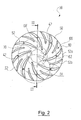
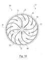
- the vane portion 50 includes the inlet port 42 and a plurality of vanes 52 that extend outward from the inlet port 42 in the center of the vane portion 50 with a radial component.
- vanes 52 are each provided with a reference numeral.
- the vanes 52 of the radial impeller 38 are curved and include a profile nose 54 and a tread end 56 and define a skeleton line in a manner known per se 58, which for clarity only a single vane 52 in FIG. 4 are provided with a reference numeral.
- the profile nose 54 designates the respective inflow end, which is adjacent to the inlet opening 42; the profile end 56 designates the respective outflow end of a guide vane 52, which lies away from the inlet opening 42.
- vanes 52 there are 16 vanes 52. In practice, with 12 to 18 vanes 52 an efficient delivery of the working fluid could be achieved.
- the vanes 52 have a flow flank 60 facing the inlet opening 42 and a curved flow flank 62 which is remote from the inlet opening 42 and curved.
- the guide vanes 52 are designed and arranged such that their angle of incidence ⁇ 1 relative to the profile nose 54 relative to the skeleton line 58 is 32 ° to 35 °.
- Angle of incidence ⁇ 1 is the angle between the skeleton line 58 at the profile nose 54 and a reference straight line 64 shown in dashed lines, which corresponds to a tangent to the inlet opening 42 which is parallel-displaced along a secant to the profile nose 54. wherein the secant extends through the skeleton line 58 on the profile nose 54 and through the central axis of the inlet opening 42. This is based FIG. 4 can be seen, with the secant is shown with short and long strokes, but bears no reference numerals.
- the guide vanes 52 are formed and arranged such that their outflow angle ⁇ 2 at the profile end 56 with respect to the skeleton line 58 37 ° up to 45 ° or 50 ° to 54 °.
- a reference line 64 is used as a reference, as is FIG. 4 is apparent.
- the outflow angle is also referred to as the blade exit angle.
- Angle of incidence ⁇ 1 and outflow angle ⁇ 2 are to be considered in a reference plane which runs parallel to the wheel disc 48 and in FIG. 4 is formed for example by the paper plane.
- the profile lugs 54 of the guide vanes 52 are rounded with a radius of 0.5 mm to 2 mm.
- the profile end 56 of the vanes 52 is rounded in each case with a radius of 0.5 mm to 1.0 mm.
- the fillets lie in planes parallel to the wheel disk 48.
- vanes 52 there are vanes 52a of a first type and vanes 52b of a second kind, of which only in FIG. 2 only one vane 52a, 52b are particularly marked.
- the guide vanes 52b of the second type have a smaller longitudinal extent than the guide vanes 52a of the first type and are each arranged between two guide vanes 52a of the first type, as shown in FIG FIG. 2 easy to recognize.
- the above geometric details on vanes 52 apply to the vanes 52a, 52b of both types.
- the radial impeller 38 is designed such that the ratio of the diameter of the inlet opening 42 to the effective diameter of the radial impeller 38 is between 1:10 and 1: 3.
- the effective diameter of the radial impeller 38 is predetermined by the clear contour of radially outermost profiled ends 56 of the guide vanes 52. For example, the wheel disc 48 and the blade portion 50 survive beyond this effective diameter.
- the inlet opening 42 has a diameter of 26 mm or 27 mm and the radial impeller has a working diameter of 100 mm.
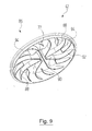
- FIG. 3 can be seen extending the vanes 52 in the present embodiment in a Radring Scheme 66 of the radial impeller 38 which has a constant thickness. This thickness can be between 4.5 mm to 5 mm.
- the inlet opening 42 of the radial impeller 38 has a curved in the flow direction inner surface 68.
- the inlet opening 42 is bounded by an inlet collar 70 which extends in the axial direction of the radial impeller 38.
- the guide vanes 52 are with their end portion of the profile nose 54 of the inner circumferential surface 68, which is particularly in FIG. 3 easy to recognize.
- the inner circumferential surface 68 of the inlet opening 42 follows in the flow direction of a circular path, which is the section after FIG. 3 illustrated. In practice, good results could be achieved for radii of this circular path of 5 mm to 7 mm.
- FIG. 5 the flow connection between the guide 46 and the output-side radial impeller 38 of the blower unit 10 is shown again on a larger scale.
- the guide 46 comprises a connecting element in the form of a ring nozzle 72.
- annular gap 74 is formed, which has access to the inlet opening 42 in a Axis of the inlet opening 42 allows parallel direction, which coincides here with the axis 18 and does not bear its own reference numeral. This access is in FIG. 5 illustrated by arrows 76.
- annular nozzle 72 of the guide 46 immersed in the inlet opening 42 of the radial impeller 38, that the annular gap 74 between the inner circumferential surface 68 of the inlet opening 42 of the radial impeller 38 and an outer circumferential surface 78 of the annular nozzle 72 of the guide 46 is formed.
- the intake cover 20 comprises an annular skirt 81, which continues the intake manifold 16 and dips into the inlet opening 42 of the first, input-side radial impeller 38, forming an annular gap also designated 74.
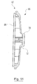
- FIG. 6 shows a blower unit 10 ', which is designed for clinical operation and of which details in the FIGS. 7 to 12 are shown. Components and components of the same function, which have already been explained above, are each provided with the same reference numerals.
- the outlet nozzle 24 is not visible there due to the cut.
- FIG. 6 On the housing 12 is in FIG. 6 can be seen above a connecting web 82 to which a not specifically shown control housing for the above-mentioned control unit is attached.
- the hospital blower unit 10 'corresponds to the working principle of the blower unit 10 after the FIGS. 1 to 5 , however, is modified in details in contrast.
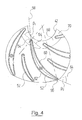
- FIGS. 7 and 8th a modified radial impeller 38, in which the guide vanes 52 are formed and arranged with respect to the angle of incidence ⁇ 1 such that their angle of incidence ⁇ 1 at the profile nose 54 relative to the skeleton line 58 is 25 ° to 29 °.
- angle of incidence ⁇ 1 generally good flow results can be achieved if they are between 25 ° and 35 °. This also applies with respect to the radial impeller 38 after the FIGS. 1 to 5 ,
- vanes 52 are at the radial impeller 38 after the FIGS. 7 and 8th with respect to the outflow angle ⁇ 2 designed and arranged such that their outflow angle ⁇ 2 at the profile end 56 relative to the skeleton line 58 between 40 ° and 54 ° (see. FIG. 8 ), wherein with outflow angles ⁇ 2 between 40 ° and 45 °, and especially of 40 °, or between 50 ° to 54 ° good results were achieved.
- FIG. 7 also illustrates the above-described construction principle of the radial impellers 38. As can be seen there, the wheel disc 48 and the blade part 50 can be screwed together. The screws engage in the guide vanes 52.
- the guide vanes 52 have a thickness of 0.5 mm to 1.0 mm.
- the number of blades is here again 16, whereby in practice with 18 to 22 guide vanes 52 good results could be achieved.
- the Radring Scheme 66 is not substantially constant thickness, but has a thickness that converges in the radially outward direction. In the present embodiment of 7.5 mm to 2.5 mm. In a modification not specifically shown, the thickness converges from 13 mm to 7 mm or from 15 mm to 8 mm or 9 mm. But even a constant thickness can be provided, which is then eg 7 mm or between 8 mm and 9 mm.
- the effective diameter of the radial impellers 38 in the hospital blower unit 10 ' is between 160 mm and 190 mm, the inlet opening 42 has a diameter between 46 mm and 50 mm.
- an effective diameter of 160 mm and especially with an effective diameter of 182 mm particularly good results could be achieved.
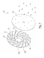
- FIGS. 9 to 11 show the guide 46 in detail, which in this form also in the blower unit 10 after the FIGS. 1 to 5 can be present.
- the guide 46 is formed as a guide wheel 86, which remains stationary during operation of the hospital blower unit 10 'and is anchored to the housing.
- the deflecting wheel 86 comprises the annular nozzle 72 and deflecting means in the form of a plurality of deflecting vanes 88 on the opposite side of the annular nozzle 72, which extend radially outwardly from the central axis thereof.
- the turning vanes 88 are formed as flat webs and comprise from the inside to the outside a rectilinear portion 90, which merges into a curved portion 92 which describes approximately a quarter circle.
- the vanes 88 are of a first type and there are turning vanes 94 of a second type which have a smaller longitudinal extent than the turning vanes 88 of the first type and which are each disposed between two turning vanes 88 of the first type, as shown in FIG. 10 easy to recognize.
- the deflecting wheel 86 is generally designed such that the working fluid arrives at the inlet opening 42 of the second radial impeller 38 with little or no swirl, after it flows out of the through-passage 44 between the motor housing 30 and the housing 12. As a small swirl, for example, a twist of 5 ° understood.
- the curved portion 92 of a turning vane 88 is formed such that the working fluid from the passageway 44 impinges on the turning vane 88 at an angle of 15 ° to 25 °.
- FIG. 12 shows the flow transition from the guide wheel 86 to the second radial impeller 38 in a larger scale and again shows the annular gap 74 between the inner circumferential surface 68 of the inlet collar 70 of the radial impeller 38 and the outer lateral surface 78 of the annular nozzle 72 of the guide wheel 86, by the disturbing turbulence on entry of the working fluid in omit the second, output-side radial impeller 38.
- blower units 10 and 10 'can also be used as compressors, for example by sucking ambient air via the inlet pipe 16 and supplying the compressed air obtained at the outlet pipe 24 to a collecting tank.
- the radial impellers 38 lead by the fluidic measures, ie by the formation of the inlet opening 42 and the guide vanes 52 and by the converted dimensions and arrangements, to the required suction at relatively low energy consumption.
- the ratio of the diameter of the inlet opening 42 to the effective diameter of the respective radial impeller 38 which in the present case is between 1:10 and 1: 3, positively influences the obtainable efficiency.
- blower units 10 and 10 ' When the above-described blower units 10 and 10 'are operated in the dental practice, their suction side 14 is usually connected to the outlet side of a separator, through which a mixture of air, liquid and solids coming from the treatment place is separated, so that only the Air to the fan unit 10 or 10 'passes.
- a safety device is provided by which it is prevented that the blower 10 or 10 'can be operated when the upstream separator is inactive. In other words, the blower 10 or 10 'can only be operated if the upstream separator is activated.
- a rotational frequency signal can be taken from the motor of the separator; if there is no signal, the separator stands still and the blower 10 or 10 'is disabled. In this way it can also be monitored whether the speed of the separator is sufficiently high. If the speed is too low, the separation efficiency may be too low and there is the risk that liquid and / or solids will enter the blower 10, 10 '. Therefore, the operation of the blower 10 or 10 ', for example, already be blocked for safety, if the speed of the separator falls below a predetermined lower threshold.
- a suitable rotational frequency signal can be removed, for example, by means of a per se known Hall sensor, which cooperates with a magnet. This can be attached for example to a rotary shaft or a fan of the separator motor.
Abstract
Description
Die Erfindung betrifft ein medizinisches oder dentales Gebläse zum Absaugen oder Verdichten eines gasförmigen Arbeitsfluids, insbesondere von Luft, mit
- a) einem Gehäuse, welches einen Fluideinlass und einen Fluidauslass umfasst, die strömungstechnisch miteinander verbunden sind;
- b) einer Arbeitseinheit, die Fluidfördermittel umfasst, welche mittels eines Elektromotors, insbesondere mittels eines elektronisch kommutierten Elektromotors, antreibbar sind und durch welche Arbeitsfluid vom Fluideinlass zum Fluidauslass förderbar ist.
- a) a housing comprising a fluid inlet and a fluid outlet fluidly connected to each other;
- b) a working unit, which comprises fluid conveying means, which are drivable by means of an electric motor, in particular by means of an electronically commutated electric motor, and by which working fluid from the fluid inlet to the fluid outlet can be conveyed.
Derartige Gebläse sind vom Markt her bekannt und können je nach externer Beschaltung als Saugmaschinen oder Kompressoren eingesetzt werden. Insbesondere haben sich dabei Seitenkanalgebläse etabliert.Such blowers are known from the market and can be used depending on the external wiring as suction or compressors. In particular, side channel blowers have become established.
Insbesondere im dentalen Bereich ist bei solchen Gebläsen ein hoher Wirkungsgrad und eine hohe Effizienz wünschenswert, bei denen eine hohe Gebläseleistung bei gleichzeitig günstigerem Energieverbrauch sicherstellt ist. Im dentalen Praxisbetrieb, bei dem das Gebläse zum Absaugen von Flüssigkeiten und Feststoffen dient, die am Behandlungsplatz anfallen, ist das Gebläse häufig nahe der von Mitarbeitern und Patienten genutzten Räume untergebracht. Daher ist dort insbesondere auch eine moderate Geräuschentwicklung wünschenswert.Particularly in the dental field, high efficiency and high efficiency are desirable in such blowers, in which a high blower power is ensured at the same time more favorable energy consumption. In dental practice, where the fan is used to aspirate liquids and solids that are generated at the treatment site, the fan is often located near the rooms used by staff and patients. Therefore, especially a moderate noise development is desirable there.
Aufgabe der Erfindung ist, ein Gebläse der eingangs genannten Art bereitzustellen, welches in dieser Hinsicht gegenüber dem Stand der Technik verbessert ist.The object of the invention is to provide a fan of the type mentioned above, which in this respect improved in the prior art.
Diese Aufgabe wird bei einem Gebläse der eingangs genannten Art dadurch gelöst, dass
- c) die Arbeitseinheit eine Radialeinheit ist und die Fluidfördermittel wenigstens ein Radiallaufrad mit mehreren Leitschaufeln und einer zentralen Einlassöffnung umfassen.
- c) the working unit is a radial unit and the fluid conveying means comprise at least one radial impeller with a plurality of guide vanes and a central inlet opening.
Die Erfindung beruht auf der Erkenntnis, dass mittels eines Radialgebläses besonders effektiv verhältnismäßig hohe Unterdrücke bis zu 200 mbar erreicht werden können. Insbesondere in Verbindung mit einem elektronisch kommutierten Elektromotor steht so ein besonders effektives und energiesparendes Gebläse zur Verfügung.The invention is based on the finding that by means of a radial fan relatively high negative pressures of up to 200 mbar can be achieved. In particular, in conjunction with an electronically commutated electric motor so is a particularly effective and energy-efficient fan available.
Der Wirkungsgrad des Gebläses wird besonders auch durch die Strömungsführung des Arbeitsfluids durch das Gebläse beeinflusst. Der Wirkungsgrad des Gebläses ist umso höher, je ungestörter und barrierefreier der Strömungsweg des Arbeitsfluids zwischen dem Fluideinlass und dem Fluidauslass ist. Dabei muss jedoch den Möglichkeiten Rechnung getragen werden, die der im Innenraum des Gebläses vorhandene Bauraum mit den darin untergebrachten Komponenten zulässt.The efficiency of the fan is particularly influenced by the flow of the working fluid through the fan. The efficiency of the fan is the higher, the more undisturbed and barrier-free the flow path of the working fluid between the fluid inlet and the fluid outlet. However, the possibilities must be taken into account, which allows the existing space in the interior of the fan space with the components housed therein.
Es hat sich beispielsweise als günstig erwiesen, wenn eine Leiteinrichtung vorhanden ist, über welche Arbeitsfluid zur Einlassöffnung des Radiallaufrades geleitet wird. So kann das Arbeitsfluid auf einem gezielten Strömungsweg zum Radiallaufrad geleitet werden.For example, it has proved to be advantageous if a guide device is present, via which working fluid is conducted to the inlet opening of the radial impeller. Thus, the working fluid can be directed on a targeted flow path to the radial impeller.
Besonders von Vorteil ist es, wenn zwischen dem Anschlusselement und der Einlassöffnung des Radiallaufrades ein Ringspalt ausgebildet ist, der einen Zugang zur Einlassöffnung in einer zur Achse der Einlassöffnung parallele Richtung zulässt. Üblicherweise werden Versuche unternommen, eine solche Verbindungsstelle zu einem Laufrad durch gewinkelte, ineinander greifende Dichtstrukturen abzudichten und das Ansaugen von Falschluft aus Bereichen neben der Verbindungsstelle zu verhindern. Da ein Laufrad verdrehbar gelagert sein muss, bleibt dennoch ein Durchgangsspalt bestehen, der dann gewinkelt verläuft. In der Regel wird daher dennoch Falschluft angesaugt, die dann auf Grund des gewinkelten Durchgangsspaltes stark verwirbelt in das Laufrad gelangt und in der Strömung des Arbeitsfluids Turbulenzen erzeugt, die wiederum die Effizienz des Gebläses herabsetzen. Wenn die Falschluft jedoch parallel zum Arbeitsfluid in das Radiallaufrad einströmt, unterbleiben diese Turbulenzen; die Falschluft geht gleichsam in dem Arbeitsluftstrom auf, ohne dessen Strömung merklich zu beeinflussen.It is particularly advantageous if, between the connection element and the inlet opening of the radial impeller, an annular gap is formed, which has access to the inlet opening in a direction parallel to the axis of the inlet opening direction permits. Usually attempts are made to seal such a connection point to an impeller by angled, interlocking sealing structures and to prevent the suction of false air from areas adjacent to the connection point. Since an impeller must be rotatably mounted, there still remains a passage gap, which then runs at an angle. In general, therefore, false air is still sucked, which then due to the angled passage gap strongly swirling enters the impeller and generates turbulence in the flow of the working fluid, which in turn reduce the efficiency of the fan. However, if the false air flows parallel to the working fluid in the radial impeller, avoid this turbulence; the false air acts as if in the working air flow, without significantly affecting its flow.
Vorzugsweise taucht das Anschlusselement der Leiteinrichtung derart in die Einlassöffnung des Radiallaufrades ein, dass der Ringspalt zwischen einer Innenmantelfläche der Einlassöffnung des Radiallaufrades und einer Außenmantelfläche des Anschlusselements der Leiteinrichtung ausgebildet ist. Im weiteren Sinne bildet somit das Anschlusselement der Leiteinrichtung einen männlichen Teil und die Einlassöffnung des Radiallaufrades einen weiblichen Teil einer Strömungsverbindung zwischen diesen Komponenten.The connecting element of the guide device preferably dips into the inlet opening of the radial impeller in such a way that the annular gap is formed between an inner lateral surface of the inlet opening of the radial impeller and an outer lateral surface of the connecting element of the guide device. In a broader sense, the connection element of the guide device thus forms a male part and the inlet opening of the radial impeller forms a female part of a flow connection between these components.
Das Arbeitsfluid kann besonders effektiv von dem Radiallaufrad gefördert werden, wenn die Leiteinrichtung derart ausgebildet ist, dass das Arbeitsfluid weitgehend ohne oder nur mit einem geringen Drall an der Einlassöffnung des Radiallaufrades ankommt.The working fluid can be promoted particularly effective by the radial impeller, when the guide is designed such that the working fluid arrives largely without or only with a small swirl at the inlet opening of the radial impeller.
Das Arbeitsfluid wird im Radiallaufrad effektiv und ohne Strömungsstörungen aus einer axialen Strömungsrichtung in eine radiale Strömungsrichtung umgelenkt, wenn die Einlassöffnung des Radiallaufrades eine in Strömungsrichtung gekrümmte Innenmantelfläche aufweist.The working fluid is effective in the radial impeller and without flow disturbances from an axial flow direction in deflected a radial flow direction when the inlet opening of the radial impeller has a curved in the flow direction inner circumferential surface.
Es ist dafür günstig, wenn die Einlassöffnung des Radiallaufrades durch einen Einlasskragen begrenzt ist.It is favorable if the inlet opening of the radial impeller is limited by an inlet collar.
Es hat sich als besonders strömungsgünstig erwiesen, wenn eine Innenmantelfläche der Einlassöffnung in Strömungsrichtung einer Kreisbahn, vorzugsweise mit einem Radius von 5 mm bis 7 mm, folgt.It has proven to be particularly streamlined when an inner circumferential surface of the inlet opening in the flow direction of a circular path, preferably with a radius of 5 mm to 7 mm, follows.
Die Leitschaufeln des Radiallaufrades umfassen eine Profilnase und ein Profilende und definieren eine Skelettlinie. Strömungstechnisch ist es besonders effektiv, wenn die Leitschaufeln derart ausgebildet und angeordnet sind, dass deren Anströmwinkel an der Profilnase bezogen auf die Skelettlinie 25° bis 35°, vorzugsweise 32° bis 35° oder 25° bis 29°, beträgt. Vorzugsweise beträgt der Anströmwinkel 25°. Mit solchen Leitschaufeln arbeitet das Gebläse besonders effizient und unerwünschte Verwirbelungen an den Leitschaufeln sind verringert.The vanes of the radial impeller comprise a profile nose and a tread end and define a skeleton line. In terms of flow technology, it is particularly effective if the guide vanes are designed and arranged such that their angle of incidence at the profile nose with respect to the skeleton line is 25 ° to 35 °, preferably 32 ° to 35 ° or 25 ° to 29 °. Preferably, the angle of attack is 25 °. With such vanes, the blower is particularly efficient and undesirable turbulence on the vanes is reduced.
Es ist außerdem günstig, wenn die Leitschaufeln derart ausgebildet und angeordnet sind, dass deren Abströmwinkel an dem Profilende bezogen auf die Skelettlinie 37° bis 45° oder 50° bis 54° beträgt. Vorzugsweise beträgt der Abströmwinkel 40°, insbesondere, wenn der oben angesprochene Anströmwinkel 25° beträgt. Mit diesen Abströmwinkeln werden besonders verlustfreie Strömungsabrisse erreicht.It is also advantageous if the guide vanes are designed and arranged in such a way that their outflow angle at the profile end relative to the skeleton line is 37 ° to 45 ° or 50 ° to 54 °. Preferably, the outflow angle is 40 °, in particular, if the above-mentioned angle of attack is 25 °. With these outflow angles particularly lossless stalls are achieved.
Ebenfalls zu einem gleichmäßigen Strömungsbild trägt bei, wenn die Profilnase mit einem Radius von 0,5 mm bis 2 mm verrundet ist.Also contributes to a uniform flow pattern when the profile nose is rounded with a radius of 0.5 mm to 2 mm.
Auch kann es günstig sein, wenn das Profilende mit einem Radius von 0,5 mm bis 1,0 mm verrundet ist.It may also be beneficial if the profile end is rounded with a radius of 0.5 mm to 1.0 mm.
Um den für die Leitschaufeln nutzbaren Bauraum des Radiallaufrades auszunutzen, ist es vorteilhaft, wenn das Radiallaufrad Leitschaufeln einer ersten Art und Leitschaufeln einer zweiten Art umfasst, wobei die Leitschaufeln der zweiten Art eine geringere Längserstreckung haben als die Leitschaufeln der ersten Art und jeweils zwischen zwei Leitschaufeln der ersten Art angeordnet sind.In order to utilize the space available for the guide vanes of the radial impeller, it is advantageous if the radial impeller vanes of a first type and vanes of a second type, wherein the vanes of the second type have a smaller longitudinal extent than the vanes of the first type and each between two vanes of the first kind are arranged.
Effiziente Radiallaufräder und damit ausgestattete Gebläse sind gebildet, wenn das Verhältnis des Durchmessers der Einlassöffnung zum Wirkdurchmesser des Radiallaufrades zwischen 1:10 und 1:3 beträgt, wobei der Wirkdurchmesser des Radiallaufrades durch die lichte Kontur von radial am weitesten außen liegenden Profilenden der Leitschaufeln vorgegeben ist.Efficient radial impellers and blowers equipped therewith are formed when the ratio of the diameter of the inlet opening to the effective diameter of the radial impeller is between 1:10 and 1: 3, wherein the effective diameter of the radial impeller is determined by the light contour of radially outermost profiled ends of the vanes ,
Eine besonders günstige Laufradgeometrie liegt vor, wenn die Einlassöffnung einen Durchmesser von 26 mm oder 27 mm und das Radiallaufrad einen Wirkdurchmesser von 100 mm hat oder wenn die Einlassöffnung einen Durchmesser von 46 mm bis 50 mm und das Radiallaufrad einen Wirkdurchmesser von 160 mm bis 190 mm hat. Mit Blick auf ein Radiallaufrad mit größerem Wirkdurchmesser konnten besonders gute Ergebnisse mit einem Radiallaufrad erzielt werden, dessen Einlassöffnung einen Durchmesser von 46 mm hat. Beim Wirkdurchmesser konnte mit einem Wert von 160 mm ein gutes und mit einem Wirkdurchmesser von 182 mm ein besonders gutes Ergebnis erzielt werden.A particularly favorable impeller geometry is when the inlet opening has a diameter of 26 mm or 27 mm and the radial impeller has a working diameter of 100 mm or if the inlet opening has a diameter of 46 mm to 50 mm and the radial impeller has a working diameter of 160 mm to 190 mm Has. With regard to a radial impeller with a larger effective diameter, particularly good results could be achieved with a radial impeller whose inlet opening has a diameter of 46 mm. With the effective diameter, with a value of 160 mm, a good and, with an effective diameter of 182 mm, a particularly good result could be achieved.
Dabei erstrecken sich die Leitschaufeln bevorzugt in einem Radringbereich des Radiallaufrades, der eine konstante Dicke, vorzugsweise von 4,5 mm bis 5 mm oder von 7 mm oder von 8 mm bis 9 mm, oder eine Dicke hat, die in Richtung nach radial außen konvergiert, vorzugsweise von 7,5 mm auf 2,5 mm oder von 13 mm auf 7 mm oder von 15 mm auf 8 mm oder 9 mmm.In this case, the guide vanes preferably extend in a Radringbereich the radial impeller, which has a constant thickness, preferably from 4.5 mm to 5 mm or 7 mm or from 8 mm to 9 mm, or a thickness which is in the radial direction converges on the outside, preferably from 7.5 mm to 2.5 mm or from 13 mm to 7 mm or from 15 mm to 8 mm or 9 mm.
Nachstehend wird die Erfindung anhand von Ausführungsbeispielen anhand der Zeichnungen näher erläutert. In diesen zeigen:
- Figur 1
- einen Axialschnitt eines ersten Ausführungsbeispiels einer dentalen Gebläseeinheit mit zwei Verdichterstufen, bei der an gegenüberliegenden Enden eines Rotors ein eingangsseitiges und ein ausgangsseitiges Radiallaufrad angeordnet sind;
- Figur 2
- eine Draufsicht auf Leitschaufeln eines Radiallaufrades von
Figur 1 ; - Figur 3
- einen Schnitt des Radiallaufrades von
Figur 2 entlang der dortigen Schnittlinie III-III; - Figur 4
- eine Ausschnittsvergrößerung von
Figur 2 gemäß dem dortigen Kreisausschnitt IV; - Figur 5
- eine Strömungsverbindung zwischen einer Leiteinrichtung und dem ausgangsseitigem Radiallaufrad der Gebläseeinheit von
Figur 1 in einer Detailansicht im größeren Maßstab; Figur 6- einen Axialschnitt eines zweiten Ausführungsbeispiels einer dentalen Gebläseeinheit mit zwei Verdichterstufen, bei der das ausgangsseitige Radiallaufrad mit einer als Umlenkrad ausgebildeten Leiteinrichtung zusammenarbeitet;
- Figur 7
- eine Explosionsansicht eines Radiallaufrades von
Figur 6 - Figur 8
- eine der
Figur 2 entsprechende Draufsicht auf Leitschaufeln des Radiallaufrades vonFigur 7 ; - Figur 9
- eine perspektivische Ansicht des Umlenkrades;
Figur 10- eine Draufsicht auf Umlenkschaufeln des Umlenkrades;
- Figur 11
- einen Schnitt des Umlenkrades entlang der Schnittlinie XI-XI in
Figur 10 Figur 12- eine Strömungsverbindung zwischen dem Umlenkrad und dem ausgangsseitigem Radiallaufrad der
Gebläseeinheit von Figur 6 in einer Detailansicht im größeren Maßstab.
- FIG. 1
- an axial section of a first embodiment of a dental blower unit with two compressor stages, in which at opposite ends of a rotor, an input-side and an output-side radial impeller are arranged;
- FIG. 2
- a plan view of vanes of a radial impeller of
FIG. 1 ; - FIG. 3
- a section of the radial impeller of
FIG. 2 along the section line III-III; - FIG. 4
- an excerpt from
FIG. 2 according to the local section IV; - FIG. 5
- a flow connection between a guide and the output side radial impeller of the blower unit of
FIG. 1 in a detailed view on a larger scale; - FIG. 6
- an axial section of a second embodiment of a dental blower unit with two compressor stages, in which the output-side radial impeller cooperates with a deflection device designed as a guide;
- FIG. 7
- an exploded view of a radial impeller of
FIG. 6 ; - FIG. 8
- one of the
FIG. 2 corresponding plan view of vanes of the radial impeller ofFIG. 7 ; - FIG. 9
- a perspective view of the deflection wheel;
- FIG. 10
- a plan view of turning vanes of the deflection wheel;
- FIG. 11
- a section of the guide wheel along the section line XI-XI in
FIG. 10 ; - FIG. 12
- a flow connection between the guide wheel and the output-side radial impeller of the blower unit of
FIG. 6 in a detailed view on a larger scale.
In
Die Gebläseeinheit 10 umfasst ein mehrteiliges, insgesamt weitgehend zylindrisches Gehäuse 12. An einer Ansaugseite 14 des Gehäuses 12 befindet sich als Fluideinlass ein Einlassstutzen 16, der koaxial zur Längsachse 18 des Gehäuses 12 verläuft und Teil eines Ansaugdeckels 20 ist. An einer gegenüberliegenden Abgabeseite 22 ist als Fluidauslass ein Auslassstutzen 24 vorhanden, der sich in an und für sich bekannter Weise in radiale Richtung nach außen erstreckt und in
Im Inneren des Gehäuses 12 ist ein Elektromotor 28 untergebracht, welcher seinerseits ein zylindrisches Motorgehäuse 30 umfasst, das koaxial zum Gehäuse 12 angeordnet ist. Der Elektromotor 28 ist als Innenläufermotor ausgebildet und arbeitet mit Drehzahlen zwischen 20.000 U/min und 30.000 U/min. In der Praxis ist der Elektromotor 28 ein elektronisch kommutierter Gleichstrommotor.Inside the
Bei einer nicht eigens gezeigten Abwandlung kann der Elektromotor 28 auch als Außenläufer konzipiert sein, wodurch ein größeres Drehmoment erhalten werden kann. Ein schnelleres Anlaufen des Elektromotors 28 aus dem Stillstand wird jedoch durch einen Innenläufermotor unterstützt.In a modification not specifically shown, the
Im Motorgehäuse 30 ist ein Stator 32 fixiert. Ein als Drehwelle ausgebildeter Rotor 34 erstreckt sich durch das Motorgehäuse 30 hindurch und ragt durch zwei Lageröffnungen 36 an den Stirnseiten des Motorgehäuses 30 nach außen in den Ansaugdeckel 20 bzw. den Abgabedeckel 26 hinein. Dort trägt das jeweilige Ende des Rotors 34 drehfest ein erstes, eingangseitiges Radiallaufrad 38 bzw. ein zweites, ausgangseitiges Radiallaufrad 38, welche baugleich sind und weiter unten noch im Detail erläutert werden. Die Radiallaufräder 38 bilden Fluidfördermittel einer als Radialeinheit ausgebildeten Arbeitseinheit 40. Die Radiallaufräder 38 haben eine zentrale Einlassöffnung 42 und fördern ein Arbeitsfluid vom Einlassstutzen 16 zum Auslassstutzen 24. Das Arbeitsfluid ist in der Regel Luft.In the
Im Betrieb der Gebläseeinheit 10 wird das Arbeitsfluid durch den Einlassstutzen 16 zur Einlassöffnung 42 des ersten Radiallaufrads 38 angesaugt und von diesem verdichtet. Das erste Radiallaufrad 38 bildet eine erste Verdichterstufe. Das Arbeitsfluid strömt durch den Ansaugdeckel 20 des Gehäuses 12 hindurch und gelangt von dort zu einem Durchgangskanal 44, der zwischen dem Gehäuse 12 und dem Motorgehäuse 30 ausgebildet ist.During operation of the
Das gleichfalls vom Elektromotor 14 angetriebene zweite Radiallaufrad 38 verdichtet das vom Durchgangskanal 44 kommende Arbeitsfluid und bildet eine zweite Verdichterstufe. Vom Auslassstutzen 42 wird das Arbeitsfluid, gegebenenfalls über eine aus dem Aufstellraum der Gebläseeinheit herausführende Abgabeleitung, an die Umgebung abgegeben.The second
Zwischen dem Motorgehäuse 30 und dem zweiten Radiallaufrad 38 ist eine Leiteinrichtung 46 der Arbeitseinheit 40 angeordnet, welche von dem Durchgangskanal 44 kommendes Arbeitsfluid gezielt zu der Einlassöffnung 42 des zweiten Radiallaufrades 38 leitet. Dieses dient als zweite Verdichterstufe; das Arbeitsfluid strömt dann in den Abgabedeckel 26 des Gehäuses 12 und wird von dort über den Auslassstutzen 24 aus dem Gehäuse 12 heraus abgegeben.Between the
Insgesamt ist die strömungstechnische Verbindung des Einlassstutzens 16 mit dem Auslassstutzen 24 beim vorliegenden Ausführungsbeispiel durch den Ansaugdeckel 20, den Durchgangskanal 44, die Leiteinrichtung 48 und den Abgabedeckel 26 ausgebildet.Overall, the fluidic connection of the
Das durch den Durchgangskanal 44 strömende Arbeitsfluid kühlt den Elektromotor 28 an der Außenseite des Motorgehäuses 30. Ein Anteil des durch das Gehäuse 12 strömenden Arbeitsfluids kann genutzt werden, um den Elektromotor 28 außerdem zu kühlen, indem dieses Arbeitsfluid durch das Motorgehäuse 30 hindurch geführt wird, wo es am Stator 32 und am Rotor 34 vorbeiströmen und dort Wärme aufnehmen kann. Vor dem Eintritt in das Motorgehäuse 30 wird das Arbeitsfluid zweckmäßigerweise durch einen Filter geleitet, um das Arbeitsfluid beispielsweise von mitgeführten Festkörperpartikeln zu befreien.The working fluid flowing through the
Am Ausgang der Kühlluft aus dem Motorgehäuse 30 kann ein Schutzventil vorhanden sein, welches ein Zurückströmen von Arbeitsfluid in das Gehäuseinnere verhindert, welches nach dem Durchströmen des Motorgehäuses 30 mit Abrieb oder dergleichen verunreinigt sein kann. Auch das Eindringen von Kondensat von der Ausgangsseite der Gebläseeinheit 10 in das Motorgehäuse 30 kann so verhindert werden.At the outlet of the cooling air from the
Die Gebläseeinheit 10 umfasst in an und für sich bekannter Art und Weise eine Steuereinheit, welche nicht eigens gezeigt ist und welche die Drehzahl des Elektromotors 28 und andere Betriebsparameter steuert oder regelt. In einer solchen Steuereinheit können auch verschiedene nach Wahl aktivierbare Betriebsparametersätze gespeichert sein, die unterschiedlichen Betriebsmodi der Gebläseeinheit 10 definieren.The
Die Radiallaufräder 38 werden nun anhand der
Das Schaufelteil 50 umfasst die Einlassöffnung 42 und mehrere Leitschaufeln 52, welche sich von der Einlassöffnung 42 im Zentrum des Schaufelteils 50 mit einer radialen Komponente nach außen erstrecken. In den Figuren sind jeweils nur einige der Leitschaufeln 52 mit einem Bezugszeichen versehen.The
Die Leitschaufeln 52 des Radiallaufrades 38 sind gekrümmt und umfassen eine Profilnase 54 und ein Profilende 56 und definieren in an und für sich bekannter Weise eine Skelettlinie 58, welche der Übersichtlichkeit halber nur bei einer einzigen Leitschaufel 52 in
Beim vorliegenden Ausführungsbeispiel sind 16 Leitschaufeln 52 vorhanden. In der Praxis konnte mit 12 bis 18 Leitschaufeln 52 eine effiziente Förderung des Arbeitsfluids erreicht werden.In the present embodiment, there are 16
Die Leitschaufeln 52 haben eine der Einlassöffnung 42 zugewandete und gekrümmte Strömungsflanke 60 und eine von der Einlassöffnung 42 abliegende und gekrümmte Strömungsflanke 62.The
Die Leitschaufeln 52 sind dabei derart ausgebildet und angeordnet, dass deren Anströmwinkel β1 an der Profilnase 54 bezogen auf die Skelettlinie 58 32° bis 35° beträgt.The guide vanes 52 are designed and arranged such that their angle of incidence β 1 relative to the
Der Anströmwinkel β1, der auch als Schaufeleintrittswinkel bezeichnet wird, ist der Winkel zwischen der Skelettlinie 58 an der Profilnase 54 und einer gestrichelt gezeigten Bezugsgeraden 64, die einer Tangente an der Einlassöffnung 42 entspricht, die entlang einer Sekante zur Profilnase 54 hin parallelverschoben ist, wobei die Sekante durch die Skelettlinie 58 an der Profilnase 54 und durch die Mittelachse der der Einlassöffnung 42 verläuft. Dies ist anhand
Im Hinblick auf das Profilende 56 sind die Leitschaufeln 52 derart ausgebildet und angeordnet, dass deren Abströmwinkel β2 an dem Profilende 56 bezogen auf die Skelettlinie 58 37° bis 45° oder 50° bis 54° beträgt. Auch hier dient eine Bezugsgerade 64 als Referenz, wie es aus
Anströmwinkel β1 und Abströmwinkel β2 sind dabei in einer Bezugsebene zu betrachten, die parallel zu der Radscheibe 48 verläuft und in
Die Profilnasen 54 der Leitschaufeln 52 sind mit einem Radius von 0,5 mm bis 2 mm verrundet. Das Profilende 56 der Leitschaufeln 52 ist jeweils mit einem Radius von 0,5 mm bis 1,0 mm verrundet. Die Verrundungen liegen in Ebenen parallel zur Radscheibe 48.The profile lugs 54 of the
Von den Leitschaufeln 52 gibt es Leitschaufeln 52a einer ersten Art und Leitschaufeln 52b einer zweiten Art, von denen nur in
Im Hinblick auf seine Dimensionen ist das Radiallaufrad 38 derart ausgebildet, dass das Verhältnis des Durchmessers der Einlassöffnung 42 zum Wirkdurchmesser des Radiallaufrades 38 zwischen 1:10 und 1:3 beträgt. Der Wirkdurchmesser des Radiallaufrades 38 ist dabei durch die lichte Kontur von radial am weitesten außen liegenden Profilenden 56 der Leitschaufeln 52 vorgegeben. Beispielsweise können die Radscheibe 48 und das Schaufelteil 50 auch über diesen Wirkdurchmesser überstehen.With regard to its dimensions, the
Beim vorliegenden Ausführungsbeispiel hat die Einlassöffnung 42 einen Durchmesser von 26 mm oder 27 mm und das Radiallaufrad einen Wirkdurchmesser von 100 mm.In the present embodiment, the
Wie in
Anhand von
Die Innenmantelfläche 68 der Einlassöffnung 42 folgt in Strömungsrichtung einer Kreisbahn, was der Schnitt nach
In
Dabei taucht der Ringstutzen 72 der Leiteinrichtung 46 derart in die Einlassöffnung 42 des Radiallaufrades 38 ein, dass der Ringspalt 74 zwischen der Innenmantelfläche 68 der Einlassöffnung 42 des Radiallaufrades 38 und einer Außenmantelfläche 78 des Ringstutzens 72 der Leiteinrichtung 46 ausgebildet ist.In this case, the
Im Betrieb der Gebläseeinheit wird so Luft aus einem Bereich 80 zwischen der Leiteinrichtung 46 und dem Radiallaufrad 38 in das Radiallaufrad 38 angesaugt. Es kommt im Ringspalt 74 jedoch nicht zu Verwirbelungen, welche eine gleichmäßige Strömung des Arbeitsfluids stören und die Effizienz der Gebläseeinheit 10 besonders an der zweiten Verdichterstufe herabsetzen würden.During operation of the fan unit, air is sucked from a
Eine derartige Strömungsverbindung ist auch zwischen dem Einlassstutzen 16 und dem ersten, eingangsseitigen Radiallaufrad 38 ausgebildet. Hierzu umfasst der Ansaugdeckel 20 eine Ringschürze 81, welche den Ansaugstutzen 16 weiterführt und unter Ausbildung eines ebenfalls mit 74 bezeichneten Ringspaltes in die Einlassöffnung 42 des ersten, eingangsseitigen Radiallaufrades 38 eintaucht.Such a flow connection is also formed between the
Am Gehäuse 12 ist in
Die Klinikgebläseeinheit 10' entspricht dem Arbeitsprinzip der Gebläseeinheit 10 nach den
So zeigen die
Außerdem sind die Leitschaufeln 52 beim Radiallaufrad 38 nach den
Gute Ergebnisse wurden insbesondere bei einem Anströmwinkel β1 von 25° und einem Abströmwinkel β2 von 40° erreicht. Diese Winkel kamen besonders bei einem Wirkdurchmesser von 182 mm zu Tragen.Good results were achieved in particular at an angle of incidence β 1 of 25 ° and an outflow angle β 2 of 40 °. These angles were particularly effective with a working diameter of 182 mm.
Wie in
Im Gegensatz zu dem Radiallaufrad 38 der Gebläseeinheit 10 nach den
Der Wirkdurchmesser der Radiallaufräder 38 bei der Klinikgebläseeinheit 10' beträgt zwischen 160 mm und 190 mm, die Einlassöffnung 42 hat einen Durchmesser zwischen 46 mm und 50 mm. In der Praxis konnten mit einem Wirkdurchmesser von 160 mm und besonders mit einem Wirkdurchmesser von 182 mm besonders gute Ergebnisse erzielt werden.The effective diameter of the
Ansonsten gilt das oben zu den Radiallaufrädern 38 nach den
Die
Die Leiteinrichtung 46 ist als Umlenkrad 86 ausgebildet, welches im Betrieb der Klinikgebläseeinheit 10' jedoch stationär verbleibt und gehäusefest verankert ist. Das Umlenkrad 86 umfasst den Ringstutzen 72 und Umlenkmittel in Form von mehreren Umlenkschaufeln 88 auf der gegenüberliegenden Seite des Ringstutzens 72, die sich von dessen Mittelachse radial nach außen erstrecken. Die Umlenkschaufeln 88 sind als flache Stege ausgebildet und umfassen von innen nach außen einen geradlinigen Abschnitt 90, der in einen gekrümmten Abschnitt 92 übergeht, der annähernd einen Viertelkreis beschreibt.The
Ähnlich wie bei den Leitschaufeln 52 sind die Umlenkschaufeln 88 solche einer ersten Art und es gibt Umlenkschaufeln 94 einer zweiten Art, die eine geringere Längserstreckung als die Umlenkschaufeln 88 der ersten Art haben und die jeweils zwischen zwei Umlenkschaufeln 88 der ersten Art angeordnet sind, wie es in
Das Umlenkrad 86 ist allgemein derart ausgebildet, dass das Arbeitsfluid ohne oder nur mit einem geringen Drall an der Einlassöffnung 42 des zweiten Radiallaufrades 38 ankommt, nachdem es aus dem Durchgangskanal 44 zwischen dem Motorgehäuse 30 und dem Gehäuse 12 ausströmt. Als geringer Drall wird beispielsweise ein Drall von 5° verstanden. Der gekrümmte Abschnitt 92 einer Umlenkschaufel 88 ist dabei derart ausgebildet, dass das Arbeitsfluid aus dem Durchgangskanal 44 in einem Winkel von 15° bis 25° auf die Umlenkschaufel 88 auftrifft.The deflecting
Insgesamt sind beim vorliegenden Ausführungsbeispiel 16 Umlenkschaufeln 88 und 94 vorhanden. In der Praxis konnten mit 14 bis 18 Umlenkschaufeln 88, 94 gute Umlenkergebnisse erzielt werden.Overall, 16 deflecting
Auch bei dem Klinikgebläse 10' folgt der Strömungsübergang von dem Einlassstutzen 16 zum ersten, eingangsseitigen Radiallaufrad 38 diesem Konzept, was in
Die Gebläseeinheiten 10 und 10' können auch als Verdichter eingesetzt werden, indem beispielsweise über den Einlassstutzen 16 Umgebungsluft angesaugt und die am Auslassstutzen 24 erhaltene verdichtete Luft einem Sammelbehälter zugeführt wird.The
Durch die oben erläuterten Ausbildungen der Komponenten der Gebläseeinheiten 10 und 10' sind diese besonders effizient und energiesparend. Strömungstechnisch konnten Wirkungsgrade von 40% bis 50% erreicht werden, wodurch der Wirkungsgrad bekannter Seitenkanalmaschinen, die nicht als Radialgebläse ausgebildet sind, um bis zu 60% gesteigert werden konnte. Zudem kann ein guter Wirkungsgrad über einen breiteren Drehzahlbereich aufrechterhalten werden, als es aus dem Stand der Technik bekannte ist.Due to the above-explained embodiments of the components of the
Die Radiallaufräder 38 führen durch die strömungstechnischen Maßnahmen, d.h. durch die Ausbildung der Einlassöffnung 42 und der Leitschaufeln 52 sowie durch die umgesetzten Dimensionen und Anordnungen, zu der erforderlichen Saugleistung bei relativ niedrigem Energieverbrauch.The
Auch der jeweilige Strömungsübergang zu den Radiallaufrädern 38 mit den Ringspalten 74 trägt zu der erreichten Effizienz bei.The respective flow transition to the
Außerdem beeinflusst das Verhältnis des Durchmessers der Einlassöffnung 42 zum Wirkdurchmesser des jeweiligen Radiallaufrades 38, das vorliegend zwischen 1:10 und 1:3 beträgt, den erhaltbaren Wirkungsgrad positiv.In addition, the ratio of the diameter of the inlet opening 42 to the effective diameter of the respective
Wenn die oben erläuterten Gebläseeinheiten 10 und 10' in der dentalen Praxis betrieben werden, ist deren Ansaugseite 14 in der Regel mit der Ausgangsseite eines Separators verbunden, durch welchen ein vom Behandlungsplatz kommendes Gemisch aus Luft, Flüssigkeit und Feststoffen getrennt wird, so dass nur die Luft zu der Gebläseeinheit 10 oder 10' gelangt. Für einen einwandfreien Betrieb der Gebläseeinheiten 10 oder 10' ist es wichtig, dass keine Flüssigkeit oder gar Feststoffe angesaugt werden. Daher ist in diesem Fall eine Sicherheitseinrichtung vorhanden, durch welche verhindert wird, dass das Gebläse 10 oder 10' betrieben werden kann, wenn der vorgeschaltete Separator inaktiv ist. Anders ausgedrückt, kann das Gebläse 10 oder 10' nur betrieben werden, wenn der vorgeschaltete Separator aktiviert ist.When the above-described
Beispielsweise kann ein Drehfrequenzsignal am Motor des Separators abgenommen werden; wenn kein Signal vorliegt, steht der Separator still und das Gebläse 10 oder 10' wird gesperrt. Auf diese Weise kann auch überwacht werden, ob die Drehzahl des Separators ausreichend hoch ist. Bei einer zu geringen Drehzahl kann die Abscheidewirkung zu gering sein und es besteht die Gefahr, dass Flüssigkeit und/oder Feststoffe in das Gebläse 10, 10' gelangen. Daher kann der Betrieb des Gebläses 10 oder 10' beispielsweise auch bereits dann zur Sicherheit gesperrt werden, wenn die Drehzahl des Separators einen vorgegebenen, unteren Schwellenwert unterschreitet.For example, a rotational frequency signal can be taken from the motor of the separator; if there is no signal, the separator stands still and the
Ein geeignetes Drehfrequenzsignal kann beispielsweise mittels eines an und für sich bekannten Hall-Sensors abgenommen werden, der mit einem Magneten zusammenarbeitet. Dieser kann beispielsweise an einer Drehwelle oder einem Lüfter des Separatormotors angebracht sein.A suitable rotational frequency signal can be removed, for example, by means of a per se known Hall sensor, which cooperates with a magnet. This can be attached for example to a rotary shaft or a fan of the separator motor.
Claims (17)
dadurch gekennzeichnet, dass
characterized in that
oder
or
Applications Claiming Priority (1)
| Application Number | Priority Date | Filing Date | Title |
|---|---|---|---|
| DE102012023747.2A DE102012023747A1 (en) | 2012-12-04 | 2012-12-04 | Medical or dental blower |
Publications (2)
| Publication Number | Publication Date |
|---|---|
| EP2740942A2 true EP2740942A2 (en) | 2014-06-11 |
| EP2740942A3 EP2740942A3 (en) | 2014-12-24 |
Family
ID=49683396
Family Applications (1)
| Application Number | Title | Priority Date | Filing Date |
|---|---|---|---|
| EP13005525.4A Withdrawn EP2740942A3 (en) | 2012-12-04 | 2013-11-27 | Medical or dental blower |
Country Status (4)
| Country | Link |
|---|---|
| EP (1) | EP2740942A3 (en) |
| KR (1) | KR20140071917A (en) |
| CN (1) | CN103850981A (en) |
| DE (1) | DE102012023747A1 (en) |
Cited By (1)
| Publication number | Priority date | Publication date | Assignee | Title |
|---|---|---|---|---|
| GB2531131A (en) * | 2014-10-10 | 2016-04-13 | Gilbert Gilkes & Gordon Ltd | Axial Flow Pumps |
Families Citing this family (5)
| Publication number | Priority date | Publication date | Assignee | Title |
|---|---|---|---|---|
| DE102015105188A1 (en) * | 2015-04-02 | 2016-10-06 | Ebm-Papst Mulfingen Gmbh & Co. Kg | Electric motor with pressing cooling air conveying and method for cooling components of the electric motor |
| DE102015105377A1 (en) * | 2015-04-09 | 2016-10-13 | Ebm-Papst Mulfingen Gmbh & Co. Kg | Electric motor with improved cooling |
| JP7080743B2 (en) * | 2018-06-21 | 2022-06-06 | シャープ株式会社 | Electric blower and electric vacuum cleaner |
| CN109869330A (en) * | 2019-03-28 | 2019-06-11 | 大连海事大学 | A kind of two-stage dynamoelectric compressor |
| EP3933207A1 (en) * | 2020-06-29 | 2022-01-05 | Dürr Dental SE | Medical fan with an acoustic insulation system, in particular for dental purposes |
Citations (2)
| Publication number | Priority date | Publication date | Assignee | Title |
|---|---|---|---|---|
| DE2109409A1 (en) * | 1971-02-27 | 1972-09-07 | Luft U Kaeltetechnik Veb K | Arrangement to reduce gap losses in fans with a swinging impeller |
| WO2002016777A1 (en) * | 2000-08-21 | 2002-02-28 | Textron Automotive Company Inc. | Centrifugal impeller and housing |
Family Cites Families (7)
| Publication number | Priority date | Publication date | Assignee | Title |
|---|---|---|---|---|
| JPH09222097A (en) * | 1996-02-19 | 1997-08-26 | Matsushita Refrig Co Ltd | Centrifugal blower |
| CN1338576A (en) * | 2001-03-19 | 2002-03-06 | 中国兵器工业第五三研究所 | Plastic blade sheel of water pump |
| US7273352B2 (en) * | 2004-01-09 | 2007-09-25 | United Technologies Corporation | Inlet partial blades for structural integrity and performance |
| DE102004028942B4 (en) * | 2004-06-15 | 2008-04-24 | Hellmut Ruck Gmbh | Blower for an electrical device and associated modular system |
| CN2760311Y (en) * | 2004-12-02 | 2006-02-22 | 郭淑瑜 | Improved structure of foot spa pump |
| DE102006014682B4 (en) * | 2006-03-28 | 2017-02-02 | DüRR DENTAL AG | suction machine |
| CN201152279Y (en) * | 2007-08-23 | 2008-11-19 | 湖北双剑鼓风机制造有限公司 | Single-stage low speed blast engine blade wheel device |
-
2012
- 2012-12-04 DE DE102012023747.2A patent/DE102012023747A1/en not_active Ceased
-
2013
- 2013-11-27 EP EP13005525.4A patent/EP2740942A3/en not_active Withdrawn
- 2013-12-02 KR KR1020130148277A patent/KR20140071917A/en not_active Application Discontinuation
- 2013-12-04 CN CN201310647872.2A patent/CN103850981A/en active Pending
Patent Citations (2)
| Publication number | Priority date | Publication date | Assignee | Title |
|---|---|---|---|---|
| DE2109409A1 (en) * | 1971-02-27 | 1972-09-07 | Luft U Kaeltetechnik Veb K | Arrangement to reduce gap losses in fans with a swinging impeller |
| WO2002016777A1 (en) * | 2000-08-21 | 2002-02-28 | Textron Automotive Company Inc. | Centrifugal impeller and housing |
Non-Patent Citations (1)
| Title |
|---|
| None |
Cited By (1)
| Publication number | Priority date | Publication date | Assignee | Title |
|---|---|---|---|---|
| GB2531131A (en) * | 2014-10-10 | 2016-04-13 | Gilbert Gilkes & Gordon Ltd | Axial Flow Pumps |
Also Published As
| Publication number | Publication date |
|---|---|
| CN103850981A (en) | 2014-06-11 |
| DE102012023747A1 (en) | 2014-06-05 |
| EP2740942A3 (en) | 2014-12-24 |
| KR20140071917A (en) | 2014-06-12 |
Similar Documents
| Publication | Publication Date | Title |
|---|---|---|
| EP2740942A2 (en) | Medical or dental blower | |
| DE102010046870B4 (en) | Side channel blower, in particular secondary air blower for an internal combustion engine | |
| EP2875718B1 (en) | Hand-held work device with a blowpipe | |
| DE69925071T2 (en) | Centrifugal fan unit for a motor vehicle | |
| DE102006014682B4 (en) | suction machine | |
| WO2012130405A1 (en) | Diagonal fan | |
| AT510538B1 (en) | CENTRIFUGAL PUMP | |
| DE102009006652B4 (en) | Side channel blower, in particular secondary air blower for an internal combustion engine | |
| EP2171279B1 (en) | Naturally-aspirated pump assembly | |
| WO2006133577A1 (en) | Centrifugal pump | |
| DE19650748A1 (en) | Dental turbine | |
| EP2808553B1 (en) | Electric motor with impeller wheel | |
| WO2009143920A1 (en) | Radial fan | |
| EP3303845B1 (en) | Self-priming pump assembly | |
| EP2940311B1 (en) | Radial fan with improved leading edge geometry | |
| DE10010077A1 (en) | Suction machine has motor, rotors, separator, shaft arrangement, fan wheels, and spacer sleeves. | |
| WO2019120550A1 (en) | Side channel blower, in particular secondary air blower for an internal combustion engine | |
| EP2342464B1 (en) | Side channel blower, in particular secondary air blower for an internal combustion engine | |
| DE102005040305B4 (en) | Side channel machine | |
| EP1538340A2 (en) | Compact diagonal fan | |
| EP1122444A2 (en) | Radial fan and nozzle for a radial fan | |
| DE701458C (en) | Self-priming circulation pump | |
| EP2342465A1 (en) | Side channel blower, in particular secondary air blower for an internal combustion engine | |
| EP3607210B1 (en) | Radial blower | |
| DE3622130A1 (en) | CENTRIFUGAL PUMP FOR CONVEYING GAS-CONTAINING MEDIA |
Legal Events
| Date | Code | Title | Description |
|---|---|---|---|
| PUAI | Public reference made under article 153(3) epc to a published international application that has entered the european phase |
Free format text: ORIGINAL CODE: 0009012 |
|
| 17P | Request for examination filed |
Effective date: 20131127 |
|
| AK | Designated contracting states |
Kind code of ref document: A2 Designated state(s): AL AT BE BG CH CY CZ DE DK EE ES FI FR GB GR HR HU IE IS IT LI LT LU LV MC MK MT NL NO PL PT RO RS SE SI SK SM TR |
|
| AX | Request for extension of the european patent |
Extension state: BA ME |
|
| PUAL | Search report despatched |
Free format text: ORIGINAL CODE: 0009013 |
|
| AK | Designated contracting states |
Kind code of ref document: A3 Designated state(s): AL AT BE BG CH CY CZ DE DK EE ES FI FR GB GR HR HU IE IS IT LI LT LU LV MC MK MT NL NO PL PT RO RS SE SI SK SM TR |
|
| AX | Request for extension of the european patent |
Extension state: BA ME |
|
| RIC1 | Information provided on ipc code assigned before grant |
Ipc: F04D 17/12 20060101AFI20141119BHEP Ipc: A61C 17/06 20060101ALI20141119BHEP Ipc: F04D 17/16 20060101ALI20141119BHEP Ipc: F04D 29/16 20060101ALI20141119BHEP Ipc: F04D 29/28 20060101ALI20141119BHEP Ipc: F04D 29/30 20060101ALI20141119BHEP Ipc: F04D 29/44 20060101ALI20141119BHEP |
|
| R17P | Request for examination filed (corrected) |
Effective date: 20150623 |
|
| RBV | Designated contracting states (corrected) |
Designated state(s): AL AT BE BG CH CY CZ DE DK EE ES FI FR GB GR HR HU IE IS IT LI LT LU LV MC MK MT NL NO PL PT RO RS SE SI SK SM TR |
|
| STAA | Information on the status of an ep patent application or granted ep patent |
Free format text: STATUS: EXAMINATION IS IN PROGRESS |
|
| 17Q | First examination report despatched |
Effective date: 20180405 |
|
| RAP1 | Party data changed (applicant data changed or rights of an application transferred) |
Owner name: DUERR DENTAL SE |
|
| STAA | Information on the status of an ep patent application or granted ep patent |
Free format text: STATUS: EXAMINATION IS IN PROGRESS |
|
| STAA | Information on the status of an ep patent application or granted ep patent |
Free format text: STATUS: THE APPLICATION IS DEEMED TO BE WITHDRAWN |
|
| 18D | Application deemed to be withdrawn |
Effective date: 20210601 |