EP2740874B1 - Verfahren und anordnung zum verschliessen einer öffnung in einem körper, insbesondere in einem türbetätiger - Google Patents
Verfahren und anordnung zum verschliessen einer öffnung in einem körper, insbesondere in einem türbetätiger Download PDFInfo
- Publication number
- EP2740874B1 EP2740874B1 EP13005402.6A EP13005402A EP2740874B1 EP 2740874 B1 EP2740874 B1 EP 2740874B1 EP 13005402 A EP13005402 A EP 13005402A EP 2740874 B1 EP2740874 B1 EP 2740874B1
- Authority
- EP
- European Patent Office
- Prior art keywords
- opening
- closing
- closure element
- closing element
- border
- Prior art date
- Legal status (The legal status is an assumption and is not a legal conclusion. Google has not performed a legal analysis and makes no representation as to the accuracy of the status listed.)
- Active
Links
- 238000007789 sealing Methods 0.000 title claims description 27
- 238000000034 method Methods 0.000 title claims description 23
- 210000002105 tongue Anatomy 0.000 claims description 12
- 238000005304 joining Methods 0.000 claims description 11
- 238000003780 insertion Methods 0.000 claims description 8
- 230000037431 insertion Effects 0.000 claims description 8
- 238000005452 bending Methods 0.000 claims description 2
- 238000005266 casting Methods 0.000 claims description 2
- 238000005520 cutting process Methods 0.000 claims description 2
- 239000002184 metal Substances 0.000 claims description 2
- 230000002093 peripheral effect Effects 0.000 description 23
- 230000000694 effects Effects 0.000 description 3
- 230000015572 biosynthetic process Effects 0.000 description 2
- 238000004519 manufacturing process Methods 0.000 description 2
- 230000007704 transition Effects 0.000 description 2
- 230000006835 compression Effects 0.000 description 1
- 238000007906 compression Methods 0.000 description 1
- 230000001419 dependent effect Effects 0.000 description 1
- 238000011161 development Methods 0.000 description 1
- 230000018109 developmental process Effects 0.000 description 1
- 230000005489 elastic deformation Effects 0.000 description 1
- 239000012530 fluid Substances 0.000 description 1
- 238000009434 installation Methods 0.000 description 1
- 238000003754 machining Methods 0.000 description 1
- 239000000463 material Substances 0.000 description 1
- 238000003825 pressing Methods 0.000 description 1
Images

Classifications
-
- E—FIXED CONSTRUCTIONS
- E05—LOCKS; KEYS; WINDOW OR DOOR FITTINGS; SAFES
- E05F—DEVICES FOR MOVING WINGS INTO OPEN OR CLOSED POSITION; CHECKS FOR WINGS; WING FITTINGS NOT OTHERWISE PROVIDED FOR, CONCERNED WITH THE FUNCTIONING OF THE WING
- E05F3/00—Closers or openers with braking devices, e.g. checks; Construction of pneumatic or liquid braking devices
- E05F3/22—Additional arrangements for closers, e.g. for holding the wing in opened or other position
- E05F3/227—Additional arrangements for closers, e.g. for holding the wing in opened or other position mounted at the top of wings, e.g. details related to closer housings, covers, end caps or rails therefor
-
- E—FIXED CONSTRUCTIONS
- E05—LOCKS; KEYS; WINDOW OR DOOR FITTINGS; SAFES
- E05Y—INDEXING SCHEME RELATING TO HINGES OR OTHER SUSPENSION DEVICES FOR DOORS, WINDOWS OR WINGS AND DEVICES FOR MOVING WINGS INTO OPEN OR CLOSED POSITION, CHECKS FOR WINGS AND WING FITTINGS NOT OTHERWISE PROVIDED FOR, CONCERNED WITH THE FUNCTIONING OF THE WING
- E05Y2600/00—Mounting or coupling arrangements for elements provided for in this subclass
- E05Y2600/50—Mounting methods; Positioning
- E05Y2600/506—Plastic deformation
-
- E—FIXED CONSTRUCTIONS
- E05—LOCKS; KEYS; WINDOW OR DOOR FITTINGS; SAFES
- E05Y—INDEXING SCHEME RELATING TO HINGES OR OTHER SUSPENSION DEVICES FOR DOORS, WINDOWS OR WINGS AND DEVICES FOR MOVING WINGS INTO OPEN OR CLOSED POSITION, CHECKS FOR WINGS AND WING FITTINGS NOT OTHERWISE PROVIDED FOR, CONCERNED WITH THE FUNCTIONING OF THE WING
- E05Y2600/00—Mounting or coupling arrangements for elements provided for in this subclass
- E05Y2600/50—Mounting methods; Positioning
- E05Y2600/52—Toolless
- E05Y2600/53—Snapping
-
- E—FIXED CONSTRUCTIONS
- E05—LOCKS; KEYS; WINDOW OR DOOR FITTINGS; SAFES
- E05Y—INDEXING SCHEME RELATING TO HINGES OR OTHER SUSPENSION DEVICES FOR DOORS, WINDOWS OR WINGS AND DEVICES FOR MOVING WINGS INTO OPEN OR CLOSED POSITION, CHECKS FOR WINGS AND WING FITTINGS NOT OTHERWISE PROVIDED FOR, CONCERNED WITH THE FUNCTIONING OF THE WING
- E05Y2900/00—Application of doors, windows, wings or fittings thereof
- E05Y2900/10—Application of doors, windows, wings or fittings thereof for buildings or parts thereof
- E05Y2900/13—Application of doors, windows, wings or fittings thereof for buildings or parts thereof characterised by the type of wing
- E05Y2900/132—Doors
Definitions
- the present invention relates to a method for closing an opening in a body, for example in a housing, for which purpose a closure element is provided, which is inserted into the opening.
- Such opening to be closed can be present, for example, in the housing of a door operator for actuating a door in order to close an interior of the housing in a pressure-tight manner.
- the closure element is inserted into the opening during assembly after the arrangement of various mechanical components in the interior of the housing and after filling the interior with a pressure medium, which closes the interior of the housing pressure-tight.
- the closure element is usually designed as a screw plug.
- the DE 20 2008 008 921 U1 shows a door operator for operating a revolving door with a housing in which an opening in the form of a cylindrical pocket is formed. In this cylindrical pocket, a screw plug can be screwed to close the interior of the housing of the door closer pressure-tight.
- a sealing element can be mounted so advantageously in the opening of the body that a sufficient sealing effect is created.
- a thread is required, which causes increased production costs.
- the DE 10 2010 017 570 A1 shows a further closure assembly for closing an opening in the housing of a door operator, and it is proposed as a closure element, the use of a domed lid, which is arranged under plastic deformation in the opening to close the interior pressure-tight.
- the lid has a curved surface against which a tool acts to push the arched surface flat.
- the outer diameter of the closure element increases and passes into a circumferential groove, so that the closure element is arranged in the opening by engaging in the groove self-holding.
- the closure element when building up an increased internal pressure in the interior of the housing of the door actuator, the closure element can not hold securely in the opening of the body, and leaks may occur, which can lead to a pressure drop in the interior of the housing and are consequently to be avoided. If a plastically deformable closure element is provided with a central, curved surface in the form of a lid, it may not be possible to achieve a sufficient sealing effect.
- the object of the invention is to provide a simple method for closing an opening in a body and a closure arrangement for this purpose, wherein the opening with the method or by the closure assembly is sealed pressure-tight in a simple manner.
- the method initially provides for the provision of the closure element with a bottom and with an edge extending from the plane of extent of the bottom, wherein the edge has a plurality of elastic sections, and further wherein the formation of the opening is provided with a peripheral edge projecting into the opening, behind which an undercut area is formed and the joining of the closure element into the opening is provided so that the floor faces inwards, and finally the method comprises the step of elastically snapping the elastic portions of the edge into the undercut area.
- the inventive design of the closure element for positive-locking arrangement in the opening has the advantage that the closure element can be arranged in a simple manner in the opening, wherein the closure arrangement by the closure element already pressure-tight can be performed. If an overpressure builds up in the interior of the body, it acts against the bottom of the closure element, and the edge of the closure element guided into the undercut region diverts the force introduced by the pressure into the ground via the elastic sections into the peripheral edge of the opening. The peripheral edge may overhang the opening in the body, so that the closure element is seated in the opening in a completely positive manner.
- the edge which may be determined in the outer diameter by the elastic portions, a larger diameter than the slightly protruding into the opening circumferential edge to form the undercut area. If the closure element is pressed into the opening, the elastic sections deform such that they are elastically deformed towards the center of the closure element. If the closure element has been inserted into the opening so far that the elastic sections can snap into the undercut area behind the peripheral edge, then the resilient sections again move away from the center of the closure element into the undercut area due to their springback effect, whereby the form-locking insertion of the closure element into the opening is reached.
- the opening in the body can preferably be rotationally symmetrical. In addition to a round opening, however, this can be determined by any other, arbitrary shape. For example, this shape can be elliptical, triangular, quadrangular, in particular rectangular or polygonal.
- the shape of the closure element can be adapted to the shape of the opening. The insertion of the edge with the elastic portions in the undercut region of the opening remains unaffected by the contour shape of the opening.
- the elastic sections may be formed for example by spring tongues, which are integrally formed on the edge.
- the spring tongues are elastically deformed simultaneously during insertion of the closure element into the opening, in particular towards the middle of the closure element inward in the direction of a longitudinal axis, from which the closure element is guided into the opening, and around which the closure element extends, such that the longitudinal axis forms a surface normal to the bottom of the closure element.
- the spring tongues can the outer edge of the closure element so bounded that they form a kind of points of a crown, which can be elastically deformed in the direction of the longitudinal axis.
- the elastic portions may be provided on the edge of the closure element, and it is advantageous to provide at least two elastic portions. Preferably, however, several are provided in particular over the circumference of the closure element equally distributed elastic portions.
- the elastic portions may also be designed in the manner of spring tongues, which are notched out of a peripheral edge of the closure element, for example by a punch-bending method. Further, it is possible to make the edge of the closure element, which extends around the floor, only slotted so that individual elastic portions are formed by the slotted edge.
- the snap-in of the closure element in the opening can be made by a tool provided, with which the closure element is pressed by applying a joining force to the bottom of the closure element in the opening until the elastic portions are snapped into the undercut area.
- the tool may have a smaller diameter than the inside of the rim to prevent the temporary elastic deflection of the spring elastic portions in the direction of the center of the closure element does not hinder.
- the closure element can also be inserted manually into the opening, provided that the joining forces for snapping the elastic sections into the undercut area can be applied by hand.
- the method may include providing a sealing element which is inserted in the opening prior to the joining of the closure element.
- two or more sealing elements may be provided which are inserted in the opening prior to the joining of the closure element.
- the opening can have a contour which adjoins the peripheral edge inward, which corresponds approximately to the contour of the edge of the closure element, so that the elastic sections can rest against the outer contour.
- the contiguous contour may form a cone portion, and the sealing element may be inserted in the lower throat of the cone portion in transition to a bottom portion of the opening.
- the sealing element can also be designed as a sealing strip, which is adapted to the contour between the bottom portion and the peripheral edge, and also this can be used prior to the joining of the closure element in the opening.
- the sealing element is designed as an O-ring seal, this can be used either in the transition of the bottom section to the outer contour or in the undercut area, so that the sealing strip is pressed into the undercut area between the edge and the peripheral edge. It is also conceivable to introduce a groove in the contour of the opening, for example by a cutting process into which, for example, an O-ring-shaped sealing element or a sealing strip is inserted can.
- the edge of the closure element may have an uninterrupted, circumferential portion, and when the closure element is used, the peripheral region of the edge can seal the opening in the body by pressing against the sealing element.
- the method offers the advantage of simple production of the closure arrangement, wherein already the means for closing the opening can be produced in a simple manner.
- the closure element with the bottom and the edge having the elastic portions, deep-drawn and / or sheared in shear cut to form this with the bottom and the example partially circumferential edge and the elastic portions.
- the edge can be stretched out of the initially flat metal sheet from the edge region of the base, for example forming a cylindrical section, to which the elastic sections connect in the manner of a plurality of equally spaced and mutually identically formed spring tongues.
- the opening and the peripheral edge bordering the opening to be introduced with the undercut area in the body by means of a casting method or by a machining method.
- the method of forming a closure assembly for closing an opening in a body can be used to particular advantage for closing the housing of a door operator.
- the housing of the door operator forms the body with the opening, wherein an especially filled with a pressure medium interior of the door operator is pressure-tightly closed by the closure element.
- the closure element and the inventive arrangement of the closure element in The opening can replace a screw plug, which usually closes the opening and must be screwed into this.
- a securing element can be inserted into the closure element, which prevents an elastic spring back of the elastic portions of the edge from the positive engagement in the undercut region.
- the securing element can be arranged with particular advantage self-holding on the closure element, in particular on the inside of the elastic portions of the edge.
- the securing element can optically obscure the closure element, so that it is not visible from the outside of the body, in particular the housing of a door operator.
- the securing element can be flush with the outside of the body, in particular with the outside of the housing of the door operator.
- the present invention is further directed to a closure arrangement for closing an opening in a body, for example in a housing, wherein a closure element is provided for insertion into the opening, and wherein the closure element with a bottom and with a plane extending from the extension plane of the bottom Edge is formed, wherein the edge has a plurality of elastic portions and wherein the opening has a projecting into this peripheral edge, behind which an undercut region is formed.
- the closure element is inserted with the bottom facing inwards into the opening, and the elastic sections of the edge can be elastically snapped into the undercut region.
- the closure element is visible with the bottom and the edge and optionally with the elastic portions, wherein the bottom faces inwardly into the opening and wherein the edge is supported in particular with the elastic portions against the undercut region of the opening, which occurs through an inwardly facing peripheral edge in appearance.
- the elastic portions on the edge of the closure element or as part of the edge of the closure element may be formed by spring tongues, so that the closure element obtained by the elastic portions of a crown-like shape.
- the support of the spring tongues against the peripheral edge, when they are snapped resiliently into the undercut, takes place in particular with the head regions of the spring tongues, that is, with their ends.
- the closure arrangement may comprise a sealing strip which extends in the region of the contour between the peripheral edge and the bottom portion of the opening and encloses the edge of the closure element on the outside.
- the body may be formed by the housing of a door operator, wherein a particularly filled with a pressure medium interior of the door operator is pressure-tightly closed by the closure element.
- the present invention is further directed to a door actuator having a housing in which an opening is inserted and wherein a closure member is provided for insertion into the opening, and wherein the closure member is formed with a bottom and with an edge extending from the extension plane of the bottom edge is, wherein the edge has a plurality of elastic portions and wherein the opening a in this projecting circumferential edge, behind which an undercut region is formed, wherein the closure element is inserted with the bottom facing inwards into the opening and wherein the elastic portions of the edge are resiliently snapped into the undercut region.
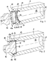
- FIG. 1 shows a closure assembly for closing an opening 10 in a body 1 in a half-section, and the body 1 is shown only schematically and may for example form the housing 1 of a door operator, which can be attached to the lintel or the door leaf of a door and for actuating the door leaf serves.
- the opening 10 is executed as an example round and extends around a longitudinal axis 21.
- an interior space 18 is formed, which is accessible through the opening 10.
- a closure element 11 and, by way of example, two sealing elements 17 are provided, wherein a first sealing element 17 is inserted in a bottom section 19 and a further sealing element 17 in the region of a contour 20 of the opening 10.
- the contour 20 forms an approximately conically outwardly opening edge region of the opening 10, starting from the bottom section 19 into the undercut region 15, which is formed by a circumferential edge 14 projecting inward in the direction of the longitudinal axis 21.
- the closure element 11 is designed with a bottom 12 and with a rim 13, and the edge 13 extends approximately at right angles out of the plane of extent of the bottom 12.
- the edge 13 is followed by a plurality of elastic portions 13a, which are designed in the form of spring tongues, and thus give the closure element 11 a crown-like shape.
- the elastic sections 13a can be inserted into the undercut area 15 behind the peripheral edge 14 with temporary elastic deformation snap.
- the positive locking arrangement of the closure element 11 in the opening 10 is in connection with the following Figures 2 and 3 shown in more detail.
- FIG. 2 the body 1 is shown with its interior 18 in a further half-section, and the opening 10 is closed with the closure element 11, while the tool 16 is still in contact with the closure element 11.
- FIG. 3 shows the body 1 with the in the opening 10 einitzenden closure element 11 according to FIG. 2 , wherein the tool 16 has been released again from the contact with the closure element 11.
- the closure element 11 is positively inserted and thus self-holding in the opening 10, and the positive connection is formed by the elastic portions 13a on the edge 13 of the closure element 11, which are snapped into the undercut region 15 behind the peripheral edge 14.
- the elastic portions 13a can slide on insertion of the closure element 11 by elastic compression in the direction of the longitudinal axis 21 along the inwardly facing peripheral edge 14 along to shown in the final position of the closure element 11 shown again snap apart, so that the manner of spring tongues formed elastic portions 13a hold the closure member 11 by engaging behind the peripheral edge 14 in the opening 10 safely.
- the closure member 11 is formed as a metallic deep-drawing member and has a bottom 12 and a rim 13 forming a first circumferential and circumferentially transmitting portion and on the portion elastic portions 13 a continue, which give the closure member 11 a crown-like shape.
- the opening 10 shows a peripheral edge 14, behind which the undercut region 15 is formed.
- the contour 20 connects, which tapers in the direction of the bottom portion 19 in diameter.
- the bottom portion 19 forms only a plane, circumferential edge, which merges in the further course of the body 1 in the interior 18.
- FIG. 4 finally shows a view of the body 1 with the opening 10, in which a closure element 11 is seated, wherein inside the closure element 11, a securing element 22 is introduced.
- the securing element 22 prevents the elastic portions 13a from being able to resiliently spring back inwards in the direction of the longitudinal axis 21.
- a securing of the closure element 11 is created in the opening 10, as ensured by the securing element 22 of the positive connection between the elastic portions 13 a and the peripheral edge 14.
- the Securing element 22 is designed such that it holds the closure element 11 in shape, which preferably comes into its own when the closure element 11 is formed from a plastic-like material and / or with thin wall thicknesses.
- the body 1 is designed as a housing and enclosing the interior 18.
- the body 1 is shown only schematically and may form the housing of a door operator, wherein the opening 10 may form an end closure opening, via which a locking mechanism is inserted into the door operator and wherein the Interior 18 may be filled with pressure oil before the opening 10 is closed with the closure member 11 in the manner described above.
- the closure element 11 does not have a flat bottom 12, this may be outwardly or preferably curved inwards, so that the opening 10 even at higher pressures still in the interior 18 of the body 1 can be securely closed by the closure member 11.
- the number and the geometrical shape of the elastic portions 13a are shown by way of example only, and the elastic portions 13a may also be punched out of a portion of the edge 13 of the closure member 11, so that the elastic portions 13a, for example, form a closed contour in the edge 13. These can then engage in the same manner in an undercut area 15 behind a peripheral edge 14. It is also conceivable not to carry out the peripheral edge 14 continuously in full but to form it with interruptions.
Description
- Die vorliegende Erfindung betrifft ein Verfahren zum Verschließen einer Öffnung in einem Körper, beispielsweise in einem Gehäuse, wofür ein Verschlusselement vorgesehen wird, das in die Öffnung eingesetzt wird.
- Eine solche zu verschließende Öffnung kann beispielsweise im Gehäuse eines Türbetätigers zur Betätigung einer Tür vorhanden sein, um einen Innenraum des Gehäuses druckdicht zu verschließen. Hierfür wird bei der Montage nach der Anordnung verschiedener mechanischer Komponenten im Innenraum des Gehäuses und nach Befüllen des Innenraums mit einem Druckmittel das Verschlusselement in der Öffnung eingesetzt, das den Innenraum des Gehäuses druckdicht verschließt. Das Verschlusselement ist dabei gewöhnlich als Verschlussschraube ausgeführt.
- Die
DE 20 2008 008 921 U1 zeigt einen Türbetätiger zur Betätigung einer Drehtür mit einem Gehäuse, in dem endseitig eine Öffnung in Form einer zylindrischen Tasche ausgebildet ist. In diese zylindrische Tasche kann eine Verschlussschraube eingeschraubt werden, um den Innenraum des Gehäuses des Türschließers druckdicht zu verschließen. - Grundsätzlich kann mit einem Verschlusselement in Form einer Schraube ein Dichtelement so vorteilhaft in der Öffnung des Körpers angebracht werden, dass eine hinreichende Dichtwirkung entsteht. Nachteilhafterweise ist jedoch sowohl am Verschlusselement als auch in der Öffnung des Körpers ein Gewinde erforderlich, das erhöhte Herstellungskosten verursacht. Zudem besteht ein weiterer Nachteil darin, dass bei der Montage des Türbetätigers der Arbeitsgang des Einschraubens der Verschlussschraube in das Gehäuse des Türbetätigers eine gewisse Zeit in Anspruch nimmt, die in Bezug auf eine Jahresmenge von Türbetätigern erhebliche Montagekosten aufkommen lässt.
- Die
DE 10 2010 017 570 A1 zeigt eine weitere Verschlussanordnung zum Verschließen einer Öffnung im Gehäuse eines Türbetätigers, und es wird als Verschlusselement die Verwendung eines gewölbten Deckels vorgeschlagen, der unter plastischer Verformung in der Öffnung angeordnet wird, um den Innenraum druckdicht zu verschließen. Der Deckel besitzt eine gewölbte Fläche, gegen die ein Werkzeug wirkt, um die gewölbte Fläche plan zu drücken. Dabei vergrößert sich der Außendurchmesser des Verschlusselementes und gelangt in eine umlaufende Nut, sodass das Verschlusselement in der Öffnung durch Eingriff in die Nut selbsthaltend angeordnet wird. Weiterführend wird vorgeschlagen, vor dem Einsetzen des Verschlusselementes ein Dichtelement in die Nut einzubringen, sodass nach plastischer Verformung der gewölbten Fläche des Deckels das Dichtelement dichtend in der Nut einsitzt, in die unter radialer Aufweitung auch der Außenrand des Verschlusselementes eingerückt ist. - Bei Aufbau eines erhöhten Innendrucks im Innenraum des Gehäuses des Türbetätigers kann jedoch das Verschlusselement nicht sicher in der Öffnung des Körpers halten, und es können Leckagen entstehen, die zu einem Druckverlust im Innenraum des Gehäuses führen können und folglich zu vermeiden sind. Wird ein plastisch verformbares Verschlusselement mit einer mittigen, gewölbten Fläche in Form eines Deckels vorgesehen, so kann gegebenenfalls keine hinreichende Dichtwirkung erzielt werden.
- Aufgabe der Erfindung ist die Schaffung eines einfachen Verfahrens zum Verschließen einer Öffnung in einem Körper sowie eine Verschlussanordnung hierzu, wobei die Öffnung mit dem Verfahren bzw. durch die Verschlussanordnung auf einfache Weise druckdicht verschlossen wird.
- Diese Aufgabe wird ausgehend von einem Verfahren zum Verschließen einer Öffnung in einem Körper gemäß dem Oberbegriff des Anspruches 1, ausgehend von einer Verschlussanordnung zum Verschließen der Öffnung gemäß dem Oberbegriff des Anspruches 8 sowie ausgehend von einem Türbetätiger gemäß Anspruch 12 mit den jeweils kennzeichnenden Merkmalen gelöst. Vorteilhafte Weiterbildungen der Erfindung sind in den abhängigen Ansprüchen angegeben.
- Erfindungsgemäß sieht das Verfahren zunächst die Bereitstellung des Verschlusselementes mit einem Boden und mit einem sich aus der Erstreckungsebene des Bodens abstreckenden Rand vor, wobei der Rand mehrere elastische Abschnitte aufweist, und wobei ferner die Ausbildung der Öffnung mit einer in die Öffnung einragenden Umlaufkante vorgesehen ist, hinter der ein Hinterschneidungsbereich gebildet wird und es ist das Fügen des Verschlusselementes in die Öffnung so vorgesehen, sodass der Boden nach innen weist und schließlich umfasst das Verfahren den Schritt des elastischen Einschnappens der elastischen Abschnitte des Randes in den Hinterschneidungsbereich.
- Durch die erfindungsgemäße Ausführung des Verschlusselementes zur formschlüssigen Anordnung in der Öffnung entsteht der Vorteil, dass das Verschlusselement auf einfache Weise in der Öffnung angeordnet werden kann, wobei die Verschlussanordnung durch das Verschlusselement bereits druckdicht ausgeführt werden kann. Baut sich im Innenraum des Körpers ein Überdruck auf, so wirkt dieser gegen den Boden des Verschlusselementes, und der in den Hinterschneidungsbereich geführte Rand des Verschlusselementes leitet die durch den Druck in den Boden eingeleitete Kraft über die elastischen Abschnitte in die Umlaufkante der Öffnung ab. Die Umlaufkante kann die Öffnung im Körper nach außen beranden, sodass das Verschlusselement in der Öffnung vollständig formschlüssig einsitzt.
- Im nicht elastisch verformten Zustand der elastischen Abschnitte weist der Rand, der im Außendurchmesser bestimmt sein kann durch die elastischen Abschnitte, einen größeren Durchmesser auf als die in die Öffnung leicht einragende Umlaufkante, um den Hinterschneidungsbereich zu bilden. Wird das Verschlusselement in die Öffnung eingedrückt, so verformen sich die elastischen Abschnitte derart, dass diese zur Mitte des Verschlusselementes hin elastisch verformt werden. Wurde das Verschlusselement soweit in die Öffnung eingerückt, dass die elastischen Abschnitte hinter die Umlaufkante in den Hinterschneidungsbereich einschnappen können, so gelangen die elastischen Abschnitte durch ihre Rückfederwirkung wieder von der Mitte des Verschlusselementes weg in den Hinterschneidungsbereich, wodurch das formschlüssige Einsitzen des Verschlusselementes in der Öffnung erreicht wird.
- Die Öffnung im Körper kann vorzugsweise rotationssymmetrisch ausgeführt sein. Neben einer runden Öffnung kann diese jedoch durch jede weitere, beliebige Form bestimmt sein. Beispielsweise kann diese Form elliptisch, dreieckig, viereckig, insbesondere rechteckig oder vieleckig ausgeführt sein. Die Form des Verschlusselementes kann dabei der Form der Öffnung angepasst sein. Das Einführen des Randes mit den elastischen Abschnitten in den Hinterschneidungsbereich der Öffnung bleibt dabei von der Konturform der Öffnung unbeeinflusst.
- Nach einer möglichen Ausführungsform zur Bildung des Verschlusselementes können die elastischen Abschnitte beispielsweise durch Federzungen gebildet sein, die am Rand angeformt sind. Die Federzungen werden beim Einfügen des Verschlusselementes in die Öffnung gleichzeitig elastisch verformt, insbesondere zur Mitte des Verschlusselementes nach innen in Richtung einer Längsachse, aus der das Verschlusselement in die Öffnung geführt wird, und um die sich das Verschlusselement herum erstreckt, derart, dass die Längsachse eine Flächennormale auf den Boden des Verschlusselementes bildet. Die Federzungen können den äußeren Rand des Verschlusselementes so beranden, dass diese eine Art Zacken einer Krone bilden, die in Richtung zur Längsachse elastisch verformt werden können. Dabei können einzelne, wenige elastische Abschnitte am Rand des Verschlusselementes vorgesehen sein, und es ist von Vorteil, wenigstens zwei elastische Abschnitte vorzusehen. Vorzugsweise sind jedoch mehrere insbesondere über dem Umfang des Verschlusselementes gleich verteilte elastische Abschnitte vorgesehen. Nach einer weiteren Ausführungsform können die elastischen Abschnitte auch nach Art von Federzungen ausgebildet sein, die aus einem umlaufenden Rand des Verschlusselementes ausgeklinkt sind, beispielsweise durch ein Stanz-Biegeverfahren. Ferner besteht die Möglichkeit, den Rand des Verschluss-elementes, der sich um den Boden herum erstreckt, lediglich geschlitzt auszuführen, sodass durch den geschlitzten Rand einzelne elastische Abschnitte gebildet werden.
- Mit besonderem Vorteil kann das Einschnappen des Verschlusselementes in die Öffnung durch ein bereitgestelltes Werkzeug vorgenommen werden, mit dem das Verschlusselement durch Aufbringen einer Fügekraft auf den Boden des Verschlusselementes in die Öffnung eingedrückt wird, bis die elastischen Abschnitte in den Hinterschneidungsbereich eingeschnappt sind. Das Werkzeug kann einen kleineren Durchmesser aufweisen als die Innenseite des Randes, um das vorübergehende elastische Einfedern der elastischen Abschnitte in Richtung zur Mitte des Verschlusselementes nicht zu behindern. Auf gleiche Weise kann das Verschlusselement auch manuell in die Öffnung eingefügt werden, sofern die Fügekräfte zum Einschnappen der elastischen Abschnitte in den Hinterschneidungsbereich von Hand aufgebracht werden können.
- Um eine hinreichende Abdichtung der Öffnung durch das Verschlusselement zu erreichen, kann das Verfahren die Bereitstellung eines Dichtelementes umfassen, das vor dem Fügen des Verschlusselementes in der Öffnung eingesetzt wird. Insbesondere können zwei oder mehrere Dichtelemente vorgesehen sein, die vor dem Fügen des Verschlusselementes in der Öffnung eingesetzt werden. Die Öffnung kann hierfür eine sich an die Umlaufkante nach innen anschließende Kontur aufweisen, die etwa der Kontur des Randes des Verschlusselementes entspricht, sodass sich die elastischen Abschnitte an die Außenkontur anlegen können. Beispielsweise kann die sich anschließende Kontur einen Kegelabschnitt bilden, und das Dichtelement kann in der unteren Kehle des Kegelabschnittes in Übergang an einen Bodenabschnitt der Öffnung eingesetzt werden. Alternativ kann das Dichtelement auch als Dichtband ausgeführt sein, das der Kontur zwischen dem Bodenabschnitt und der Umlaufkante angepasst ist, und ebenfalls kann dieses vor dem Fügen des Verschlusselementes in der Öffnung eingesetzt werden.
- Ist das Dichtelement als O-Ringdichtung ausgeführt, so kann dieses entweder im Übergang des Bodenabschnittes zur Außenkontur oder im Hinterschneidungsbereich eingesetzt werden, sodass das Dichtband zwischen dem Rand und der Umlaufkante in den Hinterschneidungsbereich eingepresst wird. Auch ist es denkbar, in der Kontur der Öffnung eine Nut einzubringen, beispielsweise durch ein spanendes Verfahren, in die ein beispielsweise O-ringförmiges Dichtelement oder ein Dichtband eingesetzt werden kann. Insbesondere kann der Rand des Verschlusselementes einen nicht unterbrochenen, umlaufenden Abschnitt aufweisen, und wird das Verschlusselement eingesetzt, kann der umlaufende Bereich des Randes durch ein Andrücken gegen das Dichtelement die Öffnung im Körper abdichten.
- Das Verfahren bietet den Vorteil einer einfachen Herstellung der Verschlussanordnung, wobei bereits die Mittel zum Verschluss der Öffnung auf einfache Weise hergestellt werden können. Beispielsweise kann das Verschlusselement mit dem Boden und dem Rand, der die elastischen Abschnitte aufweist, tiefgezogen und/oder im Scherschnitt berandet werden, um dieses mit dem Boden und dem beispielsweise teilweise umlaufenden Rand sowie den elastischen Abschnitten auszubilden. Beim Tiefziehen kann der Rand aus dem zunächst planen Blech aus dem Randbereich des Bodens abgestreckt werden, beispielsweise unter Bildung eines zylindrischen Abschnittes, an den sich die elastischen Abschnitte nach Art von mehreren, gleich beabstandeten und zueinander gleich ausgebildeten Federzungen anschließen. Auch ist es vorteilhaft, dass die Öffnung und die die Öffnung berandende Umlaufkante mit dem Hinterschneidungsbereich im Körper durch ein Gussverfahren oder durch ein spanendes Verfahren eingebracht wird.
- Das Verfahren zur Bildung einer Verschlussanordnung zum Verschließen einer Öffnung in einem Körper kann besonders vorteilhaft zum Verschließen des Gehäuses eines Türbetätigers angewendet werden. Dabei bildet das Gehäuse des Türbetätigers den Körper mit der Öffnung, wobei durch das Verschlusselement ein insbesondere mit einem Druckmittel befüllter Innenraum des Türbetätigers druckdicht verschlossen wird. Das Verschlusselement und die erfindungsgemäße Anordnung des Verschlusselementes in der Öffnung kann dabei eine Verschlussschraube ersetzen, die die Öffnung gewöhnlich verschließt und in diese eingeschraubt werden muss.
- Um das Verschlusselement in der Öffnung zu sichern, kann in das Verschlusselement ein Sicherungselement eingesetzt werden, das ein elastisches Rückfedern der elastischen Abschnitte des Randes aus dem formschlüssigen Eingriff im Hinterschneidungsbereich verhindert. Das Sicherungselement kann mit besonderem Vorteil selbsthaltend am Verschlusselement, insbesondere innenseitig an den elastischen Abschnitten des Randes, angeordnet werden. Insbesondere kann das Sicherungselement das Verschlusselement optisch verdecken, sodass dieses von der Außenseite des Körpers, insbesondere des Gehäuses eines Türbetätigers, nicht sichtbar ist. Insbesondere kann das Sicherungselement mit der Außenseite des Körpers, insbesondere mit der Außenseite des Gehäuses des Türbetätigers, plan abschließen.
- Die vorliegende Erfindung richtet sich ferner auf eine Verschlussanordnung zum Verschließen einer Öffnung in einem Körper, beispielsweise in einem Gehäuse, wobei ein Verschlusselement zum Einsetzen in die Öffnung vorgesehen ist, und wobei das Verschlusselement mit einem Boden und mit einem sich aus der Erstreckungsebene des Bodens abstreckenden Rand ausgebildet ist, wobei der Rand mehrere elastische Abschnitte aufweist und wobei die Öffnung eine in diese einragende Umlaufkante aufweist, hinter der ein Hinterschneidungsbereich gebildet ist. Dabei wird erfindungsgemäß das Verschlusselement mit dem Boden nach innen weisend in die Öffnung eingefügt und die elastischen Abschnitte des Randes können elastisch in den Hinterschneidungsbereich eingeschnappt sein. Von der Außenseite der Öffnung im Körper ist folglich das Verschlusselement mit dem Boden und dem Rand sowie gegebenenfalls mit den elastischen Abschnitten sichtbar, wobei der Boden nach innen in die Öffnung weist und wobei sich der Rand insbesondere mit den elastischen Abschnitten gegen den Hinterschneidungsbereich der Öffnung abstützt, die durch eine nach innen weisende Umlaufkante in Erscheinung tritt.
- Die elastischen Abschnitte am Rand des Verschlusselementes oder als Bestandteil des Randes des Verschlusselementes können durch Federzungen gebildet sein, sodass das Verschlusselement durch die elastischen Abschnitte eine kronenartige Gestalt erlangt. Das Abstützen der Federzungen gegen die Umlaufkante, wenn diese in den Hinterschneidungsbereich elastisch eingeschnappt sind, erfolgt insbesondere mit den Kopfbereichen der Federzungen, das heißt mit ihren Enden.
- Zwischen der Öffnung und dem Verschlusselement kann ein Dichtelement angeordnet sein, das insbesondere als O-Ringdichtung ausgebildet ist. Alternativ kann die Verschlussanordnung ein Dichtband aufweisen, das sich im Bereich der Kontur zwischen der Umlaufkante und dem Bodenabschnitt der Öffnung erstreckt und den Rand des Verschlusselementes außenseitig umschließt.
- Insbesondere kann der Körper durch das Gehäuse eines Türbetätigers gebildet sein, wobei durch das Verschlusselement ein insbesondere mit einem Druckmittel befüllter Innenraum des Türbetätigers druckdicht verschlossen ist.
- Die vorliegende Erfindung richtet sich ferner auf einen Türbetätiger mit einem Gehäuse, in dem eine Öffnung eingebracht ist und wobei ein Verschlusselement zum Einsetzen in die Öffnung vorgesehen ist, und wobei das Verschlusselement mit einem Boden und mit einem sich aus der Erstreckungsebene des Bodens abstreckenden Rand ausgebildet ist, wobei der Rand mehrere elastische Abschnitte aufweist und wobei die Öffnung eine in diese einragende Umlaufkante aufweist, hinter der ein Hinterschneidungsbereich gebildet ist, wobei das Verschlusselement mit dem Boden nach innen weisend in die Öffnung eingefügt ist und wobei die elastischen Abschnitte des Randes elastisch in den Hinterschneidungsbereich eingeschnappt sind. Die weiteren Merkmale, die in Zusammenhang mit dem Verfahren zum Verschließen der Öffnung im Körper beschrieben sind, sowie die zugeordneten Vorteile, die mit den weiteren Merkmalen einhergehen, finden für den erfindungsgemäßen Türbetätiger selbstverständlich ebenfalls Berücksichtigung.
- Weitere, die Erfindung verbessernde Maßnahmen werden nachstehend gemeinsam mit der Beschreibung eines bevorzugten Ausführungsbeispiels der Erfindung anhand der Figuren näher dargestellt. Es zeigt:
- Figur 1
- eine Ansicht des Körpers mit der Öffnung, die sich in einem nicht verschlossenen Zustand befindet, wobei vor der Öffnung ein Verschlusselement und ein Werkzeug zum Einfügen des Verschlusselementes in die Öffnung gezeigt ist,
- Figur 2
- eine Ansicht des Körpers mit dem in die Öffnung eingesetzten Verschlusselement, während sich das Werkzeug noch in Kontakt mit dem Verschlusselement befindet,
- Figur 3
- die Ansicht des Körpers mit dem eingesetzten Verschlusselement gemäß
Figur 2 , wobei das Werkzeug vom Verschlusselement wieder entnommen ist und - Figur 4
- eine Ansicht des Körpers mit der durch das Verschlusselement verschlossenen Öffnung, wobei im Verschlusselement ein Sicherungselement eingesetzt ist.
-
Figur 1 zeigt eine Verschlussanordnung zum Verschließen einer Öffnung 10 in einem Körper 1 in einem Halbschnitt, und der Körper 1 ist lediglich schematisch gezeigt und kann beispielsweise das Gehäuse 1 eines Türbetätigers bilden, der am Türsturz oder am Türblatt einer Tür befestigt werden kann und zur Betätigung des Türblattes dient. - Die Öffnung 10 ist beispielhaft rund ausgeführt und erstreckt sich um eine Längsachse 21. Im Körper 1 ist ein Innenraum 18 ausgebildet, der durch die Öffnung 10 zugänglich ist.
- Zur Ausführung des Verfahrens zum Verschließen der Öffnung 10 werden ein Verschlusselement 11 und beispielhaft zwei Dichtelemente 17 bereitgestellt, wobei ein erstes Dichtelement 17 in einem Bodenabschnitt 19 und ein weiteres Dichtelement 17 im Bereich einer Kontur 20 der Öffnung 10 eingesetzt ist. Die Kontur 20 bildet dabei einen etwa kegelförmig sich nach außen öffnenden Randbereich der Öffnung 10 beginnend vom Bodenabschnitt 19 bis in den Hinterschneidungsbereich 15, der durch eine nach innen in Richtung der Längsachse 21 einragende Umlaufkante 14 gebildet ist.
- Das Verschlusselement 11 ist mit einem Boden 12 und mit einem Rand 13 ausgeführt, und der Rand 13 erstreckt sich etwa rechtwinklig aus der Erstreckungsebene des Bodens 12 heraus. An den Rand 13 schließen sich mehrere elastische Abschnitte 13a an, die in Form von Federzungen ausgeführt sind, und so dem Verschlusselement 11 eine kronenartige Gestalt verleihen.
- Wird mit dem Werkzeug 16 das Verschlusselement 11 in die Öffnung 10 eingedrückt, indem eine Fügekraft F über das Werkzeug 16 in den Boden 12 des Verschlusselementes 11 eingeleitet wird, so können unter vorübergehender elastischer Verformung die elastischen Abschnitte 13a in den Hinterschneidungsbereich 15 hinter der Umlaufkante 14 einschnappen. Dadurch, dass die elastischen Abschnitte 13a sich wieder radial aufweiten und somit ihren Abstand zur Längsachse 21 wieder vergrößern, können diese nach Einschnappen in den Hinterschneidungsbereich 15 durch ein innenseitiges Anstoßen gegen die Umlaufkante 14 über ihre Enden einen Formschluss zwischen dem Verschlusselement 11 und der Öffnung 10 im Körper 1 herstellen. Die formschlüssige Anordnung des Verschlusselementes 11 in der Öffnung 10 ist in Verbindung mit den folgenden
Figuren 2 und3 näher dargestellt. - In
Figur 2 ist der Körper 1 mit seinem Innenraum 18 in einem weiteren Halbschnitt gezeigt, und die Öffnung 10 ist mit dem Verschlusselement 11 verschlossen, während sich das Werkzeug 16 noch in Kontakt mit dem Verschlusselement 11 befindet.Figur 3 zeigt den Körper 1 mit dem in der Öffnung 10 einsitzenden Verschlusselement 11 gemäßFigur 2 , wobei das Werkzeug 16 wieder aus dem Kontakt mit dem Verschlusselement 11 gelöst wurde. Das Verschlusselement 11 ist formschlüssig und damit selbsthaltend in der Öffnung 10 eingesetzt, und der Formschluss entsteht durch die elastischen Abschnitte 13a am Rand 13 des Verschlusselementes 11, die in den Hinterschneidungsbereich 15 hinter der Umlaufkante 14 eingeschnappt sind. Die elastischen Abschnitte 13a können beim Einfügen des Verschlusselementes 11 durch elastisches Einfedern in Richtung zur Längsachse 21 an der nach innen weisenden Umlaufkante 14 entlang gleiten, um im gezeigten endgültigen Sitz des Verschlusselementes 11 wieder auseinander zu schnappen, sodass die nach Art von Federzungen ausgebildeten elastischen Abschnitte 13a das Verschlusselement 11 durch Hintergreifen der Umlaufkante 14 in der Öffnung 10 sicher halten. - Durch den Kontakt der Dichtelemente 17 mit dem Verschlusselement 11, die im Bodenabschnitt 19 sowie in der Kontur 20 der Öffnung 10 eingebracht sind, entsteht ein druckdichter Verschluss der Öffnung 10, sodass der Innenraum 18 beispielsweise mit einem Druckmittel unter Druck gesetzt werden kann, ohne dass das Druckmittel aus der Öffnung 10 entweichen kann.
- Das Verschlusselement 11 ist als metallisches Tiefziehbauteil ausgebildet und besitzt einen Boden 12 und einen Rand 13, der einen ersten umlaufenden und in Umfangsrichtung durchgebenden Abschnitt bildet und an dem Abschnitt setzen sich elastische Abschnitte 13a fort, die dem Verschlusselement 11 eine kronenartige Gestalt verleihen. Die Öffnung 10 zeigt eine Umlaufkante 14, hinter der der Hinterschneidungsbereich 15 ausgebildet ist. An den Hinterschneidungsbereich 15 schließt sich die Kontur 20 an, die sich in Richtung des Bodenabschnittes 19 im Durchmesser verjüngt. Der Bodenabschnitt 19 bildet dabei lediglich einen planen, umlaufenden Rand, der im weiteren Verlauf des Körpers 1 in den Innenraum 18 übergeht.
-
Figur 4 zeigt schließlich eine Ansicht des Körpers 1 mit der Öffnung 10, in der ein Verschlusselement 11 einsitzt, wobei innenseitig im Verschlusselement 11 ein Sicherungselement 22 eingebracht ist. Das Sicherungselement 22 verhindert, dass die elastischen Abschnitte 13a wieder nach innen in Richtung zur Längsachse 21 elastisch rückfedern können. Dadurch wird eine Sicherung des Verschlusselementes 11 in der Öffnung 10 geschaffen, da durch das Sicherungselement 22 der Formschluss zwischen den elastischen Abschnitten 13a und der Umlaufkante 14 sichergestellt bleibt. Das Sicherungselement 22 ist derart ausgebildet, dass es das Verschlusselement 11 in Form hält, welches vorzugsweise dann zur Geltung kommt, wenn das Verschlusselement 11 aus einem kunststoffartigen Werkstoff und/oder mit dünnen Wandstärken ausgebildet ist. - In Zusammenhang mit den
Figuren 1 bis 4 ist der Körper 1 als Gehäuse ausgeführt und umschließt den Innenraum 18. Der Körper 1 ist lediglich schematisch gezeigt und kann das Gehäuse eines Türbetätigers bilden, wobei die Öffnung 10 eine endseitige Verschlussöffnung bilden kann, über die eine Schließmechanik in den Türbetätiger eingesetzt wird und wobei der Innenraum 18 mit Drucköl aufgefüllt sein kann, bevor die Öffnung 10 mit dem Verschlusselement 11 auf vorstehend beschriebene Weise verschlossen wird. - Die Erfindung beschränkt sich in ihrer Ausführung nicht auf das vorstehend angegebene bevorzugte Ausführungsbeispiel. Vielmehr ist eine Anzahl von Varianten denkbar, welche von der dargestellten Lösung auch bei grundsätzlich anders gearteten Ausführungen Gebrauch macht. Sämtliche aus den Ansprüchen, der Beschreibung oder den Zeichnungen hervorgehenden Merkmale und/oder Vorteile, einschließlich konstruktiver Einzelheiten oder räumliche Anordnungen, können sowohl für sich als auch in den verschiedensten Kombinationen erfindungswesentlich sein. Beispielsweise muss das Verschlusselement 11 keinen plan ausgebildeten Boden 12 aufweisen, dieser kann nach außen oder vorzugsweise nach innen gewölbt ausgeführt sein, sodass die Öffnung 10 auch bei höheren Drücken noch im Innenraum 18 des Körpers 1 durch das Verschlusselement 11 sicher verschlossen werden kann. Die Anzahl und die geometrische Gestalt der elastischen Abschnitte 13a ist lediglich beispielhaft gezeigt, und die elastischen Abschnitte 13a können ebenso aus einem Bereich des Randes 13 des Verschlusselementes 11 ausgestanzt sein, sodass die elastischen Abschnitte 13a beispielsweise eine geschlossene Kontur im Rand 13 bilden. Diese können dann auf gleiche Weise in einen Hinterschneidungsbereich 15 hinter einer Umlaufkante 14 einrasten. Ebenfalls ist es denkbar, die Umlaufkante 14 nicht durchgehend vollumfänglich auszuführen sondern mit Unterbrechungen auszubilden.
-
- 1
- Körper, Gehäuse
- 10
- Öffnung
- 11
- Verschlusselement
- 12
- Boden
- 13
- Rand
- 13a
- elastischer Abschnitt
- 14
- Umlaufkante
- 15
- Hinterschneidungsbereich
- 16
- Werkzeug
- 17
- Dichtelement
- 18
- Innenraum
- 19
- Bodenabschnitt
- 20
- Kontur
- 21
- Längsachse
- 22
- Sicherungselement
- F
- Fügekraft
Claims (13)
- Verfahren zum Verschließen einer Öffnung (10) in einem Körper (1), beispielsweise in einem Gehäuse (1), wofür ein Verschlusselement (11) vorgesehen wird, das in die Öffnung (10) eingesetzt wird, gekennzeichnet durch folgende Schritte:- Bereitstellen des Verschlusselementes (11) mit einem Boden (12) und mit einem sich aus der Erstreckungsebene des Bodens (12) abstreckenden Rand (13), wobei der Rand (13) mehrere elastische Abschnitte (13a) aufweist,- Ausbilden der Öffnung (10) mit einer in die Öffnung (10) einragenden Umlaufkante (14), hinter der ein Hinterschneidungsbereich (15) gebildet wird,- Fügen des Verschlusselementes (11) in die Öffnung (10), sodass der Boden (12) nach innen weist und- elastisches Einschnappen der elastischen Abschnitte (13a) des Randes (13) in den Hinterschneidungsbereich (15).
- Verfahren nach Anspruch 1, dadurch gekennzeichnet, dass die elastischen Abschnitte (13a) durch Federzungen (13a) gebildet sind, die am Rand (13) angeformt sind.
- Verfahren nach Anspruch 1 oder 2, dadurch gekennzeichnet, dass ein Werkzeug (16) bereitgestellt wird, mit dem das Verschlusselement (11) durch Aufbringen einer Fügekraft (F) auf den Boden (12) des Verschlusselementes (11) in die Öffnung (10) eingedrückt wird, bis die elastischen Abschnitte (13a) in den Hinterschneidungsbereich (15) eingeschnappt sind.
- Verfahren nach einem der Ansprüche 1 bis 3, dadurch gekennzeichnet, dass wenigstens ein Dichtelement (17) bereitgestellt wird, das vor dem Fügen des Verschlusselementes (11) in der Öffnung (10) eingesetzt wird.
- Verfahren nach einem der vorgenannten Ansprüche, dadurch gekennzeichnet, dass zum Bereitstellen des Verschlusselementes (11) ein Blech durch Stanz- und/oder Biegeverfahren bearbeitet wird, um dieses mit dem Boden (12) und dem Rand (13) mit den elastischen Abschnitten (13a) auszuführen und/oder dass die die Öffnung (10) berandende Umlaufkante (14) mit dem Hinterschneidungsbereich (15) im Körper (1) durch ein Gussverfahren oder durch ein spanendes Verfahren eingebracht wird.
- Verfahren nach einem der vorgenannten Ansprüche, dadurch gekennzeichnet, dass der Körper (1) durch das Gehäuse (1) eines Türbetätigers gebildet wird, wobei durch das Verschlusselement (11) ein insbesondere mit einem Druckmittel befüllter Innenraum (18) des Türbetätigers druckdicht verschlossen wird.
- Verfahren nach einem der vorgenannten Ansprüche, dadurch gekennzeichnet, dass in das Verschlusselement (11) ein Sicherungselement (22) eingesetzt wird, das ein elastisches Rückfedern der elastischen Abschnitte (13a) des Randes (13) aus dem formschlüssigen Eingriff im Hinterschneidungsbereich (15) verhindert.
- Verschlussanordnung zum Verschließen einer Öffnung (10) in einem Körper (1), beispielsweise in einem Gehäuse (1), wobei ein Verschlusselement (11) zum Einsetzen in die Öffnung (10) vorgesehen ist, dadurch gekennzeichnet,- dass das Verschlusselement (11) mit einem Boden (12) und mit einem sich aus der Erstreckungsebene des Bodens (12) abstreckenden Rand (13) ausgebildet ist, wobei der Rand (13) mehrere elastische Abschnitte (13a) aufweist und- dass die Öffnung (10) eine in diese einragende Umlaufkante (14) aufweist, hinter der ein Hinterschneidungsbereich (15) gebildet ist,- wobei das Verschlusselement (11) mit dem Boden (12) nach innen weisend in die Öffnung (10) eingefügt ist und wobei die elastischen Abschnitte (13a) des Randes (13) elastisch in den Hinterschneidungsbereich (15) eingeschnappt sind.
- Verschlussanordnung nach Anspruch 8, dadurch gekennzeichnet, dass die elastischen Abschnitte (13a) durch Federzungen (13a) gebildet sind und den äußeren Bereich des Randes (13) bilden, sodass das Verschlusselement (11) durch die elastischen Abschnitte (13a) eine kronenartige Gestalt erlangt.
- Verschlussanordnung nach Anspruch 8 oder 9, dadurch gekennzeichnet, dass zwischen der Öffnung (10) und dem Verschlusselement (11) ein Dichtelement (17) angeordnet ist, das insbesondere als O- Ringdichtung ausgebildet ist.
- Verschlussanordnung nach einem der Ansprüche 8 bis 10, dadurch gekennzeichnet, dass der Körper (1) durch das Gehäuse (1) eines Türbetätigers gebildet ist, wobei durch das Verschlusselement (11) ein insbesondere mit einem Druckmittel befüllter Innenraum (18) des Türbetätigers druckdicht verschlossen ist.
- Türbetätiger mit einem Gehäuse (1) und mit einer Verschlussanordnung nach Anspruch 8.
- Türbetätiger nach Anspruch 12 mit einer Verschlussanordnung gemäß einem der Ansprüche 9 bis 11.
Applications Claiming Priority (1)
| Application Number | Priority Date | Filing Date | Title |
|---|---|---|---|
| DE102012111923.6A DE102012111923A1 (de) | 2012-12-07 | 2012-12-07 | Verfahren zum Verschließen einer Öffnung in einem Körper, insbesondere in einem Türbetätiger |
Publications (2)
| Publication Number | Publication Date |
|---|---|
| EP2740874A1 EP2740874A1 (de) | 2014-06-11 |
| EP2740874B1 true EP2740874B1 (de) | 2019-10-09 |
Family
ID=49641458
Family Applications (1)
| Application Number | Title | Priority Date | Filing Date |
|---|---|---|---|
| EP13005402.6A Active EP2740874B1 (de) | 2012-12-07 | 2013-11-18 | Verfahren und anordnung zum verschliessen einer öffnung in einem körper, insbesondere in einem türbetätiger |
Country Status (3)
| Country | Link |
|---|---|
| EP (1) | EP2740874B1 (de) |
| CN (1) | CN103867059B (de) |
| DE (1) | DE102012111923A1 (de) |
Families Citing this family (5)
| Publication number | Priority date | Publication date | Assignee | Title |
|---|---|---|---|---|
| FR2998937B1 (fr) | 2012-12-03 | 2016-04-01 | Jtekt Europe Sas | Réducteur a engrenage avec bouchon d'étanchéité assurant le maintien axial d'un ressort de rattrapage du jeu d'engrènement. |
| DE102013113092A1 (de) * | 2013-11-27 | 2015-05-28 | Dorma Deutschland Gmbh | Türschließvorrichtung |
| DE102013022159B3 (de) * | 2013-12-19 | 2014-12-04 | Geze Gmbh | Türschließer |
| DE102018114267A1 (de) * | 2018-06-14 | 2019-12-19 | Thyssenkrupp Ag | Elektromechanische Servolenkung mit einem Schraubradgetriebe und einem Getriebegehäuse |
| FR3121907A1 (fr) * | 2021-04-15 | 2022-10-21 | Jtekt Europe | Procédé de fixation d’un couvercle sur un orifice d’un système de direction assistée et un tel couvercle |
Family Cites Families (7)
| Publication number | Priority date | Publication date | Assignee | Title |
|---|---|---|---|---|
| CN1078658C (zh) * | 1997-08-01 | 2002-01-30 | 盖慈有限公司 | 门扇驱动器 |
| DE102006024767B4 (de) * | 2006-05-27 | 2010-07-29 | Zf Lenksysteme Gmbh | Verfahren und Vorrichtung zum Verbinden eines Kunststoffdeckels mit einem Metallgehäuse |
| DE202008008921U1 (de) | 2008-07-03 | 2008-09-04 | Dorma Gmbh + Co. Kg | Kunststofftürschließer mit eingelegten Metallteilen |
| DE102010010544A1 (de) * | 2010-03-05 | 2011-09-08 | Dorma Gmbh + Co. Kg | Ringfilter mit einer verbesserten Dichtung |
| DE102010013072A1 (de) * | 2010-03-26 | 2011-09-29 | Dorma Gmbh + Co. Kg | Vorrichtung zum Öffnen und/oder Schließen einer Tür |
| DE102010017570A1 (de) | 2010-06-24 | 2011-12-29 | Dorma Gmbh + Co. Kg | Türbetätiger und Verfahren zur Herstellung |
| DE102010017683A1 (de) * | 2010-07-01 | 2012-01-05 | Dorma Gmbh + Co. Kg | Verschlussstopfen |
-
2012
- 2012-12-07 DE DE102012111923.6A patent/DE102012111923A1/de active Pending
-
2013
- 2013-11-18 EP EP13005402.6A patent/EP2740874B1/de active Active
- 2013-12-09 CN CN201310659600.4A patent/CN103867059B/zh active Active
Non-Patent Citations (1)
| Title |
|---|
| None * |
Also Published As
| Publication number | Publication date |
|---|---|
| CN103867059B (zh) | 2017-10-03 |
| CN103867059A (zh) | 2014-06-18 |
| EP2740874A1 (de) | 2014-06-11 |
| DE102012111923A1 (de) | 2014-06-12 |
Similar Documents
| Publication | Publication Date | Title |
|---|---|---|
| EP1893903B1 (de) | Pressfitting für ein rohr | |
| DE102008029236B3 (de) | Verbindungselement mit einer Schraube und einer daran unverlierbar angeordneten Hülse | |
| EP2740874B1 (de) | Verfahren und anordnung zum verschliessen einer öffnung in einem körper, insbesondere in einem türbetätiger | |
| EP3309414B1 (de) | Funktionselement zur fluiddichten anbringung an ein blechteil, zusammenbauteil und verfahren | |
| EP2748510B1 (de) | Verschlusselement für innendruckbeanspruchte bohrungen | |
| DE102007008066A1 (de) | Fitting und Verbindungsanordnung mit einem Fitting | |
| EP1319451A1 (de) | Stutzen für ein Wandteil, insbesondere für ein Wandteil eines Deckels oder Behälters | |
| WO2002042676A1 (de) | Anschlussvorrichtung für eine fluidleitung | |
| EP1749167B1 (de) | Verfahren zur herstellung einer steckverbindung | |
| EP3114378B1 (de) | Dichtung | |
| EP3265713B1 (de) | Steckverbinderbaugruppe zum verbinden von leitungen | |
| WO2007107174A1 (de) | Baueinheit für ein abgabeventil für die abgabe von unter druck stehenden flüssigkeiten, und behälter mit einer derartigen baueinheit | |
| DE69915291T2 (de) | Abgabevorrichtung für fliessfähige Produkte | |
| EP2635838B1 (de) | Element, vorzugsweise ein verschlusselement | |
| DE202006000743U1 (de) | Federstützelement mit daran angebundener Schraubenfeder | |
| DE102007053417A1 (de) | Elektromagnetischer Schalter für E-Maschine | |
| EP2906372B1 (de) | Verfahren zum verschliessen einer öffnung in einem türbetätiger | |
| DE10146148B4 (de) | Verschließen von Bohrungen mit in diese einsetzbaren Verschlußdeckeln | |
| DE10254999B4 (de) | Montageeinheit | |
| EP2792918A1 (de) | Stellgerät für eine verfahrenstechnische Anlage | |
| DE60107178T2 (de) | Elastisches Gelenk für einen Stossdämpfer and Stossdämpfer mit einem solchen Gelenk | |
| DE102019117086A1 (de) | Befestigungseinheit | |
| EP1890069A2 (de) | Steckverbindung | |
| DE10257818A1 (de) | Stutzen für eine Behälterwand | |
| EP3626950B1 (de) | Ventil sowie verfahren zum herstellen eines ventils |
Legal Events
| Date | Code | Title | Description |
|---|---|---|---|
| PUAI | Public reference made under article 153(3) epc to a published international application that has entered the european phase |
Free format text: ORIGINAL CODE: 0009012 |
|
| 17P | Request for examination filed |
Effective date: 20131118 |
|
| AK | Designated contracting states |
Kind code of ref document: A1 Designated state(s): AL AT BE BG CH CY CZ DE DK EE ES FI FR GB GR HR HU IE IS IT LI LT LU LV MC MK MT NL NO PL PT RO RS SE SI SK SM TR |
|
| AX | Request for extension of the european patent |
Extension state: BA ME |
|
| R17P | Request for examination filed (corrected) |
Effective date: 20141211 |
|
| RBV | Designated contracting states (corrected) |
Designated state(s): AL AT BE BG CH CY CZ DE DK EE ES FI FR GB GR HR HU IE IS IT LI LT LU LV MC MK MT NL NO PL PT RO RS SE SI SK SM TR |
|
| RAP1 | Party data changed (applicant data changed or rights of an application transferred) |
Owner name: DORMA DEUTSCHLAND GMBH |
|
| RAP1 | Party data changed (applicant data changed or rights of an application transferred) |
Owner name: DORMAKABA DEUTSCHLAND GMBH |
|
| GRAP | Despatch of communication of intention to grant a patent |
Free format text: ORIGINAL CODE: EPIDOSNIGR1 |
|
| STAA | Information on the status of an ep patent application or granted ep patent |
Free format text: STATUS: GRANT OF PATENT IS INTENDED |
|
| INTG | Intention to grant announced |
Effective date: 20190429 |
|
| GRAS | Grant fee paid |
Free format text: ORIGINAL CODE: EPIDOSNIGR3 |
|
| GRAA | (expected) grant |
Free format text: ORIGINAL CODE: 0009210 |
|
| STAA | Information on the status of an ep patent application or granted ep patent |
Free format text: STATUS: THE PATENT HAS BEEN GRANTED |
|
| AK | Designated contracting states |
Kind code of ref document: B1 Designated state(s): AL AT BE BG CH CY CZ DE DK EE ES FI FR GB GR HR HU IE IS IT LI LT LU LV MC MK MT NL NO PL PT RO RS SE SI SK SM TR |
|
| REG | Reference to a national code |
Ref country code: GB Ref legal event code: FG4D Free format text: NOT ENGLISH |
|
| REG | Reference to a national code |
Ref country code: CH Ref legal event code: EP |
|
| REG | Reference to a national code |
Ref country code: DE Ref legal event code: R096 Ref document number: 502013013705 Country of ref document: DE |
|
| REG | Reference to a national code |
Ref country code: IE Ref legal event code: FG4D Free format text: LANGUAGE OF EP DOCUMENT: GERMAN |
|
| REG | Reference to a national code |
Ref country code: CH Ref legal event code: NV Representative=s name: FREI PATENTANWALTSBUERO AG, CH Ref country code: AT Ref legal event code: REF Ref document number: 1189000 Country of ref document: AT Kind code of ref document: T Effective date: 20191115 |
|
| REG | Reference to a national code |
Ref country code: NL Ref legal event code: FP |
|
| REG | Reference to a national code |
Ref country code: LT Ref legal event code: MG4D |
|
| PG25 | Lapsed in a contracting state [announced via postgrant information from national office to epo] |
Ref country code: PL Free format text: LAPSE BECAUSE OF FAILURE TO SUBMIT A TRANSLATION OF THE DESCRIPTION OR TO PAY THE FEE WITHIN THE PRESCRIBED TIME-LIMIT Effective date: 20191009 Ref country code: NO Free format text: LAPSE BECAUSE OF FAILURE TO SUBMIT A TRANSLATION OF THE DESCRIPTION OR TO PAY THE FEE WITHIN THE PRESCRIBED TIME-LIMIT Effective date: 20200109 Ref country code: LT Free format text: LAPSE BECAUSE OF FAILURE TO SUBMIT A TRANSLATION OF THE DESCRIPTION OR TO PAY THE FEE WITHIN THE PRESCRIBED TIME-LIMIT Effective date: 20191009 Ref country code: PT Free format text: LAPSE BECAUSE OF FAILURE TO SUBMIT A TRANSLATION OF THE DESCRIPTION OR TO PAY THE FEE WITHIN THE PRESCRIBED TIME-LIMIT Effective date: 20200210 Ref country code: ES Free format text: LAPSE BECAUSE OF FAILURE TO SUBMIT A TRANSLATION OF THE DESCRIPTION OR TO PAY THE FEE WITHIN THE PRESCRIBED TIME-LIMIT Effective date: 20191009 Ref country code: LV Free format text: LAPSE BECAUSE OF FAILURE TO SUBMIT A TRANSLATION OF THE DESCRIPTION OR TO PAY THE FEE WITHIN THE PRESCRIBED TIME-LIMIT Effective date: 20191009 Ref country code: SE Free format text: LAPSE BECAUSE OF FAILURE TO SUBMIT A TRANSLATION OF THE DESCRIPTION OR TO PAY THE FEE WITHIN THE PRESCRIBED TIME-LIMIT Effective date: 20191009 Ref country code: GR Free format text: LAPSE BECAUSE OF FAILURE TO SUBMIT A TRANSLATION OF THE DESCRIPTION OR TO PAY THE FEE WITHIN THE PRESCRIBED TIME-LIMIT Effective date: 20200110 Ref country code: BG Free format text: LAPSE BECAUSE OF FAILURE TO SUBMIT A TRANSLATION OF THE DESCRIPTION OR TO PAY THE FEE WITHIN THE PRESCRIBED TIME-LIMIT Effective date: 20200109 |
|
| PG25 | Lapsed in a contracting state [announced via postgrant information from national office to epo] |
Ref country code: RS Free format text: LAPSE BECAUSE OF FAILURE TO SUBMIT A TRANSLATION OF THE DESCRIPTION OR TO PAY THE FEE WITHIN THE PRESCRIBED TIME-LIMIT Effective date: 20191009 Ref country code: HR Free format text: LAPSE BECAUSE OF FAILURE TO SUBMIT A TRANSLATION OF THE DESCRIPTION OR TO PAY THE FEE WITHIN THE PRESCRIBED TIME-LIMIT Effective date: 20191009 Ref country code: IS Free format text: LAPSE BECAUSE OF FAILURE TO SUBMIT A TRANSLATION OF THE DESCRIPTION OR TO PAY THE FEE WITHIN THE PRESCRIBED TIME-LIMIT Effective date: 20200224 |
|
| PG25 | Lapsed in a contracting state [announced via postgrant information from national office to epo] |
Ref country code: AL Free format text: LAPSE BECAUSE OF FAILURE TO SUBMIT A TRANSLATION OF THE DESCRIPTION OR TO PAY THE FEE WITHIN THE PRESCRIBED TIME-LIMIT Effective date: 20191009 |
|
| REG | Reference to a national code |
Ref country code: DE Ref legal event code: R097 Ref document number: 502013013705 Country of ref document: DE |
|
| PG2D | Information on lapse in contracting state deleted |
Ref country code: IS |
|
| PG25 | Lapsed in a contracting state [announced via postgrant information from national office to epo] |
Ref country code: MC Free format text: LAPSE BECAUSE OF FAILURE TO SUBMIT A TRANSLATION OF THE DESCRIPTION OR TO PAY THE FEE WITHIN THE PRESCRIBED TIME-LIMIT Effective date: 20191009 Ref country code: LU Free format text: LAPSE BECAUSE OF NON-PAYMENT OF DUE FEES Effective date: 20191118 Ref country code: DK Free format text: LAPSE BECAUSE OF FAILURE TO SUBMIT A TRANSLATION OF THE DESCRIPTION OR TO PAY THE FEE WITHIN THE PRESCRIBED TIME-LIMIT Effective date: 20191009 Ref country code: CZ Free format text: LAPSE BECAUSE OF FAILURE TO SUBMIT A TRANSLATION OF THE DESCRIPTION OR TO PAY THE FEE WITHIN THE PRESCRIBED TIME-LIMIT Effective date: 20191009 Ref country code: EE Free format text: LAPSE BECAUSE OF FAILURE TO SUBMIT A TRANSLATION OF THE DESCRIPTION OR TO PAY THE FEE WITHIN THE PRESCRIBED TIME-LIMIT Effective date: 20191009 Ref country code: RO Free format text: LAPSE BECAUSE OF FAILURE TO SUBMIT A TRANSLATION OF THE DESCRIPTION OR TO PAY THE FEE WITHIN THE PRESCRIBED TIME-LIMIT Effective date: 20191009 Ref country code: IS Free format text: LAPSE BECAUSE OF FAILURE TO SUBMIT A TRANSLATION OF THE DESCRIPTION OR TO PAY THE FEE WITHIN THE PRESCRIBED TIME-LIMIT Effective date: 20200209 |
|
| PLBE | No opposition filed within time limit |
Free format text: ORIGINAL CODE: 0009261 |
|
| STAA | Information on the status of an ep patent application or granted ep patent |
Free format text: STATUS: NO OPPOSITION FILED WITHIN TIME LIMIT |
|
| REG | Reference to a national code |
Ref country code: BE Ref legal event code: MM Effective date: 20191130 |
|
| PG25 | Lapsed in a contracting state [announced via postgrant information from national office to epo] |
Ref country code: SK Free format text: LAPSE BECAUSE OF FAILURE TO SUBMIT A TRANSLATION OF THE DESCRIPTION OR TO PAY THE FEE WITHIN THE PRESCRIBED TIME-LIMIT Effective date: 20191009 Ref country code: SM Free format text: LAPSE BECAUSE OF FAILURE TO SUBMIT A TRANSLATION OF THE DESCRIPTION OR TO PAY THE FEE WITHIN THE PRESCRIBED TIME-LIMIT Effective date: 20191009 Ref country code: IT Free format text: LAPSE BECAUSE OF FAILURE TO SUBMIT A TRANSLATION OF THE DESCRIPTION OR TO PAY THE FEE WITHIN THE PRESCRIBED TIME-LIMIT Effective date: 20191009 |
|
| 26N | No opposition filed |
Effective date: 20200710 |
|
| GBPC | Gb: european patent ceased through non-payment of renewal fee |
Effective date: 20200109 |
|
| PG25 | Lapsed in a contracting state [announced via postgrant information from national office to epo] |
Ref country code: IE Free format text: LAPSE BECAUSE OF NON-PAYMENT OF DUE FEES Effective date: 20191118 Ref country code: GB Free format text: LAPSE BECAUSE OF NON-PAYMENT OF DUE FEES Effective date: 20200109 |
|
| PG25 | Lapsed in a contracting state [announced via postgrant information from national office to epo] |
Ref country code: BE Free format text: LAPSE BECAUSE OF NON-PAYMENT OF DUE FEES Effective date: 20191130 Ref country code: SI Free format text: LAPSE BECAUSE OF FAILURE TO SUBMIT A TRANSLATION OF THE DESCRIPTION OR TO PAY THE FEE WITHIN THE PRESCRIBED TIME-LIMIT Effective date: 20191009 |
|
| PG25 | Lapsed in a contracting state [announced via postgrant information from national office to epo] |
Ref country code: CY Free format text: LAPSE BECAUSE OF FAILURE TO SUBMIT A TRANSLATION OF THE DESCRIPTION OR TO PAY THE FEE WITHIN THE PRESCRIBED TIME-LIMIT Effective date: 20191009 |
|
| PG25 | Lapsed in a contracting state [announced via postgrant information from national office to epo] |
Ref country code: MT Free format text: LAPSE BECAUSE OF FAILURE TO SUBMIT A TRANSLATION OF THE DESCRIPTION OR TO PAY THE FEE WITHIN THE PRESCRIBED TIME-LIMIT Effective date: 20191009 Ref country code: HU Free format text: LAPSE BECAUSE OF FAILURE TO SUBMIT A TRANSLATION OF THE DESCRIPTION OR TO PAY THE FEE WITHIN THE PRESCRIBED TIME-LIMIT; INVALID AB INITIO Effective date: 20131118 |
|
| PG25 | Lapsed in a contracting state [announced via postgrant information from national office to epo] |
Ref country code: TR Free format text: LAPSE BECAUSE OF FAILURE TO SUBMIT A TRANSLATION OF THE DESCRIPTION OR TO PAY THE FEE WITHIN THE PRESCRIBED TIME-LIMIT Effective date: 20191009 |
|
| PG25 | Lapsed in a contracting state [announced via postgrant information from national office to epo] |
Ref country code: MK Free format text: LAPSE BECAUSE OF FAILURE TO SUBMIT A TRANSLATION OF THE DESCRIPTION OR TO PAY THE FEE WITHIN THE PRESCRIBED TIME-LIMIT Effective date: 20191009 |
|
| PGFP | Annual fee paid to national office [announced via postgrant information from national office to epo] |
Ref country code: NL Payment date: 20231120 Year of fee payment: 11 |
|
| PGFP | Annual fee paid to national office [announced via postgrant information from national office to epo] |
Ref country code: FR Payment date: 20231120 Year of fee payment: 11 Ref country code: FI Payment date: 20231121 Year of fee payment: 11 Ref country code: DE Payment date: 20231121 Year of fee payment: 11 Ref country code: CH Payment date: 20231202 Year of fee payment: 11 Ref country code: AT Payment date: 20231121 Year of fee payment: 11 |