EP2738953A1 - Communication des informations d'état de canal de plusiers points de transmission - Google Patents
Communication des informations d'état de canal de plusiers points de transmission Download PDFInfo
- Publication number
- EP2738953A1 EP2738953A1 EP14156500.2A EP14156500A EP2738953A1 EP 2738953 A1 EP2738953 A1 EP 2738953A1 EP 14156500 A EP14156500 A EP 14156500A EP 2738953 A1 EP2738953 A1 EP 2738953A1
- Authority
- EP
- European Patent Office
- Prior art keywords
- wtru
- csi
- transmission
- point
- points
- Prior art date
- Legal status (The legal status is an assumption and is not a legal conclusion. Google has not performed a legal analysis and makes no representation as to the accuracy of the status listed.)
- Withdrawn
Links
- 230000005540 biological transmission Effects 0.000 title claims abstract description 768
- 238000000034 method Methods 0.000 claims abstract description 58
- 238000005259 measurement Methods 0.000 claims description 127
- 230000011664 signaling Effects 0.000 claims description 46
- 238000004891 communication Methods 0.000 claims description 40
- 239000011159 matrix material Substances 0.000 description 92
- 238000012937 correction Methods 0.000 description 44
- 230000000737 periodic effect Effects 0.000 description 27
- 230000001351 cycling effect Effects 0.000 description 19
- 230000001427 coherent effect Effects 0.000 description 18
- 230000001143 conditioned effect Effects 0.000 description 17
- 230000006870 function Effects 0.000 description 17
- 230000007774 longterm Effects 0.000 description 17
- 238000005516 engineering process Methods 0.000 description 16
- 239000013598 vector Substances 0.000 description 16
- 230000008859 change Effects 0.000 description 13
- 238000011156 evaluation Methods 0.000 description 11
- 230000002452 interceptive effect Effects 0.000 description 11
- 230000004913 activation Effects 0.000 description 9
- 238000013507 mapping Methods 0.000 description 9
- 230000001960 triggered effect Effects 0.000 description 9
- 230000001419 dependent effect Effects 0.000 description 8
- 239000000969 carrier Substances 0.000 description 6
- 238000010586 diagram Methods 0.000 description 6
- 230000007704 transition Effects 0.000 description 6
- 102100025022 Mannose-6-phosphate isomerase Human genes 0.000 description 5
- 230000008901 benefit Effects 0.000 description 5
- 238000012545 processing Methods 0.000 description 5
- 101000577063 Arabidopsis thaliana Mannose-6-phosphate isomerase 1 Proteins 0.000 description 4
- 241000760358 Enodes Species 0.000 description 4
- 101001094831 Homo sapiens Phosphomannomutase 2 Proteins 0.000 description 4
- 230000009849 deactivation Effects 0.000 description 4
- 230000004044 response Effects 0.000 description 4
- 101000577065 Arabidopsis thaliana Mannose-6-phosphate isomerase 2 Proteins 0.000 description 3
- QLBALZYOTXGTDQ-VFFCLECNSA-N PGI2-EA Chemical compound O1\C(=C/CCCC(=O)NCCO)C[C@@H]2[C@@H](/C=C/[C@@H](O)CCCCC)[C@H](O)C[C@@H]21 QLBALZYOTXGTDQ-VFFCLECNSA-N 0.000 description 3
- 229920006934 PMI Polymers 0.000 description 3
- 230000003190 augmentative effect Effects 0.000 description 3
- 230000001413 cellular effect Effects 0.000 description 3
- 230000002093 peripheral effect Effects 0.000 description 3
- 230000002776 aggregation Effects 0.000 description 2
- 238000004220 aggregation Methods 0.000 description 2
- 230000003750 conditioning effect Effects 0.000 description 2
- 239000013256 coordination polymer Substances 0.000 description 2
- 229910001416 lithium ion Inorganic materials 0.000 description 2
- QELJHCBNGDEXLD-UHFFFAOYSA-N nickel zinc Chemical compound [Ni].[Zn] QELJHCBNGDEXLD-UHFFFAOYSA-N 0.000 description 2
- 230000036961 partial effect Effects 0.000 description 2
- HBBGRARXTFLTSG-UHFFFAOYSA-N Lithium ion Chemical compound [Li+] HBBGRARXTFLTSG-UHFFFAOYSA-N 0.000 description 1
- 108091022912 Mannose-6-Phosphate Isomerase Proteins 0.000 description 1
- 241000700159 Rattus Species 0.000 description 1
- 208000032370 Secondary transmission Diseases 0.000 description 1
- 241000724291 Tobacco streak virus Species 0.000 description 1
- 238000004873 anchoring Methods 0.000 description 1
- 238000013459 approach Methods 0.000 description 1
- OJIJEKBXJYRIBZ-UHFFFAOYSA-N cadmium nickel Chemical compound [Ni].[Cd] OJIJEKBXJYRIBZ-UHFFFAOYSA-N 0.000 description 1
- 238000004364 calculation method Methods 0.000 description 1
- 230000015556 catabolic process Effects 0.000 description 1
- 238000012512 characterization method Methods 0.000 description 1
- 239000002131 composite material Substances 0.000 description 1
- 238000004590 computer program Methods 0.000 description 1
- 125000004122 cyclic group Chemical group 0.000 description 1
- 230000003247 decreasing effect Effects 0.000 description 1
- 238000006731 degradation reaction Methods 0.000 description 1
- 238000009795 derivation Methods 0.000 description 1
- 238000001514 detection method Methods 0.000 description 1
- 230000000694 effects Effects 0.000 description 1
- 238000005562 fading Methods 0.000 description 1
- 230000008713 feedback mechanism Effects 0.000 description 1
- 239000000446 fuel Substances 0.000 description 1
- PCHJSUWPFVWCPO-UHFFFAOYSA-N gold Chemical group [Au] PCHJSUWPFVWCPO-UHFFFAOYSA-N 0.000 description 1
- 230000006872 improvement Effects 0.000 description 1
- 239000003999 initiator Substances 0.000 description 1
- 230000000670 limiting effect Effects 0.000 description 1
- 239000004973 liquid crystal related substance Substances 0.000 description 1
- 238000012423 maintenance Methods 0.000 description 1
- 230000007246 mechanism Effects 0.000 description 1
- 230000005055 memory storage Effects 0.000 description 1
- 229910052987 metal hydride Inorganic materials 0.000 description 1
- 238000010295 mobile communication Methods 0.000 description 1
- 229910052759 nickel Inorganic materials 0.000 description 1
- PXHVJJICTQNCMI-UHFFFAOYSA-N nickel Substances [Ni] PXHVJJICTQNCMI-UHFFFAOYSA-N 0.000 description 1
- -1 nickel metal hydride Chemical class 0.000 description 1
- 230000003287 optical effect Effects 0.000 description 1
- 230000008520 organization Effects 0.000 description 1
- 230000010287 polarization Effects 0.000 description 1
- 230000008569 process Effects 0.000 description 1
- 238000012797 qualification Methods 0.000 description 1
- 238000013442 quality metrics Methods 0.000 description 1
- 230000002829 reductive effect Effects 0.000 description 1
- 239000004065 semiconductor Substances 0.000 description 1
- 238000001228 spectrum Methods 0.000 description 1
- 230000003068 static effect Effects 0.000 description 1
Images


Classifications
-
- H—ELECTRICITY
- H04—ELECTRIC COMMUNICATION TECHNIQUE
- H04W—WIRELESS COMMUNICATION NETWORKS
- H04W72/00—Local resource management
- H04W72/20—Control channels or signalling for resource management
- H04W72/23—Control channels or signalling for resource management in the downlink direction of a wireless link, i.e. towards a terminal
- H04W72/231—Control channels or signalling for resource management in the downlink direction of a wireless link, i.e. towards a terminal the control data signalling from the layers above the physical layer, e.g. RRC or MAC-CE signalling
-
- H—ELECTRICITY
- H04—ELECTRIC COMMUNICATION TECHNIQUE
- H04B—TRANSMISSION
- H04B7/00—Radio transmission systems, i.e. using radiation field
- H04B7/02—Diversity systems; Multi-antenna system, i.e. transmission or reception using multiple antennas
- H04B7/022—Site diversity; Macro-diversity
- H04B7/024—Co-operative use of antennas of several sites, e.g. in co-ordinated multipoint or co-operative multiple-input multiple-output [MIMO] systems
-
- H—ELECTRICITY
- H04—ELECTRIC COMMUNICATION TECHNIQUE
- H04B—TRANSMISSION
- H04B7/00—Radio transmission systems, i.e. using radiation field
- H04B7/02—Diversity systems; Multi-antenna system, i.e. transmission or reception using multiple antennas
- H04B7/04—Diversity systems; Multi-antenna system, i.e. transmission or reception using multiple antennas using two or more spaced independent antennas
- H04B7/06—Diversity systems; Multi-antenna system, i.e. transmission or reception using multiple antennas using two or more spaced independent antennas at the transmitting station
- H04B7/0613—Diversity systems; Multi-antenna system, i.e. transmission or reception using multiple antennas using two or more spaced independent antennas at the transmitting station using simultaneous transmission
- H04B7/0615—Diversity systems; Multi-antenna system, i.e. transmission or reception using multiple antennas using two or more spaced independent antennas at the transmitting station using simultaneous transmission of weighted versions of same signal
- H04B7/0619—Diversity systems; Multi-antenna system, i.e. transmission or reception using multiple antennas using two or more spaced independent antennas at the transmitting station using simultaneous transmission of weighted versions of same signal using feedback from receiving side
- H04B7/0621—Feedback content
- H04B7/0626—Channel coefficients, e.g. channel state information [CSI]
-
- H—ELECTRICITY
- H04—ELECTRIC COMMUNICATION TECHNIQUE
- H04B—TRANSMISSION
- H04B7/00—Radio transmission systems, i.e. using radiation field
- H04B7/02—Diversity systems; Multi-antenna system, i.e. transmission or reception using multiple antennas
- H04B7/04—Diversity systems; Multi-antenna system, i.e. transmission or reception using multiple antennas using two or more spaced independent antennas
- H04B7/06—Diversity systems; Multi-antenna system, i.e. transmission or reception using multiple antennas using two or more spaced independent antennas at the transmitting station
- H04B7/0613—Diversity systems; Multi-antenna system, i.e. transmission or reception using multiple antennas using two or more spaced independent antennas at the transmitting station using simultaneous transmission
- H04B7/0615—Diversity systems; Multi-antenna system, i.e. transmission or reception using multiple antennas using two or more spaced independent antennas at the transmitting station using simultaneous transmission of weighted versions of same signal
- H04B7/0619—Diversity systems; Multi-antenna system, i.e. transmission or reception using multiple antennas using two or more spaced independent antennas at the transmitting station using simultaneous transmission of weighted versions of same signal using feedback from receiving side
- H04B7/0636—Feedback format
-
- H—ELECTRICITY
- H04—ELECTRIC COMMUNICATION TECHNIQUE
- H04L—TRANSMISSION OF DIGITAL INFORMATION, e.g. TELEGRAPHIC COMMUNICATION
- H04L5/00—Arrangements affording multiple use of the transmission path
- H04L5/003—Arrangements for allocating sub-channels of the transmission path
- H04L5/0048—Allocation of pilot signals, i.e. of signals known to the receiver
- H04L5/005—Allocation of pilot signals, i.e. of signals known to the receiver of common pilots, i.e. pilots destined for multiple users or terminals
-
- H—ELECTRICITY
- H04—ELECTRIC COMMUNICATION TECHNIQUE
- H04L—TRANSMISSION OF DIGITAL INFORMATION, e.g. TELEGRAPHIC COMMUNICATION
- H04L5/00—Arrangements affording multiple use of the transmission path
- H04L5/003—Arrangements for allocating sub-channels of the transmission path
- H04L5/0058—Allocation criteria
-
- H—ELECTRICITY
- H04—ELECTRIC COMMUNICATION TECHNIQUE
- H04W—WIRELESS COMMUNICATION NETWORKS
- H04W72/00—Local resource management
- H04W72/20—Control channels or signalling for resource management
- H04W72/23—Control channels or signalling for resource management in the downlink direction of a wireless link, i.e. towards a terminal
- H04W72/232—Control channels or signalling for resource management in the downlink direction of a wireless link, i.e. towards a terminal the control data signalling from the physical layer, e.g. DCI signalling
Definitions
- a wireless communication system may be evaluated based on the system's average cell throughput and/or its cell-edge throughput.
- Cell-edge users may experience low received signal strength and the cell edge performance may be affected by inter-cell interference (ICI). This may be true for systems designed to operate with a frequency reuse factor of one or close to one. Such frequency re-use may imply that systems may become interference limited as many or all cells may transmit on many or all time and frequency resources simultaneously. Additionally, power boosting may not improve cell-edge performance as both the serving cell signal and the interfering signal strengths may be increased.
- ICI inter-cell interference
- a method for determining transmission states may include applying at least one transmission state parameter to channel state information (CSI).
- the method may also include reporting CSI based on a transmission state and at least one transmission state parameter applied thereto, and applying a correction factor to the at least one transmission state.
- CSI channel state information
- Embodiments contemplate a wireless transmit/receive device (WTRU) that may be configured, at least in part, to identify one or more transmission points.
- the one or more transmission points may be configured for channel state information (CSI) reporting.
- the WTRU may be further configured to generate CSI for the one or more transmission points.
- the WTRU may be configured to send the CSI to one or more nodes in communication with the WTRU.
- the one or more transmission points may include at least one antenna port in communication with the WTRU.
- the one or more transmission points may be CSI reference signal (CSI-RS) resources.
- CSI-RS CSI reference signal
- Embodiments contemplate one or more methods that may be performed by a wireless transmit and receive unit (WTRU).
- WTRU wireless transmit and receive unit
- One or more embodiments may include identifying K transmission points, where the K transmission points may be configured for channel state information (CSI) reporting, and where K may be an integer.
- Embodiments may further include generating CSI for one or more of the K transmission points.
- embodiments may include sending the CSI to one or more nodes in communication with the WTRU.
- embodiments may include receiving at least one of a CSI reference signal (CSI-RS) or a common reference signal (CRS) that may be transmitted respectively by the K transmission points.
- CSI-RS CSI reference signal
- CRS common reference signal
- Embodiments may include identifying the K transmission points based, at least in part, on the received CSI-RS or CRS.
- the generating the CSI may include generating at least one of a joint rank indication or a per-point rank indication for the one or more of the K transmission points. In one or more embodiments, the generating the CSI may include generating a joint channel quality index (CQI), where the joint CQI may correspond to a joint transmission over the one or more of the K transmission points.
- CQI joint channel quality index
- Embodiments contemplate a wireless transmit/receive device (WTRU) that may be configured, at least in part, to identify one or more transmission points, where the one or more transmission points may be configured for channel state information (CSI) reporting.
- the WTRU may be configured to determine a transmission state for the one or more transmission points.
- the WTRU may be configured to generate CSI for the one or more transmission points.
- the WTRU may be further configured to receive an indication of the transmission state for the respective one or more transmission points, where the indication of the transmission state may include one or more of a transmitting state, an interfering state, a blanked state, or an unknown state, for example.
- the WTRU may be further configured to compare the determined transition state for the one or more transmission points to a predetermined transition state for the one or more transmission points.
- the WTRU may also be configured to send the CSI for respective one or more transmission points to one or more nodes in communication with the WTRU upon the transmission state of the respective one or more transmission points being in the predetermined transmission state.
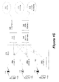
- FIG. 1A is a diagram of an example communications system 100 in which one or more disclosed embodiments may be implemented.
- the communications system 100 may be a multiple access system that provides content, such as voice, data, video, messaging, broadcast, etc., to multiple wireless users.
- the communications system 100 may enable multiple wireless users to access such content through the sharing of system resources, including wireless bandwidth.
- the communications systems 100 may employ one or more channel access methods, such as code division multiple access (CDMA), time division multiple access (TDMA), frequency division multiple access (FDMA), orthogonal FDMA (OFDMA), single-carrier FDMA (SC-FDMA), and the like.
- CDMA code division multiple access
- TDMA time division multiple access
- FDMA frequency division multiple access
- OFDMA orthogonal FDMA
- SC-FDMA single-carrier FDMA
- the communications system 100 may include wireless transmit/receive units (WTRUs) 102a, 102b, 102c, 102d, a radio access network (RAN) 104, a core network 106, a public switched telephone network (PSTN) 108, the Internet 110, and other networks 112, though it will be appreciated that the disclosed embodiments contemplate any number of WTRUs, base stations, networks, and/or network elements.
- WTRUs 102a, 102b, 102c, 102d may be any type of device configured to operate and/or communicate in a wireless environment.
- the WTRUs 102a, 102b, 102c, 102d may be configured to transmit and/or receive wireless signals and may include user equipment (UE), a mobile station, a fixed or mobile subscriber unit, a pager, a cellular telephone, a personal digital assistant (PDA), a smartphone, a laptop, a netbook, a personal computer, a wireless sensor, consumer electronics, and the like.
- UE user equipment
- PDA personal digital assistant
- smartphone a laptop
- netbook a personal computer
- a wireless sensor consumer electronics, and the like.
- the communications systems 100 may also include a base station 114a and a base station 114b.
- Each of the base stations 114a, 114b may be any type of device configured to wirelessly interface with at least one of the WTRUs 102a, 102b, 102c, 102d to facilitate access to one or more communication networks, such as the core network 106, the Internet 110, and/or the networks 112.
- the base stations 114a, 114b may be a base transceiver station (BTS), a Node-B, an eNode B, a Home Node B, a Home eNode B, a site controller, an access point (AP), a wireless router, and the like. While the base stations 114a, 114b are each depicted as a single element, it will be appreciated that the base stations 114a, 114b may include any number of interconnected base stations and/or network elements.
- the base station 114a may be part of the RAN 104, which may also include other base stations and/or network elements (not shown), such as a base station controller (BSC), a radio network controller (RNC), relay nodes, etc.
- BSC base station controller
- RNC radio network controller
- the base station 114a and/or the base station 114b may be configured to transmit and/or receive wireless signals within a particular geographic region, which may be referred to as a cell (not shown).
- the cell may further be divided into cell sectors.
- the cell associated with the base station 114a may be divided into three sectors.
- the base station 114a may include three transceivers, i.e., one for each sector of the cell.
- the base station 114a may employ multiple-input multiple output (MIMO) technology and, therefore, may utilize multiple transceivers for each sector of the cell.
- MIMO multiple-input multiple output
- the base stations 114a, 114b may communicate with one or more of the WTRUs 102a, 102b, 102c, 102d over an air interface 116, which may be any suitable wireless communication link (e.g ., radio frequency (RF), microwave, infrared (IR), ultraviolet (UV), visible light, etc. ).
- the air interface 116 may be established using any suitable radio access technology (RAT).
- RAT radio access technology
- the communications system 100 may be a multiple access system and may employ one or more channel access schemes, such as CDMA, TDMA, FDMA, OFDMA, SC-FDMA, and the like.
- the base station 114a in the RAN 104 and the WTRUs 102a, 102b, 102c may implement a radio technology such as Universal Mobile Telecommunications System (UMTS) Terrestrial Radio Access (UTRA), which may establish the air interface 116 using wideband CDMA (WCDMA).
- WCDMA may include communication protocols such as High-Speed Packet Access (HSPA) and/or Evolved HSPA (HSPA+).
- HSPA may include High-Speed Downlink Packet Access (HSDPA) and/or High-Speed Uplink Packet Access (HSUPA).
- the base station 114a and the WTRUs 102a, 102b, 102c may implement a radio technology such as Evolved UMTS Terrestrial Radio Access (E-UTRA), which may establish the air interface 116 using Long Term Evolution (LTE) and/or LTE-Advanced (LTE-A).
- E-UTRA Evolved UMTS Terrestrial Radio Access
- LTE Long Term Evolution
- LTE-A LTE-Advanced
- the base station 114a and the WTRUs 102a, 102b, 102c may implement radio technologies such as IEEE 802.16 (i.e ., Worldwide Interoperability for Microwave Access (WiMAX)), CDMA2000, CDMA2000 1X, CDMA2000 EV-DO, Interim Standard 2000 (IS-2000), Interim Standard 95 (IS-95), Interim Standard 856 (IS-856), Global System for Mobile communications (GSM), Enhanced Data rates for GSM Evolution (EDGE), GSM EDGE (GERAN), and the like.
- IEEE 802.16 i.e ., Worldwide Interoperability for Microwave Access (WiMAX)
- CDMA2000, CDMA2000 1X, CDMA2000 EV-DO Code Division Multiple Access 2000
- IS-95 Interim Standard 95
- IS-856 Interim Standard 856
- GSM Global System for Mobile communications
- GSM Global System for Mobile communications
- EDGE Enhanced Data rates for GSM Evolution
- GERAN GSM EDGERAN
- the base station 114b in FIG. 1A may be a wireless router, Home Node B, Home eNode B, or access point, for example, and may utilize any suitable RAT for facilitating wireless connectivity in a localized area, such as a place of business, a home, a vehicle, a campus, and the like.
- the base station 114b and the WTRUs 102c, 102d may implement a radio technology such as IEEE 802.11 to establish a wireless local area network (WLAN).
- the base station 114b and the WTRUs 102c, 102d may implement a radio technology such as IEEE 802.15 to establish a wireless personal area network (WPAN).
- WLAN wireless local area network
- WPAN wireless personal area network
- the base station 114b and the WTRUs 102c, 102d may utilize a cellular-based RAT (e.g ., WCDMA, CDMA2000, GSM, LTE, LTE-A, etc .) to establish a picocell or femtocell.
- a cellular-based RAT e.g ., WCDMA, CDMA2000, GSM, LTE, LTE-A, etc .
- the base station 114b may have a direct connection to the Internet 110.
- the base station 114b may not be required to access the Internet 110 via the core network 106.
- the RAN 104 may be in communication with the core network 106, which may be any type of network configured to provide voice, data, applications, and/or voice over internet protocol (VoIP) services to one or more of the WTRUs 102a, 102b, 102c, 102d.
- the core network 106 may provide call control, billing services, mobile location-based services, pre-paid calling, Internet connectivity, video distribution, etc ., and/or perform high-level security functions, such as user authentication.
- the RAN 104 and/or the core network 106 may be in direct or indirect communication with other RANs that employ the same RAT as the RAN 104 or a different RAT.
- the core network 106 may also be in communication with another RAN (not shown) employing a GSM radio technology.
- the core network 106 may also serve as a gateway for the WTRUs 102a, 102b, 102c, 102d to access the PSTN 108, the Internet 110, and/or other networks 112.
- the PSTN 108 may include circuit-switched telephone networks that provide plain old telephone service (POTS).
- POTS plain old telephone service
- the Internet 110 may include a global system of interconnected computer networks and devices that use common communication protocols, such as the transmission control protocol (TCP), user datagram protocol (UDP) and the internet protocol (IP) in the TCP/IP internet protocol suite.
- the networks 112 may include wired or wireless communications networks owned and/or operated by other service providers.
- the networks 112 may include another core network connected to one or more RANs, which may employ the same RAT as the RAN 104 or a different RAT.
- the WTRUs 102a, 102b, 102c, 102d in the communications system 100 may include multi-mode capabilities, i.e., the WTRUs 102a, 102b, 102c, 102d may include multiple transceivers for communicating with different wireless networks over different wireless links.
- the WTRU 102c shown in FIG. 1A may be configured to communicate with the base station 114a, which may employ a cellular-based radio technology, and with the base station 114b, which may employ an IEEE 802 radio technology.
- FIG. 1B is a system diagram of an example WTRU 102.
- the WTRU 102 may include a processor 118, a transceiver 120, a transmit/receive element 122, a speaker/microphone 124, a keypad 126, a display/touchpad 128, non-removable memory 130, removable memory 132, a power source 134, a global positioning system (GPS) chipset 136, and other peripherals 138.
- GPS global positioning system
- the processor 118 may be a general purpose processor, a special purpose processor, a conventional processor, a digital signal processor (DSP), a plurality of microprocessors, one or more microprocessors in association with a DSP core, a controller, a microcontroller, Application Specific Integrated Circuits (ASICs), Field Programmable Gate Array (FPGAs) circuits, any other type of integrated circuit (IC), a state machine, and the like.
- the processor 118 may perform signal coding, data processing, power control, input/output processing, and/or any other functionality that enables the WTRU 102 to operate in a wireless environment.
- the processor 118 may be coupled to the transceiver 120, which may be coupled to the transmit/receive element 122. While FIG. 1B depicts the processor 118 and the transceiver 120 as separate components, it will be appreciated that the processor 118 and the transceiver 120 may be integrated together in an electronic package or chip.
- the transmit/receive element 122 may be configured to transmit signals to, or receive signals from, a base station (e.g ., the base station 114a) over the air interface 116.
- a base station e.g ., the base station 114a
- the transmit/receive element 122 may be an antenna configured to transmit and/or receive RF signals.
- the transmit/receive element 122 may be an emitter/detector configured to transmit and/or receive IR, UV, or visible light signals, for example.
- the transmit/receive element 122 may be configured to transmit and receive both RF and light signals. It will be appreciated that the transmit/receive element 122 may be configured to transmit and/or receive any combination of wireless signals.
- the WTRU 102 may include any number of transmit/receive elements 122. More specifically, the WTRU 102 may employ MIMO technology. Thus, in one embodiment, the WTRU 102 may include two or more transmit/receive elements 122 ( e.g ., multiple antennas) for transmitting and receiving wireless signals over the air interface 116.
- the transceiver 120 may be configured to modulate the signals that are to be transmitted by the transmit/receive element 122 and to demodulate the signals that are received by the transmit/receive element 122.
- the WTRU 102 may have multi-mode capabilities.
- the transceiver 120 may include multiple transceivers for enabling the WTRU 102 to communicate via multiple RATs, such as UTRA and IEEE 802.11, for example.
- the processor 118 of the WTRU 102 may be coupled to, and may receive user input data from, the speaker/microphone 124, the keypad 126, and/or the display/touchpad 128 (e.g ., a liquid crystal display (LCD) display unit or organic light-emitting diode (OLED) display unit).
- the processor 118 may also output user data to the speaker/microphone 124, the keypad 126, and/or the display/touchpad 128.
- the processor 118 may access information from, and store data in, any type of suitable memory, such as the non-removable memory 130 and/or the removable memory 132.
- the non-removable memory 130 may include random-access memory (RAM), read-only memory (ROM), a hard disk, or any other type of memory storage device.
- the removable memory 132 may include a subscriber identity module (SIM) card, a memory stick, a secure digital (SD) memory card, and the like.
- SIM subscriber identity module
- SD secure digital
- the processor 118 may access information from, and store data in, memory that is not physically located on the WTRU 102, such as on a server or a home computer (not shown).
- the processor 118 may receive power from the power source 134, and may be configured to distribute and/or control the power to the other components in the WTRU 102.
- the power source 134 may be any suitable device for powering the WTRU 102.
- the power source 134 may include one or more dry cell batteries (e.g ., nickel-cadmium (NiCd), nickel-zinc (NiZn), nickel metal hydride (NiMH), lithium-ion (Li-ion), etc.), solar cells, fuel cells, and the like.
- the processor 118 may also be coupled to the GPS chipset 136, which may be configured to provide location information (e.g ., longitude and latitude) regarding the current location of the WTRU 102.
- location information e.g ., longitude and latitude
- the WTRU 102 may receive location information over the air interface 116 from a base station (e.g ., base stations 114a, 114b) and/or determine its location based on the timing of the signals being received from two or more nearby base stations. It will be appreciated that the WTRU 102 may acquire location information by way of any suitable location-determination method while remaining consistent with an embodiment.
- the processor 118 may further be coupled to other peripherals 138, which may include one or more software and/or hardware modules that provide additional features, functionality and/or wired or wireless connectivity.
- the peripherals 138 may include an accelerometer, an e-compass, a satellite transceiver, a digital camera (for photographs or video), a universal serial bus (USB) port, a vibration device, a television transceiver, a hands free headset, a Bluetooth® module, a frequency modulated (FM) radio unit, a digital music player, a media player, a video game player module, an Internet browser, and the like.
- the peripherals 138 may include an accelerometer, an e-compass, a satellite transceiver, a digital camera (for photographs or video), a universal serial bus (USB) port, a vibration device, a television transceiver, a hands free headset, a Bluetooth® module, a frequency modulated (FM) radio unit, a digital music player, a media player, a video game player
- FIG. 1C is a system diagram of the RAN 104 and the core network 106 according to an embodiment.
- the RAN 104 may employ an E-UTRA radio technology to communicate with the WTRUs 102a, 102b, 102c over the air interface 116.
- the RAN 104 may also be in communication with the core network 106.
- the RAN 104 may include eNode-Bs 140a, 140b, 140c, though it will be appreciated that the RAN 104 may include any number of eNode-Bs while remaining consistent with an embodiment.
- the eNode-Bs 140a, 140b, 140c may each include one or more transceivers for communicating with the WTRUs 102a, 102b, 102c over the air interface 116.
- the eNode-Bs 140a, 140b, 140c may implement MIMO technology.
- the eNode-B 140a for example, may use multiple antennas to transmit wireless signals to, and receive wireless signals from, the WTRU 102a.
- Each of the eNode-Bs 140a, 140b, 140c may be associated with a particular cell (not shown) and may be configured to handle radio resource management decisions, handover decisions, scheduling of users in the uplink and/or downlink, and the like. As shown in FIG. 1C , the eNode-Bs 140a, 140b, 140c may communicate with one another over an X2 interface.
- the core network 106 shown in FIG. 1C may include a mobility management gateway (MME) 142, a serving gateway 144, and a packet data network (PDN) gateway 146. While each of the foregoing elements are depicted as part of the core network 106, it will be appreciated that any one of these elements may be owned and/or operated by an entity other than the core network operator.
- MME mobility management gateway
- PDN packet data network
- the MME 142 may be connected to each of the eNode-Bs 142a, 142b, 142c in the RAN 104 via an S1 interface and may serve as a control node.
- the MME 142 may be responsible for authenticating users of the WTRUs 102a, 102b, 102c, bearer activation/deactivation, selecting a particular serving gateway during an initial attach of the WTRUs 102a, 102b, 102c, and the like.
- the MME 142 may also provide a control plane function for switching between the RAN 104 and other RANs (not shown) that employ other radio technologies, such as GSM or WCDMA.
- the serving gateway 144 may be connected to each of the eNode Bs 140a, 140b, 140c in the RAN 104 via the S1 interface.
- the serving gateway 144 may generally route and forward user data packets to/from the WTRUs 102a, 102b, 102c.
- the serving gateway 144 may also perform other functions, such as anchoring user planes during inter-eNode B handovers, triggering paging when downlink data is available for the WTRUs 102a, 102b, 102c, managing and storing contexts of the WTRUs 102a, 102b, 102c, and the like.
- the serving gateway 144 may also be connected to the PDN gateway 146, which may provide the WTRUs 102a, 102b, 102c with access to packet-switched networks, such as the Internet 110, to facilitate communications between the WTRUs 102a, 102b, 102c and IP-enabled devices.
- the PDN gateway 146 may provide the WTRUs 102a, 102b, 102c with access to packet-switched networks, such as the Internet 110, to facilitate communications between the WTRUs 102a, 102b, 102c and IP-enabled devices.
- the core network 106 may facilitate communications with other networks.
- the core network 106 may provide the WTRUs 102a, 102b, 102c with access to circuit-switched networks, such as the PSTN 108, to facilitate communications between the WTRUs 102a, 102b, 102c and traditional land-line communications devices.
- the core network 106 may include, or may communicate with, an IP gateway (e.g ., an IP multimedia subsystem (IMS) server) that serves as an interface between the core network 106 and the PSTN 108.
- IMS IP multimedia subsystem
- the core network 106 may provide the WTRUs 102a, 102b, 102c with access to the networks 112, which may include other wired or wireless networks that are owned and/or operated by other service providers.
- LTE Release 8 may be referred to herein as LTE R8 or R8-LTE.
- SC-FDMA Single Carrier Frequency Division Multiple Access
- DFT-S-OFDM Discrete Fourier Transform Spread Orthogonal Frequency Division Multiplexing
- a wireless transmit/receive unit may transmit on the uplink using limited, contiguous set of assigned sub-carriers in a Frequency Division Multiple Access (FDMA) arrangement, and in some embodiments perhaps only a limited, contiguous set of assigned sub-carriers in a Frequency Division Multiple Access (FDMA) arrangement.
- FDMA Frequency Division Multiple Access
- FDMA Frequency Division Multiple Access
- Orthogonal Frequency Division Multiplexing (OFDM) signal or system bandwidth in the uplink is composed of useful sub-carriers numbered 1 to 100
- a first given WTRU may be assigned to transmit on sub-carriers 1-12
- a second WTRU may be assigned to transmit on sub-carriers 13-24, and so on.
- the different WTRUs may each transmit into a subset of the available transmission bandwidth, and perhaps may each may transmit into only a subset of the available transmission bandwidth
- an evolved Node-B (eNodeB) serving the WTRUs may receive the composite uplink signal across the entire transmission bandwidth.
- eNodeB evolved Node-B
- LTE Advanced (which includes LTE Release 10 (R10) and may include future releases such as Release 11, also referred to herein as LTE-A, LTE R10, or R10-LTE) is an enhancement of the LTE standard that provides a fully-compliant 4G upgrade path for LTE and 3G networks.
- LTE-A carrier aggregation may be supported, and, unlike in LTE, multiple carriers may be assigned to the uplink, downlink, or both.
- Embodiments recognize that coordinated multi-point operation (CoMP) in the downlink may refer to a set of possible schemes wherein transmissions from multiple geographically separated transmission points may be coordinated to improve system performance in terms of cell-edge throughput and/or system throughput.
- Examples of such schemes include Joint Transmission, wherein multiple points may simultaneously transmit information intended for a WTRU; Dynamic Point Selection, wherein one of a set of points may be dynamically selected for transmission to a WTRU; and Coordinated Scheduling/Coordinated Beamforming, wherein interference towards a WTRU being scheduled from a first point may be avoided by proper coordination of interfering transmissions from a second point.
- system performance may be evaluated based on average cell throughput and/or cell-edge throughput. While average cell throughput performance can be improved by increasing the received signal strength using power boosting techniques, the cell-edge users may experience low received signal strength and the cell edge performance may therefore be primarily affected by inter-cell interference (ICI). This may be especially true for the systems designed to operate with a frequency reuse factor of one or close to one, which is contemplated by OFDM-based 4G networks.
- ICI inter-cell interference
- ICI inter-cell interference
- power boosting may not improve cell-edge performance, perhaps because both the serving cell signal and the interfering signal strengths may be increased, which may in turn increase ICI, for example.
- Embodiments contemplate other techniques that may be used to improve cell-edge performance, such as coordinated multi-point (CoMP) transmission and reception.
- CoMP coordinated multi-point
- multi-point transmission and reception embodiments transmission or reception from antennas not in "close proximity” may be implemented, where "close proximity” may be a distance beyond the spacing of a few wavelengths such that most antennas, or perhaps all antennas, may be subject to different long-term fading.
- close proximity may be a distance beyond the spacing of a few wavelengths such that most antennas, or perhaps all antennas, may be subject to different long-term fading.
- SINR Signal-to-Interference-Noise-Ratio
- PDCH Physical Downlink Control Channel
- JP embodiments joint transmission (JT) may be used, where Physical Downlink Shared Channel (PDSCH) transmissions may be sent from multiple points, such as part of a CoMP cooperating set, or perhaps an entire CoMP cooperating set, at one time.
- JP Joint processing
- PDSCH Physical Downlink Shared Channel
- Data to a single WTRU may be simultaneously transmitted from multiple transmission points, for example, to (coherently or non-coherently) improve the received signal quality and/or actively cancel interference for other WTRUs.
- dynamic cell selection may be used, where PDSCH transmissions may be sent from one point within a CoMP cooperating set at one time, for example.
- CoMP category may be coordinated scheduling/coordinated beamforming (CS/CB), where the data may be available at the serving cell (i.e ., data transmission is only performed from that point), and in some embodiments may only be available at the serving cell, but user scheduling/beamforming decisions may be made with coordination among cells corresponding to a CoMP cooperating set.
- CS/CB coordinated scheduling/coordinated beamforming
- Embodiments contemplate that at least one CoMP category may include cell aggregation. Some transmission points or each transmission point may have independent data to transmit to the WTRU on the same carrier frequency. Some cells or each cell may have its own data and/or signal flow to and from the WTRU. For example, some cells or each cell may use independent HARQ processes.
- one or more CoMP sets may include a CoMP cooperating set, where a set of geographically separated points are directly or indirectly participating in PDSCH transmission to a WTRU. This set may or may not be transparent to a WTRU.
- Another CoMP set may be CoMP transmission point(s), which may be a point or set of points that may be actively transmitting PDSCH to a WTRU.
- the set of CoMP transmission point(s) may be a subset of the CoMP cooperating set.
- CoMP transmission points may be the points in the CoMP cooperating set.
- a single point may be the transmission point in some subframes, or perhaps in every subframe. This single transmission point may change dynamically within the CoMP cooperating set.
- the CoMP transmission point may correspond to a "serving cell", for example.
- a CoMP measurement set may be the same as the CoMP cooperating set.
- Actual WTRU reports may include feedback for a subset of cells of the CoMP measurement cells, and in some embodiments may only include feedback for a subset of cells of the CoMP measurement cells, which may be referred to as reported cells.
- CSI feedback may be reported in the format of rank (e.g., rank indicator (RI)), precoder matrix index (PMI), and/or channel quality indicator (CQI), where PMI may be calculated at the WTRU by quantizing the channel against a pre-defined codebook, for example.
- CSI feedback may include CQI/PMI/RI reports and may be provided on either a periodic or an aperiodic basis. Parameters that may be used to control the information reported by the WTRU may be based on the system bandwidth and/or may be provided in radio resource control (RRC) Connection Setup, Reconfiguration, and/or Reestablishment messages.
- RRC radio resource control
- Table 1 contains a summary of exemplary reporting modes contemplated by embodiments. Table 1 - Exemplary Reporting Modes Transmission Mode Aperiodic Feedback Periodic Feedback 1: Port 0 Mode 1-0: WB CQI 2: Tx Diversity 3: Open Loop SM (large delay CDD) (or Tx Diversity) Mode 2-0: UE selected sub band CQI: WB CQI + CQI over M best subbands.
- Mode 2-0 UE Selected sub band CQI: WB CQI + UE reports CQI in preferred sub-band in each BW part, one BW part in each reporting opportunity 7: Port 5 (or port 0 or Tx Div)
- Mode 3-0 HL configured sub band CQI: WB CQI + sub-band CQI.
- 8 (without PMI): Port 7/8 (or single port or Tx Div): Release 9 only Note - CQI for first CW only, No PMI Note - CQI for first CW only, No PMI 4: Closed Loop SM (or Tx Div) Mode 1-2: WB CQI / Multiple PMI: CQI for each CW; PMI for each sub-band.
- Mode 1-1 WB CQI / Single PMI 6: Closed Loop Rank 1 Precoding (or Tx Div)
- Mode 2-2 UE selected sub band CQI / Multiple PMI: CQI per CW and PMI, both over full BW and M best subbands.
- Mode 2-1 UE selected sub-band CQI / Single PMI (N DL RB > 7 only): WB CQI/PMI + UE reports CQI in preferred sub-band in each BW part 8 (with PMI): Port 7/8 (or single port or Tx Div): Release 9 only
- Mode 3-1 HL configured sub band CQI / Single PMI: WB CQI + sub-band CQI, both per CW.
- 5 MU-MIMO (or Tx Div)
- Mode 3-1 HL configured sub band CQI / Single PMI (see above)
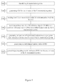
- Periodic reporting may use a sequence of one or more different types of reports. Such types may include "Type 1" that may report sub-band CQI, "Type 2" that may report wideband CQI/PMI, "Type 3" that may report RI, and "Type 4" that may report wideband CQI, for example.
- An exemplary reporting sequence is illustrated in Figure 2 , where the number in each rectangle corresponds to the report type described above.
- aperiodic feedback may be requested by Format 0 downlink control information (DCI) or a random access response (RAR) when a CQI Request bit is set.
- DCI downlink control information
- RAR random access response
- aperiodic feedback may be transmitted on the PUSCH channel.
- Such types of periodic PUCCH feedback may include a "Type 1" report that may support CQI feedback for WTRU selected sub-bands, a "Type 1a” report that may support sub-band CQI and second PMI feedback, a "Type 2", “Type 2b", and “Type 2c” report that may support wideband CQI and PMI feedback, a "Type 2a” report that may support wideband PMI feedback, a "Type 3” report that may support RI feedback, a "Type 4" report that may support wideband CQI, a "Type 5" report that may support RI and wideband PMI feedback, and a "Type 6" report that supports RI and PTI feedback.
- CSI feedback such as that used in LTE R8 and R10 for example, may be designed to support single-cell operation and Physical Downlink Shared Channel (PDSCH) scheduling.
- PDSCH Physical Downlink Shared Channel
- the CSI feedback may represent the channel between itself and the serving cell and may be reported to the serving cell, and in some embodiments perhaps only to the serving cell.
- Embodiments contemplate that or more WTRU feedback procedures may be intended for single cell downlink operation.
- a WTRU may be required to provide multiple feedbacks containing CSI information of different CoMP cells or transmission points needed for various functions such as CoMP set determination, CoMP activation/deactivation, and/or downlink scheduling/beamforming.
- Several feedback configuration embodiments for CoMP implementations are contemplated.
- One or more embodiments contemplate addressing both aspects of content and the rate of the feedback mechanisms.
- Embodiments recognize that some feedback procedures defined up to R10 may be optimized for the case where some or all transmission points (or antenna ports) of the cell may be geographically close to each other.
- a set of geographically separated RRHs may utilize the same physical cell identity.
- using the WTRU to report CSI of some or all deployed antenna ports of a same cell using R10 methods may be inefficient because the channel quality for some antenna ports is likely to be much weaker than for other antenna ports.
- the signals transmitted from different RRHs may have different characteristics which need to be taken into account by the WTRU in the evaluation of CSI.
- Embodiments recognize that CSI may be evaluated and reported assuming that reference signals are transmitted from a set of closely separated antennas from a same physical transmission point, and which therefore may share the same long-term path loss between them and the WTRU. Where this assumption may not be satisfied, the CSI may not be useful (or optimum) to the network for scheduling purposes. For instance, the network may not be able to determine which transmission point or set of transmission points may be the most appropriate for scheduling the UE in a particular instance.
- Embodiments also recognize that the set of transmission points that may be appropriate for CoMP operation may be dependent on the location of the WTRU in the cell.
- Embodiments contemplate one or more techniques for determining appropriate set(s) of transmission points, and/or the associated sets of reference signals (e.g., CSI-RS) which may be configured for the WTRU, for example.
- CSI-RS reference signals
- transmission point may refer to any antenna port or subset of geographically co-located antenna ports from the network that may be transmitting to, or receiving from the WTRU.
- the set of transmission points configured or activated for a given WTRU may or may not belong to the same physical cell identity.
- a transmission point may transmit one CSI-RS or one set of CSI-RS.
- CSI-RS-resource or “non-zero-power CSI-RS-resource” may refer to a set of CSI-RS reference signals and/or antenna ports that may be transmitted from one transmission point or one set of transmission points.
- characteristics of these reference signals may be provided to the WTRU by higher layers, such as RRC signaling, for example.
- a WTRU may be configured with one or multiple CSI-RS resources for the purpose of CSI evaluation and reporting.
- the phrase "transmission point" may be used alternatively with the phrase "CSI-RS resource" where, in one or more embodiments, the CSI-RS-resource may correspond to the transmission point.
- a transmission point may also transmit at least one common reference signal (CRS) and a WTRU may also measure the at least one CRS for the purpose of CSI evaluation and/or reporting, among other purposes, for example.
- CRS common reference signal
- a CSI-RS-resource may be a set of CSI-RS reference signals or antenna ports that may be transmitted from one transmission (or possibly multiple transmission points). The characteristics of these reference signals may be provided to the WTRU by higher layers.
- the WTRU may be configured with one or multiple CSI-RS resources for the purpose of CSI evaluation and/or reporting, for example.
- transmission point may be substituted by "CSI-RS-resource” where it may be understood that the CSI-RS-resource may correspond to the transmission point.
- a Per-point rank indication may correspond to a recommended number of useful transmission layers (or rank) for a transmission from one transmission point.
- the per-point RI may equivalently be referred to as "per-CSI-RS-resource RI" perhaps if the concerned CSI-RS-resource may be used for the CSI measurement, or "per-CRS" or “per-cell” RI perhaps if CRS may be used for the CSI measurement.
- per-point CQI may correspond to a channel quality indicator (CQI) that may be applicable to the transmission of a codeword (or PDSCH transport block) from one transmission point.
- CQI channel quality indicator
- the per-point CQI may equivalently be referred to as "per-CSI-RS-resource CQI" perhaps if the concerned CSI-RS-resource may be used for the CSI measurement, or "per-CRS” or “per-cell” CQI perhaps if a common reference signal (CRS) may be used for the CSI measurement.
- a per-point pre-coding matrix indicator or a local precoding matrix indicator may correspond to a recommended precoding matrix (or precoder) for a transmission from one transmission point.
- the per-point PMI may equivalently be referred to as "per-CSI-RS-resource PMI” perhaps if the concerned CSI-RS-resource may be used for the CSI measurement, or "per-CRS" or "per-cell” PMI perhaps if CRS may be used for the CSI measurement.
- there may be more than one pre-coding matrix indicator jointly indicating a single pre-coding matrix e.g. a first pre-coding indicator and a second pre-coding indicator, where the latter may vary more rapidly than the former in time).
- joint rank indication or common rank indication may correspond to a recommended number of useful transmission layers for a joint transmission from more than one transmission point, which may be corresponding to more than one CSI-RS-resource, for example.
- Aggregated CQI or Joint CQI may correspond to a CQI that may be applicable to a joint transmission of a codeword from more than one transmission point, which may be corresponding to more than one CSI-RS-resource.
- the aggregated CQI may be estimated assuming a certain pre-coding vector or matrix is used at some or each transmission point corresponding to a CSI-RS resource.
- the aggregated CQI may also be estimated assuming a certain relationship between the precoders used in the transmission points corresponding to these CSI-RS-resources. For instance, it may be assumed that the relative phase between the pre-coders is such that the signals from the transmission points combine coherently (with a zero phase difference) or combine with a pre-determined phase difference, among other contemplated assumptions.
- aggregated PMI or global PMI may correspond to a recommended precoding matrix for a transmission from more than one transmission point, which may be corresponding to more than one CSI-RS-resource.
- the dimensions of the recommended pre-coding matrix may correspond to the total number of antenna ports from the at least one CSI-RS-resource, times the number of layers (or rank), for example.
- inter-point phase indicator or combining indicator may correspond to a recommended inter-point phase difference for at least one transmission layer, for at least one pair of precoding matrices that may be used in transmission points.
- the inter-point phase indicator may equivalently be referred to as "inter-CSI-RS-resource indicator” perhaps if the concerned set of CSI-RS-resources may be used for the CSI measurement, or "inter-CRS” or “inter-cell” CQI perhaps if a common reference signal (CRS) may be used for the CSI measurement.
- the term "CSI of a set of transmission points" may refer to any type of channel state information derived from any subset of this set of transmission points. For example, it may include channel quality information, rank indication, precoding matrix indications, and/or any type of explicit or implicit feedback. It may also include a type of channel state information, heretofore undefined, that is a function of more than one transmission point, as disclosed herein.
- Embodiments contemplate devices and techniques, which can be used individually or in combination, to efficiently evaluate and/or report CSI pertaining to transmission points that may be geographically separated.
- the WTRU may report the CSI of different transmission points (or CSI-RS-resources), or subsets thereof, that are configured for CSI reporting in different subframes.
- the subsets of transmission points may be determined based on one or more of: receiving the transmission points (or corresponding reference signals such as CSI-RS) that are part of each subset from higher layers (e.g., RRC signalling or MAC signalling); and/or one or more characteristics of signals received from the transmission points.
- a characteristic of a signal may include, but is not limited to: the CSI-RS (channel state indicator reference signal) transmitted from each Tx point; the CRS (common reference signal) transmitted from each point; the physical cell identity used to derive a reference signal transmitted from each point (e.g., a subset of transmission points may be defined to correspond to all transmission points from a specific cell; and a quality metric (such as received signal strength, received signal quality, and/or channel quality information) of a signal received from each transmission point.
- the CSI-RS channel state indicator reference signal
- CRS common reference signal
- two subsets of transmission points may be defined, where one may correspond to transmission points received at a relatively high power level (an "active" subset - for example) for which accurate and timely CSI information may be required, and the other may correspond to transmission points received at a relatively low level (a "monitored" subset -for example) for which CSI information may not be required, at least not very frequently.
- the network could determine which transmission points is/are part of each subset and indicate the active and monitored subsets of Tx points using radio resource control signalling.
- the WTRU could determine whether a transmission point may belong to the active or the monitored group by determining whether the received signal strength is above or below a threshold (and in some embodiments, perhaps above or below a threshold for a predefined period of time) which could be signalled by the network through higher layers, and/or be function of the received signal strength of the best transmission point, for example.
- the configuration of the active set can be done, for example, by providing a set of non-zero-power CSI-RS-resources and/or, in some embodiments, a set of cell identities to the WTRU.
- a first subset of transmission points may be defined as the set of transmission points used by the serving cell of the WTRU, while other subsets of transmission points (“non-serving" subsets - for example) may be defined according to the cells from which they are transmitted.
- one subset may contain a single specific transmission point identified as a "serving" transmission point, while at least one other subset may contain at least one transmission point identified as "assisting" transmission point.
- the subframes for which the WTRU reports CSI of a specific subset of transmission points may be determined by a specific function of the system frame number and subframe number.
- the function may be defined such that subframes for which at least a portion of the CSI of a specific subset of transmission points is reported may occur periodically.
- different portions of the CSI for the same transmission point e.g. the RI and the PMI/CQI
- the periodicity (and/or offset) may be different for different subsets of transmission points or different types or portions of the CSI. This could allow, for example, the WTRU to send CSI more frequently for a first subset of transmission points (the "active" subset or the "serving” subset) than for a second subset of transmission points (the "monitored" subset or the "non-serving” subset).
- the parameters of the specific function determining in which subframes a specific subset are reported may be provided by higher layers (e.g. RRC signaling). For instance, higher layers may provide the periodicity and offset for each subset of transmission points and/or portions of CSI, perhaps through a single index from which these parameters can be derived.
- the periodicity of a second subset may be determined as a pre-determined or signaled multiple of the periodicity of a first subset. Also by way of example, one or more embodiments contemplate that for certain subsets there may be no periodic reporting at all.
- CSI may be reported if an aperiodic CQI/CSI request is received by the WTRU, and in some embodiments perhaps may only be reported if an aperiodic CQI/CSI request is received by the WTRU.
- the CSI feedback of a first set of transmission points can be configured for PUSCH reporting mode 2-2 (where sub-band PMI and CQI may be reported) while CSI feedback of a second subset of transmission points can be configured for PUSCH reporting mode 1-2 (where wideband CQI and sub-band PMI may be reported) or PUSCH reporting mode 3-1 (where wideband PMI and sub-band CQI may be reported).
- the WTRU may also report CSI of a specific subset in a given subframe (n) if it received an aperiodic CSI request in a previous subframe (n-k) where k may be pre-defined or signaled.
- aperiodic CSI request may, for example, be signaled at the physical layer by setting a specific field of downlink control information (DCI) to at least one of a subset of values, where the DCI may be signaling an uplink grant and may be transmitted over a PDCCH or another downlink control channel, such as an enhanced control channel (E-PDCCH).
- DCI downlink control information
- E-PDCCH enhanced control channel
- the subset (or set of subsets) for which the WTRU may report CSI may be determined and/or derived according to one or more of: (1) a characteristic of the downlink transmission containing the aperiodic CSI request; (2) the timing of the subframe where the request is received (n-k) or of the subframe where the CSI is to be reported (n), possibly expressed in terms of a system frame number and subframe number; (3) the set of CSI-RS that are received (transmitted) in the same subframe as the aperiodic CSI request, or the set of CSI-RS that are received or transmitted in x - y subframe as the aperiodic CSI request, where x is the subframe in which the aperiodic CSI request is received and y is a predetermined, or configured value; (4) the set of CSI-RS that are received (transmitted) in the same subframe as the aperiodic CSI request, or the set of CSI-RS that are received or transmitted in x - y
- a characteristic of the downlink transmission containing the aperiodic CSI request may include, but is not limited to: (1) an indication from the downlink control signaling (such as PDCCH) containing the aperiodic CSI request for the UE (e.g., the indication may be provided by specific codepoint(s) of an existing field, such as the CQI request field, or possibly of a field in a heretofore undefined DCI format); (2) the transmission point(s) used for the transmission of the downlink control signaling (such as an evolved PDCCH for example) containing the aperiodic CSI request (e.g., in case downlink control signaling is conveyed through an enhanced control channel, the subset of transmission points for which the WTRU reports CSI could correspond to the set of transmission points used in the transmission of the enhanced control channel; (3) the cell from which the downlink control signaling containing the aperiodic CSI request is transmitted (e.g., the WTRU may report the CSI of the subset of
- the WTRU may report, in a given subframe, the CSI for a subset of transmission points determined according to one or more of: (1) determining a maximum number M of transmission points or subsets of transmission points and/or subset of CSI-RS-resources for which to report CSI. This value may be pre-determined or signaled by higher layers; and/or (2) selecting up to M transmission points or subset thereof, for which the value(s) of an associated metric are the largest values among all transmission points (or subset thereof) configured for CSI reporting, and/or which may be above a certain threshold.
- the associated metric may be representative of the quality of a signal received from the corresponding transmission point(s) and/or the expected performance of a transmission over these transmission points. In one or more embodiments, the metric may be associated to each transmission point or each subset of transmission points.
- Embodiments also contemplate that a single metric may be associated to the selection of M transmission points.
- the selection of transmission points may be based on one or more of: (1) the wideband CQI from the transmission point, or the best possible wideband CQI over precoding matrices for the subset of transmission points; (2) the sub-band CQI if the report is for a particular sub-band, or the maximum of the sub-band CQI over subbands, using the best precoding matrix (for a subset of transmission points); (3) the received signal strength (RSRP) from the transmission point(s); (4) the received signal quality (RSRQ) from the transmission point(s); (5) the expected throughput for a hypothetical transmission from the selected transmission points; and/or (6) the maximum rank for a hypothetical transmission from the selected transmission points, wherein the same or different layer(s) and/or flow(s) may be received from some transmission points or each transmission point.
- RSRP received signal strength
- RSRQ received signal quality
- the WTRU may choose to select up to M transmission points according to one or more of: (1) selecting the transmission point that provides the best channel quality as measured by, for example CQI, RSRP, and/or RSRQ, etc. or the like, possibly assuming at least one precoding matrix; and (2) adding another transmission point to the reported set of transmission points if the performance metric (such as throughput or SINR etc.) is improved by no less than a pre-defined threshold, and in some embodiments perhaps only if the performance metric (such as throughput or SINR etc.) is improved by no less than a pre-defined threshold.
- the metric associated to the selection of M transmission points as described herein may persist for a predefined period of time. For example, if the metric relies on the CQI report, a transmission point may be selected if the measured quantity is above/below a threshold for a period of time.
- an activation state may be defined for transmission point(s) or subset(s) thereof.
- the WTRU may report the CSI for transmission point(s) and/or subset(s) thereof, which are in the "active" state.
- the WTRU may not measure quality of reference signal(s) associated to non-active transmission point(s) or subset(s) thereof.
- the activation state may be determined using one or more of: (1) setting the initial activation state following configuration of transmission point(s) or subset(s) thereof to either "active" or "non-active”; and/or (2) explicit activation or de-activation through reception an activation or de-activation command.
- the command may be conveyed by, for example, physical layer signaling such as from the reception of a PDCCH control signaling (e.g., a DCI) with one or more of the following characteristics: the DCI is scrambled using a Radio-Network Identifier (RNTI) which may indicate the use of at least one CoMP function; the DCI indicates at least one radio resource assignment (e.g. a downlink assignment) such that said assignment indicates that CoMP is applicable for the transmission; and/or any of the above characteristic where said signaling may include an indication (e.g. a bit) for activation and/or deactivation of at least one CoMP function.
- RNTI Radio-Network Identifier
- the command may be conveyed by one or both of MAC layer signaling (e.g.
- a metric associated to the transmission point, or subset thereof falls below a threshold
- the WTRU reports one or more measurements that may trigger the network to start utilizing the transmission point, or subset thereof, for transmission to the WTRU
- a timer that was started (or re-started) at the last transmission from the network utilizing the transmission point(s), or subset thereof, expires.
- the WTRU may transmit a HARQ A/N to acknowledge the activation/deactivation of the CoMP function.
- the signaling procedure may be built based on an index table, (e.g. 00, 01, 10, 11) to a configuration of the CSI reporting/mode and/or reporting CoMP Set, and/or feedback format, and/or feedback resource to use, for example.
- Embodiments contemplate techniques that may be used to indicate a set of transmission points in the uplink for the purpose of CSI reporting or measurement reporting, and/or in downlink control signaling (such as a DCI format of a PDCCH or enhanced PDCCH) for the purpose of aperiodic CSI request or data transmission.
- the WTRU may indicate (or may have indicated to it) the transmission point(s) or subset(s) of transmission points by a bitmap where each bit position may correspond to a specific transmission point or subset thereof.
- the subset of transmission point(s) may implicitly be indicated by a characteristic of transmission of the concerned signaling, such as, the timing of the subframe of the transmission of the concerned signaling (CQI report, DCI, etc.), and the transmission points used for the transmission of the concerned signaling.
- a pre-defined sequence of bits may be used to replace the CSI of transmissions points for which CSI is not reported.
- an index may be associated with some or each CSI-RS-resource in the configuration. The WTRU may report this index together with the associated CSI report. The index may be explicitly provided or implicitly determined in the WTRU according to the order of the received configurations in the RRC message, for example.
- Embodiments contemplate components of the CSI feedback of a set of K transmission points.
- the measurements that may be used as a basis for the determination of CSI feedback may be derived from at least one of a set of following signals: CSI-RS reference signals; CRS reference signals; and/or other types of reference signals.
- Such reference signals may be transmitted on a number A k of (reference signal) antenna ports for the kth transmission point of the set.
- the configuration of antenna ports for some or each transmission point, as well as one or more mapping techniques for the associated reference signals, are contemplated by embodiments.
- the WTRU may report a "Joint Rank indication" RI joint or “Common rank indication” that may be achieved for a joint transmission over some or all K transmission points of the set.
- the Joint Rank Indication may be interpreted, for example, as the recommended number of useful transmission layers (or rank) for joint transmission over the K transmission points.
- the WTRU may report a per-point rank indication RI k which may correspond to the recommended number of useful transmission layers (or rank) for transmission over the k th transmission point, and in some embodiments perhaps over the k th transmission point only.
- the per-point rank indication may also be referred to as "per-CSI-RS-resource rank indication" in case a CSI evaluation is based on CSI-RS measurement, for example.
- per-point rank indication may include unconditioned per-point rank indication and/or conditioned per-point rank indication.
- Unconditioned per-point rank indication RI k may indicate a transmission to the WTRU (and in some embodiments perhaps to the WTRU only) over transmission point k, without any assumption on the precoding utilized on other transmission points for other WTRU(s).
- Conditioned per-point rank indication RI k may indicate a transmission to the WTRU (and in some embodiments perhaps to the WTRU only) over transmission point k, assuming that transmission to other WTRU's takes place on other transmission points with one or more precoders.
- the one or more precoder(s) may be indicated by the WTRU for the other transmission points, whose use may result in maximum interference to the WTRU. Alternatively or additionally, in one or more embodiments, the one or more precoder(s) may be indicated by the WTRU for the other transmission points, whose use may result in minimum interference to the WTRU.
- the one or more precoder(s) may include a "zero" precoder (e.g., no transmission or "muting"). Precoders from the subset of precoders may be indicated by the WTRU for the other transmission points, such as from a set of allowed precoders, or from outside a set of restricted precoders.
- the use of such precoders may allow the WTRU to properly receive data from relevant transmission points.
- the WTRU may receive data from relevant transmission points independently.
- the rank indication(s) may be reported for the whole frequency band or for a specific set of sub-bands, for example.
- a WTRU may report at least one channel quality index (CQI) corresponding to at least one combination of transmission parameters (e.g., modulation, code rate, transport block size).
- CQI channel quality index
- this combination may be such that a single PDSCH transport block (e.g., codeword) occupying a certain CSI reference resource can be received with a transport block error probability not exceeding a pre-determined threshold (such as 0.1, for example).
- a pre-determined threshold such as 0.1, for example.
- Different types of CQI may be defined based on the assumed type of transmission over the K transmission points, as described herein.
- CQI may include several types, such as “joint CQI” or “aggregated CQI” (CQI joint ) and “per-point CQI” or “per-CSI-RS-resource CQI” (CQI k ).
- Joint (or aggregated) CQI may include the CQI for a joint transmission of a codeword over all K transmission points of the set.
- a point may be in one of the following states: transmitting to the WTRU, interfering to the WTRU (e.g ., transmitting to another WTRU), muted ( e.g ., blanked), or unknown.
- Unknown state(s) may indicate that the WTRU makes no assumption on the transmission state of the point, and the point may be in one of the three aforementioned defined states.
- the points that are assumed to be transmitting to the WTRU may transmit coherently or non-coherently.
- the WTRU may feedback coherent joint (or aggregated) CQI and non-coherent joint (or aggregated) CQI, based on the assumption made on the transmitting points.
- Joint (or aggregated) CQI may include coherent joint CQI and non-coherent joint CQI.
- Coherent joint (or aggregated) CQI may assume that symbols of a codeword may be transmitted over up to K transmission points using a determined relationship between the precoders used in each K transmission points, possibly according to a combining matrix or combining indicator, described herein. For instance, it may be assumed that the relative phase between the pre-coders is such that the signals from the transmission points combine coherently (with a zero phase difference) or combine with a pre-determined phase difference.
- Non-coherent joint (or aggregated) CQI may assume that symbols of a codeword may be transmitted over up to K transmission points, without a determined relationship between the precoders used in some or each K transmission points.
- Embodiments contemplate evaluating CQI for a transmission from more than one transmission point, for example.
- a WTRU may estimate the received signal strength S RS,i of at least one resource element in which it is known that a CSI-RS or CRS signal is present according to the WTRU configuration.
- a ratio P c,i may be determined between the energy per resource element (EPRE) of this reference signal (CSI-RS or CRS) and the EPRE of the PDSCH transmission for the at least one resource element.
- the interference I may be estimated by measuring energy from other resource elements provided by the network, among other techniques, for example.
- Per-point CQI or per-CSI-RS-resource CQI may include the CQI for a transmission of a codeword to this WTRU over the k th transmission point, and in some embodiments perhaps only over the k th transmission point.
- Per-point CQI may include unconditioned per-point CQI k and conditioned per-point CQI k .
- Unconditioned per-point CQI k may indicate CQI for a transmission of a codeword to this WTRU over transmission point k (and perhaps only over transmission point k), without any assumption on the precoding utilized on other transmission points for other WTRU's, or for independent data to the WTRU.
- Conditioned per-point CQI k may indicate CQI for a transmission of a codeword to this WTRU over transmission point k (and perhaps only over transmission point k), assuming that transmission to other WTRU's takes place on other transmission points with one or more precoder(s).
- the precoder(s) may be indicated by the WTRU for the other transmission points, which use may result in maximum interference to the WTRU.
- the precoder(s) may be indicated by the WTRU for the other transmission points, which may result in minimum interference to the WTRU.
- the precoder(s) may include a "zero" precoder (e.g., no transmission or "muting").
- Precoders from the subset of precoders may be indicated by the WTRU for the other transmission points, such as from a set of allowed precoders, or from outside a set of restricted precoders, for example.
- the use of such precoders may allow the WTRU to properly receive data from relevant transmission points.
- the CQI may be reported for the whole frequency band or for a specific set of subbands, for example.
- the WTRU may report, for a first type/sub-type of CQI applicable to a first codeword, the difference between the value of this first type/sub-type of CQI and the value of a second type/sub-type of CQI applicable to the same codeword or a second codeword.
- the second type/sub-type of CQI for a codeword may be encoded differentially with respect to the respective first type/sub-type of CQI.
- a WTRU may report at least one precoding matrix indicator (PMI) applicable to a set of K transmission points.
- PMI may include global precoding matrix indicator, local precoding matrix indicator, and interference precoding matrix indicator.
- At least one global precoding matrix indicator may correspond to a global (or "aggregated") precoding matrix W of dimension (A 1 +A 2 +...A K ) x RI joint .
- This matrix may represent a recommended precoder for the transmission of data for this WTRU over some or each of RI joint layers from some or all K transmission points.
- the interpretation of the global (or aggregated) PMI may depend on the last reported joint rank indication RI joint .
- a local (or "per-point” or “per-CSI-RS-resource") precoding matrix indicator for a transmission point k may include a matrix W k of dimension A k x RI k . This matrix may represent a recommended precoder for the transmission of data for this WTRU over each of RI k layers from the k th transmission point.
- the interpretation of the local (or per-point) PMI may depend on the last reported per-point rank indicator RI k .
- a precoding matrix indicator for a transmission point k may include a matrix Y k .
- This matrix represents a precoder that may be used for transmission of undesired data, such as data transmitted for another WTRU from the k th transmission point.
- This precoder may correspond to at least one of a precoder for transmission to at least one other WTRU, which may result in minimum interference to the WTRU for at least one transmission layer. It may also correspond to a precoder for transmission to at least one other WTRU, which may result in maximum interference to the WTRU for at least one transmission layer.
- a set of precoding matrices W k ⁇ for one or more transmission points k 1 may correspond to a set of precoders.
- the set of precoding matrices may include groups of precoder matrices.
- the set may correspond to a set of precoder(s) that may not be used by the transmission point k 1 to ensure the WTRU may correctly receive, possibly independent, data from other transmission point(s) (e.g., k 2 ).
- the set may correspond to a set of precoder(s) from which the transmission point k 1 may select a precoder in the event the transmission point k1 chooses to not use the precoder identified by the precoder matrix indication fed back by the WTRU.
- the at least one precoding matrix indicator corresponding to a local (or per-point) precoding matrix W k may include one or more of:
- embodiments contemplate: one indication for each transmission point of a quantized timing offset ⁇ for at least one transmission layer, where the reference may be the timing of one specific transmission point; one indication for each transmission point (i k,comb ) of the phase difference (or correction) that should be applied, for each transmission layer, to the precoders of this transmission point for coherent combining; and/or two indications for each transmission point (i 1k,comb and i 2k,comb ) of the phase difference (or correction) that may be applied, for each transmission layer, to the precoders of this transmission point for coherent combining, where
- one or more precoding matrix indicators corresponding to the global (or aggregated) precoding matrix W may also include the following:
- a global (or aggregated) precoding matrix W may include a single index i 1 (and perhaps a single index i 1 ) that may correspond to a property of the global precoding matrix, which may not change on a short-term basis.
- index i 1 may correspond to a set of weights and/or beams that may be applied to the transmission points.
- the global (or aggregated) precoding matrix W may include an index i 2k for each transmission point k.
- Index i 2k may correspond to a property of each local (or per-point) precoding matrix that may change on a short-term basis.
- index i 2k may correspond to the selected subset of weights and the co-phasing between each polarization for each of the RI transmission layers.
- a WTRU may receive one layer from two transmission points, each with 4 x-pol transmit antennas
- the four ports assigned to transmission point 'a' may be represented as a 1 ,a 2 ,a 3 ,a 4 , and the four ports of transmission point 'b' may be represented as b 1 ,b 2 ,b 3 ,b 4 .
- the precoding matrix may be mapped to the antenna ports as follows: W ⁇ [ a 1 , a 2 , b 1 , b 2 , a 3 , a 4 , b 3 , b 4 ] T .
- the same long-term/wideband PMI i 1 may be used by both transmission points.
- Each transmission point may have its own short-term/narrowband i 2 (such as i 2a and i 2b ).
- Index i 1 may require 4 bits of feedback, while index i 2a may require 4 bits and index i 2b may require 2 bits.
- precoding at transmission point a may require i 1 and i 2a .
- Precoding at transmission point b may require i 1 , i 2a and i 2b .
- An alternative transmission point b may, for example, only have feedback i 1 and i 2b .
- the codebooks at each transmission point may include (see Tables 3 and 4): Table 3 - Exemplary Codebook for 1-layer CSI reporting at transmission point a.
- the set of precoding matrices W k ⁇ may include an index (and perhaps a single index) that may correspond to a group of precoding matrices according to a predetermined mapping.
- the interpretation of the group of precoding matrices may depend on the last reported per-point rank indication RI k and/or the precoding matrix indicator that corresponds to the desired precoding matrix to be used for this WTRU.
- the set of precoding matrices may include multiple indices, each indicating specific precoding matrices according to a predetermined mapping whose grouping constitutes the set, for example.
- a WTRU may report at least one power adjustment indicator PAI k for at least one transmission point.
- the power adjustment indicator PAI k may maps to a value of a recommended power adjustment for at least one of the DM-RS reference signal and the data symbols for a transmission to this WTRU from transmission point k. This may allow the network to better balance received power from all transmission points.
- the mapping between the power adjustment indicator and the actual power adjustment (e.g. in dB) may be pre-defined or provided by higher layers, for example.
- the WTRU may report channel state information assuming a certain type of single-point or multi-point transmission from the network. Such transmission hypotheses can be referred to as a "transmission state" herein.
- the transmission state may include, for at least one transmission point, an assumption about whether this transmission point is:
- the transmission point may be in a transmission state such as (T)ransmitting, (I)nterfering (e.g. undesired transmission, for example, to another WTRU), (B)lanked and/or (U)nknown.
- TSV Transmission State Vector
- Some or each Transmission State Vector may be indicated by one or more Transmission State Indicator (TSI).
- TSI Transmission State Indicator
- the TSI may be a scalar value that may map to the TSV or may be the TSV itself. Additionally or alternatively, the TSI may be a bitmap representing the TSV.
- the WTRU may feedback with assumptions on five points that may include two transmitting points, two interfering points and one blanked/muted point.
- An exemplary corresponding TSI may include a vector such as [T T I I B].
- the exemplary corresponding TSI may include a value that may map to a vector such as [T T I I B].
- Additional transmission states or TSI may be defined to indicate whether a joint transmission is assumed to be coherent (i.e. use combining indicator or inter-point phase information) or non-coherent.
- a WTRU may be configured to report CSI for certain possible transmission states, and in some embodiments perhaps for only certain possible transmission states.
- the WTRU may be configured to report CSI for 2 points and may be configured to report CSI for the following transmission states:
- Embodiments contemplate that transmission state selection may be controlled by the network.
- the network may determine the transmission state or TSI value(s) (e.g. TSI value(s) corresponding to a CSI report).
- the network may indicate a TSI and/or TSV for the WTRU to use via higher layer signaling.
- the network may indicate a TSI and/or TSV for the WTRU to use for periodic or aperiodic feedback grant, for example.
- the TSI may be used for one instance of aperiodic feedback, or may be used for the duration of a semi-persistent aperiodic feedback grant.
- the TSI may be associated with one or more subframe number(s).
- the association may be preconfigured by higher layer signaling.
- the TSI and/or TSV may be based on a previous feedback.
- the WTRU may feedback an indicator that may indicate to the network that the TSI and/or TSV has changed.
- the new TSI and/or TSV may cycle to another preconfigured value.
- the WTRU may feedback an indicator that may indicate to the network that the TSI and/or TSV should be changed.
- the network may be prompted to indicate the new TSI and/or TSV to the WTRU before another CSI feedback is performed by the WTRU.
- TSI/TSV selection may be controlled by the WTRU.
- the WTRU may feedback the TSI and/or TSV to inform the network of the conditions with which the CSI feedbacks have been calculated.
- the WTRU may determine the TSI and/or TSV value(s). For example, for n points, the WTRU may select from the 4 n possible TSI and/or TSV values. For example, the WTRU may select from a subset of possible TSI and/or TSV values. The subset of possible TSI and/or TSV values may be signaled to the WTRU.
- the subset may be signaled to the WTRU by one or more methods described above with respect to network-controlled TSI and/or TSV selection (e.g ., by replacing TSI with TSI set).
- the subset of possible values may include the TSVs with a single point (T)ransmitting. In some embodiments, no other condition on other points may be used ( e.g ., DPS without muting).
- the subset of possible values may include the TSIs with at least two points (T)ransmitting and other points (B)lanked ( e.g ., joint-transmission with blanking).
- the WTRU may feedback an indicator to the network indicating that the selected TSI and/or TSV has changed.
- the new TSI and/or TSV may be pre-configured, or may be fed back by the WTRU, for example.
- the WTRU may select TSI(s) and/or TSV(s) from a set of possible transmission states or a set of possible values (e.g. including in an embodiment a subset of the possible 4 n values, where n is the number of points).
- the TSI and/or TSV may be selected based on the number of points required to achieve a pre-configured threshold on performance.
- the WTRU may select the TSI(s) and/or TSV(s) that may require the fewest (or most) points to transmit to achieve a pre-configured threshold on performance (for example, maximizing the SINR, minimizing the BLER, maximizing the throughput, or the like).
- the TSI(s) and/or TSV(s) may be selected based on the number of points that may need to be blanked to achieve a pre-configured threshold on performance. For example, the WTRU may select the TSI(s) and/or TSV(s) that may require the fewest (or most) points to be blanked to achieve a pre-configured threshold on performance (for example, maximizing the SINR, minimizing the BLER, maximizing the throughput, or the like). The TSI(s) and/or TSV(s) may be selected based on the restrictions on non-transmitting points.
- the WTRU may select the TSI(s) and/or TSV(s) that may impose the fewest (or most) restrictions on non-transmitting points (the fewest (or most) unknown points) to achieve a pre-configured threshold on performance (for example, maximizing the SINR, minimizing the BLER, maximizing the throughput, or the like).
- the TSI(s) and/or TSV(s) may be selected based on CQI and/or rank (e.g. (RI)).
- the WTRU may select the TSI(s) and/or TSV(s) that may have the highest CQI and/or the highest rank (e.g. (RI)).
- the TSI(s) and/or TSV(s) may be selected based on throughput or an amount of bits that may be transferred. For example, the WTRU may select the TSI(s) and/or TSV(s) that may maximize the total throughput or the total amount of bit that may be transferred in a subframe if the network followed a recommended CSI (e.g. including both CQI and RI). In one or more embodiments, the WTRU may select a TSI and/or TSV from the allowed TSI and/or TSV subset.
- the allowed TSI and/or TSV subset may include TSIs and/or TSV(s) that correspond to points that are in the (T)ransmitting state and satisfy one or more of the following criteria: surpass a minimal allowable path loss threshold, achieve a minimal per-point CQI threshold, and/or surpass a certain per-point CQI differential threshold when compared to the maximum per-point CQI threshold.
- the WTRU may use one or more parameters including parameters that may be related, corresponding, or specific to the transmission state (as described previously) and/or the type of reported CSI (e.g. whether the CSI feedback may include a combining indicator, or may be used for a coherent joint transmission or non-coherent joint transmission).
- the WTRU may use one or more of the following example transmission-state-specific parameters: (1) the assumed PDSCH transmission power from each point (or the assumed ratio of PDSCH EPRE-to-CSI EPRE for each point); correction factor to the assumed PDSCH transmission power from each point; and/or an offset to the estimated CQI index; or the like.
- the use of such transmission-based parameters may enable the CSI for respective transmission states that may use more resources from the network perspective (or that may use the reporting of more CSI bits) to be reported if the use of such transmission states may provide a benefit in comparison to less resource-consuming states.
- different parameters may also be applied for different assumed ranks.
- the WTRU may be configured to report CSI for up to 2 transmission points where the set of transmission states that may be reported by the WTRU may include (e.g. using the transmission points) one or more of the following: a single transmission from the first point (with the second point possibly interfering); a single transmission from the second point (with the second point possibly interfering); joint transmission from both points; and/or the like.
- the WTRU may report CSI for a joint transmission (e.g. which may double the cost of such a transmission from the network perspective) even though the incremental benefit over a single transmission may be minimal.
- the value(s) of the correction factor that may be applied may be defined or provided for some or each certain transmission states (e.g. 2 dB for a joint transmission, 0 dB for single-point transmission, 1 dB for single-point transmission with muting in other points, or the like).
- the value(s) of the correction factor may be a function of the number of transmission points that may not be, or may be assumed to not be, interfering to the WTRU.
- the value(s) of the correction factor may be a function of the number of transmission points which may be assumed to be transmitting to the WTRU, for example.
- the value(s) of the correction factor may also be pre-defined.
- the value(s) of the correction factor may be signaled by the network using higher layer (e.g. RRC) signaling, for example.
- RRC higher layer
- Such signaling of the parameters may enable the network to adjust the likelihood of reporting CSI for certain transmission states based on current conditions such as network load, among other conditions. For example, if a low system load may be present, the WTRU or WTRUs may report CSI for a joint transmission as there may be spare capacity, perhaps significant spare capacity, in the network. In such cases for other considerations, one or more embodiments contemplate that the correction factor for a joint transmission may be decreased. Alternatively or additionally, one or more embodiments contemplate that the correction factor may be increased, perhaps when the system may be more heavily loaded, among other reasons.
- Embodiments contemplate one or more techniques that may be used for providing the correction factors for each transmission state.
- a correction factor for the assumed ratio (e.g. that may be already signaled) of PDSCH EPRE to CSI-RS EPRE may be provided as part of each configured CSI-RS resource (that may be corresponding to a transmission point).
- Such a correction factor may be applied for the purpose of estimating CSI for a transmission state that may involve a joint transmission to the WTRU from such a transmission point and at least one additional point, for example.
- a new value of the assumed ratio of PDSCH EPRE to CSI-RS EPRE applicable to a joint transmission may directly be provided (instead of applying a correction factor to the assumed ratio of PDSCH EPRE to CSI-RS EPRE applicable to a single-point transmission).
- a similar approach may also be used to provide the parameters that may be used for transmission states involving a transmission point and muting from at least one other transmission point, or a transmission state involving muting from a transmission point.
- a correction factor associated with the assumed PDSCH transmission power may be provided from some allowable transmission state and/or every allowable transmission state.
- a correction factor may be provided as a function of the number of transmission points transmitting to the WTRU and/or the number of transmission points not transmitting to any WTRU (e.g., muting) for any given transmission state.
- a correction factor of 0 dB, 2 dB and 4 dB may be defined for transmission state(s) involving transmission to the WTRU (and/or muting) from, for example, a single transmission point, two transmission points, and/or three transmission points, etc., respectively.
- Additional correction factors e.g. that may be applied along with the correction factors
- for the number of points transmitting to the WTRU may be defined for the number of transmission points muting (e.g. not transmitting to a WTRU).
- a point indicator (PI) and/or CSI-RS-resource indicator may explicitly indicate the transmission point or set of transmission points that the feedback report is for.
- the PI may include the PCI of the transmission point.
- the PI may include a realization of a bitmap provided by the network, where a 1 in a specific bit location may represent a specific transmission point or CSI-RS-resource configured by higher layers.
- the bitmap may be signaled to the WTRU by higher layer RRC signaling or may be provided in an uplink DCI (triggering aperiodic feedback on PUSCH) or a Random Access Response Grant, for example.
- the bitmap may be based on the CoMP measurement set and may be static, semi-static, or dynamic.
- the PI may include n-bit stream, where possible n -tuple may represent one of the 2 n transmission points.
- the PI may include an ordered list of indices, wherein some indices or each index of the list, possibly in binary format, may indicate a specific transmission point or configured CSI-RS-resource. This type of point indicator may be useful to provide ranking information between points.
- the PI may indicate a set of size M (out of N possible transmission points), for instance, for the purpose of selecting M recommended points, for example.
- the PI may include an indicator that may relate to a specific point in a TSV.
- a subset of transmission points may be jointly indicated with a subset of selected subbands into a point-subband-indicator (PSI).
- PSI may include one or more of the following:
- the indication of which transmission point the feedback may be for - may or may not be explicit.
- the transmission point may be implicitly determined based on a transmission point specific scrambling.
- the subset of transmission points may be implicitly and/or uniquely determined from the timing of the subframe (frame and subframe number) where the feedback is transmitted.
- the WTRU may transmit a feedback component for a subset of transmission points in a first subframe under the condition that the WTRU transmitted an indication that feedback would be provided for this subset of transmission points in a second previous subframe.
- the WTRU may transmit a feedback component for a subset of transmission points in a first subframe only under the condition that the WTRU transmitted an indication that feedback would be provided for this subset of transmission points in a second previous subframe.
- the second subframe may be the most recent subframe in a set of pre-determined subframes, for example.
- the indication may include a single bit, a PI or PSI, and/or it may be encoded as a specific codepoint of a heretofore undefined report type or a modified report type.
- the subset of transmission points may be implicitly determined from the most recently transmitted transmission state indicator (TSI), PI or PSI as well as the subframe timing according to a pre-configured set of rules, for instance according to a specific mode of periodic reporting.
- TSI transmission state indicator
- the transmission point for which feedback is provided may be cycled among the transmission points indicated in the most recently transmitted PI.
- the transmission point may correspond to the first indicated transmission point in the most recently transmitted PI in a first set of subframes, and to the second indicated transmission point in the most recently transmitted PI in a second set of subframes. This may be useful for a number of reasons, such as for example if it is desired to transmit more frequently the feedback for the first transmission point than for the second transmission point.
- the WTRU may report in a given subframe an aggregated CQI for a transmission from two points along with a per-point PMI for one of the two points. This may be useful for a number of reasons, such as for example in case per-point PMI for the other point has already been provided in a previous subframe.
- Embodiments contemplate techniques for determining which of the above-described CSI feedback components and types may be reported to the network and/or in which sub-frame(s).
- a WTRU may report at least one CSI feedback component of at least (if applicable) one type or sub-type in a given subframe (n) if it received an aperiodic CSI request in a previous subframe (n-k) where k may be pre-defined or signaled, for example.
- an aperiodic CSI request in subframe (n) may trigger a WTRU to report at least one CSI feedback component of at least (if applicable) one type or sub-type, in different subframes for different transmission points.
- feedback for transmission point 1 may be transmitted in subframe n+k 1
- feedback for transmission point 2 may be transmitted in subframe n+k 2 , and so on.
- the set of ⁇ k 1 ,k 2 ,... ⁇ may be pre-defined or signaled, for example.
- Embodiments contemplate that, for a given set of transmission points, the set of CSI components, types and sub-types that are reported, as well as associated conditions (described herein), may be determined according to at least one of:
- Embodiments contemplate one or more examples of associated conditions that may be indicated (such as but not limited to):
- Embodiments contemplate one or more examples of sets of CSI components, types and sub-types that may be reported following an aperiodic request.
- Aggregated CSI or Joint CSI may include one or more of Common (or joint) rank indication (RI joint ), per-point rank indication (RI k ) for specific transmission point k, such as a transmission point identified as a "serving transmission point”, aggregated CQI (or joint CQI) (CQI joint ) for at least one codeword, and/or Global precoding matrix indicator(s), and the like.
- Aggregated CSI (or Joint CSI) may include one or more of an indicator of the transmission state, or transmission state indicator (TSI).
- TSI transmission state indicator
- Aggregated CSI may include a primary per-point CQI and at least one delta per-point CQI (e.g ., for secondary transmission points).
- Aggregated CSI may include a muting pattern indicative of which points the WTRU may assume are blanked for the feedback reported.
- Aggregated CSI may include a vector of point indicator (PI).
- PI point indicator
- Aggregated CSI (or Joint CSI) may include one or more associated conditions.
- Per-point CSI for a subset of transmission points may include a per-point rank indication (RI k ), a per-point CQI (CQI k ) for at least one codeword, a per-point (or local) precoding matrix indicator(s), a set of precoding matrix indicator(s) W k ⁇ , a PI, the corresponding element of the transmission state vector, a primary CQI or a delta CQI (associated to a primary CQI), and/or at least one associated condition for each transmission point.
- RI k per-point rank indication
- CQI k per-point CQI
- CQI k per-point CQI
- W k ⁇ per-point precoding matrix indicator
- PSI point-subband indicator
- the WTRU may provide a combination of Aggregated CSI (or Joint) CSI and, in some embodiments, as well as per-point CSI.
- a bitmap may be used to indicate to the transmission points which type of CSI may be applicable to which sub-bands.
- aperiodic PUSCH feedback mode 1-2 may be reused where - perhaps instead of feeding back multiple PMI representing one per sub-band - the WTRU may feedback multiple PMIs representing one per transmission point.
- the WTRU may be triggered by the network with aperiodic feedback such that the WTRU may provide the new ranking of transmission points to modify the periodicity/offsets of some or each point.
- the WTRU may use such parameters in periodic feedbacks until a new (or fresh) aperiodic feedback is triggered.
- the aperiodic CSI reporting for CoMP may contain any combination of at least one of the following:
- Modes may be defined as Mode x-y , where x may indicate whether the CQI feedback is for wideband, network configured subbands, or WTRU-selected subbands. Also, y may indicate whether there is no PMI feedback, single PMI feedback, or multiple PMI feedback. In one or more embodiments, one or more heretofore undefined dimensions can be added to some or all of the modes to indicate an assumption on the selection of TSV such as whether the feedback is for a) all points in the CoMP measurement set, b) network selected TSV or c) WTRU selected TSV.
- the contemplated mode could take the form of Mode x-y-z, where z may represent the assumption on the selection of TSV.
- the WTRU may be instructed to provide aggregated or per-point feedback for each individual report type.
- the aperiodic CQI reporting mode may be configured by higher-layer signaling (for example in the parameter cqi-ReportModeAperiodic ).
- the existing aperiodic CSI reporting modes can be reused and may be applicable to any of the three assumptions pertaining to TSV.
- either the uplink DCI or Random Access Response Grant (that may be used to trigger aperiodic feedback) can be used to instruct the WTRU of the assumption on the selection of TSV (all points, network-selected TSV, and/or UE-selected TSV).
- the aperiodic feedback trigger may also include the network-selected TSI.
- the TSI may be included as an extension to the CSI request field, for example.
- the aperiodic feedback trigger (e.g., the uplink DCI or the Random Access Response Grant) can also indicate whether aggregated or per-point feedback may be required for some or each individual report type.
- the aperiodic feedback report may include the TSI as well as the PI and/or PSI.
- the PI in such situations may be for scenarios where the WTRU may have many points selected as transmitting in the TSV and may use a specific aperiodic feedback for a subset of the transmitting points. In such a case, even though one aperiodic feedback may not include feedback for all points in the TSV, the aggregated CQI may be conditioned on the over-all TSV or on just the points indicated by the PI(s).
- Embodiments contemplate that a hierarchy of points may be provided either by the WTRU or by the network (based on for example ranking per-point CQI, for example). This hierarchy may be used such that some or all feedback reports for points other than the highest ranked point may be differential to the feedback report of the highest ranked point, for example.
- Embodiments contemplate one or more techniques that may be used in the reporting of periodic CSI of a WTRU that may be configured with multiple transmission points or CSI-RS-resources.
- a WTRU may report CSI periodically according to a configured (PUCCH) CSI reporting mode and/or sub-mode, for example.
- the reporting mode and/or sub-mode may define which pre-determined report types may be transmitted in which reporting instances.
- a WTRU may report at least one CSI component of at least (if applicable) one type or sub-type, possibly in combination with at least one associated condition, and/or additional type indication(s) as described herein, in an existing report type or in a previously undefined report type which may be transmitted as part of a modified or in a previously undefined reporting mode.
- report types may be defined as:
- the WTRU may report at least one transmission state indicator (TSI).
- the WTRU may send different reports to report feedback for different TSI(s).
- the WTRU may send different reports to report feedback for different sets of TSI(s).
- the sets of TSIs may overlap.
- the reports may be sent with their own periodicity and subframe offset(s), for example.
- the indication of which point a feedback report may be for may be jointly transmitted with another report.
- the rank and point indicator may be jointly transmitted in a previously undefined report type.
- the single value may correspond to, Rank 1, using point #1 (and in some embodiments perhaps only point#1); Rank 2, using point #1 (and in some embodiments perhaps only point#1); Rank 1, using point #2 (and in some embodiments perhaps only point#2); and/or Rank 2, using point #2 (and in some embodiments perhaps only point#2), and/or the like.
- the joint report may include a phase correction value that may provide feedback information for JT CoMP.
- the joint report may include Rank 1, using point #1/#2 with phase correction ⁇ 1 ; Rank 1, using point #1/#2 with phase correction ⁇ 2 , and the like.
- the joint report may include Rank 1, using point #1/#2 with phase correction ⁇ n ; Rank 2, using point #1/#2 with phase correction ⁇ 1 ; Rank 2, using point #1/#2 with phase correction ⁇ 2 , and the like.
- the joint report may include Rank 2, using point #1/#2 with phase correction ⁇ n ; Rank 2, using point #1/#2 with each point sending independent data, and the like.
- phase correction may be removed from the joint report.
- the identification of point #1 and point #2 may be previously fed back in another report type (such as the PI, for example).
- the PI may be transmitted jointly with reports for that cell.
- the PI may be transmitted once.
- the eNB may assume that until a further PI is transmitted, feedback reports may be for that transmission point.
- the WTRU may feedback the PI at regular intervals, for example, using a specific period/subframe offset. The WTRU may feedback the PI even if the PI has not changed. This may reduce the effect of error propagation ( e.g . when an incorrect PI is decoded at the eNB).
- the PI may be transmitted in the place of the RI.
- the PI/RI report may include a flag to indicate whether the PI/RI report type may be for PI or RI.
- there may be a pre-configured pattern determining whether the report is for RI or PI.
- the pre-configured pattern may indicate that every x-th RI reporting instance is replaced with a PI.
- the phase offset may be jointly encoded with the PMI of at least one of the transmission points.
- the PMI's may be subsampled such that certain PMI's may be associated with certain phase offset, and feeding back a specific PMI may, at least implicitly, indicate the transmission point a subset of possible phase offsets.
- another indicator may be used by the network to determine the offset from the subset.
- the phase offset may be fed back in the instance where another feedback report type may be scheduled.
- a flag may be transmitted by the WTRU indicating the report type that instance is being used for, for example.
- the report type may include at least one of the following:
- the CSI that the WTRU reports periodically may be subject to at least one associated condition as described herein, which may be determined using at least one of:
- report types for multiple cells may be combined.
- a reporting mode may allow for the combination of report types for multiple cells. For example, multiple transmission points may use the same rank. In this reporting mode, one RI may be sent for multiple transmission points. This reporting mode may configure the WTRU to feedback ( e.g., for n points) 1 RI, n wideband CQI, n wideband PMI and, if configured, multiple sub-band CQI and PMI, for example.
- Embodiments contemplate examples of periodic CSI reporting according to an existing or previously undefined reporting mode.
- the WTRU may report the following:
- the WTRU may report the following:
- the WTRU may set the precoding type indicator to the first value when, for instance, the WTRU may determine that the long-term per-point precoding matrix indicator and/or long-term per-point combining indicator may have changed significantly for at least one transmission point since the previous transmission of the precoding type indicator set to the first value.
- the WTRU may set the precoding type indicator to the first value periodically every N sub-frames or reporting instances in order to prevent error propagation, for example.
- the value ofN may be configured by higher layer signaling, for example.
- One or more embodiments contemplate the reporting mode/sub-mode, such as for example, where the WTRU may report the following:
- Embodiments contemplate one or more techniques in which periodic feedback may be based on independent periods and/or offsets. Stated somewhat differently, embodiments contemplate realizing periodic CSI feedback that may be based on transmitting periodic CSI reports in multiple sets of subframes, where some or each of which may be defined by at least a period and/or an offset. In such embodiments, the CSI reports that may be transmitted in a specific set of subframes may pertain to at least one of:
- the WTRU may transmit the CSI reports for some combinations of report types and transmission points or, in some embodiments every possible combination of report type and transmission point, each in a different set of subframes. For instance, the WTRU may transmit RI of point 1 in subframe set A, RI of point 2 in subframe set B, CQI/PMI of point 1 in subframe set C, CQI/PMI of point 2 in subframe set D, etc.
- the WTRU may transmit the CSI reports for a certain type of feedback that may be applicable to some or all transmission points in a single set of subframes.
- This may be useful for a number of reasons, such as for example in case some types of CSI information are common between transmission points.
- the RI may be common to all transmission points, the transmission state, or may be linked to the RI for a specific transmission point.
- the information may be transmitted in a single set of subframes instead of one set of subframes per transmission point, thus saving overhead.
- the same technique may be applied to a transmission state indicator (TSI), or to a PI indicating an ordered set of transmission points, for example.
- TTI transmission state indicator
- a given set of subframes may be linked to a specific set of transmission points (or CSI-RS-resource), or transmission state (such as a joint transmission) on a semi-static basis.
- the WTRU may determine that a certain type of CSI associated to a certain transmission point or transmission state may be transmitted if a certain condition or conditions are satisfied, and in some embodiments perhaps only if a certain condition or conditions are satisfied. For instance, a condition may be associated to the Transmission State that the WTRU may determine.
- the WTRU may transmit CSI feedback for a certain transmission point if this transmission point may be involved in a transmission to the WTRU according to the determined transmission state, and in some embodiments perhaps only if this transmission point may be involved in a transmission to the WTRU according to the determined transmission state.
- another condition may be that a metric associated to the transmission point or state (such as the wideband CQI) may be better than the metric associated to the best transmission point or state minus a threshold.
- the WTRU may indicate this to the network in a separate type of report, such as a TSI or a heretofore undefined type of report, possibly in a separate set of subframes that may be specific to the transmission point, for example.
- a separate type of report such as a TSI or a heretofore undefined type of report, possibly in a separate set of subframes that may be specific to the transmission point, for example.
- the transmission of CSI feedback for a certain transmission point or points may be conditioned to the latest transmitted value of this report, for example.
- the linkage between a set of subframes and a transmission point may be dynamic.
- transmission points may be ranked by the WTRU using at least one quality criterion (such as highest RI or highest wideband CQI, for example).
- the WTRU may indicate this ranking in a heretofore undefined report type containing PI and may be transmitted in a specific set of subframes.
- the CSI for the highest ranked transmission point may then be transmitted in a first set of subframes, the CSI for the second highest in a second set of subframes, and so on.
- This technique may allow for the transmission of feedback for more important transmission points more frequently than for less important points, for example.
- the periodicity/offsets of each transmission point may be pre-configured and/or tied to the rank provided by the WTRU.
- the WTRU may send at least two lists, one with "good” transmission points that may require the higher periodicity, and another with "bad” transmission points that may require lower periodicity. The number of lists may grow with the required periodicity granularity, for example.
- the WTRU may also report the PI containing the list of points using higher layer signaling.
- a collision of feedback reports may occur if there is overlap between sets of subframes.
- an order of precedence of transmission points may be pre-configured by the network, such as for example in case the collision occurs for the same report type, and in some embodiments may be pre-configured only in case the collision occurs for the same report type. If two transmission points have feedback reports scheduled for the same resources, the WTRU may feedback the report for the transmission point having higher precedence. In one or more embodiments, the WTRU may select which transmission point to feedback.
- the feedback CSI may include a PI to indicate which point the feedback is for, for example.
- the WTRU may be configured with any of the available Rel-10 reporting modes for single point feedback.
- the modes may be augmented by including a heretofore undefined Report Type to include the TSI and/or PI.
- the contemplated report type may be a heretofore undefined standalone report type or may be jointly provided with any other report types (for example a report type combining RI with TSI). In such a case, some or all other feedback report types may be conditioned on point(s) indicated in the most recently transmitted report type that includes TSI and/or PI.
- the TSI may be transmitted with higher periodicity than the PI or any other report type and the PI may be transmitted to indicate for which point in the TSV (indicated by TSI) the future reports may be conditioned on.
- some or all feedback reports may include TSI and/or PI that may indicate for what point that specific report is for.
- CSI components pertaining to more than one points may be reported in the same subframe. For instance, it may be possible to maintain, modify or expand existing report types (such as 1, 1a, 2, 2a, 2b, etc., for example) such that the type of CSI information provided in these reports may be provided for multiple points instead of a single point. Embodiments contemplate that his may result in increasing the information payload of some reports or each report, but also may facilitate the maintenance of the time organization of existing periodic modes regardless of the number of transmission points, for example.
- the contemplated report type that includes the TSI may also include an order of points for which CSI may be fed back (for example a vector of points).
- an order of points for which CSI may be fed back may be for the first point.
- a heretofore undefined single bit flag may be added to any of the contemplated report types such that upon feeding back a predefined value for the flag, the point on which future reports may be conditioned cycles to the next point in the vector of ordered points.
- the order of points may be signaled by the network to the WTRU.
- the WTRU may be configured in a Rel-10 periodic feedback mode.
- the WTRU may be configured with a period and/or an offset that may associate a subframe number with a point and/or TSI and/or PI.
- Some or all feedback reports may be conditioned on the point to which the subframe is associated, and in some embodiments, some or all feedback reports must be conditioned on the point to which the subframe is associated.
- the report type including the TSI, and/or PI or higher layer signaling, or the subframe number may also, either explicitly or implicitly include information on whether feedback reports are for aggregated or per-point values.
- Aggregated feedback may be accomplished by removing the conditioning of report types on the PI most recently reported and/or by conditioning some or all aggregated report types on the most recently fed back TSI.
- the aggregated feedback may be accomplished by transmitting a differential value that may be conditioned on a preselected point's feedback. The preselected point may be determined by a metric such as, but not limited to, a highest per-point CQI.
- point 1 may be considered the reference point; therefore when the PI indicates point 1 feedback, the CQI may represent per-point CQI of point 1.
- the CQI may represent the differential value (compared to point 1 per-point CQI) to provide the aggregated CQI, for example.
- Embodiments contemplate periodic feedback that may be based on cycling between transmission points and/or states.
- the WTRU may be configured with one of the Rel-10 reporting modes augmented by allowing certain feedback report types to cycle through the points. For example, in the case where RI is configured, the WTRU may feedback at least one value for all points (i.e. an aggregate RI), and in some embodiments perhaps only one value for all points.
- some or each successive RI report may represent the rank of a different point. The point upon which an RI report may be configured can be obtained by cycling through a vector of points.
- the vector of points may be implicitly determined from the most recent TSI and/or PI, or may be explicitly fed back by the WTRU in a heretofore undefined report type, or may be preconfigured by the network via higher layer signaling, for example.
- the RI reporting per-point period may become N points * M RI * N pd (where N points is the total number of points and the reporting interval of RI reports is an integer multiple ( M RI ) of the CQI/PMI report period N pd as defined in, for example, 3GPP TS 36.213.
- the WTRU may cycle through some points or each point for each successive reporting on CQI/PMI.
- the periodicity with which some or each point's CQI/PMI is reported may be given by N points *N pd .
- cycling may occur for one report type (for example the PMI1), and in some embodiments perhaps only one report type, and the other report type may be conditioned on the point used for the cycled report type.
- the cycling may be independent:
- Embodiments contemplate that when cycling through points, the following shows an example of cycling dependence between subband CQI and wideband CQI:
- the following shows an example of cycling independence between wideband CQI and subband CQI:
- Embodiments contemplate techniques for the reporting of channel state information from multiple transmission points using measurement reports generated at the RRC layer.
- a WTRU may estimate a received signal strength (RSRP) and/or quality (RSRQ) and/or pathloss of a subset of transmission points of a certain cell based on measuring the CSI-RS reference signal(s) transmitted for a subset of transmission points.
- RSRP received signal strength
- RSRQ quality
- a WTRU may estimate a received signal strength (RSRP) and/or quality (RSRQ) and/or pathloss of a subset of transmission points of a certain cell based on measuring a previously undefined type of reference signal(s) (that may be called transmission point reference signal or TP-RS) transmitted for this subset of transmission points.
- the TP-RS may be transmitted for and may be received by the CoMP-capable WTRU according to this method during specific subframes, and in some embodiments perhaps only during specific subframes, which may be defined as "multi-port measurement" sub-frame, and whose pattern may be provided by higher layers.
- Such sub-frames may be included as a subset of MBSFN-subframes to prevent legacy WTRU's from attempting to perform certain measurements and related processing in these subframes, for example.
- Embodiments contemplate that the TP-RS transmitted from different (neighboring) transmission points may be transmitted in different OFDM symbols to prevent loss of accuracy due to potential power imbalance between the signals received from these points.
- the WTRU may then separately report RSRP or RSRQ values of some or each transmission point of a same and/or different cell(s). Based on the RRC measurement reports the network may explicitly configure the WTRU with the subset of transmission points for CSI reporting.
- the higher layer RSRP measurements per CSI-RS or per TP-RS may be used by the network to manage the set of CSI-RS resources that the WTRU may use for the purpose of CSI measurement reporting, among other reasons, for example.
- the WTRU may be configured with a list of transmission points, CSI-RS or TP-RS (ports) to measure.
- the configuration may include at least one subset of CSI-RS or TP-RS configuration, which may correspond to one or a combination of the following: a list of CSI-RS or TP-RS related to the serving cell (e.g. CSI-RS or TP-RS transmitted from the WTRU's serving cell, primary serving cell, or alternatively secondary cell); a list of CSI-RS or TP-RS associated to a particular PCI; and/or a list of CSI-RS or TP-RS that may be associated to any PCI.
- a list of CSI-RS or TP-RS related to the serving cell e.g. CSI-RS or TP-RS transmitted from the WTRU's serving cell, primary serving cell, or alternatively secondary cell
- a list of CSI-RS or TP-RS associated to a particular PCI e.g. CSI-RS or TP
- one or more embodiments contemplate that for a number of reasons, such as to optimize signaling for example, a subset of the previously described configuration may be common across the configured transmission points (e.g. one parameter may be provided for some or all transmission points). The remaining subset may be provided to the WTRU individually for some or each transmission point configuration.
- the antenna port count may be a common parameter and the resource configuration, subframe configuration, and/or pseudo-random sequence configuration may be different for some or each provided transmission point (CSI-RS or TP-RS).
- the subframe configuration may also be a common configuration parameter across the transmission points configured for higher layer measurements.
- the WTRU measurement set configuration may include one subframe configuration and potentially one antenna port configuration (or alternatively, a default antenna port configuration (e.g. 2) may be assumed) followed by a list of independent transmission point (e.g. CSI-RS or TP-RS) parameter configuration, which may include but are not limited to, resource configuration and/or pseudo-random sequence configuration.
- one CSI-RS or TP-RS configuration may have multiple subset of ports each with individual sequence generation. This may enable network flexibility in order to manage different CSI-RS configurations for different WTRUs.
- the WTRU may be informed of the multiple sequence initiators as well as the ports for which some or each initialization may be applicable.
- the WTRU may blindly decode and/or may attempt to measure the RSRP of a CSI-RS transmitted (and detected) in a configured cell.
- the WTRU may be provided with a subframe configuration to search for CSI-RS given a default antenna port count (e.g.
- the network may configure at least some subframes to be used for blind decoding.
- the same sequence generation initialization may be used for some or all CSI-RS or TP-RS resources.
- the sequence generation initialization may be obtained by the actual PCI of the macro cell, for example.
- the WTRU may go through some resource elements or all possible resource elements in which CSI-RS for the antenna port count may be transmitted to detect potential transmissions of CSI-RS.
- the WTRU when reporting the higher layer measurement to the network, the WTRU may report along with the RSRP the Resource element(s) in which the CSI-RS was detected. This may allow the network to determine to which CSI-RS the measurement may correspond and/or to properly configure a CSI reporting set and/or a CoMP set.
- the WTRU may report along with the RSRP a resource configuration index (or resourceConfig parameter) that may indicate the location of these resource elements.
- the network may provide a scrambling configuration for the CSI-RS points that the WTRU may decode (or at least try to decode) in the configured subframe.
- one or more embodiments contemplate CSI-RS whose sequences may be cyclic shifts of each other (e.g., no longer a gold sequence, but more like a CAZAC sequence), in which case no scrambling configuration may need to be provided to the WTRU in advance. In such a case, some or all cooperating points may share the same root sequence.
- the root sequence may be conditioned on the subframe number in a manner that may be preconfigured by the network and may be signaled to the WTRU via higher layers, for example.
- the WTRU may maintain and/or measure a measurement quantity which it may use for evaluation of reporting criteria or for measurement criteria, for example.
- the measurement configuration message may provide the WTRU with one or a combination of information.
- the information may include a set of measurement identities that may be used for the purpose of multiple point transmission CSI-RS or TP-RS reporting (and in some embodiments perhaps only for the purpose of multiple point transmission CSI-RS or TP-RS reporting), that may or may not belong to the serving cell physical identity.
- the information may include a set of measurement identities associated to at least one measurement object that the WTRU can use across some or all cells and/or transmission points.
- the information may include an indication to configure the WTRU to measure the CSI-RS or TP-RS per transmission point for the configured PCI (for example the serving cell).
- This configuration may be specific to a measurement identity or measurement object or reporting configuration or, alternatively, may be applied across some or all measurement identities and/or events.
- the information may include an indication to configure the WTRU to measure CRS as well, in addition to the list of CSI-RS or TP-RS.
- the WTRU may determine that it may measure, and perhaps in some embodiments may have to measure, different transmission point based on the presence of the list.
- the measurement identities for which these measurements may (and in some embodiments perhaps should) be performed and for which the WTRU can use them for criteria evaluation, may be explicitly indicated in the measurement configuration message.
- the WTRU may apply them across some or all measurement identities.
- the information may include an explicit indication to which measurement identity the measurements of the transmission points within a subset can be applied to.
- a measurement event may include an event A4.
- the quality of a neighboring cell may become better than a configured threshold for a configured period of time.
- This event when configured with an indication to measure the CSI-RS or TP-RS of multiple transmission points, may be interpreted by the WTRU, as the quality of a transmission point may become better than a configured threshold for a configured period of time.
- the WTRU may restrict sending this event within transmission points in the serving cell, and in some embodiments perhaps only within transmission points in the serving cell.
- the event may be when the quality of a transmission point of the serving cell may drop below a configured threshold. This may also be configured by setting "reportOnLeave" bit for event A4. In an example, the quality of a transmission point may become better than the quality of a transmission point in the CSI reporting set or CoMP set by a threshold for a configured period of time. This may correspond to a previously undefined event that may be used for maintaining a CoMP set, for example.
- the WTRU may be performing measurements for multiple transmission points within the same cell or within different cells, for reasons such as for example to allow for proper measurement criteria evaluation and comparisons with other cells that may also be configured with multiple transmission points, the WTRU may use one or a combination of various measurements.
- the WTRU in addition to measuring the CSI-RS or TP-RS of some or all configured transmission points may also perform CRS measurements on the serving cell and/or neighboring cells, in some embodiments the CRS measurements may be R10 CRS measurements. In this example, a measurement may be used as a basis of comparison for other events.
- the WTRU may use the best measured transmission point for some cells or each cell as a reference for comparison for other events (e.g., to evaluate and trigger event A3, the WTRU may take into account the quality of best transmission point within the serving cell, and in some embodiments may only take into account the quality of best transmission point within the serving cell).
- the WTRU may use the first CSI-RS or TP-RS of some or each configured subset, if configured.
- the WTRU may use a function or an average of the CSI-RS or TP-RS measured from different physical channel identities or different subsets (e.g., alternatively, the CSI-RS or TP-RS used in the equation may be the CSI-RS or TP-RS in the configured CoMP set (e.g. CSI report set)).
- the WTRU may use some or all transmission point measurements and may treat them as measurements from different cells. Then some or all configured events may be triggered for transmission points within the same serving cell. For example, event A3 may be triggered when there may be a change of a best transmission point in a serving cell or when there may be a change of best cell when compared to some or all transmission points in the serving cell.
- the WTRU may trigger the events if the transmission points for which the criteria are met belong to the same subset (e.g., certain events may be triggered if the criteria are fulfilled for a transmission point). In one or more embodiments, the WTRU may only trigger the events if the transmission points for which the criteria are met belong to the same subset (e.g., certain events may only be triggered if the criteria are fulfilled for a transmission point).
- the measurements taken on the CSI-RS or TP-RS may be used for evaluation of transmission point specific configured events and/or to perform transmission point measurement quantity reporting.
- neighboring cells measurements performed on legacy CRS may be independently used for other event and/or reporting configurations.
- the WTRU may be requested to perform intra-frequency measurements on a set of transmissions points on the serving cell and/or different cell(s).
- the WTRU may also be requested to perform inter-frequency measurement of a set of transmission points on another frequency.
- the WTRU may be configured with a measurement object and/or reporting configuration that may, perhaps explicitly, indicate to the WTRU that the configured event or configuration may be applied for CSI-RS or TP-RS measurements. This may be performed using one or a combination of the following:
- the reporting configuration may be used in conjunction with any of the techniques described previously to configure the WTRU with measurement criteria (e.g. events).
- measurement criteria e.g. events
- the WTRU may be requested to measure and/or report a set of transmission points, by way of, for example, a one shot request for transmission point measurements. For example, this may be achieved by using the reporting configuration (e.g. reportConfig).
- Embodiments contemplate that the one or more heretofore undefined purpose described previously may be used to indicate to the WTRU to perform measurements on the configured transmission point list and, in some embodiments, to report them.
- the reportConfig may set the purpose to reportMeasCSI_RS and may or may not configure an event trigger for the given configuration.
- the WTRU may report the measurements, perhaps as soon as some or all requested transmission points may be measured or may send the report after a configured period of time, for example. In one or more embodiments, at the expiration of a timer the WTRU may report some or all measured and/or detected CSI-RS.
- the transmission point or CSI-RS to measure list may be provided as part of a measurement object (e.g. the intra-frequency measurement object).
- the measurement object may include a list of CSI-RS, TP-RS, and/or transmission points that the WTRU may measure, and in one or more embodiments perhaps should measure.
- this list may be referred to as pointsForWhichToReportMeasCSI_RS.
- the reporting configuration may include a report type or purpose (e.g. reportMeasCSI_RS) and may further contain a reporting criteria, wherein a reporting criteria may include an existing event (e.g. event 4) or a heretofore undefined event.
- the report configuration may set the purpose to "reportMeasCSI-RS" (and in some embodiments perhaps may only set the purpose to "reportMeasCSI-RS”) and may not configure an event.
- the WTRU may use the presence of such report purpose to indicate that it may measure and may acquire (or at least attempt to acquire) the transmission point CSI-RS provided and may report the measurement quantities once measured, or within a configured time, for example.
- the WRTU may be configured with at least one measurement identity for transmission point CSI-RS reporting that may combine at least one of reportConfig with the purpose set to "reportMeasCSI_RS" and/or a corresponding measurement object (e.g. containing the CSI-RS configuration, pointsForWhichToReportMeasCSI_RS ).
- the corresponding reportConfig may include a purpose set to "reportMeasCSI_RS".
- the WTRU may perform measurements on the CSI-RS on the frequency in the associated measObject. For example, in case no assistant information on the CSI-RS may be provided to the WTRU, the WTRU may detect (or at least attempt to detect) CSI-RS on a configured subframe, perhaps on the known possible resource elements for CSI-RS for a given antenna configuration and may measure the configured measurement quantity (e.g. RSRP). By way of further example, the WTRU may perform measurements on transmission points CSI-RS or TP-RS found in cellForWhichToReportMeasCSI_RS.
- RSRP configured measurement quantity
- the corresponding reportConfig may include a purpose set to reportMeasCSI_RS.
- the WTRU may consider any transmission point (CSI-RS) detected on the given cell, matching the value of the "cellForWhichToReportMeasCSI_RS" that may be included in the corresponding measObject within the VarMeasConfig to be applicable for event reporting and/or triggering provided in the corresponding ReportConfig.
- CSI-RS transmission point
- a heretofore undefined measurement object may be configured in the WTRU.
- the measurement object may contain pointsForWhichToReportMeasCSI_RS.
- At least one measurement identity may be configured in which such measurement object and/or a reporting configuration may be linked, perhaps in order to allow the WTRU to take measurements on transmission points for the serving cell and/or any other cell, for example, among other reasons.
- the corresponding measurement object may have a cellForWhichToReportMeasCSI_RS included.
- the WTRU may consider any transmission point (CSI-RS) that may be detected on the given cell, and may match the value of the "cellForWhichToReportMeasCSI_RS" that may be included in the corresponding measObject within the VarMeasConfig to be applicable for event reporting and/or triggering provided in the corresponding ReportConfig.
- CSI-RS transmission point
- Embodiments contemplate autonomous removal of a measurement configuration.
- the WTRU may autonomously remove one or more measurement configurations, for a number of reasons, such as when a serving cell change may occur.
- embodiments contemplate that a change of serving cell and/or a handover may occur, where the WTRU may autonomously remove one or a combination of the following measurement configurations:
- the WTRU may trigger a measurement report wherein some or all of the following information may be included and sent to the network: the measurement identity; the physical channel identity of the serving cell; the transmission point(s) identity that triggered the event and the corresponding measurement result, where the transmission point identity may correspond to a transmission point index provided in the original configuration message, which may be an explicit index or implicitly determined by the WTRU based on the order of the transmission point configuration (alternatively, the transmission point identity may be indicated in the report by way of providing the virtual cell ID that may be provided as part of the measurement list, for example for the scenario where a virtual ID may be provided for the WTRU - the transmission point identity may include the TSI and/or the PI); the subset in which the CSI-RS or TP-RS that trigger the event may correspond; and
- embodiments contemplate that the RE in which a reference signal may have been detected may be indicated in the report.
- the network may use this measurement report to determine the CoMP set and configure the WTRU with a set, which may determine the set of transmission points for which the WTRU may perform CSI reporting.
- One or more embodiments may be equally extended to transmission points in a Secondary serving cell (Scell), wherein in some embodiments a specific Scell offset may also be defined.
- Scell Secondary serving cell
- Embodiments contemplate the measurement of CSI-RS of one or more different subsets of transmission points.
- the WTRU may measure a set of CSI-RS associated to different transmission points (or subset thereof) in different subframes.
- the subframes during which the WTRU may measure the set of CSI-RS of a specific subset of transmission points may occur on a periodic basis. In this case, the periodicity and/or offset of the subframes during which CSI-RS may be measured may be different for some or each subset of transmission points.
- the WTRU may measure the CSI-RS reference signals of a transmission point according to a subframe configuration (I CSI-RS and/or subframeConfig parameter), and/or a number of antennas (antennaPortsCount parameter) specific to this transmission point.
- the WTRU may be provided with more than one non-zero-power CSI-RS configuration instead of, for example, a single one. This technique may allow for more flexibility for the configuration of the CSI-RS transmission in a network including a large number of transmission points in the same geographical area, for example.
- the WTRU may also be provided with a set of zero-power CSI-RS (or muting pattern) for some or each transmission point (or subset thereof), occurring in different subframes for different transmission points (or subset thereof).
- the WTRU may utilize the knowledge of the existence of these muting patterns for at least the following purposes: PDSCH decoding; and/or CSI calculation adjustment, such as interference estimation and/or estimation of desired signal occurring in the same OFDM symbols as a muted resource element, for example.
- the WTRU may measure a set of CSI-RS associated to different transmission points in the same subframe but in different resource elements. This technique may have the benefit that the phase difference between transmission points can be more accurately measured as the signals are measured in the same subframe, for example.
- the CSI-RS associated to different transmission points may be transmitted and/or measured by the WTRU in different OFDM symbols in the time domain. Such embodiments may minimize issues that may stem from an imbalance of received power between the signals transmitted from different transmission points to which the path loss may be different.
- the WTRU may measure the CSI-RS reference signals of a transmission point according to a CSI reference signal configuration (and/or a number of antenna ports) specific to this transmission point instead of a CSI reference signal configuration (resourceConfig parameter) that may be common to some or all transmission points.
- a CSI reference signal configuration may for instance be indicated by an integer ranging from 0 to 31 for some or each transmission point (for example), and may be provided by higher layer or physical layer signaling.
- Figure 3A illustrates exemplary CSI-RS port mappings for normal CP subframes.
- one set of the shown CSI-RS ports may be used for CSI measurement.
- perhaps only one set of the shown CSI-RS ports may be used for CSI measurement.
- One or more embodiments contemplate that simultaneous CSI measurement of more than one transmission point in the same subframe can be achieved. For example, in a multi-point transmission system including a Macro eNB with 4 Tx antennas and 3 remote radio heads each equipped with 2 TX antennas, CSI-RS may be transmitted as shown in Figure 3B .
- the 4-Resource-Element set shown (in the first and seventh rows of columns 10 and 11) may be used for the CSI measurement of the Macro eNB.
- the three 2-Resource-Element sets shown (for example, in the third row of the fifth and sixth columns of 2 CSI-RS ports and 4 CSI-RS ports; in the third row of the twelfth and thirteenth columns of 4 CSI-RS ports) may be used for CSI measurements of the three remote radio heads, such as remote radio heads A, B, and/or C.
- the WTRU may be configured to measure the CSI-RS transmitted from the macro eNB and the CSI-RS transmitted from at least one of the remote radio heads. Since these may be transmitted in different OFDM symbols, there may be no measurement degradation due to potential power imbalance between the CSI-RS transmitted from these two nodes.
- the CSI-RS may be transmitted and/or received by the CoMP-capable WTRU during specific subframes (and in some embodiments perhaps only during specific subframes), which may be defined as "multi-port measurement" sub-frame, and whose pattern may be provided by higher layers.
- specific subframes and in some embodiments perhaps only during specific subframes
- such sub-frames may be included as a subset of MBSFN-subframes to prevent legacy WTRU's from attempting to perform certain measurements and related processing in these subframes.
- different transmission points may be associated with different values of the ratio of PDSCH EPRE to CSI-RS EPRE (or p-C parameter) which may be used at least to derive the CQI.
- the WTRU may estimate the CSI associated to a given transmission point (or subset thereof), the WTRU may determine the appropriate value of the ratio for this transmission point (or subset thereof) and may use it to calculate the CSI.
- the value of the ratio for each transmission point, or subset thereof may be provided by higher layers (e.g. RRC signaling).
- the WTRU may estimate CSI based on at least one common reference signal (CRS)
- the WTRU may estimate the CSI associated to a given transmission point by using a value of the cell-specific RS EPRE (parameter referenceSignalPower) specific to this transmission point, for example.
- CRS common reference signal
- a phase correction matrix term V may be applied on either W (m 1 ) or W (m 2 ) such that Eq (10) or (11) can be optimized, therefore, the effective precoder matrix can be either VW (m 1 ) or VW (m 2 ) .
- timing-offset can be either separately reported or included in the phase correction matrix term. That is,
- exemplary embodiments contemplate a wireless transmit/receive device (WTRU) that may be configured, at least in part, at 402, to identify one or more transmission points.
- the one or more transmission points may be configured for channel state information (CSI) reporting.
- the WTRU may be further configured, at 404, to generate CSI for the one or more transmission points.
- the WTRU may be configured, at 406, to send the CSI to one or more nodes in communication with the WTRU.
- the one or more transmission points may include at least one antenna port in communication with the WTRU.
- the one or more transmission points may be CSI reference signal (CSI-RS) resources.
- CSI-RS CSI reference signal
- the WTRU may be further configured to receive an indication of the one or more transmission points via signaling from one or more logical layers higher than a physical layer of the WTRU.
- the WTRU at 410, may be further configured to determine the one or more transmission points based, at least in part, on at least one characteristic of a signal that may be transmitted respectively from the one or more transmission points.
- the at least one characteristic may be at least one of signal strength, signal quality, or channel quality, for example.
- the WTRU may, at 412, be further configured to identify one or more subsets of the one or more transmission points.
- the one or more transmission points may be further configured for CSI reporting in one or more subframes.
- the at least one subframe may be determined based, at least in part, on at least one of a system frame number or a subframe number.
- the WTRU may, at 416, be further configured to send the CSI for at least one subset in at least one subframe in at least one of a periodic manner or an aperiodic manner.
- Embodiments contemplate one or more methods that may be performed by a wireless transmit and receive unit (WTRU).
- WTRU wireless transmit and receive unit
- one or more embodiments may include, at 502, identifying K transmission points, where the K transmission points may be configured for channel state information (CSI) reporting, and where K may be an integer.
- Embodiments may further include, at 504, generating CSI for one or more of the K transmission points.
- embodiments may include, at 506, sending the CSI to one or more nodes in communication with the WTRU.
- embodiments may include, at 508, receiving at least one of a CSI reference signal (CSI-RS) or a common reference signal (CRS) that may be transmitted respectively by the K transmission points.
- CSI-RS CSI reference signal
- CRS common reference signal
- the identifying the K transmission points may be based, at least in part, on the received CSI-RS or CRS.
- the generating the CSI may, at 510, include generating at least one of a joint rank indication or a per-point rank indication for the one or more of the K transmission points.
- the generating the CSI may, at 512, include generating a joint channel quality index (CQI), where the joint CQI may correspond to a joint transmission over the one or more of the K transmission points.
- CQI joint channel quality index
- Embodiments contemplate that the joint transmission over the one or more of the K transmission points may be that of at least one codeword.
- the joint CQI may include at least one of a coherent joint CQI or a non-coherent joint CQI, for example.
- the generating the CSI may, at 514, include generating a precoding matrix indicator (PMI) for the one or more of the K transmission points.
- PMI precoding matrix indicator
- a wireless transmit/receive device that may be configured, at least in part, at 602, to identify one or more transmission points, where the one or more transmission points may be configured for channel state information (CSI) reporting.
- the WTRU may be configured to determine a transmission state for the one or more transmission points.
- the WTRU may be configured to generate CSI for the one or more transmission points.
- the WTRU may be further configured to receive an indication of the transmission state for the respective one or more transmission points, where the indication of the transmission state may include one or more of a transmitting state, an interfering state, a blanked state, or an unknown state, for example.
- the WTRU may be further configured to compare the determined transition state for the one or more transmission points to a predetermined transition state for the one or more transmission points.
- the WTRU may also, at 612, be configured to send the CSI for respective one or more transmission points to one or more nodes in communication with the WTRU upon the transmission state of the respective one or more transmission points being in the predetermined transmission state.
- ROM read only memory
- RAM random access memory
- register cache memory
- semiconductor memory devices magnetic media such as internal hard disks and removable disks, magneto-optical media, and optical media such as CD-ROM disks, and digital versatile disks (DVDs).
- a processor in association with software may be used to implement a radio frequency transceiver for use in a WTRU, UE, terminal, base station, RNC, or any host computer.
Applications Claiming Priority (9)
| Application Number | Priority Date | Filing Date | Title |
|---|---|---|---|
| US201161430741P | 2011-01-07 | 2011-01-07 | |
| US201161441864P | 2011-02-11 | 2011-02-11 | |
| US201161480675P | 2011-04-29 | 2011-04-29 | |
| US201161523057P | 2011-08-12 | 2011-08-12 | |
| US201161541205P | 2011-09-30 | 2011-09-30 | |
| US201161545657P | 2011-10-11 | 2011-10-11 | |
| US201161556025P | 2011-11-04 | 2011-11-04 | |
| US201261583590P | 2012-01-05 | 2012-01-05 | |
| EP12701202.9A EP2661824A2 (fr) | 2011-01-07 | 2012-01-06 | Communication d'informations d'état de canal (csi) de points d'émission multiples |
Related Parent Applications (1)
| Application Number | Title | Priority Date | Filing Date |
|---|---|---|---|
| EP12701202.9A Division EP2661824A2 (fr) | 2011-01-07 | 2012-01-06 | Communication d'informations d'état de canal (csi) de points d'émission multiples |
Publications (1)
| Publication Number | Publication Date |
|---|---|
| EP2738953A1 true EP2738953A1 (fr) | 2014-06-04 |
Family
ID=45531588
Family Applications (4)
| Application Number | Title | Priority Date | Filing Date |
|---|---|---|---|
| EP23166319.6A Pending EP4224739A3 (fr) | 2011-01-07 | 2012-01-06 | Communication d'informations d'état de canal (csi) de multiples points de transmission |
| EP12701202.9A Ceased EP2661824A2 (fr) | 2011-01-07 | 2012-01-06 | Communication d'informations d'état de canal (csi) de points d'émission multiples |
| EP19191449.8A Withdrawn EP3629491A1 (fr) | 2011-01-07 | 2012-01-06 | Communication d'informations d'état de canal (csi) de multiples points de transmission |
| EP14156500.2A Withdrawn EP2738953A1 (fr) | 2011-01-07 | 2012-01-06 | Communication des informations d'état de canal de plusiers points de transmission |
Family Applications Before (3)
| Application Number | Title | Priority Date | Filing Date |
|---|---|---|---|
| EP23166319.6A Pending EP4224739A3 (fr) | 2011-01-07 | 2012-01-06 | Communication d'informations d'état de canal (csi) de multiples points de transmission |
| EP12701202.9A Ceased EP2661824A2 (fr) | 2011-01-07 | 2012-01-06 | Communication d'informations d'état de canal (csi) de points d'émission multiples |
| EP19191449.8A Withdrawn EP3629491A1 (fr) | 2011-01-07 | 2012-01-06 | Communication d'informations d'état de canal (csi) de multiples points de transmission |
Country Status (9)
| Country | Link |
|---|---|
| US (3) | US10014911B2 (fr) |
| EP (4) | EP4224739A3 (fr) |
| JP (4) | JP6162045B2 (fr) |
| KR (4) | KR102585652B1 (fr) |
| CN (1) | CN103299558B (fr) |
| AU (1) | AU2012204223A1 (fr) |
| MX (1) | MX2013007898A (fr) |
| TW (1) | TWI548230B (fr) |
| WO (1) | WO2012094608A2 (fr) |
Families Citing this family (209)
| Publication number | Priority date | Publication date | Assignee | Title |
|---|---|---|---|---|
| US8020075B2 (en) | 2007-03-16 | 2011-09-13 | Apple Inc. | Channel quality index feedback reduction for broadband systems |
| US10218481B2 (en) * | 2009-04-22 | 2019-02-26 | Lg Electronics Inc. | Apparatus and method for transmitting a reference signal in a wireless communication system |
| KR101461974B1 (ko) | 2010-02-02 | 2014-11-14 | 엘지전자 주식회사 | 확장 캐리어에서의 측정 수행 방법 및 장치 |
| JP5269831B2 (ja) * | 2010-04-30 | 2013-08-21 | 株式会社エヌ・ティ・ティ・ドコモ | 基地局装置、移動端末装置及び通信制御方法 |
| CN102437987B (zh) | 2010-09-29 | 2015-09-16 | 中兴通讯股份有限公司 | 信道状态信息参考信号序列的生成和映射方法及装置 |
| KR102585652B1 (ko) * | 2011-01-07 | 2023-10-05 | 인터디지탈 패튼 홀딩스, 인크 | 다중 송신 포인트의 채널 상태 정보(csi) 전달 |
| KR101904945B1 (ko) * | 2011-01-20 | 2018-10-08 | 엘지전자 주식회사 | 무선 통신 시스템 셀 간 간섭을 감소시키는 방법 및 이를 위한 장치 |
| WO2012102479A2 (fr) * | 2011-01-24 | 2012-08-02 | 엘지전자 주식회사 | Procédé servant à communiquer des informations d'état de canal dans un système de communication sans fil et appareil associé |
| WO2012108807A1 (fr) * | 2011-02-09 | 2012-08-16 | Telefonaktiebolaget L M Ericsson (Publ) | Configuration des symboles de ressources dépendants des points dans une cellule radio |
| CN102647751B (zh) * | 2011-02-17 | 2014-12-10 | 上海贝尔股份有限公司 | 协同多点传输中确定信道状态的方法 |
| US9673945B2 (en) | 2011-02-18 | 2017-06-06 | Qualcomm Incorporated | Implicitly linking aperiodic channel state information (A-CSI) reports to CSI-reference signal (CSI-RS) resources |
| US9559820B2 (en) | 2011-02-18 | 2017-01-31 | Qualcomm Incorporated | Feedback reporting based on channel state information reference signal (CSI-RS) groups |
| US20120213108A1 (en) * | 2011-02-22 | 2012-08-23 | Qualcomm Incorporated | Radio resource monitoring (rrm) and radio link monitoring (rlm) procedures for remote radio head (rrh) deployments |
| WO2012118357A2 (fr) * | 2011-03-03 | 2012-09-07 | 엘지전자 주식회사 | Procédé et dispositif pour transmettre des données de contrôle dans un système de communication sans fil |
| KR20120102845A (ko) * | 2011-03-09 | 2012-09-19 | 삼성전자주식회사 | 무선통신 시스템에서 제어 정보 송수신 방법 및 장치 |
| CN103583005B (zh) * | 2011-04-01 | 2018-04-24 | 英特尔公司 | 用于分布式rrh系统中csi-rs配置的设备和方法 |
| US8948293B2 (en) * | 2011-04-20 | 2015-02-03 | Texas Instruments Incorporated | Downlink multiple input multiple output enhancements for single-cell with remote radio heads |
| JP5801093B2 (ja) * | 2011-04-27 | 2015-10-28 | シャープ株式会社 | 基地局、端末、通信システムおよび通信方法 |
| US9203490B2 (en) * | 2011-04-29 | 2015-12-01 | Lg Electronics Inc. | Method and apparatus for transmitting channel status information in wireless communication system |
| JP5437310B2 (ja) * | 2011-05-02 | 2014-03-12 | 株式会社Nttドコモ | 無線基地局装置、移動端末装置、無線通信方法及び無線通信システム |
| CN103270705A (zh) * | 2011-05-06 | 2013-08-28 | 富士通株式会社 | 用户设备、基站、远端无线头选择方法 |
| US9735844B2 (en) * | 2011-05-09 | 2017-08-15 | Texas Instruments Incorporated | Channel feedback for coordinated multi-point transmissions |
| WO2012157876A2 (fr) * | 2011-05-13 | 2012-11-22 | 엘지전자 주식회사 | Procédé et dispositif permettant de transmettre des informations d'état de canal dans un système de communication sans fil |
| US20120314590A1 (en) * | 2011-06-10 | 2012-12-13 | Sharp Laboratories Of America, Inc. | Enhanced precoding feedback for multiple-user multiple-input and multiple-output (mimo) |
| JP5755369B2 (ja) * | 2011-06-10 | 2015-07-29 | エルジー エレクトロニクス インコーポレイティド | 無線通信システムにおける非周期的チャネル状態情報の転送方法及び装置 |
| US8681883B2 (en) | 2011-06-15 | 2014-03-25 | Qualcomm Incorporated | Communicating over powerline media using spot beamforming |
| KR101763750B1 (ko) * | 2011-06-17 | 2017-08-01 | 삼성전자 주식회사 | 협력 통신을 위한 피드백 송수신 방법 및 장치 |
| CN102857277B (zh) * | 2011-06-29 | 2017-05-10 | 夏普株式会社 | 信道状态信息反馈方法和用户设备 |
| WO2013004006A1 (fr) | 2011-07-05 | 2013-01-10 | Nokia Siemens Networks Oy | Procédé et appareil pour une agrégation de ressources dans des communications sans fil |
| CN102882612B (zh) * | 2011-07-12 | 2015-10-21 | 华为技术有限公司 | 一种小区测量方法、小区资源共享方法和相关设备 |
| KR101896001B1 (ko) * | 2011-07-12 | 2018-09-06 | 한국전자통신연구원 | 이종 네트워크 환경에서 단말의 이동성 관리 방법 |
| JP5906529B2 (ja) * | 2011-08-02 | 2016-04-20 | シャープ株式会社 | 基地局、端末、通信システムおよび通信方法 |
| EP3373650B1 (fr) * | 2011-08-05 | 2022-11-16 | Panasonic Intellectual Property Corporation of America | Signalisation de csi-rs dans une systèmes multipoints coordonnés (comp) |
| CN103718472B (zh) * | 2011-08-08 | 2016-11-02 | 华为技术有限公司 | 用于多点协作传输的信道测量方法和设备 |
| US9025574B2 (en) * | 2011-08-12 | 2015-05-05 | Blackberry Limited | Methods of channel state information feedback and transmission in coordinated multi-point wireless communications system |
| EP2557839A1 (fr) * | 2011-08-12 | 2013-02-13 | Panasonic Corporation | Rapport d'informations de qualité de canal dans des sous-cadres protégés |
| KR20140060303A (ko) | 2011-08-12 | 2014-05-19 | 인터디지탈 패튼 홀딩스, 인크 | 무선 네트워크들에서의 간섭 측정 |
| KR102092579B1 (ko) | 2011-08-22 | 2020-03-24 | 삼성전자 주식회사 | 이동통신 시스템에서 복수 개의 주파수 밴드 지원 방법 및 장치 |
| US9246558B2 (en) * | 2011-09-26 | 2016-01-26 | Samsung Electronics Co., Ltd. | CoMP measurement system and method |
| US11190310B2 (en) * | 2011-09-26 | 2021-11-30 | Texas Instruments Incorporated | Method and apparatus for CSI feedback in CoMP (coordinated multi-point) systems |
| WO2013055126A1 (fr) * | 2011-10-11 | 2013-04-18 | 엘지전자 주식회사 | Procédé de mesure d'état de la qualité d'un canal dans un système de communication sans fil comportant des cellules formées avec une pluralité de nœuds de réseau, et appareil pour ledit procédé |
| WO2013062326A1 (fr) * | 2011-10-27 | 2013-05-02 | 엘지전자 주식회사 | Procédé de rapport d'informations d'état de canal sur une agrégation de transmission et de réception multipoint coordonnée, et appareil correspondant |
| WO2013062386A1 (fr) * | 2011-10-27 | 2013-05-02 | 엘지전자 주식회사 | Procédé et appareil de renvoi d'informations d'état de canal agrégées dans un système de transmission multipoint coordonnée |
| JP2014533033A (ja) | 2011-11-04 | 2014-12-08 | インテル・コーポレーション | 協調マルチポイントシステムにおける送信ポイントインジケーション |
| EP2777205B1 (fr) * | 2011-11-07 | 2019-08-28 | Nokia Solutions and Networks Oy | Allocation de ressources dans la direction de transmission montante pour la transmission simultanée de plusieurs indicateurs du canal de transmission dans une seule trâme de données |
| DK2777198T3 (en) * | 2011-11-09 | 2016-03-21 | Ericsson Telefon Ab L M | CSI reporting for a set of CSI-RS resources |
| JP5959830B2 (ja) * | 2011-11-10 | 2016-08-02 | 株式会社Nttドコモ | 無線通信システム、無線基地局装置、ユーザ端末及び無線通信方法 |
| US9084252B2 (en) | 2011-12-29 | 2015-07-14 | Qualcomm Incorporated | Processing enhanced PDCCH (ePDCCH) in LTE |
| CN103220066B (zh) * | 2012-01-18 | 2017-04-26 | 华为技术有限公司 | 测量方法,csi‑rs资源共享方法和装置 |
| CN103220802B (zh) * | 2012-01-19 | 2019-04-05 | 中兴通讯股份有限公司 | 下行数据处理方法及装置 |
| US9571244B2 (en) * | 2012-01-26 | 2017-02-14 | Sony Corporation | Wireless communication apparatus, wireless communication method, and wireless communication system |
| US8953478B2 (en) * | 2012-01-27 | 2015-02-10 | Intel Corporation | Evolved node B and method for coherent coordinated multipoint transmission with per CSI-RS feedback |
| JP5874742B2 (ja) * | 2012-01-30 | 2016-03-02 | 日本電気株式会社 | 無線通信システムおよびレポーティング設定制御方法 |
| US9008585B2 (en) | 2012-01-30 | 2015-04-14 | Futurewei Technologies, Inc. | System and method for wireless communications measurements and CSI feedback |
| CN104094634A (zh) * | 2012-02-01 | 2014-10-08 | 富士通株式会社 | 无线通信系统、无线终端、无线基站以及无线通信方法 |
| US9621318B2 (en) * | 2012-02-01 | 2017-04-11 | Samsung Electronics Co., Ltd | Method and device for transmitting and receiving channel state information in downlink coordinated multi-point system |
| US9414409B2 (en) | 2012-02-06 | 2016-08-09 | Samsung Electronics Co., Ltd. | Method and apparatus for transmitting/receiving data on multiple carriers in mobile communication system |
| CN104115433B (zh) * | 2012-02-17 | 2017-03-15 | Lg电子株式会社 | 在无线通信系统中发送和接收信号的方法和设备 |
| US9531453B2 (en) * | 2012-02-29 | 2016-12-27 | Kyocera Corporation | Communication control method, user terminal, and base station |
| US9801087B2 (en) * | 2012-03-08 | 2017-10-24 | Lg Electronics Inc. | Method and apparatus for transmitting information for reporting in wireless communication system |
| US9924498B2 (en) * | 2012-03-12 | 2018-03-20 | Qualcomm Incorporated | Selecting a cell identifier based on a downlink control information |
| CN103312392B (zh) * | 2012-03-13 | 2018-12-21 | 夏普株式会社 | 信道状态信息反馈方法和用户设备 |
| US9467211B2 (en) * | 2012-03-15 | 2016-10-11 | Telefonatiebolaget L M Ericsson | Induced incoherency for joint transmission |
| CN103326763B (zh) * | 2012-03-19 | 2016-12-14 | 上海贝尔股份有限公司 | 上行链路控制信息的传输方法 |
| EP2829097B1 (fr) * | 2012-03-20 | 2021-04-28 | Nokia Solutions and Networks Oy | Déclenchement et rapport de mesure de qualité de signal reçu |
| US20150049702A1 (en) * | 2012-03-22 | 2015-02-19 | Alcatel Lucent | Channel state information feedbacks for coordinated multipoint transmissions |
| US9301181B2 (en) * | 2012-03-23 | 2016-03-29 | Samsung Electronics Co., Ltd. | Method and apparatus for measuring interference in wireless communication system |
| US9124330B2 (en) * | 2012-04-06 | 2015-09-01 | Samsung Electronics Co., Ltd. | Channel state information transmission/reception method and apparatus of downlink coordinated multi-point communication system |
| US9100162B2 (en) | 2012-04-11 | 2015-08-04 | Apple Inc. | Adaptive generation of channel state feedback (CSF) based on base station CSF scheduling |
| US9414242B2 (en) * | 2012-04-12 | 2016-08-09 | Lg Electronics Inc. | Method and device for measuring interference in wireless communication system |
| CN103391174B (zh) * | 2012-05-10 | 2019-06-11 | 中兴通讯股份有限公司 | Csi反馈信令的指示配置方法及基站 |
| CN103636156B (zh) * | 2012-05-11 | 2017-05-17 | 太阳专利信托公司 | 报告信道状态信息的无线通信方法、用户设备 |
| GB2502113B (en) * | 2012-05-16 | 2017-02-01 | Broadcom Corp | Radio communications |
| CN103427938B (zh) * | 2012-05-18 | 2018-11-27 | 电信科学技术研究院 | 配置信道测量和dl csi反馈的方法、系统及设备 |
| US9025550B2 (en) * | 2012-05-21 | 2015-05-05 | Fujitsu Limited | Coordinated multipoint resource management |
| JP5926613B2 (ja) * | 2012-05-23 | 2016-05-25 | シャープ株式会社 | 通信システム、基地局装置、移動局装置、測定方法、および集積回路 |
| KR101791396B1 (ko) * | 2012-06-18 | 2017-10-27 | 후지쯔 가부시끼가이샤 | 채널 상태 정보를 피드백하기 위한 방법, 사용자 장비, 및 시스템 |
| CN111082895B (zh) * | 2012-06-18 | 2022-10-14 | 富士通互联科技有限公司 | 多点协作传输中的非周期反馈的触发方法和装置 |
| EP2862385B1 (fr) * | 2012-06-19 | 2017-08-09 | Telefonaktiebolaget LM Ericsson (publ) | Procédé et noeud de commande pour réguler des mesures effectuées par un équipement 'utilisateur |
| US20130344868A1 (en) * | 2012-06-22 | 2013-12-26 | Sharp Laboratories Of America, Inc. | Coordinated multipoint resource management measurement |
| US20130344869A1 (en) * | 2012-06-22 | 2013-12-26 | Sharp Laboratories Of America, Inc. | Coordinated multipoint resource management measurement |
| CN103621168B (zh) * | 2012-06-28 | 2017-05-10 | 华为技术有限公司 | 下行数据的反馈信息的传输方法及终端、基站 |
| WO2014003506A1 (fr) * | 2012-06-29 | 2014-01-03 | 엘지전자 주식회사 | Procédé de mesure et de rapport csi-rs dans un système de communication sans fil et appareil de prise en charge associé |
| CN104471972B (zh) * | 2012-07-11 | 2018-07-20 | Lg电子株式会社 | 在无线通信系统中执行终端的测量的方法及其装置 |
| US20140029458A1 (en) * | 2012-07-24 | 2014-01-30 | Acer Incorporated | Apparatuses and methods for signaling coordinated multi-point (comp) measurement configuration |
| US9094145B2 (en) | 2012-07-25 | 2015-07-28 | Nec Laboratories America, Inc. | Coordinated multipoint transmission and reception (CoMP) |
| JP6045843B2 (ja) * | 2012-07-31 | 2016-12-14 | 株式会社Nttドコモ | 通信システム、基地局装置、移動端末装置及び通信方法 |
| EP2880875B1 (fr) * | 2012-08-02 | 2021-11-10 | Nokia Solutions and Networks Oy | Système et appareil destinés à un rapport de mesure dans un système de transmission multipoint coordonné |
| CN103580742B (zh) * | 2012-08-03 | 2019-03-29 | 上海诺基亚贝尔股份有限公司 | 控制csi报告的方法及装置 |
| US9456358B2 (en) | 2012-08-13 | 2016-09-27 | Qualcomm Incorporated | Method and apparatus for indicating active channel state information reference signal (CSI-RS) configurations |
| CN102883408B (zh) * | 2012-09-21 | 2017-04-05 | 中兴通讯股份有限公司 | 一种小小区的发现方法和装置 |
| ES2769540T3 (es) * | 2012-09-27 | 2020-06-26 | Electronics & Telecommunications Res Inst | Método para señalizar información de control para una transmisión multipunto coordinada en un sistema de comunicación inalámbrico |
| US9609537B2 (en) * | 2012-09-28 | 2017-03-28 | Qualcomm Incorporated | Randomization procedure for assigning interference measurement resources in wireless communication |
| US20140092879A1 (en) * | 2012-10-02 | 2014-04-03 | Zte Wistron Telecom Ab | Downlink transmission point selection in a wireless heterogeneous network |
| CN102916754A (zh) * | 2012-10-15 | 2013-02-06 | 华为技术有限公司 | 一种参考信号接收功率的测量方法及装置 |
| US9735848B2 (en) * | 2012-10-18 | 2017-08-15 | Kyocera Corporation | Mobile communication system and communication control method |
| KR101399794B1 (ko) * | 2012-10-23 | 2014-05-27 | 고려대학교 산학협력단 | 양방향 중계 채널에서 Physical Network Coding을 위한 제한된 피드백 방법 및 장치 |
| WO2014070035A1 (fr) * | 2012-11-02 | 2014-05-08 | Intel Corporation | Gestion des mesures de qualité de signal dans un réseau de communication sans fil |
| WO2014077741A1 (fr) * | 2012-11-13 | 2014-05-22 | Telefonaktiebolaget L M Ericsson (Publ) | Transmission et réception de signaux de référence dans des réseaux sans fil |
| EP2919541B1 (fr) * | 2012-11-16 | 2018-02-28 | Huawei Technologies Co., Ltd. | Procédé et dispositif d'accès |
| KR102055691B1 (ko) | 2013-01-03 | 2019-12-13 | 인텔 코포레이션 | 개선된 채널 품질 정보 피드백 기술 |
| WO2014107279A1 (fr) * | 2013-01-03 | 2014-07-10 | Intel Corporation | Héritage d'indicateur de rang de rapport restreint d'informations d'état de canal de secteur de trame |
| US9178583B2 (en) * | 2013-01-08 | 2015-11-03 | Samsung Electronics Co., Ltd. | Channel state information feedback design in advanced wireless communication systems |
| US9698951B2 (en) * | 2013-01-14 | 2017-07-04 | Lg Electronics Inc. | Method and apparatus for transmitting/receiving channel state information in wireless communication system |
| CN103973394B (zh) * | 2013-01-25 | 2018-07-17 | 索尼公司 | 公共参考信号的图样通知方法和装置、及确定方法和装置 |
| US9369252B2 (en) * | 2013-01-25 | 2016-06-14 | Qualcomm Incorporated | Common reference signal phase discontinuity and sequence initialization |
| US9794037B2 (en) * | 2013-02-12 | 2017-10-17 | Lg Electronics Inc. | Method of transmitting a reference signal from a base station to a user equipment in a wireless communication system and apparatus therefor |
| US9882692B2 (en) * | 2013-02-21 | 2018-01-30 | Lg Electronics Inc. | Method and apparatus for configuring QCL between antenna ports for massive MIMO in a wireless communication system |
| CN104038312B (zh) | 2013-03-08 | 2019-12-31 | 中兴通讯股份有限公司 | 信道测量导频的指示信令的确定、csi反馈方法及装置 |
| US10547358B2 (en) * | 2013-03-15 | 2020-01-28 | Rearden, Llc | Systems and methods for radio frequency calibration exploiting channel reciprocity in distributed input distributed output wireless communications |
| CN104080177B (zh) * | 2013-03-28 | 2019-01-11 | 株式会社Ntt都科摩 | 协作多点调度方法和基站 |
| GB2512599B (en) * | 2013-04-02 | 2015-10-14 | Broadcom Corp | Joint scheduling in a coordinated multipoint system |
| WO2014162567A1 (fr) * | 2013-04-04 | 2014-10-09 | 富士通株式会社 | Station mobile, station de base et procédé de commande de la communication |
| GB2512634A (en) * | 2013-04-04 | 2014-10-08 | Nec Corp | Communication system |
| US9509469B2 (en) | 2013-04-04 | 2016-11-29 | Futurewei Technologies, Inc. | Device, network, and method for utilizing a downlink discovery reference signal |
| US10122481B2 (en) * | 2013-04-16 | 2018-11-06 | Lg Electronics Inc. | Method and apparatus for reporting channel state information in wireless communication system |
| US9900872B2 (en) * | 2013-04-17 | 2018-02-20 | Futurewei Technologies, Inc. | Systems and methods for adaptive transmissions in wireless network |
| CN105122878B (zh) * | 2013-04-23 | 2019-02-05 | 富士通株式会社 | 通信系统、通信方法、用户终端、控制方法和连接基站 |
| WO2014182541A2 (fr) | 2013-05-08 | 2014-11-13 | Interdigital Patent Holdings, Inc. | Procédés, systèmes et appareils pour annulation et/ou suppression de brouillage assistée par réseau (naics) dans des systèmes d'évolution à long terme (lte) |
| US10263741B2 (en) * | 2013-05-10 | 2019-04-16 | Qualcomm Incorporated | Coordinated multipoint (CoMP) and network assisted interference suppression/cancellation |
| CN104218982B (zh) * | 2013-05-31 | 2017-11-24 | 华为技术有限公司 | 确定下行信道状态信息的方法和装置 |
| WO2014194283A1 (fr) * | 2013-05-31 | 2014-12-04 | Huawei Technologies Co., Ltd. | Système et procédé pour le contrôle d'une pluralité de nœuds d'accès sans fil |
| KR20150012708A (ko) * | 2013-07-26 | 2015-02-04 | 삼성전자주식회사 | 무선 통신 시스템에서 채널 품질 정보 송수신 방법 및 장치 |
| JP6377744B2 (ja) | 2013-07-29 | 2018-08-22 | エルジー エレクトロニクス インコーポレイティド | 無線通信システムにおいてNIB CoMP方法及び装置 |
| WO2015020232A1 (fr) * | 2013-08-07 | 2015-02-12 | Nec Corporation | Génération de précodeurs pour une transmission jointe à partir de plusieurs points de transmission vers plusieurs équipements utilisateur dans un système de communication à émission/réception multipoint coordonnée en liaison descendante |
| JP6302068B2 (ja) * | 2013-09-04 | 2018-03-28 | 華為技術有限公司Huawei Technologies Co.,Ltd. | チャネル測定方法、端末デバイス、及び基地局 |
| CN104469945B (zh) * | 2013-09-12 | 2019-01-25 | 索尼公司 | Nct scc的激活控制装置和方法、管理方法、以及基站装置 |
| JP6264451B2 (ja) * | 2013-09-30 | 2018-01-24 | 富士通株式会社 | 情報フィードバック方法、コードブック確定方法、ユーザ装置及び基地局 |
| WO2015088419A1 (fr) * | 2013-12-13 | 2015-06-18 | Telefonaktiebolaget L M Ericsson (Publ) | Dispositif sans fil, nœud de réseau, procédés correspondants pour envoyer et recevoir respectivement un rapport sur la qualité de faisceaux transmis |
| CN103840886B (zh) * | 2014-01-24 | 2016-02-24 | 清华大学 | 一种可见光通信中基于多光源的预编码方法 |
| US10171218B2 (en) | 2014-04-03 | 2019-01-01 | Telefonaktiebolaget Lm Ericsson (Publ) | Method for estimating signal quality of transmission to a user equipment from a transmission point |
| EP3119150B1 (fr) * | 2014-04-10 | 2024-04-03 | Huawei Technologies Co., Ltd. | Procédé de rapport d'informations d'état de canal, équipement utilisateur et station de base |
| US20160029232A1 (en) * | 2014-07-22 | 2016-01-28 | Qualcomm Incorporated | Ultra reliable link design |
| EP3216156B1 (fr) * | 2014-11-04 | 2023-10-18 | Telefonaktiebolaget LM Ericsson (publ) | Noeud de réseau de desserte et procédé de détermination de paramètre de transmission destiné à être utilisé pour une transmission vers un dispositif sans fil |
| US9654195B2 (en) * | 2014-11-17 | 2017-05-16 | Samsung Electronics Co., Ltd. | Methods to calculate linear combination pre-coders for MIMO wireless communication systems |
| US20160191201A1 (en) * | 2014-12-29 | 2016-06-30 | Electronics And Telecommunications Research Institute | Method and apparatus for transmitting channel quality indicator information of beams in communication system |
| WO2016108505A1 (fr) * | 2015-01-02 | 2016-07-07 | 엘지전자 주식회사 | Procédé pour rapporter un état de canal dans un système de communication sans fil, et appareil associé |
| EP3245817A4 (fr) * | 2015-01-16 | 2018-08-15 | Telefonaktiebolaget LM Ericsson (publ) | Procédé et dispositif de gestion de mobilité |
| US10826577B2 (en) * | 2015-01-19 | 2020-11-03 | Qualcomm Incorporated | Enhanced CSI feedback for FD-MIMO |
| CN110247747B (zh) | 2015-01-30 | 2021-01-05 | 华为技术有限公司 | 通信系统中反馈信息的传输方法及装置 |
| GB2536018A (en) * | 2015-03-03 | 2016-09-07 | Stratospheric Platforms Ltd | Increasing data transfer rates |
| US10432269B2 (en) * | 2015-03-23 | 2019-10-01 | Nokia Solutions And Networks Oy | Connection failure detection in wireless network based on coordinated multi-cell communication technique |
| CN107567695B (zh) * | 2015-03-27 | 2021-02-02 | 三星电子株式会社 | 大规模天线系统中的资源分配设备和方法 |
| US10404348B2 (en) * | 2015-04-08 | 2019-09-03 | Lg Electronics Inc. | Method for reporting channel state and apparatus therefor |
| EP3281321A1 (fr) * | 2015-04-08 | 2018-02-14 | Interdigital Patent Holdings, Inc. | Procédé et dispositif d'émission basée sur des sous-bandes multiples pour unité d'émission/réception sans fil (wtru) avec capacité réduite et amélioration de la couverture |
| WO2016163369A1 (fr) * | 2015-04-10 | 2016-10-13 | シャープ株式会社 | Dispositif terminal, dispositif de station de base, procédé de communication et circuit intégré |
| US20160323901A1 (en) * | 2015-05-01 | 2016-11-03 | Lg Electronics Inc. | Method for channel measurement and report in wireless communication system and apparatus therefor |
| WO2016200241A1 (fr) * | 2015-06-12 | 2016-12-15 | 삼성전자 주식회사 | Procédé et dispositif de compte rendu d'informations d'état de canal dans un système de communications sans fil |
| WO2016201647A1 (fr) * | 2015-06-17 | 2016-12-22 | Intel Corporation | Procédé pour déterminer une matrice de précodage et module de précodage |
| US10903958B2 (en) | 2015-06-19 | 2021-01-26 | Samsung Electronics Co., Ltd. | Method and apparatus for transmitting reference signal in wireless communication system |
| JP6773656B2 (ja) * | 2015-08-06 | 2020-10-21 | シャープ株式会社 | 端末装置、基地局装置および通信方法 |
| US10374839B2 (en) * | 2015-08-13 | 2019-08-06 | Lg Electronics Inc. | Operation method of user equipment in relation to CSI-RS in wireless communication system and apparatus supporting the same |
| US9590708B1 (en) * | 2015-08-25 | 2017-03-07 | Motorola Mobility Llc | Method and apparatus for equal energy codebooks for antenna arrays with mutual coupling |
| EP3350936A1 (fr) * | 2015-09-16 | 2018-07-25 | Nokia Solutions and Networks Oy | Procédé, système et appareil |
| TWI750136B (zh) * | 2015-09-23 | 2021-12-21 | 美商Idac控股公司 | 以無線傳送/接收單元(wtru)為中心傳輸 |
| US11206177B2 (en) * | 2015-12-22 | 2021-12-21 | Samsung Electronics Co., Ltd. | Scheme for configuring reference signal and communicating channel state information in a wireless communication system using multiple antenna ports |
| KR101734758B1 (ko) | 2015-12-29 | 2017-05-11 | 단국대학교 산학협력단 | 네트워크에서 단말 간 직접 통신을 위한 방법 |
| EP3400740A4 (fr) | 2016-01-07 | 2019-11-06 | Qualcomm Incorporated | Rétroaction d'informations d'état de canal (csi) améliorée pour des opérations entrées multiples, sorties multiples (mimo) globales (fd) (fd-mimo) |
| WO2017146533A1 (fr) * | 2016-02-24 | 2017-08-31 | Samsung Electronics Co., Ltd. | Procédé et appareil pour un rapport d'informations d'état de canal (csi) |
| US10411868B2 (en) * | 2016-02-24 | 2019-09-10 | Samsung Electronics Co., Ltd. | Method and apparatus for channel state information (CSI) reporting |
| ES2943908T3 (es) | 2016-05-13 | 2023-06-16 | Ericsson Telefon Ab L M | Retroalimentación de CSI de resolución múltiple |
| WO2018006311A1 (fr) * | 2016-07-07 | 2018-01-11 | Qualcomm Incorporated | Assouplissement de traitement concernant des csi-rs apériodiques |
| EP3482504A1 (fr) * | 2016-07-08 | 2019-05-15 | Telefonaktiebolaget LM Ericsson (PUBL) | Procédés et dispositifs de remise à zéro d'une estimation de canal de récepteur radio |
| EP3468243B1 (fr) * | 2016-07-29 | 2021-06-30 | Huawei Technologies Co., Ltd. | Procédé de transmission des csi-rs et dispositif de réseau |
| US10367566B2 (en) * | 2016-08-12 | 2019-07-30 | Qualcomm Incorporated | Techniques for non-coherent joint transmissions in wireless communications |
| WO2018027908A1 (fr) * | 2016-08-12 | 2018-02-15 | Qualcomm Incorporated | Transmission dynamique à faisceaux multiples destinée à une nouvelle technologie radio à entrées et à sorties multiples |
| US10945147B2 (en) * | 2016-09-28 | 2021-03-09 | Telefonaktiebolaget Lm Ericsson (Publ) | Dynamic CSI reporting type |
| CN107888252A (zh) * | 2016-09-29 | 2018-04-06 | 株式会社Ntt都科摩 | 信道状态测量方法、发送方法、移动台以及基站 |
| CN107888246B (zh) * | 2016-09-29 | 2023-04-28 | 华为技术有限公司 | 基于码本的信道状态信息反馈方法及设备 |
| GB2558217B (en) * | 2016-12-22 | 2020-08-19 | Samsung Electronics Co Ltd | Using feedback from user equipment to determine mode of joint transmission |
| CN110299981B (zh) | 2017-01-06 | 2020-06-16 | 华为技术有限公司 | 一种参考信号传输方法及装置 |
| US11184787B2 (en) * | 2017-01-09 | 2021-11-23 | Telefonaktiebolaget Lm Ericcson (Publ) | Systems and methods for reliable dynamic indication for semi-persistent CSI-RS |
| CN108365939B (zh) * | 2017-01-26 | 2024-03-01 | 华为技术有限公司 | 一种配置信息的方法、装置及系统 |
| WO2018170821A1 (fr) * | 2017-03-23 | 2018-09-27 | Qualcomm Incorporated | Compte rendu de csi différentiel pour csi à résolution plus élevée |
| US10742290B2 (en) * | 2017-04-13 | 2020-08-11 | Samsung Electronics Co., Ltd. | High-resolution CSI reporting based on unequal bit allocation in advanced wireless communication systems |
| US10354997B2 (en) * | 2017-04-28 | 2019-07-16 | Taiwan Semiconductor Manufacturing Company, Ltd. | Method for manufacturing semiconductor device with replacement gates |
| CN108809374B (zh) * | 2017-05-05 | 2021-08-13 | 华为技术有限公司 | 数据传输方法、终端设备和网络设备 |
| WO2018209596A1 (fr) * | 2017-05-17 | 2018-11-22 | Qualcomm Incorporated | Configuration de csi-rs pour réajustement de bande partielle |
| EP3641251A4 (fr) * | 2017-06-14 | 2021-03-10 | LG Electronics Inc. | Procédé de mappage entre mot de code et couche dans un système de communication de prochaine génération, et appareil associé |
| AU2018285662B2 (en) * | 2017-06-16 | 2020-11-05 | Telefonaktiebolaget Lm Ericsson (Publ) | Channel state information for reference signals in a wireless communication system |
| EP3657891A4 (fr) * | 2017-07-28 | 2020-07-08 | Huawei Technologies Co., Ltd. | Procédé et appareil de transmission de données |
| KR102362439B1 (ko) * | 2017-08-11 | 2022-02-14 | 텔레폰악티에볼라겟엘엠에릭슨(펍) | 무선 장치, 네트워크 노드, 세트의 셀에 대한 측정을 핸들링하기 위해서 이에 의해서 수행된 방법 |
| AU2017430534A1 (en) | 2017-09-08 | 2020-03-19 | Guangdong Oppo Mobile Telecommunications Corp., Ltd. | Wireless communication method, terminal device and transmitting node |
| BR112020008925A2 (pt) * | 2017-11-10 | 2020-10-13 | Ntt Docomo, Inc. | terminal de usuário e método de radiocomunicação em um terminal de usuário |
| US10862546B2 (en) * | 2018-02-13 | 2020-12-08 | Qualcomm Incorporated | Coordinated transmission in millimeter wave systems |
| JP7102767B2 (ja) * | 2018-02-19 | 2022-07-20 | 富士通株式会社 | 送信方法、基地局装置及び無線通信システム |
| US10931349B2 (en) | 2018-05-21 | 2021-02-23 | Industrial Technology Research Institute | User equipment and method for grant-free uplink transmission |
| CN110650493B (zh) * | 2018-06-26 | 2023-11-17 | 华为技术有限公司 | 一种测量方法和测量装置 |
| WO2020003443A1 (fr) * | 2018-06-28 | 2020-01-02 | 株式会社Nttドコモ | Équipement utilisateur et station de base radio |
| US11032044B2 (en) | 2018-06-29 | 2021-06-08 | Qualcomm Incorporated | Positioning reference signal transmission with controlled transmission power and bandwidth |
| US11196524B2 (en) * | 2018-07-18 | 2021-12-07 | Qualcomm Incorporated | Multi-beam CSI feedback |
| US11929806B2 (en) * | 2018-07-24 | 2024-03-12 | Lg Electronics Inc. | Method for reporting multiple channel state information in wireless communication system and apparatus therefor |
| EP3844901A4 (fr) * | 2018-08-30 | 2022-09-07 | Nokia Technologies Oy | Renforcement de canal de domaine fréquence-temps et réduction du temps système |
| US11496970B2 (en) | 2019-03-06 | 2022-11-08 | Qualcomm Incorporated | Support of high pathloss mode |
| US11477747B2 (en) | 2019-04-17 | 2022-10-18 | Qualcomm Incorporated | Synchronization signal periodicity adjustment |
| US11438808B2 (en) | 2019-04-17 | 2022-09-06 | Qualcomm Incorporated | Acknowledgment messaging for resource reservations |
| US11463964B2 (en) * | 2019-04-17 | 2022-10-04 | Qualcomm Incorporated | Communication configuration for high pathloss operations |
| US11445408B2 (en) | 2019-04-17 | 2022-09-13 | Qualcomm Incorporated | High pathloss mode multiplexing |
| US11510071B2 (en) | 2019-04-17 | 2022-11-22 | Qualcomm Incorporated | Beam direction selection for high pathloss mode operations |
| AU2020375220B2 (en) * | 2019-10-29 | 2023-12-21 | Nokia Technologies Oy | Mapping of windowed FD basis to a combinatorial indicator for PMI reporting and usage |
| CN113133050B (zh) * | 2019-12-31 | 2023-02-17 | 大唐移动通信设备有限公司 | 一种cqi测量上报方法、装置、网络侧设备及终端 |
| WO2021159462A1 (fr) * | 2020-02-14 | 2021-08-19 | Qualcomm Incorporated | Procédés et appareil pour faciliter une rétroaction de csi dans une communication multi-trp |
| US11405087B1 (en) * | 2020-05-26 | 2022-08-02 | T-Mobile Innovations Llc | Systems and methods for dynamically adjusting reporting periodicity |
| WO2023073585A1 (fr) * | 2021-10-29 | 2023-05-04 | Lenovo (Singapore) Pte. Ltd. | Configuration de rapport d'informations d'état de canal |
| CN116438748A (zh) | 2020-10-30 | 2023-07-14 | 联想(新加坡)私人有限公司 | 信道状态信息报告配置 |
| US20220190897A1 (en) * | 2020-12-14 | 2022-06-16 | Samsung Electronics Co., Ltd. | Codebook for distributed mimo transmission |
| CN115119258A (zh) * | 2021-03-23 | 2022-09-27 | 维沃移动通信有限公司 | Csi反馈方法、装置、设备及可读存储介质 |
| WO2023145003A1 (fr) * | 2022-01-28 | 2023-08-03 | 株式会社Nttドコモ | Terminal, procédé de communication sans fil et station de base |
| JP7435838B2 (ja) | 2022-11-07 | 2024-02-21 | 日本電気株式会社 | ユーザ機器、及び基地局 |
Citations (1)
| Publication number | Priority date | Publication date | Assignee | Title |
|---|---|---|---|---|
| WO2010151050A2 (fr) * | 2009-06-24 | 2010-12-29 | (주)팬택 | Procédé d'attribution de signal de référence pour système de communication sans fil, appareil associé et dispositif émetteur-récepteur utilisant l'appareil |
Family Cites Families (127)
| Publication number | Priority date | Publication date | Assignee | Title |
|---|---|---|---|---|
| US6752040B1 (en) | 2003-01-07 | 2004-06-22 | Raoul Paul-Alexandre | Container opener |
| CN102395166B (zh) | 2004-06-11 | 2014-08-06 | 三星电子株式会社 | 宽带无线接入通信系统中用于快速网络重入的移动站和基站 |
| TWI410150B (zh) | 2005-08-23 | 2013-09-21 | Nokia Corp | 在srnc中,具有dsch/e-dch服務胞改變狀態下,當rl增加/rl刪除狀態同時地觸發時,iub/iur hsdpa/hsupa行動程序之改良結構 |
| EP2028891A1 (fr) | 2007-08-03 | 2009-02-25 | Alcatel Lucent | Réduction de l'interférence dans un réseau de radiocommunication cellulaire |
| DE102007043033A1 (de) | 2007-09-11 | 2009-03-12 | Magna Steyr Fuel Systems Gmbh | Verschlussdeckel für unter Innendruck stehende Behälter mit Sicherheitsfunktion und Verschlussdeckel für einen Treibstofftank |
| EP2272281B1 (fr) | 2008-03-13 | 2015-02-25 | IDTP Holdings, Inc. | Mesure de la qualite des cellules voisines dans un système de télécommunication |
| WO2010017101A2 (fr) * | 2008-08-05 | 2010-02-11 | Interdigital Patent Holdings, Inc. | Procédé et appareil de mise en oeuvre de techniques de coopération multicellule |
| KR101619446B1 (ko) * | 2008-12-02 | 2016-05-10 | 엘지전자 주식회사 | 하향링크 mimo시스템에 있어서 rs 전송 방법 |
| WO2010106725A1 (fr) | 2009-03-16 | 2010-09-23 | パナソニック株式会社 | Récepteur radio, émetteur radio, et procédé de radiocommunications |
| WO2010106729A1 (fr) | 2009-03-16 | 2010-09-23 | パナソニック株式会社 | Récepteur radio, émetteur radio, et procédé de radiocommunications |
| CN101841828B (zh) | 2009-03-18 | 2014-07-16 | 中兴通讯股份有限公司南京分公司 | Lte-a系统中信道测量导频的发送方法 |
| US8660084B2 (en) * | 2009-04-10 | 2014-02-25 | Lg Electronics Inc. | Method and apparatus for transmitting reference signal in wireless communication system |
| EP2244515A1 (fr) | 2009-04-23 | 2010-10-27 | Panasonic Corporation | Procédure de priorisation de canal logique pour générer plusieurs blocs de transport de liaison montante |
| KR101710394B1 (ko) | 2009-05-08 | 2017-02-27 | 엘지전자 주식회사 | 기준 신호에 대한 채널 정보를 전송하는 방법 및 장치 |
| US20120051319A1 (en) | 2009-05-19 | 2012-03-01 | Yeong Hyeon Kwon | Method and apparatus for transmitting control information |
| KR101715939B1 (ko) | 2009-06-18 | 2017-03-14 | 엘지전자 주식회사 | 채널 상태 정보 피드백 방법 및 장치 |
| JP2011004212A (ja) | 2009-06-19 | 2011-01-06 | Sharp Corp | 送信装置、受信装置、通信システムおよび通信方法 |
| US8611277B2 (en) * | 2009-06-22 | 2013-12-17 | Motorola Mobility Llc | Reselection in a wireless communication system |
| US20110019776A1 (en) | 2009-07-24 | 2011-01-27 | Interdigital Patent Holdings, Inc. | Method and apparatus for obtaining port index information |
| KR101237666B1 (ko) * | 2009-07-28 | 2013-02-26 | 엘지전자 주식회사 | 다중 입출력 통신 시스템에서 셀간 간섭을 제거하기 위한 기준신호 전송 방법 및 장치 |
| WO2011019168A2 (fr) | 2009-08-13 | 2011-02-17 | Samsung Electronics Co., Ltd. | Procédé et appareil pour transmettre des signaux de référence dans des systèmes de communication |
| US9113480B2 (en) | 2009-08-18 | 2015-08-18 | Koninklijke Philips N.V. | Method for operating a radio station in a mobile network |
| US8804645B2 (en) * | 2009-09-16 | 2014-08-12 | Lg Electronics Inc. | Apparatus and method for transmitting uplink control information |
| US9083482B2 (en) * | 2009-09-27 | 2015-07-14 | Lg Electronics Inc. | Method and apparatus for transmitting reference signal in wireless communication system |
| US20110217985A1 (en) | 2009-09-28 | 2011-09-08 | Qualcomm Incorporated | Predictive short-term channel quality reporting utilizing reference signals |
| US8948097B2 (en) | 2009-09-30 | 2015-02-03 | Qualcomm Incorporated | UE-RS sequence initialization for wireless communication systems |
| KR101792509B1 (ko) * | 2009-09-30 | 2017-11-02 | 엘지전자 주식회사 | 상향링크 제어 정보의 전송 방법 및 이를 위한 장치 |
| CN107104780B (zh) | 2009-10-01 | 2020-10-16 | 交互数字专利控股公司 | 上行链路控制数据传输 |
| US9961579B2 (en) | 2009-10-01 | 2018-05-01 | Qualcomm Incorporated | Scalable channel feedback for wireless communication |
| US9203584B2 (en) | 2009-11-02 | 2015-12-01 | Qualcomm Incorporated | TDM-FDM relay backhaul channel for LTE advanced |
| KR101769380B1 (ko) * | 2009-11-05 | 2017-08-18 | 엘지전자 주식회사 | 채널 품질 정보의 전송 방법 및 이를 위한 장치 |
| US8824384B2 (en) * | 2009-12-14 | 2014-09-02 | Samsung Electronics Co., Ltd. | Systems and methods for transmitting channel quality information in wireless communication systems |
| CN102812658B (zh) | 2010-01-08 | 2015-12-16 | 交互数字专利控股公司 | 针对多个载波的信道状态信息传输的方法及设备 |
| EP2524437B1 (fr) | 2010-01-11 | 2019-05-22 | BlackBerry Limited | Gestion des interférences de canal de commande et canal physique de commande de liaison descendante (pdcch) étendu |
| JP5612124B2 (ja) * | 2010-01-12 | 2014-10-22 | テレフオンアクチーボラゲット エル エム エリクソン(パブル) | Mimoシステムにおけるチャネル推定及び検出のための方法及び装置 |
| JP2011171710A (ja) | 2010-01-12 | 2011-09-01 | Rohm & Haas Co | 光起電モジュールの製造方法 |
| KR101740221B1 (ko) | 2010-01-18 | 2017-05-29 | 주식회사 골드피크이노베이션즈 | 채널상태정보-기준신호 할당 방법 및 장치 |
| US9231795B2 (en) | 2010-01-18 | 2016-01-05 | Samsung Electronics Co., Ltd. | Communication apparatus and precoding method based on multiple cells and multiple users |
| CN102158302B (zh) | 2010-02-11 | 2013-09-18 | 电信科学技术研究院 | 一种信息指示的方法及设备 |
| CN102696183B (zh) * | 2010-03-17 | 2016-01-13 | Lg电子株式会社 | 用于在支持多个天线的无线通信系统中提供信道状态信息-参考信号(csi-rs)配置信息的方法和装置 |
| KR101253197B1 (ko) | 2010-03-26 | 2013-04-10 | 엘지전자 주식회사 | 참조신호 수신 방법 및 사용자기기, 참조신호 전송 방법 및 기지국 |
| CN101808409B (zh) * | 2010-04-01 | 2015-03-25 | 中兴通讯股份有限公司 | 一种lte-a系统中测量参考信号的配置方法和系统 |
| US8923233B2 (en) * | 2010-04-12 | 2014-12-30 | Lg Electronics Inc. | Method and device for efficient feedback in wireless communication system supporting multiple antennas |
| EP2573953B1 (fr) * | 2010-05-18 | 2019-03-20 | LG Electronics Inc. | Procédé et appareil de réalisation de mesure de canal dans un système réparti multi-n uds |
| CN102255641B (zh) * | 2010-05-20 | 2014-09-03 | 华为技术有限公司 | 更新CoMP发送集的方法及其设备 |
| WO2011155763A2 (fr) * | 2010-06-08 | 2011-12-15 | 엘지전자 주식회사 | Procédé et dispositif pour transmettre/recevoir des informations d'état de canal dans un système de communication multipoint coordonné |
| WO2011158302A1 (fr) * | 2010-06-18 | 2011-12-22 | Nec Corporation | Techniques de précodage pour une transmission multipoint coordonnée de liaison descendante dans un système de communication radio |
| RU2573220C2 (ru) * | 2010-06-21 | 2016-01-20 | Телефонактиеболагет Л М Эрикссон (Пабл) | Способ и компоновка для сигнализации параметров в беспроводной сети |
| CN101877627B (zh) * | 2010-06-21 | 2015-09-16 | 中兴通讯股份有限公司 | 信道状态信息的反馈方法及终端 |
| US8638868B2 (en) * | 2010-06-23 | 2014-01-28 | Telefonaktiebolaget L M Ericsson (Publ) | Methods and apparatus for varying reduced transmission resources |
| US8743799B2 (en) | 2010-06-24 | 2014-06-03 | Nokia Siemens Networks Oy | Change of rate matching modes in presence of channel state information reference signal transmission |
| US8831119B2 (en) | 2010-06-28 | 2014-09-09 | Lg Electronics Inc. | Method and apparatus for transmitting synchronization signal in multi-node system |
| US8838159B2 (en) | 2010-06-28 | 2014-09-16 | Lg Electronics Inc. | Method and apparatus for transmitting reference signal in multi-node system |
| CN101877608B (zh) | 2010-06-30 | 2015-07-22 | 中兴通讯股份有限公司 | 一种针对协作波束赋型的优化加权csi反馈方法和装置 |
| WO2012008815A2 (fr) | 2010-07-16 | 2012-01-19 | 엘지전자 주식회사 | Procédé d'envoi d'informations de commande et appareil associé |
| WO2012011718A2 (fr) | 2010-07-19 | 2012-01-26 | 엘지전자 주식회사 | Procédé et dispositif de transmission d'informations de contrôle dans un système de communication sans fil |
| CN101924610B (zh) | 2010-08-02 | 2012-12-26 | 西安电子科技大学 | Lte-a系统中信道状态信息参考信号csi-rs的设计与分配方法 |
| US20120220286A1 (en) | 2010-08-17 | 2012-08-30 | Texas Instruments Incorporated | Periodic Channel Quality Indicator on Physical Uplink Control Channel for Carrier Aggregation |
| CN102404055B (zh) | 2010-09-10 | 2014-06-18 | 电信科学技术研究院 | 一种测量干扰的方法、系统和设备 |
| US8687555B2 (en) * | 2010-09-29 | 2014-04-01 | Lg Electronics Inc. | Method and apparatus for performing effective feedback in wireless communication system supporting multiple antennas |
| EP3687080B1 (fr) | 2010-09-29 | 2022-09-28 | LG Electronics Inc. | Procédé et appareil de rétroaction efficace dans un système de communication sans fil prenant en charge de multiples antennes |
| CN102469589B (zh) * | 2010-11-08 | 2015-06-03 | 中兴通讯股份有限公司 | 用于确定中继链路资源单元组的方法及装置 |
| CN102469466B (zh) | 2010-11-11 | 2015-05-06 | 华为技术有限公司 | 一种干扰处理方法与装置 |
| US8675528B2 (en) | 2010-11-15 | 2014-03-18 | Sharp Laboratories Of America, Inc. | Configuring uplink control information (UCI) reporting |
| KR101588712B1 (ko) | 2010-11-16 | 2016-01-26 | 삼성전자주식회사 | 셀 내부 단말간 협력에 기반한 셀간 간섭 제어 방법 및 장치 |
| US20120127869A1 (en) | 2010-11-22 | 2012-05-24 | Sharp Laboratories Of America, Inc. | Multiple channel state information (csi) reporting on the physical uplink shared channel (pusch) with carrier aggregation |
| US9930677B2 (en) | 2010-12-07 | 2018-03-27 | Sharp Kabushiki Kaisha | Prioritizing multiple channel state information (CSI) reporting with carrier aggregation |
| US9380592B2 (en) * | 2010-12-13 | 2016-06-28 | Nokia Solutions And Networks Oy | Mechanism for providing channel feedback in multi-cell communication |
| KR102585652B1 (ko) * | 2011-01-07 | 2023-10-05 | 인터디지탈 패튼 홀딩스, 인크 | 다중 송신 포인트의 채널 상태 정보(csi) 전달 |
| US9252930B2 (en) | 2011-01-07 | 2016-02-02 | Futurewei Technologies, Inc. | Reference signal transmission and reception method and equipment |
| US8761062B2 (en) | 2011-01-11 | 2014-06-24 | Texas Instruments Incorporated | CSI measurement, reporting and collision-handling |
| KR101777424B1 (ko) | 2011-01-19 | 2017-09-12 | 엘지전자 주식회사 | 다중 노드 시스템에서 신호 수신 방법 및 장치 |
| EP2673892A4 (fr) * | 2011-02-07 | 2016-09-14 | Intel Corp | Cophasage des émissions à partir de multiples n uds d'infrastructure |
| WO2012108807A1 (fr) * | 2011-02-09 | 2012-08-16 | Telefonaktiebolaget L M Ericsson (Publ) | Configuration des symboles de ressources dépendants des points dans une cellule radio |
| EP2673977B1 (fr) * | 2011-02-09 | 2015-08-05 | Telefonaktiebolaget L M Ericsson (PUBL) | Utilisation efficaces de ressources à symboles de référence dans un déploiement hiérarchique de cellules hétérogènes |
| US8995400B2 (en) | 2011-02-11 | 2015-03-31 | Qualcomm Incorporated | Method and apparatus for enabling channel and interference estimations in macro/RRH system |
| US8817647B2 (en) | 2011-02-15 | 2014-08-26 | Mediatek Inc. | Priority rules of periodic CSI reporting in carrier aggregation |
| US9673945B2 (en) * | 2011-02-18 | 2017-06-06 | Qualcomm Incorporated | Implicitly linking aperiodic channel state information (A-CSI) reports to CSI-reference signal (CSI-RS) resources |
| US8537911B2 (en) | 2011-02-21 | 2013-09-17 | Motorola Mobility Llc | Method and apparatus for reference signal processing in an orthogonal frequency division multiplexing communication system |
| US8599711B2 (en) | 2011-04-08 | 2013-12-03 | Nokia Siemens Networks Oy | Reference signal port discovery involving transmission points |
| CN102149124B (zh) | 2011-04-22 | 2014-08-06 | 电信科学技术研究院 | 一种多点协作传输下的干扰测量方法及设备 |
| US8478190B2 (en) | 2011-05-02 | 2013-07-02 | Motorola Mobility Llc | Multi-cell coordinated transmissions in wireless communication network |
| CN103503330B (zh) * | 2011-05-02 | 2017-06-06 | 黑莓有限公司 | 使用远程射频头的无线通信的方法和系统 |
| US9735844B2 (en) * | 2011-05-09 | 2017-08-15 | Texas Instruments Incorporated | Channel feedback for coordinated multi-point transmissions |
| US9319123B2 (en) | 2011-05-10 | 2016-04-19 | Lg Electronics Inc. | Method for receiving reference signal and user equipment, and method for transmitting reference signal and base station |
| JP5912173B2 (ja) | 2011-05-13 | 2016-04-27 | エルジー エレクトロニクス インコーポレイティド | 無線通信システムにおけるcsi−rsに基づくチャネル推定方法及びそのための装置 |
| KR101763750B1 (ko) | 2011-06-17 | 2017-08-01 | 삼성전자 주식회사 | 협력 통신을 위한 피드백 송수신 방법 및 장치 |
| WO2013003636A2 (fr) * | 2011-06-28 | 2013-01-03 | Nextnav, Llc | Codage dans système de localisation étendu (waps) |
| EP2728767B1 (fr) | 2011-06-29 | 2020-10-07 | Lg Electronics Inc. | Procédé et équipement utilisateur de transmission d'informations d'état de canal et procédé |
| CN102300244B (zh) | 2011-07-15 | 2019-02-05 | 中兴通讯股份有限公司 | 一种干扰测量参考信息的通知方法、干扰测量方法及装置 |
| US20130021925A1 (en) * | 2011-07-22 | 2013-01-24 | Sharp Laboratories Of America, Inc. | Coordinated multipoint (comp) transmission method selection and feedback requirements |
| EP3373650B1 (fr) | 2011-08-05 | 2022-11-16 | Panasonic Intellectual Property Corporation of America | Signalisation de csi-rs dans une systèmes multipoints coordonnés (comp) |
| US20130083681A1 (en) * | 2011-09-30 | 2013-04-04 | Research In Motion Limited | Methods of Channel State Information Feedback and Transmission in Coordinated Multi-Point Wireless Communications System |
| KR20140060303A (ko) | 2011-08-12 | 2014-05-19 | 인터디지탈 패튼 홀딩스, 인크 | 무선 네트워크들에서의 간섭 측정 |
| US9252918B2 (en) * | 2011-08-15 | 2016-02-02 | Google Technology Holdings LLC | Method and apparatus for control channel transmission and reception |
| CN102291224B (zh) | 2011-08-18 | 2015-11-18 | 电信科学技术研究院 | 一种非周期csi的反馈方法和设备 |
| US11190310B2 (en) | 2011-09-26 | 2021-11-30 | Texas Instruments Incorporated | Method and apparatus for CSI feedback in CoMP (coordinated multi-point) systems |
| US9246558B2 (en) * | 2011-09-26 | 2016-01-26 | Samsung Electronics Co., Ltd. | CoMP measurement system and method |
| US8599960B2 (en) * | 2011-09-27 | 2013-12-03 | Renesas Mobile Corporation | Method and apparatus for multiple input multiple output distributed antenna arrays |
| CN103037397B (zh) * | 2011-09-30 | 2017-11-24 | 华为技术有限公司 | 干扰测量指示方法和干扰测量方法及相关设备和通信系统 |
| US20130083682A1 (en) * | 2011-10-03 | 2013-04-04 | Samsung Electronics Co., Ltd | Downlink timing reference for coordinated multipoint communication |
| US9232517B2 (en) | 2011-10-04 | 2016-01-05 | Lg Electronics Inc. | Method for scheduling bundling in wireless access system and apparatus for same |
| WO2013055147A2 (fr) | 2011-10-14 | 2013-04-18 | 엘지전자 주식회사 | Procédé et dispositif de transmission d'informations d'état de canal dans un système de communication sans fil |
| WO2013066019A1 (fr) | 2011-10-31 | 2013-05-10 | 엘지전자 주식회사 | Procédé et appareil permettant la mesure d'interférence dans un système de communications sans fil |
| GB2493224B (en) | 2011-11-07 | 2013-07-03 | Renesas Mobile Corp | Wireless communication network |
| KR20130061586A (ko) | 2011-12-01 | 2013-06-11 | 주식회사 팬택 | 참조 신호 전송 방법 및 장치와 이를 이용한 상향링크 전송 방법 및 장치 |
| US10250364B2 (en) | 2011-12-09 | 2019-04-02 | Nokia Corporation | Channel measurements supporting coordinated multi-point operation |
| JP5544351B2 (ja) | 2011-12-28 | 2014-07-09 | 株式会社Nttドコモ | 移動端末装置、基地局装置、csiフィードバック方法、通信制御方法及び無線通信システム |
| US9019856B2 (en) | 2012-01-27 | 2015-04-28 | Samsung Electronics Co., Ltd. | Reporting of multiple processes for aperiodic channel state information |
| US9008585B2 (en) | 2012-01-30 | 2015-04-14 | Futurewei Technologies, Inc. | System and method for wireless communications measurements and CSI feedback |
| KR20140135964A (ko) | 2012-03-07 | 2014-11-27 | 엘지전자 주식회사 | 무선 통신 시스템에서 채널 상태 정보를 보고하는 방법 및 이를 위한 장치 |
| US9973955B2 (en) | 2012-03-16 | 2018-05-15 | Futurewei Technologies, Inc. | Systems and methods for reference signals and CSI feedback |
| US9301181B2 (en) | 2012-03-23 | 2016-03-29 | Samsung Electronics Co., Ltd. | Method and apparatus for measuring interference in wireless communication system |
| US9537638B2 (en) | 2012-05-11 | 2017-01-03 | Qualcomm Incorporated | Method and apparatus for performing coordinated multipoint feedback under multiple channel and interference assumptions |
| TWI632786B (zh) | 2012-06-04 | 2018-08-11 | 內數位專利控股公司 | 無線發射/接收單元及由其實施的方法 |
| CN104734753B (zh) | 2012-06-18 | 2019-08-16 | 三星电子株式会社 | 发送和接收信道状态信息的方法、用户设备和基站 |
| US9755706B2 (en) * | 2012-06-22 | 2017-09-05 | Qualcomm Incorporated | Techniques for joint support of coordinated multipoint (CoMP) operations and carrier aggregation (CA) |
| US9094145B2 (en) | 2012-07-25 | 2015-07-28 | Nec Laboratories America, Inc. | Coordinated multipoint transmission and reception (CoMP) |
| WO2014042378A2 (fr) | 2012-09-12 | 2014-03-20 | 엘지전자 주식회사 | Procédé de réception de signal au moyen d'une méthode de retrait d'interférence et appareil pour ce procédé dans un système de communication sans fil |
| KR101753594B1 (ko) | 2012-09-16 | 2017-07-19 | 엘지전자 주식회사 | 협력적 송신을 지원하는 무선 통신 시스템에서 데이터를 수신하는 방법 및 장치 |
| KR101909043B1 (ko) | 2012-09-25 | 2018-10-17 | 삼성전자 주식회사 | 분산 안테나 시스템에서 간섭 측정 방법 및 장치 |
| WO2014123317A1 (fr) | 2013-02-07 | 2014-08-14 | 엘지전자 주식회사 | Procédé permettant de mesurer un canal et un brouillage dans un système de communication sans fil |
| GB2512634A (en) | 2013-04-04 | 2014-10-08 | Nec Corp | Communication system |
| WO2014178486A1 (fr) | 2013-05-02 | 2014-11-06 | 엘지전자 주식회사 | Procédé d'élimination de brouillage dans un système de communication sans fil et dispositif correspondant |
| US10164693B2 (en) * | 2013-05-09 | 2018-12-25 | Intel IP Corporation | Reduction of buffer overflow |
| JP6166616B2 (ja) | 2013-08-07 | 2017-07-19 | 株式会社東芝 | 情報処理方法、情報処理装置及びプログラム |
| EP3355484A4 (fr) | 2015-09-24 | 2019-05-01 | LG Electronics Inc. | Procédé d'émission et de réception d'informations d'état du canal dans un système de communication sans fil et dispositif afférent |
-
2012
- 2012-01-06 KR KR1020207036810A patent/KR102585652B1/ko active IP Right Grant
- 2012-01-06 EP EP23166319.6A patent/EP4224739A3/fr active Pending
- 2012-01-06 JP JP2013548579A patent/JP6162045B2/ja not_active Expired - Fee Related
- 2012-01-06 MX MX2013007898A patent/MX2013007898A/es not_active Application Discontinuation
- 2012-01-06 CN CN201280004841.9A patent/CN103299558B/zh not_active Expired - Fee Related
- 2012-01-06 US US13/345,047 patent/US10014911B2/en not_active Expired - Fee Related
- 2012-01-06 WO PCT/US2012/020508 patent/WO2012094608A2/fr active Application Filing
- 2012-01-06 KR KR1020237033482A patent/KR20230145222A/ko not_active Application Discontinuation
- 2012-01-06 AU AU2012204223A patent/AU2012204223A1/en not_active Abandoned
- 2012-01-06 EP EP12701202.9A patent/EP2661824A2/fr not_active Ceased
- 2012-01-06 KR KR1020197018745A patent/KR102195901B1/ko active IP Right Grant
- 2012-01-06 EP EP19191449.8A patent/EP3629491A1/fr not_active Withdrawn
- 2012-01-06 EP EP14156500.2A patent/EP2738953A1/fr not_active Withdrawn
- 2012-01-06 TW TW101100637A patent/TWI548230B/zh active
- 2012-01-06 KR KR1020137020852A patent/KR101996075B1/ko active IP Right Grant
-
2017
- 2017-01-13 JP JP2017004481A patent/JP2017098997A/ja not_active Withdrawn
-
2018
- 2018-04-11 US US15/950,312 patent/US11621743B2/en active Active
-
2020
- 2020-06-25 JP JP2020109703A patent/JP2020174366A/ja active Pending
-
2022
- 2022-12-06 JP JP2022194875A patent/JP2023022278A/ja active Pending
- 2022-12-19 US US18/084,052 patent/US20230125259A1/en active Pending
Patent Citations (2)
| Publication number | Priority date | Publication date | Assignee | Title |
|---|---|---|---|---|
| WO2010151050A2 (fr) * | 2009-06-24 | 2010-12-29 | (주)팬택 | Procédé d'attribution de signal de référence pour système de communication sans fil, appareil associé et dispositif émetteur-récepteur utilisant l'appareil |
| EP2448139A2 (fr) * | 2009-06-24 | 2012-05-02 | Pantech Co., Ltd. | Procédé d'attribution de signal de référence pour système de communication sans fil, appareil associé et dispositif émetteur-récepteur utilisant l'appareil |
Non-Patent Citations (2)
| Title |
|---|
| "3rd Generation Partnership Project;Technical Specification Group Radio Access Network;Further Advancements for E-UTRAPhysical Layer Aspects(Release 9)", 3GPP DRAFT; TR 36.814_130, 3RD GENERATION PARTNERSHIP PROJECT (3GPP), MOBILE COMPETENCE CENTRE ; 650, ROUTE DES LUCIOLES ; F-06921 SOPHIA-ANTIPOLIS CEDEX ; FRANCE, no. Shenzhen, China; 20090824, 1 June 2009 (2009-06-01), XP050388254 * |
| HUAWEI: "The Standardization Impacts of Downlink CoMP", 3GPP DRAFT; R1-100258_THE STANDARDIZATION IMPACTS OF DOWNLINK COMP_V3, 3RD GENERATION PARTNERSHIP PROJECT (3GPP), MOBILE COMPETENCE CENTRE ; 650, ROUTE DES LUCIOLES ; F-06921 SOPHIA-ANTIPOLIS CEDEX ; FRANCE, vol. RAN WG1, no. Valencia, Spain; 20100118, 12 January 2010 (2010-01-12), XP050417940 * |
Also Published As
| Publication number | Publication date |
|---|---|
| CN103299558B (zh) | 2016-07-06 |
| WO2012094608A3 (fr) | 2012-08-30 |
| KR20140041422A (ko) | 2014-04-04 |
| US20230125259A1 (en) | 2023-04-27 |
| KR20230145222A (ko) | 2023-10-17 |
| WO2012094608A2 (fr) | 2012-07-12 |
| US20130003788A1 (en) | 2013-01-03 |
| TW201242291A (en) | 2012-10-16 |
| AU2012204223A8 (en) | 2013-09-05 |
| JP6162045B2 (ja) | 2017-07-12 |
| EP2661824A2 (fr) | 2013-11-13 |
| KR102585652B1 (ko) | 2023-10-05 |
| KR102195901B1 (ko) | 2020-12-30 |
| JP2014502129A (ja) | 2014-01-23 |
| CN103299558A (zh) | 2013-09-11 |
| US11621743B2 (en) | 2023-04-04 |
| MX2013007898A (es) | 2013-12-06 |
| JP2023022278A (ja) | 2023-02-14 |
| KR20190082324A (ko) | 2019-07-09 |
| EP4224739A2 (fr) | 2023-08-09 |
| US20180234136A1 (en) | 2018-08-16 |
| US10014911B2 (en) | 2018-07-03 |
| EP4224739A3 (fr) | 2023-08-23 |
| TWI548230B (zh) | 2016-09-01 |
| KR101996075B1 (ko) | 2019-07-03 |
| KR20200146044A (ko) | 2020-12-31 |
| JP2017098997A (ja) | 2017-06-01 |
| EP3629491A1 (fr) | 2020-04-01 |
| AU2012204223A1 (en) | 2013-08-22 |
| JP2020174366A (ja) | 2020-10-22 |
Similar Documents
| Publication | Publication Date | Title |
|---|---|---|
| US20230125259A1 (en) | Communicating channel state information (csi) of multiple transmission points | |
| US20210289383A1 (en) | Communicating channel state information (csi) of multiple transmission points | |
| US20130208604A1 (en) | Interference Measurement In Wireless Networks | |
| AU2015234324B2 (en) | Communicating channel state information (CSI) of multiple transmission points |
Legal Events
| Date | Code | Title | Description |
|---|---|---|---|
| PUAI | Public reference made under article 153(3) epc to a published international application that has entered the european phase |
Free format text: ORIGINAL CODE: 0009012 |
|
| 17P | Request for examination filed |
Effective date: 20140225 |
|
| AC | Divisional application: reference to earlier application |
Ref document number: 2661824 Country of ref document: EP Kind code of ref document: P |
|
| AK | Designated contracting states |
Kind code of ref document: A1 Designated state(s): AL AT BE BG CH CY CZ DE DK EE ES FI FR GB GR HR HU IE IS IT LI LT LU LV MC MK MT NL NO PL PT RO RS SE SI SK SM TR |
|
| AX | Request for extension of the european patent |
Extension state: BA ME |
|
| RIN1 | Information on inventor provided before grant (corrected) |
Inventor name: ADJAKPLE, PASCAL, M. Inventor name: HAGHIGHAT, AFSHIN Inventor name: MARINIER, PAUL Inventor name: PELLETIER, GHYSLAIN Inventor name: RUDOLF, MARIAN Inventor name: TSAI, ALLAN, Y. Inventor name: ZHANG, GUODONG Inventor name: TOOHER, J. PATRICK Inventor name: PANI, DIANA Inventor name: LI, YAN Inventor name: CAVE, CHRISTOPHER R. |
|
| STAA | Information on the status of an ep patent application or granted ep patent |
Free format text: STATUS: EXAMINATION IS IN PROGRESS |
|
| 17Q | First examination report despatched |
Effective date: 20171031 |
|
| STAA | Information on the status of an ep patent application or granted ep patent |
Free format text: STATUS: EXAMINATION IS IN PROGRESS |
|
| STAA | Information on the status of an ep patent application or granted ep patent |
Free format text: STATUS: THE APPLICATION IS DEEMED TO BE WITHDRAWN |
|
| 18D | Application deemed to be withdrawn |
Effective date: 20210803 |