EP2738136B1 - Dispositif de transfert de fluide dans un réservoir et navire équipé d'un tel dispositif - Google Patents
Dispositif de transfert de fluide dans un réservoir et navire équipé d'un tel dispositif Download PDFInfo
- Publication number
- EP2738136B1 EP2738136B1 EP13194215.3A EP13194215A EP2738136B1 EP 2738136 B1 EP2738136 B1 EP 2738136B1 EP 13194215 A EP13194215 A EP 13194215A EP 2738136 B1 EP2738136 B1 EP 2738136B1
- Authority
- EP
- European Patent Office
- Prior art keywords
- pipe
- filler neck
- tank
- pivot axis
- ship
- Prior art date
- Legal status (The legal status is an assumption and is not a legal conclusion. Google has not performed a legal analysis and makes no representation as to the accuracy of the status listed.)
- Active
Links
Images


Classifications
-
- B—PERFORMING OPERATIONS; TRANSPORTING
- B63—SHIPS OR OTHER WATERBORNE VESSELS; RELATED EQUIPMENT
- B63B—SHIPS OR OTHER WATERBORNE VESSELS; EQUIPMENT FOR SHIPPING
- B63B27/00—Arrangement of ship-based loading or unloading equipment for cargo or passengers
- B63B27/24—Arrangement of ship-based loading or unloading equipment for cargo or passengers of pipe-lines
-
- B—PERFORMING OPERATIONS; TRANSPORTING
- B67—OPENING, CLOSING OR CLEANING BOTTLES, JARS OR SIMILAR CONTAINERS; LIQUID HANDLING
- B67D—DISPENSING, DELIVERING OR TRANSFERRING LIQUIDS, NOT OTHERWISE PROVIDED FOR
- B67D7/00—Apparatus or devices for transferring liquids from bulk storage containers or reservoirs into vehicles or into portable containers, e.g. for retail sale purposes
- B67D7/002—Apparatus or devices for transferring liquids from bulk storage containers or reservoirs into vehicles or into portable containers, e.g. for retail sale purposes using articulated pipes
-
- B—PERFORMING OPERATIONS; TRANSPORTING
- B67—OPENING, CLOSING OR CLEANING BOTTLES, JARS OR SIMILAR CONTAINERS; LIQUID HANDLING
- B67D—DISPENSING, DELIVERING OR TRANSFERRING LIQUIDS, NOT OTHERWISE PROVIDED FOR
- B67D7/00—Apparatus or devices for transferring liquids from bulk storage containers or reservoirs into vehicles or into portable containers, e.g. for retail sale purposes
- B67D7/04—Apparatus or devices for transferring liquids from bulk storage containers or reservoirs into vehicles or into portable containers, e.g. for retail sale purposes for transferring fuels, lubricants or mixed fuels and lubricants
- B67D7/0401—Apparatus or devices for transferring liquids from bulk storage containers or reservoirs into vehicles or into portable containers, e.g. for retail sale purposes for transferring fuels, lubricants or mixed fuels and lubricants arrangements for automatically fuelling vehicles, i.e. without human intervention
-
- B—PERFORMING OPERATIONS; TRANSPORTING
- B67—OPENING, CLOSING OR CLEANING BOTTLES, JARS OR SIMILAR CONTAINERS; LIQUID HANDLING
- B67D—DISPENSING, DELIVERING OR TRANSFERRING LIQUIDS, NOT OTHERWISE PROVIDED FOR
- B67D7/00—Apparatus or devices for transferring liquids from bulk storage containers or reservoirs into vehicles or into portable containers, e.g. for retail sale purposes
- B67D7/06—Details or accessories
- B67D7/78—Arrangements of storage tanks, reservoirs or pipe-lines
-
- B—PERFORMING OPERATIONS; TRANSPORTING
- B67—OPENING, CLOSING OR CLEANING BOTTLES, JARS OR SIMILAR CONTAINERS; LIQUID HANDLING
- B67D—DISPENSING, DELIVERING OR TRANSFERRING LIQUIDS, NOT OTHERWISE PROVIDED FOR
- B67D9/00—Apparatus or devices for transferring liquids when loading or unloading ships
- B67D9/02—Apparatus or devices for transferring liquids when loading or unloading ships using articulated pipes
-
- Y—GENERAL TAGGING OF NEW TECHNOLOGICAL DEVELOPMENTS; GENERAL TAGGING OF CROSS-SECTIONAL TECHNOLOGIES SPANNING OVER SEVERAL SECTIONS OF THE IPC; TECHNICAL SUBJECTS COVERED BY FORMER USPC CROSS-REFERENCE ART COLLECTIONS [XRACs] AND DIGESTS
- Y10—TECHNICAL SUBJECTS COVERED BY FORMER USPC
- Y10T—TECHNICAL SUBJECTS COVERED BY FORMER US CLASSIFICATION
- Y10T137/00—Fluid handling
- Y10T137/8593—Systems
- Y10T137/8807—Articulated or swinging flow conduit
Definitions
- the invention relates to a device for passing a fluid, in particular combustion fuel, into a tank of a ship, according to the preamble of claim 1.
- the invention relates to a ship which is equipped with a tank and such a device.
- Devices of the type specified are required for example for refueling ships in motion.
- refueling from ship to ship there is the problem that the supply ship and the ship to be refueled inevitably move relative to one another due to the swell and the at least temporarily different travel speed.
- the procedure is usually such that a steel rope called tension guy is stretched between the ships and at least one flexible cable is transferred from the supply ship to the ship to be refueled along this rope.
- a rigid nozzle which can be referred to as a fuel tank, arranged, which can penetrate into the filler neck of the transfer device on the vessel to be refueled and locked or verkuppelt there.
- the filling nozzle is in the prior art and also according to DE 1 600 550 B2 connected by a flexible hose to the tank of the ship.
- the hose is usually connected on the one hand for refueling to a flange of the transfer device and on the other hand to a fixedly connected to the ship flange, which is connected by means of a rigid conduit to the tank.
- seal on both flanges by means of seals and screw, by a variety of screws must be tightened.
- the hose After refueling, the hose is loosened again on both flanges and stored at a suitable point on the ship. It is easy to see that the assembly of the hose is laborious and error prone, especially since this work must be carried out by the crew in all weather on deck and the hose is relatively heavy and rigid due to its dimensions.
- a device for passing a fluid into a tank of a ship which has a filling nozzle for connecting a arranged at one end of a supply line connecting piece and the filling nozzle to the flange of the tank connecting line.
- the Line is composed of a plurality of tubular elements which are rotatably coupled to the flange of the tank and each other.
- US 3,199,553 A discloses a device for passing fuel into a ship tank with a tank fixedly associated with the flange, which is coupled via a flexible conduit with a filling nozzle.
- the filling nozzle is pivotally connected to the ship structure via a plurality of attachment points, wherein the filler neck moves around the articulation points in a kind of circular or curved path due to its articulation.
- the object of the invention therefore was to provide a device for passing a flowable medium, which is easier and safer to handle and at the same time an improved reliability in a refueling of the ship is ensured while driving.
- the object is achieved by a device of the type mentioned, in which the first pivot axis is aligned vertically and the second pivot axis horizontally with respect to the ship, and wherein the filler neck is pivotally mounted on a pivotally mounted in the stationary bearing support member, wherein the Holding member is pivotable about the first pivot axis and the filling nozzle is pivotally mounted about the second pivot axis on the holding member.
- the invention is based on the following idea or creates the following advantages:
- the pivotability of the filler neck makes it possible to compensate for the relative movements occurring between the tank trunk element and the filler neck during operation.
- the pivotability of the filler neck about two axes and the design of the conduit by means of tubular elements allows the device to be designed to be particularly mobile and with a rotationally fixed connection to the flange.
- the bearing in such a way that it permits pivoting about more than one axis, as is the case, for example, with a ball joint or a gimbal bearing.
- the filling nozzle has two pivot axes, wherein preferably the relative movement in the longitudinal direction is compensated by the pivotability about a first pivot axis and the relative movement about the longitudinal axis by the pivotability about a second pivot axis. The relative movements occurring during operation are thus easily compensated by means of the two pivot axes.
- the inventive pivotable about two axes storage of the filling further advantageously a time savings, higher safety, lower susceptibility and a reduction of environmental impact achieved by leaking fuel.
- a permanent and substantially flexible pipe element can be realized, which can not be mounted for each refueling. must be dismantled.
- the transport and the installation of a Parker coupling on the ship's side provided for the supply are eliminated.
- the safety risks for the crew and environmental risks in the prior art due to installation errors occurring under difficult circumstances are therefore significantly reduced.
- Overall there is a significant increase in safety for crew and the environment.
- the time-consuming provision, transport and storage of hoses is also avoided.
- the use of tubular elements is clearly advantageous over the hoses previously used.
- tube elements are understood to mean those tube elements which can bear on their load-bearing force without being significantly deformed.
- the load on the pipe elements is caused in this case, inter alia, by the weight and the dynamic forces that occur in the relative movement of the pipe elements to each other.
- Pipe elements thus consist, unlike the commonly used in the tank technology in question here flexible pressure lines of a rigid material and therefore can be designed so that they withstand high pressures and fuels, such as diesel or heavy oil, including their corrosive properties can.
- pipe elements according to the invention can be produced from a metal material, in particular a steel, which is not only resistant to commonly used fuels but also to seawater and other media occurring in the area of a ship.
- the medium which is to be introduced into the respective tank with the aid of a device according to the invention is typically a fuel or fuel for an internal combustion engine.
- a device according to the invention it is also conceivable to fill other liquids, such as water or other supply fluids, via a device according to the invention into a tank.
- the orientation of the pivot axes of the filler neck and the axes of rotation of the tubes is determined depending on the arrangement of the device on the ship.
- the device is centrally located in a portion between the port or starboard side of the ship, wherein the filler neck is aligned with the opening for receiving the tank trunk element to the ship's wall.
- the tube elements are shaped and rotatably coupled, so that the line has a degree of freedom that allows the pivotability of the filling tube about the two pivot axes in stock.
- the first pivot axis essentially serves to compensate for relative movements in the longitudinal direction.
- the second pivot axis serves to compensate for asynchronous roll movements of the ships.
- the longitudinal axis of the filling nozzle is to be understood as meaning the longitudinal axis which runs vertically through the opening of the filling nozzle.
- the angle between the axes is substantially 90 ° in each case.
- the reference of the horizontal and vertical alignment of the pivot axes is related to the deck of the ship.
- the device according to the invention is developed particularly advantageously by an embodiment in which the axis of rotation of the tube element coupled to the flange and one of the pivot axes are aligned coaxially with one another.
- the coupled to the flange pipe element and the filling nozzle are synchronously pivotable about the axis of rotation or pivot axis, which greatly simplifies the construction of the device and the pivoting of the filling. Pivoting movements of the filling nozzle about the pivot axis are then made possible by rotation of only one swivel joint. In this way, a large range of motion of the filling can be ensured with a relatively small number of tubular elements and swivel joints.
- an embodiment of the device according to the invention is preferred, in which the line is formed by at least three tubular elements, of which front side adjacent tubular elements of the conduit are connected to each other by a swivel joint.
- the conduit is designed in the manner of a swivel joint scissors.
- the inventively provided pivotal connection means of the swivel joints ensures despite the rigid - 6a - ung the individual pipe elements the required mobility of the filling and is also particularly easy to implement.
- Pipe swivels are swivel joints of all kinds to understand, which allow a relative rotation of two pipe elements and seal the connection between the pipe elements.
- swivel joints with low frictional resistance are particularly advantageous for use in the device according to the invention.
- the invention is further developed in that the axis of rotation of one of the swivel joints is oriented perpendicular to the axis of rotation of at least one other of the swivel joints.
- the axes of rotation are thus aligned parallel to one of the pivot axes and allow in this way a well cooperating with the pivot axes of the filling line.
- the axes of rotation of the swivel joints are inventively arranged so that a change in the position of the tubular elements about a first axis of rotation and at least one second axis of rotation is possible, which is aligned transversely to the first axis of rotation. Because of the rotatability of the tube elements achieved in this way, the line designed according to the invention can compensate for pivoting movements of the filling nozzle about at least two pivot axes.
- the inventively formed by rotatably interconnected tubular elements according to the articulated line is thus able, while minimizing as far as possible torsional forces or other forces pivotal movements of the filling with respect to the fixed flange of the tank by a corresponding relative to each other rotation of the tube elements.
- the line is formed by four tubular elements.
- the line can be particularly cost-effective and put together with little effort.
- the pipe with four pipe elements is able to compensate for pivotal movements of the filling nozzle over a particularly large range of motion.
- an embodiment of a device according to the invention which is particularly suitable for practical use on ships or the like typically comprises four tube elements, of which a tube element curved by 90 ° is connected to the tank flange via a first swivel joint. A second pipe element curved by 180 ° is then connected to the first pipe element via a second pipe joint. To the second pipe element, a third pipe element is connected via a third swivel joint. This third tubular element has a longer section assigned to the second tubular element, which merges into a section curved by 180 °.
- a fourth tubular element is fastened via a fourth swivel joint, which is likewise curved by 90 ° and at the other end of the filling nozzle is secured against rotation.
- the axes of rotation of the second, third and fourth swivel joints are each aligned transversely to the axis of rotation of the associated with the tank flange first swivel joint.
- the second, third and fourth tubular elements form on this Way, together with their associated swivel joints a so-called "pivot joint", which is able to compensate for a movement transverse to the orientation of the axes of rotation of their swivel joints.
- the line is rotatably connected to the filling nozzle. Between the filling nozzle and the line an immediate power transmission is produced in this way. As soon as the filling nozzle is pivoted, the pipe elements of the pipe rotate accordingly.
- the second pivot axis is arranged at a distance from the first pivot axis of the stationary bearing.
- the bearing is on the one hand realized by simple means.
- the pivot axes can be realized in this way by two different bearings.
- the pivoting range of the filling nozzle can be produced in many different variants, so that it can be adapted to different conditions, e.g. limited freedom of movement, a ship is customizable.
- a particularly preferred and easily realizable embodiment of the device according to the invention has a filling nozzle which is held on a holding member mounted in the stationary bearing, wherein the holding member is pivotable about the first pivot axis and the filling nozzle is pivotally mounted about the second pivot axis on the holding member.
- a secure and robust storage of the filling nozzle can be achieved in that the filling nozzle is pivotable about a single pivot axis in the stationary bearing point.
- the device according to the invention is developed such that the filling nozzle is pivotable in a range of 300 ° over 180 ° to 60 ° about the first pivot axis and in a range of 0 ° to 60 ° about the second pivot axis; a working range of at least +/- 30 degrees relative to the transverse direction (relative to the ship) is considered preferable.
- the filler neck is similar in this way also extreme relative movements of the Ships to each other and thus ensures that the tank trunk element remains during the transfer of the fluid within the filling nozzle. Measured from the zero position, the filler neck is in each case at least 120 ° to the left or right about the first pivot axis and in each case by 30 ° up and down pivotable about the second pivot axis.
- the device according to the invention can also be further increased by the fact that the filling nozzle is detachably connected to the line formed by the tubular elements. This is advantageous for repair purposes.
- an embodiment of the device according to the invention is preferred, according to which the device has a securing means for stowing and / or securing the device. Outside of operation, the device may be stowed and secured in this manner to prevent uncontrolled back and forth pivoting of the filler neck and / or to protect it from corrosion.
- a securing means are u. a. a housing or tarpaulin, which can be turned over the device, and / or a fastening device for lashing the device conceivable.
- the object of the invention is further achieved by a second aspect of the invention relating to a ship with a tank and a device designed according to one of claims 1 to 13 for passing a fluid into the tank.
- Mounted on a ship allows a device according to the invention in a particularly safe and at the same time easy to handle the refueling even under harsh weather conditions. This applies in particular when the tank is arranged in the hull and the filler neck is mounted stationarily on a deck erected at a central point of the ship on the deck of the ship.
- the vessel according to the invention in which the tank is arranged in the hull and the filling nozzle is arranged on a structure on the deck of the ship.
- the filling nozzle may be arranged centrally (ie approximately in the region of the longitudinal axis of the ship) as well as off-center, that is to say on a port side and / or starboard side of the ship).
- the latter allows the mounting of the filling nozzle even on ships, which do not allow a central arrangement without having to forego the advantages of the filling nozzle, in particular the elimination of assembly and disassembly effort.
- the transfer device is arranged on the port side and / or starboard side of the ship.
- FIG. 1 shows a device 1 according to the invention for passing a combustion fuel into a tank T of a ship S, comprising a fixed to the tank T associated flange 4, a filling nozzle 2 for receiving an external tank trunk element and the flange 4 and the filling nozzle 2 connecting line 3.
- the filling 2 is movably mounted around a stationary bearing 7 with respect to the tank T.
- the conduit 3 has a multiplicity of tubular elements 13, 14, 15, 16, which are rotatably coupled to one another and to the flange and shaped such that the filler neck 2 is pivotable about two predetermined pivot axes X7, X5 on the bearing 7.
- the device 1 is coupled to a mounted on the deck D of the ship S structure or foundation by means of bolts and clamps and positioned centrally with respect to the width B of the ship S.
- the filling nozzle 2 is connected via the line 3 to the filling flange 4 of the tank T mounted fixedly on the ship deck D of the ship S, the tank T being arranged in the hull of the ship S.
- the structure A is so far away from the adjacent structures of the Ship S arranged that from both longitudinal sides S1, S2 of the ship S forth free access to the device 1 is possible.
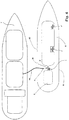
- the device can be arranged centrally (that is, approximately in the region of the longitudinal axis of the ship) or eccentrically (that is, on a port side and / or starboard side of the ship).
- FIG. 4 are exemplified several variants.
- the device 1 In the rear region of the ship, the device 1 is arranged centrally, and in the middle or front region of the ship, two locations are shown on the starboard side at which devices 1 according to the invention are exemplarily placed.
- the device 1 is usually mounted so that the filler neck 2 is aligned to the side, so that a fuel tank can be easily inserted and verkuppelt using the Stahltrosse.
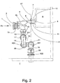
- filling nozzle 2 has an outgoing from its insertion funnel 2a line section 2b, which is directed by 90 ° curved downwards and to which the line 3 is connected.
- the pivot axis X5 is oriented horizontally, the filling nozzle 2 is mounted on a support member 6.
- the holding member 6 is simultaneously mounted in a further pivot bearing 7, which is provided at a fixed location on the structure A of the ship S U-shaped second holder 8.
- the pivot bearing 7 is formed by a pin 9, which sits with its ends in correspondingly shaped, molded into the legs 10,11 of the holder 8 openings and at the same time with sufficient clearance engages by a non-visible bearing eye, in the between the legs 10th , 11 of the holder 8 arranged end portion of the holding member 6 is formed.
- the filler neck 2 carried by the holding member 6 is pivotally mounted, on the one hand, about the vertically aligned pivot axis X7 of the bearing 7 and, on the other hand, about the horizontally oriented pivot axis X5 of the bearing 5 present on the holding member 6.
- the filling nozzle 2 is rotatably connected to the associated end of the line 3.
- the line 3 is formed by four rigid tube elements 13, 14, 15, 16, which consist of a steel material which is protected by a suitable surface coating against corrosive attacks.
- the first pipe element 13 fixedly connected to the filling nozzle 2 is curved by 90 °, so that its end face assigned to the second pipe element 14 is oriented substantially vertically.
- the first tubular element 13 is aligned with respect to the filling nozzle 2 so that the inflow direction RE, with which the fuel flows into the filling nozzle 2, and the outflow direction RA, with which the fuel exits from the first tubular element 13, in plan view ( Fig. 3 ), an angle of about 90 °.
- a first swivel joint 17 is arranged, the pivot axis X17 is aligned horizontally.
- the section 18 of the second tubular element 14 connected to the first tubular swivel joint 17 is curved in an arc of 180 ° and then merges into a straight second section 19 of the tubular element 14.
- the length of the straight second section 19 of the tubular element 14 is dimensioned so that it is in plan view ( Fig. 3 ) is aligned approximately centrally with respect to the longitudinal axis L of the filling nozzle 2.
- the third tubular element 15 is connected to the end of the straight portion 19 of the second tubular element 14.
- the pivot axis X20 of the second swivel joint 20 is also aligned horizontally.
- the third tubular element 15 is curved in an arc of 180 ° and connected via a third swivel joint 21 with the fourth tubular element 16. Also, the pivot axis X21 of the third pivot joint 21 is horizontal aligned, so that the pivot axes X17, X20 and X21 are parallel to each other.
- the fourth tube element 16 like the first tube element 14, is curved at 90 ° and, with its end associated with the flange 4, is coupled to the flange 4 via a fourth swivel joint 22.
- the pivot axis X22 of the fourth swivel joint 22 is vertical, i. transverse to the axes of rotation X17, X20, X21 of the other swivel joints 17,20,21, and aligned in alignment with the pivot axis X7 of the existing bearing 8 on the holder 7.
- the pivot axes X7 and X22 coincide accordingly.
- the filling nozzle 2 is aligned by pivoting about the pivot axes X5 and X7 using in particular the force exerted by the Stahltrosse force so that the arranged at the end of a supplied from the supply vessel V supply line VL tank trunk R safe in the insertion funnel 2a of the filling 2 can be introduced.
- the steel trough for example, adjacent and preferably attack above the filler neck 2 (not shown).
- the bearing 7 and the rotational mobility of the tubular elements 13, 14, 15, 16 pivoting range W of at least 240 ° about the vertical pivot axis X7 allows alignment of the filling nozzle 2 both in the direction of the longitudinal side S1 and in the direction of the longitudinal side S2 of Ship, so that a refueling of the ship S is possible regardless of which of the longitudinal sides S1, S2, the supply vessel V is positioned.
- the filler neck 2 is pivotable in a range of 0 ° to 60 ° about the second pivot axis (X5).
- the device is preferably designed so that the filling nozzle 2 can be pivoted relative to the direction transversely by at least +/- 30 ° degrees.
Landscapes
- Engineering & Computer Science (AREA)
- Mechanical Engineering (AREA)
- Chemical & Material Sciences (AREA)
- Combustion & Propulsion (AREA)
- Ocean & Marine Engineering (AREA)
- Cooling, Air Intake And Gas Exhaust, And Fuel Tank Arrangements In Propulsion Units (AREA)
- Filling Or Discharging Of Gas Storage Vessels (AREA)
Claims (14)
- Dispositif (1) de transfert d'un fluide, en particulier carburant, dans un réservoir (T) d'un navire, présentant une bride (4) associée au réservoir (T) de manière stationnaire, une tubulure de remplissage (2) pour la réception d'un pistolet distributeur de carburant externe et une conduite (3) reliant la bride (4) et la tubulure de remplissage (2), dans lequel la tubulure de remplissage (2) est logée de manière mobile autour d'un palier (7) stationnaire par rapport au réservoir (T), dans lequel la conduite (3) présente une pluralité d'éléments de tube (13, 14, 15, 16), qui sont couplés en rotation au moins en partie l'un par rapport à l'autre et par rapport à la bride et formés de sorte que la tubulure de remplissage (2) peut pivoter autour d'exactement deux axes de pivotement prédéterminés (X7, X5),
dans lequel les axes de pivotement (X7, X5) sont orientés perpendiculairement l'un par rapport à l'autre et sont orientés inclinés selon un angle par rapport à l'axe longitudinal (L) de la tubulure de remplissage (2),
caractérisé en ce que le premier axe de pivotement (X7) est orienté verticalement et le deuxième axe de pivotement (X5) est orienté horizontalement par rapport au navire (S), et
en ce que la tubulure de remplissage (2) est logée de manière pivotante au niveau d'un organe de retenue (6) logé de manière pivotante dans le palier stationnaire (7), dans lequel l'organe de retenue (6) est pivotant autour du premier axe de pivotement (X7) et la tubulure de remplissage (2) est logée au niveau de l'organe de retenue (6) de manière pivotante autour du deuxième axe de pivotement (X5). - Dispositif (1) selon l'une quelconque des revendications précédentes,
caractérisé en ce que l'axe de rotation de l'élément de tube (16) couplé au niveau de la bride (4) et un des axes de pivotement (X7) sont orientés coaxialement l'un par rapport à l'autre. - Dispositif (1) selon l'une quelconque des revendications précédentes,
caractérisé en ce que les éléments de tube (13, 14, 15, 16) de la conduite (3) côté frontal adjacents les uns par rapport aux autres sont reliés les uns aux autres respectivement par une articulation tournante de tube (17, 20, 21, 22). - Dispositif (1) selon la revendication 3, caractérisé en ce que l'axe de rotation (X22) d'une des articulations tournantes de tube (22) est orienté perpendiculairement à l'axe de rotation (X7, X17, X20, X21) d'au moins une autre des articulations tournantes de tube (17, 20, 21).
- Dispositif (1) selon l'une quelconque des revendications précédentes,
caractérisé en ce que la conduite (3) est formée par quatre éléments de tube (13, 14, 15, 16). - Dispositif (1) selon l'une quelconque des revendications précédentes,
caractérisé en ce que la conduite (3) est reliée à la bride stationnaire (4) au moyen d'une articulation tournante de tube (22). - Dispositif (1) selon l'une quelconque des revendications précédentes,
caractérisé en ce que la conduite (3) est reliée solidairement en rotation à la tubulure de remplissage (2). - Dispositif (1) selon l'une quelconque des revendications précédentes,
caractérisé en ce que le deuxième axe de pivotement (X5) est agencé espacé du premier axe de pivotement (X7) du palier stationnaire (7). - Dispositif (1) selon l'une quelconque des revendications précédentes,
caractérisé en ce que la tubulure de remplissage (2) peut pivoter dans une plage de 300° à 60° en passant par 180° autour du premier axe de pivotement (X7) et dans une plage de 0° à 60° autour du deuxième axe de pivotement (X5). - Dispositif (1) selon l'une quelconque des revendications précédentes,
caractérisé en ce que la tubulure de remplissage (2) est reliée de manière amovible à la conduite (3) formée par les éléments de tube (13, 14, 15, 16). - Dispositif (1) selon l'une quelconque des revendications précédentes,
caractérisé par un moyen de fixation pour le rangement et/ou la fixation du dispositif (1). - Navire (S) avec un réservoir (T) et un dispositif (1) réalisé selon l'une quelconque des revendications 1 à 11 pour le transfert d'un fluide dans le réservoir (T).
- Navire (S) selon la revendication 12,
caractérisé en ce que le réservoir (T) est agencé dans la coque de navire et que la tubulure de remplissage (2) est agencée au niveau d'une structure (A) sur le pont du navire (S). - Navire (S) selon la revendication 13,
caractérisé en ce que le dispositif (1) est réalisé et agencé de sorte que la tubulure de remplissage (2) peut pivoter d'au moins +/- 30° degrés par rapport à la direction transversale.
Applications Claiming Priority (1)
| Application Number | Priority Date | Filing Date | Title |
|---|---|---|---|
| DE102012222084.4A DE102012222084B4 (de) | 2012-12-03 | 2012-12-03 | Vorrichtung zum Überleiten eines Fluids in einen Tank und mit einer solchen Vorrichtung ausgestattetes Schiff |
Publications (2)
| Publication Number | Publication Date |
|---|---|
| EP2738136A1 EP2738136A1 (fr) | 2014-06-04 |
| EP2738136B1 true EP2738136B1 (fr) | 2019-04-17 |
Family
ID=49683492
Family Applications (1)
| Application Number | Title | Priority Date | Filing Date |
|---|---|---|---|
| EP13194215.3A Active EP2738136B1 (fr) | 2012-12-03 | 2013-11-25 | Dispositif de transfert de fluide dans un réservoir et navire équipé d'un tel dispositif |
Country Status (3)
| Country | Link |
|---|---|
| US (1) | US9440713B2 (fr) |
| EP (1) | EP2738136B1 (fr) |
| DE (1) | DE102012222084B4 (fr) |
Families Citing this family (2)
| Publication number | Priority date | Publication date | Assignee | Title |
|---|---|---|---|---|
| CN106082098B (zh) * | 2016-07-30 | 2018-05-01 | 衢州乐创节能科技有限公司 | 一种远程控制槽罐加料器 |
| CN114436197B (zh) * | 2022-01-13 | 2023-07-14 | 洛阳涧光特种装备股份有限公司 | 基于定位检测的鹤管自动装车控制系统及其控制方法 |
Family Cites Families (23)
| Publication number | Priority date | Publication date | Assignee | Title |
|---|---|---|---|---|
| NL46167C (fr) * | ||||
| US27343A (en) | 1860-03-06 | Improved plastic compound | ||
| US3199553A (en) * | 1959-11-19 | 1965-08-10 | Parker Hannifin Corp | Ship to ship refueling device |
| US3547402A (en) | 1966-05-17 | 1970-12-15 | Parker Hannifin Corp | Compensated quick-disconnect device |
| USRE27343E (en) * | 1970-11-16 | 1972-04-25 | Material transferring apparatus | |
| US3799197A (en) * | 1972-04-03 | 1974-03-26 | Fmc Corp | Dual jack assembly for marine loading arms |
| FR2181584B1 (fr) * | 1972-04-28 | 1977-07-22 | Luceat Sa | |
| US3921684A (en) * | 1973-12-19 | 1975-11-25 | Lawrence P Allen | Apparatus for coupling oil loading hose and other conduit with a storage tank fill pipe |
| US3896841A (en) * | 1974-03-21 | 1975-07-29 | Fmc Corp | Constant weight-constant dimension coupling assembly for marine loading arms |
| GB1592073A (en) | 1977-02-08 | 1981-07-01 | Fmc Corp | Fluid loading systems |
| FR2384194A1 (fr) * | 1977-03-17 | 1978-10-13 | Fmc Europe | Bras de chargement articule |
| CA1099186A (fr) * | 1978-04-08 | 1981-04-14 | George Fujita | Traduction non-disponible |
| US4231398A (en) * | 1978-09-12 | 1980-11-04 | Fmc Corporation | Cargo hose to marine tanker connection apparatus |
| US4299261A (en) * | 1978-12-11 | 1981-11-10 | Fmc Corporation | Offshore loading system |
| FR2487807B1 (fr) * | 1980-08-04 | 1985-11-15 | Fmc Europe | Procede et agencement hydromecanique permettant, notamment, le degagement d'un bras articule de transfert de produits fluides, en deconnexion d'urgence |
| US4408943A (en) * | 1981-02-27 | 1983-10-11 | Fmc Corporation | Ship-to-ship fluid transfer system |
| US4987925A (en) * | 1989-09-29 | 1991-01-29 | Ltv Energy Products | Loading arm with a lock-down device |
| NO312715B2 (no) * | 1999-10-27 | 2002-06-24 | Statoil Asa | System for offshore overforing av flytendegjort naturgass |
| JP5230438B2 (ja) * | 2005-11-29 | 2013-07-10 | ブルーウォーター・エナジー・サービスィズ・ベー・フェー | タンカー積載アセンブリ |
| FR2902411B1 (fr) * | 2006-06-19 | 2011-02-25 | Technip France | Dispositif de transfert d'un fluide sur un navire, ensemble et procede de transfert associes |
| FR2903653B1 (fr) | 2006-07-13 | 2009-04-10 | Eurodim Sa | Systeme de transfert d'un fluide tel que du gaz naturel liquefie entre un navire tel qu'un methanier navette et une unite flottante ou fixe. |
| FR2914903B1 (fr) * | 2007-04-12 | 2010-05-28 | Technip France | Dispositif de transfert d'un fluide sur un navire, navire, ensemble de transfert et procede associe |
| FR2931451B1 (fr) * | 2008-05-22 | 2010-12-17 | Fmc Technologies Sa | Dispositif de commande pour systeme de chargement et/ou dechargement de fluides |
-
2012
- 2012-12-03 DE DE102012222084.4A patent/DE102012222084B4/de not_active Expired - Fee Related
-
2013
- 2013-11-25 EP EP13194215.3A patent/EP2738136B1/fr active Active
- 2013-11-26 US US14/090,088 patent/US9440713B2/en not_active Expired - Fee Related
Non-Patent Citations (1)
| Title |
|---|
| None * |
Also Published As
| Publication number | Publication date |
|---|---|
| US9440713B2 (en) | 2016-09-13 |
| US20140150707A1 (en) | 2014-06-05 |
| DE102012222084B4 (de) | 2017-06-01 |
| DE102012222084A1 (de) | 2014-06-05 |
| EP2738136A1 (fr) | 2014-06-04 |
Similar Documents
| Publication | Publication Date | Title |
|---|---|---|
| DE60107969T2 (de) | Anordnung mit gelenkarm zum laden und entladen von produkten, insbesondere von strömungsfähigen produkten | |
| DE60216266T2 (de) | Flüssigkeitstransferierungssystem, insbesondere lng, zwischen einem transportfahrzeug, wie ein schiff, und eine empfangs- oder lieferstation für dieses produkt | |
| DE2613851C3 (de) | Vorrichtung zum Festmachen eines Schiffes | |
| EP2718604B1 (fr) | Accouplement à coquilles et son utilisation | |
| DE2858189C2 (de) | Gegliederter Ladearm zum Überführen von Flüssigkeit | |
| DE60027488T2 (de) | Seetüchtiger Schleppzug aus Leichtern | |
| DE602004005574T2 (de) | Verfahren zum schneiden und entfernen von unterwasserrohrleitungen und vorrichtung zur durchführung des verfahrens | |
| EP2757067B1 (fr) | Dispositif de bras de chargement | |
| DE102012224529A1 (de) | Arbeitsgerät mit Drehkopf-Trennstelle | |
| EP0166800B1 (fr) | Tête de ligne pour dispositif de ravitaillement en carburant | |
| DE2514909B2 (de) | Verfahren und Vorrichtung zum Airschließen einer unterseeischen Zentralstation an Bohrlochköpfe und Förderleitungen | |
| DE1908553A1 (de) | Rohrkupplung | |
| EP2738136B1 (fr) | Dispositif de transfert de fluide dans un réservoir et navire équipé d'un tel dispositif | |
| EP3800299B1 (fr) | Équipement, en particulier chargeur sur roues | |
| DE2040858A1 (de) | Schwenkbare Begasungsvorrichtung mit niedrigem Durchflusswiderstand | |
| DE2745254A1 (de) | Schiffsladearm-bunkerungsanordnung | |
| DE3048909C2 (fr) | ||
| EP2789531B1 (fr) | Plate-forme flottante de chargement, de stockage et de production de gnl et/ou de gpl | |
| DE8003719U1 (de) | Gegliederter Ladearm | |
| DE102019111496B3 (de) | Auslegerarm mit hindurchgeführtem Halteelement | |
| EP1630100B1 (fr) | Tête de ligne pour dispositif de ravitaillement en carburant | |
| DE69204249T2 (de) | Halterungsvorrichtung für öltransportschlauch oder -rohr. | |
| EP0926061B1 (fr) | Dispositif à bord d'un bateau pour mollir un câble de remorquage pour un véhicule sous-marine auto propulsé | |
| DE2727984B2 (de) | Ruder für Wasserfahrzeuge | |
| DE2710404C2 (de) | Vorrichtung zur Herstellung einer Verbindung zwischen einem Rohrstützausleger und einem Rohrlegeschiff |
Legal Events
| Date | Code | Title | Description |
|---|---|---|---|
| PUAI | Public reference made under article 153(3) epc to a published international application that has entered the european phase |
Free format text: ORIGINAL CODE: 0009012 |
|
| 17P | Request for examination filed |
Effective date: 20131125 |
|
| AK | Designated contracting states |
Kind code of ref document: A1 Designated state(s): AL AT BE BG CH CY CZ DE DK EE ES FI FR GB GR HR HU IE IS IT LI LT LU LV MC MK MT NL NO PL PT RO RS SE SI SK SM TR |
|
| AX | Request for extension of the european patent |
Extension state: BA ME |
|
| R17P | Request for examination filed (corrected) |
Effective date: 20141204 |
|
| RBV | Designated contracting states (corrected) |
Designated state(s): AL AT BE BG CH CY CZ DE DK EE ES FI FR GB GR HR HU IE IS IT LI LT LU LV MC MK MT NL NO PL PT RO RS SE SI SK SM TR |
|
| STAA | Information on the status of an ep patent application or granted ep patent |
Free format text: STATUS: EXAMINATION IS IN PROGRESS |
|
| 17Q | First examination report despatched |
Effective date: 20170216 |
|
| TPAC | Observations filed by third parties |
Free format text: ORIGINAL CODE: EPIDOSNTIPA |
|
| GRAP | Despatch of communication of intention to grant a patent |
Free format text: ORIGINAL CODE: EPIDOSNIGR1 |
|
| STAA | Information on the status of an ep patent application or granted ep patent |
Free format text: STATUS: GRANT OF PATENT IS INTENDED |
|
| INTG | Intention to grant announced |
Effective date: 20181109 |
|
| GRAS | Grant fee paid |
Free format text: ORIGINAL CODE: EPIDOSNIGR3 |
|
| GRAA | (expected) grant |
Free format text: ORIGINAL CODE: 0009210 |
|
| STAA | Information on the status of an ep patent application or granted ep patent |
Free format text: STATUS: THE PATENT HAS BEEN GRANTED |
|
| AK | Designated contracting states |
Kind code of ref document: B1 Designated state(s): AL AT BE BG CH CY CZ DE DK EE ES FI FR GB GR HR HU IE IS IT LI LT LU LV MC MK MT NL NO PL PT RO RS SE SI SK SM TR |
|
| REG | Reference to a national code |
Ref country code: GB Ref legal event code: FG4D Free format text: NOT ENGLISH |
|
| REG | Reference to a national code |
Ref country code: CH Ref legal event code: EP |
|
| REG | Reference to a national code |
Ref country code: DE Ref legal event code: R096 Ref document number: 502013012644 Country of ref document: DE |
|
| REG | Reference to a national code |
Ref country code: AT Ref legal event code: REF Ref document number: 1121331 Country of ref document: AT Kind code of ref document: T Effective date: 20190515 Ref country code: IE Ref legal event code: FG4D Free format text: LANGUAGE OF EP DOCUMENT: GERMAN |
|
| REG | Reference to a national code |
Ref country code: NL Ref legal event code: FP |
|
| REG | Reference to a national code |
Ref country code: LT Ref legal event code: MG4D |
|
| PG25 | Lapsed in a contracting state [announced via postgrant information from national office to epo] |
Ref country code: FI Free format text: LAPSE BECAUSE OF FAILURE TO SUBMIT A TRANSLATION OF THE DESCRIPTION OR TO PAY THE FEE WITHIN THE PRESCRIBED TIME-LIMIT Effective date: 20190417 Ref country code: NO Free format text: LAPSE BECAUSE OF FAILURE TO SUBMIT A TRANSLATION OF THE DESCRIPTION OR TO PAY THE FEE WITHIN THE PRESCRIBED TIME-LIMIT Effective date: 20190717 Ref country code: LT Free format text: LAPSE BECAUSE OF FAILURE TO SUBMIT A TRANSLATION OF THE DESCRIPTION OR TO PAY THE FEE WITHIN THE PRESCRIBED TIME-LIMIT Effective date: 20190417 Ref country code: ES Free format text: LAPSE BECAUSE OF FAILURE TO SUBMIT A TRANSLATION OF THE DESCRIPTION OR TO PAY THE FEE WITHIN THE PRESCRIBED TIME-LIMIT Effective date: 20190417 Ref country code: PT Free format text: LAPSE BECAUSE OF FAILURE TO SUBMIT A TRANSLATION OF THE DESCRIPTION OR TO PAY THE FEE WITHIN THE PRESCRIBED TIME-LIMIT Effective date: 20190817 Ref country code: HR Free format text: LAPSE BECAUSE OF FAILURE TO SUBMIT A TRANSLATION OF THE DESCRIPTION OR TO PAY THE FEE WITHIN THE PRESCRIBED TIME-LIMIT Effective date: 20190417 Ref country code: AL Free format text: LAPSE BECAUSE OF FAILURE TO SUBMIT A TRANSLATION OF THE DESCRIPTION OR TO PAY THE FEE WITHIN THE PRESCRIBED TIME-LIMIT Effective date: 20190417 Ref country code: SE Free format text: LAPSE BECAUSE OF FAILURE TO SUBMIT A TRANSLATION OF THE DESCRIPTION OR TO PAY THE FEE WITHIN THE PRESCRIBED TIME-LIMIT Effective date: 20190417 |
|
| PG25 | Lapsed in a contracting state [announced via postgrant information from national office to epo] |
Ref country code: LV Free format text: LAPSE BECAUSE OF FAILURE TO SUBMIT A TRANSLATION OF THE DESCRIPTION OR TO PAY THE FEE WITHIN THE PRESCRIBED TIME-LIMIT Effective date: 20190417 Ref country code: GR Free format text: LAPSE BECAUSE OF FAILURE TO SUBMIT A TRANSLATION OF THE DESCRIPTION OR TO PAY THE FEE WITHIN THE PRESCRIBED TIME-LIMIT Effective date: 20190718 Ref country code: PL Free format text: LAPSE BECAUSE OF FAILURE TO SUBMIT A TRANSLATION OF THE DESCRIPTION OR TO PAY THE FEE WITHIN THE PRESCRIBED TIME-LIMIT Effective date: 20190417 Ref country code: RS Free format text: LAPSE BECAUSE OF FAILURE TO SUBMIT A TRANSLATION OF THE DESCRIPTION OR TO PAY THE FEE WITHIN THE PRESCRIBED TIME-LIMIT Effective date: 20190417 Ref country code: BG Free format text: LAPSE BECAUSE OF FAILURE TO SUBMIT A TRANSLATION OF THE DESCRIPTION OR TO PAY THE FEE WITHIN THE PRESCRIBED TIME-LIMIT Effective date: 20190717 |
|
| PG25 | Lapsed in a contracting state [announced via postgrant information from national office to epo] |
Ref country code: IS Free format text: LAPSE BECAUSE OF FAILURE TO SUBMIT A TRANSLATION OF THE DESCRIPTION OR TO PAY THE FEE WITHIN THE PRESCRIBED TIME-LIMIT Effective date: 20190817 |
|
| REG | Reference to a national code |
Ref country code: DE Ref legal event code: R097 Ref document number: 502013012644 Country of ref document: DE |
|
| PG25 | Lapsed in a contracting state [announced via postgrant information from national office to epo] |
Ref country code: RO Free format text: LAPSE BECAUSE OF FAILURE TO SUBMIT A TRANSLATION OF THE DESCRIPTION OR TO PAY THE FEE WITHIN THE PRESCRIBED TIME-LIMIT Effective date: 20190417 Ref country code: CZ Free format text: LAPSE BECAUSE OF FAILURE TO SUBMIT A TRANSLATION OF THE DESCRIPTION OR TO PAY THE FEE WITHIN THE PRESCRIBED TIME-LIMIT Effective date: 20190417 Ref country code: SK Free format text: LAPSE BECAUSE OF FAILURE TO SUBMIT A TRANSLATION OF THE DESCRIPTION OR TO PAY THE FEE WITHIN THE PRESCRIBED TIME-LIMIT Effective date: 20190417 Ref country code: EE Free format text: LAPSE BECAUSE OF FAILURE TO SUBMIT A TRANSLATION OF THE DESCRIPTION OR TO PAY THE FEE WITHIN THE PRESCRIBED TIME-LIMIT Effective date: 20190417 Ref country code: DK Free format text: LAPSE BECAUSE OF FAILURE TO SUBMIT A TRANSLATION OF THE DESCRIPTION OR TO PAY THE FEE WITHIN THE PRESCRIBED TIME-LIMIT Effective date: 20190417 |
|
| PLBE | No opposition filed within time limit |
Free format text: ORIGINAL CODE: 0009261 |
|
| STAA | Information on the status of an ep patent application or granted ep patent |
Free format text: STATUS: NO OPPOSITION FILED WITHIN TIME LIMIT |
|
| PG25 | Lapsed in a contracting state [announced via postgrant information from national office to epo] |
Ref country code: SM Free format text: LAPSE BECAUSE OF FAILURE TO SUBMIT A TRANSLATION OF THE DESCRIPTION OR TO PAY THE FEE WITHIN THE PRESCRIBED TIME-LIMIT Effective date: 20190417 |
|
| 26N | No opposition filed |
Effective date: 20200120 |
|
| PG25 | Lapsed in a contracting state [announced via postgrant information from national office to epo] |
Ref country code: TR Free format text: LAPSE BECAUSE OF FAILURE TO SUBMIT A TRANSLATION OF THE DESCRIPTION OR TO PAY THE FEE WITHIN THE PRESCRIBED TIME-LIMIT Effective date: 20190417 |
|
| PG25 | Lapsed in a contracting state [announced via postgrant information from national office to epo] |
Ref country code: SI Free format text: LAPSE BECAUSE OF FAILURE TO SUBMIT A TRANSLATION OF THE DESCRIPTION OR TO PAY THE FEE WITHIN THE PRESCRIBED TIME-LIMIT Effective date: 20190417 |
|
| REG | Reference to a national code |
Ref country code: CH Ref legal event code: PL |
|
| PG25 | Lapsed in a contracting state [announced via postgrant information from national office to epo] |
Ref country code: LI Free format text: LAPSE BECAUSE OF NON-PAYMENT OF DUE FEES Effective date: 20191130 Ref country code: MC Free format text: LAPSE BECAUSE OF FAILURE TO SUBMIT A TRANSLATION OF THE DESCRIPTION OR TO PAY THE FEE WITHIN THE PRESCRIBED TIME-LIMIT Effective date: 20190417 Ref country code: CH Free format text: LAPSE BECAUSE OF NON-PAYMENT OF DUE FEES Effective date: 20191130 Ref country code: LU Free format text: LAPSE BECAUSE OF NON-PAYMENT OF DUE FEES Effective date: 20191125 |
|
| REG | Reference to a national code |
Ref country code: BE Ref legal event code: MM Effective date: 20191130 |
|
| PG25 | Lapsed in a contracting state [announced via postgrant information from national office to epo] |
Ref country code: IE Free format text: LAPSE BECAUSE OF NON-PAYMENT OF DUE FEES Effective date: 20191125 |
|
| PG25 | Lapsed in a contracting state [announced via postgrant information from national office to epo] |
Ref country code: BE Free format text: LAPSE BECAUSE OF NON-PAYMENT OF DUE FEES Effective date: 20191130 |
|
| REG | Reference to a national code |
Ref country code: AT Ref legal event code: MM01 Ref document number: 1121331 Country of ref document: AT Kind code of ref document: T Effective date: 20191125 |
|
| PG25 | Lapsed in a contracting state [announced via postgrant information from national office to epo] |
Ref country code: AT Free format text: LAPSE BECAUSE OF NON-PAYMENT OF DUE FEES Effective date: 20191125 |
|
| PG25 | Lapsed in a contracting state [announced via postgrant information from national office to epo] |
Ref country code: CY Free format text: LAPSE BECAUSE OF FAILURE TO SUBMIT A TRANSLATION OF THE DESCRIPTION OR TO PAY THE FEE WITHIN THE PRESCRIBED TIME-LIMIT Effective date: 20190417 |
|
| PG25 | Lapsed in a contracting state [announced via postgrant information from national office to epo] |
Ref country code: MT Free format text: LAPSE BECAUSE OF FAILURE TO SUBMIT A TRANSLATION OF THE DESCRIPTION OR TO PAY THE FEE WITHIN THE PRESCRIBED TIME-LIMIT Effective date: 20190417 Ref country code: HU Free format text: LAPSE BECAUSE OF FAILURE TO SUBMIT A TRANSLATION OF THE DESCRIPTION OR TO PAY THE FEE WITHIN THE PRESCRIBED TIME-LIMIT; INVALID AB INITIO Effective date: 20131125 |
|
| REG | Reference to a national code |
Ref country code: DE Ref legal event code: R081 Ref document number: 502013012644 Country of ref document: DE Owner name: NVL B.V. & CO. KG, DE Free format text: FORMER OWNER: FR. LUERSSEN WERFT GMBH & CO.KG, 28759 BREMEN, DE |
|
| REG | Reference to a national code |
Ref country code: NL Ref legal event code: PD Owner name: NVL B.V. & CO. KG; DE Free format text: DETAILS ASSIGNMENT: CHANGE OF OWNER(S), ASSIGNMENT; FORMER OWNER NAME: FR. LUERSSEN WERFT GMBH & CO. KG Effective date: 20220107 |
|
| PG25 | Lapsed in a contracting state [announced via postgrant information from national office to epo] |
Ref country code: MK Free format text: LAPSE BECAUSE OF FAILURE TO SUBMIT A TRANSLATION OF THE DESCRIPTION OR TO PAY THE FEE WITHIN THE PRESCRIBED TIME-LIMIT Effective date: 20190417 |
|
| REG | Reference to a national code |
Ref country code: GB Ref legal event code: 732E Free format text: REGISTERED BETWEEN 20220616 AND 20220622 |
|
| REG | Reference to a national code |
Ref country code: DE Ref legal event code: R082 Ref document number: 502013012644 Country of ref document: DE Representative=s name: FIELDFISHER PARTNERSCHAFT VON RECHTSANWAELTEN , DE |
|
| PGFP | Annual fee paid to national office [announced via postgrant information from national office to epo] |
Ref country code: IT Payment date: 20241105 Year of fee payment: 12 |
|
| PGFP | Annual fee paid to national office [announced via postgrant information from national office to epo] |
Ref country code: GB Payment date: 20250923 Year of fee payment: 13 |
|
| PGFP | Annual fee paid to national office [announced via postgrant information from national office to epo] |
Ref country code: FR Payment date: 20250825 Year of fee payment: 13 |
|
| PGFP | Annual fee paid to national office [announced via postgrant information from national office to epo] |
Ref country code: NL Payment date: 20251118 Year of fee payment: 13 |
|
| PGFP | Annual fee paid to national office [announced via postgrant information from national office to epo] |
Ref country code: DE Payment date: 20250821 Year of fee payment: 13 |