EP2735773B1 - Pinion Gear Assembly - Google Patents
Pinion Gear Assembly Download PDFInfo
- Publication number
- EP2735773B1 EP2735773B1 EP13184928.3A EP13184928A EP2735773B1 EP 2735773 B1 EP2735773 B1 EP 2735773B1 EP 13184928 A EP13184928 A EP 13184928A EP 2735773 B1 EP2735773 B1 EP 2735773B1
- Authority
- EP
- European Patent Office
- Prior art keywords
- collar
- pinion
- end surface
- bearing
- hub
- Prior art date
- Legal status (The legal status is an assumption and is not a legal conclusion. Google has not performed a legal analysis and makes no representation as to the accuracy of the status listed.)
- Active
Links
- 230000000712 assembly Effects 0.000 description 9
- 238000000429 assembly Methods 0.000 description 9
- 239000000463 material Substances 0.000 description 6
- 230000013011 mating Effects 0.000 description 3
- 238000005452 bending Methods 0.000 description 2
- 238000003754 machining Methods 0.000 description 2
- 229910001092 metal group alloy Inorganic materials 0.000 description 2
- 238000010276 construction Methods 0.000 description 1
- 239000002184 metal Substances 0.000 description 1
- 239000007787 solid Substances 0.000 description 1
- 239000002699 waste material Substances 0.000 description 1
Images


Classifications
-
- F—MECHANICAL ENGINEERING; LIGHTING; HEATING; WEAPONS; BLASTING
- F16—ENGINEERING ELEMENTS AND UNITS; GENERAL MEASURES FOR PRODUCING AND MAINTAINING EFFECTIVE FUNCTIONING OF MACHINES OR INSTALLATIONS; THERMAL INSULATION IN GENERAL
- F16H—GEARING
- F16H55/00—Elements with teeth or friction surfaces for conveying motion; Worms, pulleys or sheaves for gearing mechanisms
- F16H55/02—Toothed members; Worms
- F16H55/17—Toothed wheels
-
- F—MECHANICAL ENGINEERING; LIGHTING; HEATING; WEAPONS; BLASTING
- F16—ENGINEERING ELEMENTS AND UNITS; GENERAL MEASURES FOR PRODUCING AND MAINTAINING EFFECTIVE FUNCTIONING OF MACHINES OR INSTALLATIONS; THERMAL INSULATION IN GENERAL
- F16C—SHAFTS; FLEXIBLE SHAFTS; ELEMENTS OR CRANKSHAFT MECHANISMS; ROTARY BODIES OTHER THAN GEARING ELEMENTS; BEARINGS
- F16C17/00—Sliding-contact bearings for exclusively rotary movement
- F16C17/02—Sliding-contact bearings for exclusively rotary movement for radial load only
-
- F—MECHANICAL ENGINEERING; LIGHTING; HEATING; WEAPONS; BLASTING
- F16—ENGINEERING ELEMENTS AND UNITS; GENERAL MEASURES FOR PRODUCING AND MAINTAINING EFFECTIVE FUNCTIONING OF MACHINES OR INSTALLATIONS; THERMAL INSULATION IN GENERAL
- F16C—SHAFTS; FLEXIBLE SHAFTS; ELEMENTS OR CRANKSHAFT MECHANISMS; ROTARY BODIES OTHER THAN GEARING ELEMENTS; BEARINGS
- F16C35/00—Rigid support of bearing units; Housings, e.g. caps, covers
- F16C35/02—Rigid support of bearing units; Housings, e.g. caps, covers in the case of sliding-contact bearings
-
- F—MECHANICAL ENGINEERING; LIGHTING; HEATING; WEAPONS; BLASTING
- F16—ENGINEERING ELEMENTS AND UNITS; GENERAL MEASURES FOR PRODUCING AND MAINTAINING EFFECTIVE FUNCTIONING OF MACHINES OR INSTALLATIONS; THERMAL INSULATION IN GENERAL
- F16C—SHAFTS; FLEXIBLE SHAFTS; ELEMENTS OR CRANKSHAFT MECHANISMS; ROTARY BODIES OTHER THAN GEARING ELEMENTS; BEARINGS
- F16C35/00—Rigid support of bearing units; Housings, e.g. caps, covers
- F16C35/04—Rigid support of bearing units; Housings, e.g. caps, covers in the case of ball or roller bearings
- F16C35/06—Mounting or dismounting of ball or roller bearings; Fixing them onto shaft or in housing
- F16C35/07—Fixing them on the shaft or housing with interposition of an element
- F16C35/073—Fixing them on the shaft or housing with interposition of an element between shaft and inner race ring
-
- F—MECHANICAL ENGINEERING; LIGHTING; HEATING; WEAPONS; BLASTING
- F16—ENGINEERING ELEMENTS AND UNITS; GENERAL MEASURES FOR PRODUCING AND MAINTAINING EFFECTIVE FUNCTIONING OF MACHINES OR INSTALLATIONS; THERMAL INSULATION IN GENERAL
- F16C—SHAFTS; FLEXIBLE SHAFTS; ELEMENTS OR CRANKSHAFT MECHANISMS; ROTARY BODIES OTHER THAN GEARING ELEMENTS; BEARINGS
- F16C19/00—Bearings with rolling contact, for exclusively rotary movement
- F16C19/22—Bearings with rolling contact, for exclusively rotary movement with bearing rollers essentially of the same size in one or more circular rows, e.g. needle bearings
- F16C19/24—Bearings with rolling contact, for exclusively rotary movement with bearing rollers essentially of the same size in one or more circular rows, e.g. needle bearings for radial load mainly
- F16C19/26—Bearings with rolling contact, for exclusively rotary movement with bearing rollers essentially of the same size in one or more circular rows, e.g. needle bearings for radial load mainly with a single row of rollers
-
- F—MECHANICAL ENGINEERING; LIGHTING; HEATING; WEAPONS; BLASTING
- F16—ENGINEERING ELEMENTS AND UNITS; GENERAL MEASURES FOR PRODUCING AND MAINTAINING EFFECTIVE FUNCTIONING OF MACHINES OR INSTALLATIONS; THERMAL INSULATION IN GENERAL
- F16C—SHAFTS; FLEXIBLE SHAFTS; ELEMENTS OR CRANKSHAFT MECHANISMS; ROTARY BODIES OTHER THAN GEARING ELEMENTS; BEARINGS
- F16C2361/00—Apparatus or articles in engineering in general
- F16C2361/61—Toothed gear systems, e.g. support of pinion shafts
-
- F—MECHANICAL ENGINEERING; LIGHTING; HEATING; WEAPONS; BLASTING
- F16—ENGINEERING ELEMENTS AND UNITS; GENERAL MEASURES FOR PRODUCING AND MAINTAINING EFFECTIVE FUNCTIONING OF MACHINES OR INSTALLATIONS; THERMAL INSULATION IN GENERAL
- F16H—GEARING
- F16H1/00—Toothed gearings for conveying rotary motion
- F16H1/02—Toothed gearings for conveying rotary motion without gears having orbital motion
- F16H1/04—Toothed gearings for conveying rotary motion without gears having orbital motion involving only two intermeshing members
- F16H1/12—Toothed gearings for conveying rotary motion without gears having orbital motion involving only two intermeshing members with non-parallel axes
- F16H1/14—Toothed gearings for conveying rotary motion without gears having orbital motion involving only two intermeshing members with non-parallel axes comprising conical gears only
-
- F—MECHANICAL ENGINEERING; LIGHTING; HEATING; WEAPONS; BLASTING
- F16—ENGINEERING ELEMENTS AND UNITS; GENERAL MEASURES FOR PRODUCING AND MAINTAINING EFFECTIVE FUNCTIONING OF MACHINES OR INSTALLATIONS; THERMAL INSULATION IN GENERAL
- F16H—GEARING
- F16H48/00—Differential gearings
- F16H48/38—Constructional details
- F16H48/42—Constructional details characterised by features of the input shafts, e.g. mounting of drive gears thereon
- F16H2048/423—Constructional details characterised by features of the input shafts, e.g. mounting of drive gears thereon characterised by bearing arrangement
- F16H2048/426—Constructional details characterised by features of the input shafts, e.g. mounting of drive gears thereon characterised by bearing arrangement characterised by spigot bearing arrangement, e.g. bearing for supporting the free end of the drive shaft pinion
-
- Y—GENERAL TAGGING OF NEW TECHNOLOGICAL DEVELOPMENTS; GENERAL TAGGING OF CROSS-SECTIONAL TECHNOLOGIES SPANNING OVER SEVERAL SECTIONS OF THE IPC; TECHNICAL SUBJECTS COVERED BY FORMER USPC CROSS-REFERENCE ART COLLECTIONS [XRACs] AND DIGESTS
- Y10—TECHNICAL SUBJECTS COVERED BY FORMER USPC
- Y10T—TECHNICAL SUBJECTS COVERED BY FORMER US CLASSIFICATION
- Y10T74/00—Machine element or mechanism
- Y10T74/19—Gearing
- Y10T74/1987—Rotary bodies
Definitions
- the present application relates to a pinion gear assembly.
- a pinion gear assembly may include a pinion, a collar, and a bearing.
- the pinion may extend along an axis and may have a gear portion and a hub portion.
- the collar may have a collar hole that may receive the hub portion.
- the bearing may have a bearing hole that may receive the collar.
- the collar may be fixedly disposed on the hub portion and the bearing may be fixedly disposed on the collar.
- a pinion gear assembly may include a pinion, a collar, a bearing, and a collar snap ring.
- the pinion may extend along an axis.
- the pinion may have a gear portion and a hub portion disposed proximate the gear portion.
- the collar may have a collar hole and a collar snap ring groove.
- the collar hole may receive the hub portion.
- the bearing may define a bearing hole that may receive the collar.
- the collar snap ring may be disposed in the collar snap ring groove and may inhibit movement of the bearing with respect to the collar.
- a pinion gear assembly may include a pinion, a collar, a hub snap ring, and a bearing.
- the pinion may have a gear portion and a hub portion disposed proximate the gear portion.
- the hub portion may extend from a pinion end surface and may have a hub snap ring groove.
- the collar may define a collar hole that may receive the hub portion.
- the hub snap ring may be received in the hub snap ring groove and may engage the collar to inhibit movement of the collar with respect to the pinion.
- the bearing may define a bearing hole that may receive the collar.
- the bearing may be fixedly disposed on collar.
- the pinion gear assembly 10 may be configured for use in a vehicle, such as a motor vehicle like a truck, bus, farm equipment, or cargo loading equipment for land, air, or marine vessels.
- the pinion gear assembly 10 may be part of an axle assembly or differential that may be configured to transmit torque to vehicle traction wheel assemblies and permit the traction wheel assemblies to rotate at different velocities.
- the pinion gear assembly 10 may be rotatably supported by one or more bearings and may rotate about an axis 12.
- the pinion gear assembly 10 may be coupled to a torque source, such as a vehicle drivetrain component like a motor. Torque that is provided to the pinion gear assembly 10 may be transmitted to another component, such as a ring gear. Torque may be transmitted from the ring gear to at least one axle and from an axle to at least one corresponding wheel hub and/or traction wheel assembly.
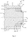
- the pinion gear assembly 10 may include a pinion 20, a collar 22, and a bearing 24.
- the pinion 20 may extend along the axis 12.
- the pinion 20 may be made of any suitable material, such as a metal alloy.
- the pinion 20 may have a shaft portion 30, a gear portion 32, and a hub portion 34.
- the pinion 20 may have a unitary or one piece construction in which the shaft portion 30, gear portion 32, and hub portion 34 are integrally formed.
- the shaft portion 30 may extend from a first pinion end surface 36 of the pinion 20 toward a second pinion end surface 38 of the pinion 20.
- the shaft portion 30 may extend from the first pinion end surface 36 to the gear portion 32.
- the shaft portion 30 may be generally cylindrical or may have one or more substantially cylindrical exterior surfaces.
- the shaft portion 30 may be coupled to a torque source and may be rotatably supported by one or more bearing assemblies.
- the gear portion 32 may be disposed adjacent to and may extend outwardly from the shaft portion 30.
- the gear portion 32 may include a set of teeth 40.
- the teeth 40 may be arranged about the axis 12 and provided in a repeating pattern.
- the gear portion 32 may be configured as a hypoid gear or a bevel gear, such as a plain bevel gear or a spiral bevel gear.
- the gear portion 32 may have a generally tapered or truncated conical shape that may become narrower (e.g., disposed closer to the axis 12) in a direction that extends from the first pinion end surface 36 toward the second pinion end surface 38.
- the teeth 40 may be provided in the pinion 20 by cutting or removing material from the gear portion 32.
- the hub portion 34 may be disposed proximate the gear portion 32.
- the hub portion 34 may extend from the gear portion 32 to the second pinion end surface 38 of the pinion 20.
- the hub portion 34 may be disposed at an end of the pinion 20.
- the hub portion 34 may be generally cylindrical in shape and may be centered about the axis 12.
- the hub portion 34 may have an outer hub surface 42 that may extend from the second pinion end surface 38 toward the gear portion 32 and may at least partially define a circumference of the hub portion 34.
- the hub portion 34 or outer hub surface 42 may have a smaller diameter than the shaft portion 30 and the gear portion 32 to provide additional clearance for a gear tooth cutting tool as will be discussed in more detail below.
- the hub portion 34 may also include a hub keyhole 44.
- the hub keyhole 44 may be disposed between the second pinion end surface 38 and the gear portion 32 and may extend from the outer hub surface 42 toward the axis 12.
- the hub keyhole 44 may be configured as a blind hole in one or more embodiments.
- the gear portion 32 and/or hub portion 34 may include one or more shoulders.
- a first shoulder 50 and a second shoulder 52 are provided.
- the first and second shoulders 50, 52 may help position and inhibit axial movement of the collar 22 and bearing 24 as will be discussed in more detail below.
- the first shoulder 50 may be provided with or may be disposed adjacent to the hub portion 34.
- the first shoulder 50 may extend radially outward with respect to the axis 12 from the outer hub surface 42.
- the second shoulder 52 may be spaced apart from the first shoulder 50 and may be disposed closer to the first pinion end surface 36 of the pinion 20.
- the second shoulder 52 may also extend radially outward with respect to the axis 12.
- the second shoulder 52 may be positioned further from the axis 12 than the first shoulder 50.
- the first shoulder 50 and/or second shoulder 52 or portions thereof may be discontinuous or interrupted by grooves disposed between adjacent gear teeth 40 in one or more embodiments.
- the collar 22 may be fixedly disposed on the pinion 20.
- the collar 22 may be configured as a ring or a hollow cylinder that may extend around the axis 12.
- the collar 22 may include a first end surface 60, a second end surface 62, an outer surface 64, an inner surface 66, a collar keyhole 68, and a collar snap ring groove 70.
- the collar 22 may be made of a metal or metal alloy and may be hardened to withstand load forces.
- the first end surface 60 may face toward and may engage the first shoulder 50. In at least one embodiment, the first end surface 60 may be disposed substantially perpendicular with respect to the axis 12.
- the second end surface 62 may be spaced apart from and disposed opposite the first end surface 60.
- the second end surface 62 may also extend substantially perpendicular with respect to the axis 12 and may be disposed proximate the second pinion end surface 38. In various embodiments, the second end surface 62 may be aligned with or offset from the second pinion end surface 38.
- the outer surface 64 may extend from the first end surface 60 to or toward the second end surface 62.
- the outer surface 64 may be an outer circumferential surface of the collar 22.
- the inner surface 66 may be disposed opposite the outer surface 64.
- the inner surface 66 may be an inner circumferential surface of the collar 22 and may at least partially define a collar hole 72.
- the collar hole 72 may extend from the first end surface 60 to the second end surface 62 and may receive the hub portion 34.
- the inner surface 66 may engage the outer hub surface 42.
- the collar keyhole 68 may extend from the outer surface 64 to the inner surface 66.
- the collar keyhole 68 may be aligned with the hub keyhole 44 and may be configured to receive a key 74.
- the key 74 may be press fit into the hub keyhole 44 and/or the collar keyhole 68 to inhibit movement of the collar 22 with respect to the pinion 20.
- the key 74 may be installed before the bearing 24 is positioned on the collar 22.
- the key 74 may have any suitable configuration.
- the key 74 may have a solid or hollow configuration and may be configured as a pin in one or more embodiments.
- the collar snap ring groove 70 may be provided on the collar 22.
- the collar snap ring groove 70 may be disposed between the collar keyhole 68 and the second end surface 62.
- the collar snap ring groove 70 may extend continuously around the axis 12 and may extend from the outer surface 64 toward the inner surface 66 and may be spaced apart from the collar hole 72.
- the collar snap ring groove 70 may be configured to receive a collar snap ring 78.
- the collar snap ring 78 may be disposed in the collar snap ring groove 70 to inhibit axial movement of the bearing 24 with respect to the collar 22.
- the collar snap ring 78 may engage the bearing 24 to inhibit removal of the bearing 24 from the collar 22.
- the bearing 24 may be fixedly disposed on the collar 22.
- the bearing 24 may be an inner race of a bearing assembly that rotatably supports the pinion 20.
- the bearing 24 may include a first bearing end surface 80, a second bearing end surface 82, an outer bearing surface 84, and an inner bearing surface 86.
- the first bearing end surface 80 may face toward and may engage a part of the pinion 20, such as the second shoulder 52. In at least one embodiment, the first bearing end surface 80 may be disposed substantially perpendicular with respect to the axis 12.
- the first bearing end surface 80 may at least partially define a flange 90 that extends outwardly from the outer bearing surface 84. The flange 90 may engage and help position a set of rollers or roller bearings that may be provided with a bearing assembly in one or more embodiments.
- the second bearing end surface 82 may be spaced apart from and disposed opposite the first bearing end surface 80.
- the second bearing end surface 82 may extend substantially perpendicular with respect to the axis 12 and may be disposed proximate the second pinion end surface 38. In various embodiments, the second bearing end surface 82 may be aligned with or offset from the second pinion end surface 38.
- the collar snap ring 78 may engage the second bearing end surface 82 to inhibit axial movement of the bearing 24.
- the outer bearing surface 84 may extend from the flange 90 to the second bearing end surface 82.
- the outer bearing surface 84 may be an outer circumferential surface of the bearing 24 and may engage and support a set of rollers or roller bearings in one or more embodiments.
- the outer bearing surface 84 may have a smaller diameter than the flange 90.
- the inner bearing surface 86 may be disposed opposite the outer bearing surface 84.
- the inner bearing surface 86 may be an inner circumferential surface of the bearing 24 and may at least partially define a bearing hole 92.
- the bearing hole 92 may extend from the first bearing end surface 80 to the second bearing end surface 82 and may receive the collar 22 and/or the hub portion 34.
- the inner bearing surface 86 may engage the outer surface 64 of the collar 22 and/or the pinion 20.
- each pinion gear assembly described below may include a pinion, a collar, and a bearing.
- the pinion gear assembly 100 includes a pinion 120, a collar 122, and a bearing 124.
- the pinion 120 may include a shaft portion 30, a gear portion 32, and a hub portion 34 that may be similar or analogous to those previously described.
- the hub portion 34 may include a hub snap ring groove 136 that may extend continuously around the axis 12.
- the hub snap ring groove 136 may be disposed between the second pinion end surface 38 the first shoulder 50 and/or the first end surface 60 of the collar 122.
- the hub snap ring groove 136 may also extend from the outer hub surface 42 toward the axis 12.
- the hub snap ring groove 136 may receive a hub snap ring 138.
- the hub snap ring 138 may engage the second end surface 62 of the collar 122 to inhibit movement of the collar 122 with respect to the pinion 120.
- the collar 122 may include a collar snap ring groove 70 that receives a collar snap ring 78 that inhibits axial movement of the bearing 124 as previously described.
- the collar 122 may be press fit onto the hub portion 34 to inhibit rotation of the collar 122 with respect to the axis 12.
- the pinion gear assembly 140 has a configuration similar to that shown in Figure 4 .
- the hub snap ring groove 136 is positioned inside the collar 122.
- the collar 122 may have an inner snap ring groove 142 that may extend from the inner surface 66 toward the outer surface 64.
- the hub snap ring 138 may be received in the hub snap ring groove 136 and the inner snap ring groove 142 to inhibit axial movement of the collar 122.
- the collar 122 may be press fit onto the hub portion 34 to inhibit rotation of the collar 122 with respect to the axis 12.
- the pinion gear assembly 150 has a configuration similar to that shown in Figure 4 .
- the bearing 124 may be press fit onto the collar 122 and hub portion 34 to inhibit rotational and axial movement of the bearing 124.
- the collar 122 may be provided without a collar snap ring groove 70 and the collar snap ring 78 may be omitted.
- This configuration may be suitable for applications in which the frictional forces exerted on the inner bearing surface 86 are sufficient to inhibit axial movement of the bearing 124 without the use of a collar snap ring 78.
- the pinion gear assembly 160 has a pinion 120 and a collar 122 that include mating threaded portions. More specifically, the hub portion 34 of the pinion 120 may include a hub threaded portion 162 and the collar 122 may have a collar threaded portion 164 that may be provided on the inner surface 66. The hub threaded portion 162 may mate with the collar threaded portion 164 to fixedly couple the collar 122 to the pinion 120. The threads on the hub threaded portion 162 and collar threaded portion 164 may be configured to oppose rotational forces exerted on the collar 122 and/or bearing 124.
- left hand threads or right hand threads may be used that counteract rotational forces to help inhibit the collar 122 from unscrewing from about the pinion 120.
- the collar 122 and bearing 124 may engage different shoulders 50, 52 as previously discussed or may engage a common shoulder 50 as shown in Figure 7 .
- the bearing 124 may be press fit onto the collar 122 to inhibit movement of the bearing 124 and a collar snap ring 78 may or may not be provided to inhibit axial movement of the bearing 124.
- the pinion 120 and collar 122 may include mating features and/or surfaces that facilitate fitting and alignment.
- the pinion 120 may include a first alignment feature 166 that may engage a second alignment feature 168 on the collar 122.
- the first and second alignment features 166, 168 may have any suitable configuration.
- the second alignment feature 168 may extend from the first end surface 60 to the inner surface 66 of the collar 122 and may be disposed at an angle with respect to the inner surface 66, while the first alignment feature 166 may extend from the outer hub surface 42 to the first shoulder 50.
- the first and second alignment features 166, 168 may help center or position and align the collar 122, and in turn the bearing 124, with respect to the axis 12.
- first and second alignment features 166, 168 may be provided with any of the other pinion gear assemblies described in this application.
- the pinion gear assembly 170 may have a collar 122 and hub portion 34 that may be tapered to inhibit movement of the collar 122.
- the outer hub surface 42 of the hub portion 34 may be tapered or enlarged near the second pinion end surface 38.
- the diameter of the hub portion 34 may increase in a direction that extends from the gear portion 32 toward the second pinion end surface 38.
- diameter D 1 may be less than diameter D 2 .
- the collar 122 may be tapered in a similar manner such the inner surface 66 has a smaller diameter at or near the first end surface 60 than at or near the second end surface 62.
- the collar 122 may be press fit onto the hub portion 34 and the tapered configurations of the outer hub surface 42 and inner surface 66 may cooperate to inhibit axial movement of the collar 122.
- the collar 122 may be provided with a collar snap ring groove 70 that receives a collar snap ring 78 to inhibit axial movement of the bearing 124 as previously described.
- the bearing 124 may be press fit onto the collar 122 to inhibit movement of the bearing 124 and a collar snap ring 78 may or may not be provided to inhibit axial movement of the bearing 124.
- the tapered configurations of the collar 122 and hub portion 34 may be provided with any of the other pinion gear assemblies described in this application.
- the pinion gear assembly 180 has a tapered configuration similar to that shown in Figure 8 .
- an axial key 182 is provided to inhibit rotation of the collar 122 about the axis 12.
- the axial key 182 may be integrally formed with the collar 122 or the hub portion 34 or may be a separate component.
- the axial key 182 may be offset from the axis 12 and extend generally parallel to the axis 12 in one or more embodiments.
- an axial key 182 that is provided as a separate component may be received in a first axial opening or first axial groove 184 in the hub portion 34 and a second axial opening or second axial groove 186 in the collar 122.
- an axial key 182 that is integrally formed with the collar 122 may be received in the first axial groove 184.
- an axial key 182 that is integrally formed on the hub portion 34 may be received in the second axial groove 186.
- the hub portion 34 may have a flat that may interrupt the generally cylindrical configuration of the hub portion 34.
- the hub portion 34 may have a generally D-shaped configuration when viewed along the axis 12 that may engage an axial key 182 to inhibit rotation of the collar 122.
- the pinion gear assembly 190 may use a fastener to assembly the pinion 120 and the collar 122.
- the pinion 120 may have a pinion fastener hole 192 that may extend along the axis 12.
- the collar 122 may have a collar fastener hole 194 that may extend along the axis 12 and through the collar 122.
- the pinion fastener hole 192 and/or collar fastener hole 194 may be threaded.
- a fastener 196 may be received in the pinion fastener hole 192 and the collar fastener hole 194 to secure the collar 122 to the pinion 120 and inhibit axial and/or rotational movement of the collar 122.
- the fastener 196 may be of any suitable type.
- the fastener 196 may be a threaded fastener, such as a bolt. Left-hand or right-hand threads may be provided on the fastener 196 and corresponding threads on the pinion fastener hole 192 and/or collar fastener hole 194 to oppose the rotational forces that may be exerted upon the pinion gear assembly 190 as previously discussed.
- the pinion 120 may include a recess 198 that may receive the collar 122 in one or more embodiments.
- the collar fastener hole 194 may be countersunk or have an enlarged diameter that may receive the head of a fastener 196.
- the bearing 124 may be press fit onto the collar 122 to inhibit movement of the bearing 124 and a collar snap ring 78 may or may not be provided to inhibit axial movement of the bearing 124 as previously described.
- pinion gear assemblies described above may yield various advantages as compared to a similarly configured one-piece pinion design.
- a one-piece pinion design that does not include a separate collar would have a hub portion having a larger diameter.
- a hub portion having a larger diameter would incur substantial material removal when the gear teeth on the pinion are cut due to the configuration and path of travel of the gear tooth cutting tool.
- Such material removal from an enlarged hub portion would reduce the strength of the hub portion and cut through at least part of any snap ring groove that is provided on the hub portion, thereby reducing strength and durability with respect to axial load forces.
- the pinion gear assemblies described above allow a hub portion to be provided with a smaller diameter, thereby reducing or eliminating material removal from the hub portion during gear tooth cutting, thereby improving the strength and durability of the hub portion, reducing pinion machining time, reducing machining waste, and improving cutting tool life.
- Increasing the diameter of the gear portion i.e., moving the gear teeth further from the axis
- reducing the face width or length of the gear teeth to reduce or avoid material removal from the hub portion during gear tooth cutting would decrease bending strength, surface strength, and durability of the pinion.
- the pinion gear assemblies described above may provide a more compact design and allow the face width of the gear teeth to be increased, thereby improving bending strength, surface strength, and load force distribution and increasing gear life.
- Increased gear face width may also increase the contact area between the pinion gear teeth and teeth of a mating gear, thereby increasing the gear set contact ratio which in turn may reduce noise characteristics of the gear set during operation.
Landscapes
- Engineering & Computer Science (AREA)
- General Engineering & Computer Science (AREA)
- Mechanical Engineering (AREA)
- Gears, Cams (AREA)
- Mounting Of Bearings Or Others (AREA)
- Rolling Contact Bearings (AREA)
- General Details Of Gearings (AREA)
Applications Claiming Priority (1)
| Application Number | Priority Date | Filing Date | Title |
|---|---|---|---|
| US13/683,021 US9133926B2 (en) | 2012-11-21 | 2012-11-21 | Pinion gear assembly |
Publications (2)
| Publication Number | Publication Date |
|---|---|
| EP2735773A1 EP2735773A1 (en) | 2014-05-28 |
| EP2735773B1 true EP2735773B1 (en) | 2018-08-08 |
Family
ID=49223610
Family Applications (1)
| Application Number | Title | Priority Date | Filing Date |
|---|---|---|---|
| EP13184928.3A Active EP2735773B1 (en) | 2012-11-21 | 2013-09-18 | Pinion Gear Assembly |
Country Status (4)
| Country | Link |
|---|---|
| US (1) | US9133926B2 (zh) |
| EP (1) | EP2735773B1 (zh) |
| CN (1) | CN103836150B (zh) |
| BR (1) | BR102013028154B1 (zh) |
Families Citing this family (8)
| Publication number | Priority date | Publication date | Assignee | Title |
|---|---|---|---|---|
| US9657829B2 (en) | 2014-10-23 | 2017-05-23 | Arvinmeritor Technology, Llc | Pinion assembly having a bearing support surface |
| CN104879445A (zh) * | 2015-05-14 | 2015-09-02 | 于浩 | 一种手摇式齿轮副驱动机构 |
| US10316950B2 (en) | 2017-03-10 | 2019-06-11 | Arvinmeritor Technology, Llc | Axle assembly having a drive pinion and a bearing preload element |
| US10539218B2 (en) | 2017-08-23 | 2020-01-21 | Arvinmeritor Technology, Llc | Axle assembly having a drive pinion assembly |
| WO2020015853A1 (de) * | 2018-07-17 | 2020-01-23 | Sew-Eurodrive Gmbh & Co. Kg | Welle-nabe-verbindung und verfahren zum herstellen einer welle-nabe-verbindung |
| DE102020000124A1 (de) * | 2019-01-21 | 2020-07-23 | Sew-Eurodrive Gmbh & Co Kg | Getriebemotor |
| CN110107671A (zh) * | 2019-06-03 | 2019-08-09 | 梁芳文 | 一种自助增强动力和强度的盆角齿结构 |
| FR3135493B1 (fr) * | 2022-05-11 | 2024-03-29 | Skf Aerospace France | Ensemble de palier lisse, et procédés de montage associés |
Family Cites Families (22)
| Publication number | Priority date | Publication date | Assignee | Title |
|---|---|---|---|---|
| US1002858A (en) * | 1909-08-19 | 1911-09-12 | Charles T Mccue | Gearing. |
| US1812784A (en) * | 1929-03-20 | 1931-06-30 | Jr John B Hawley | Bearing locking device |
| US2126691A (en) * | 1935-12-06 | 1938-08-09 | Falk Corp | Speed reducer |
| GB1393417A (en) | 1971-08-18 | 1975-05-07 | Skf Ind Trading & Dev | Assemblies comprising machine components to be mounted in or on other machine parts |
| JPS5317059Y2 (zh) * | 1975-01-13 | 1978-05-08 | ||
| JPS5912425Y2 (ja) | 1978-04-27 | 1984-04-14 | いすゞ自動車株式会社 | フアイナルピニオンシヤフト先端部の軸受支持部の構造 |
| SU979736A1 (ru) | 1980-10-23 | 1982-12-07 | Ростовский Ордена Трудового Красного Знамени Государственный Университет | Вал-шестерн |
| JPH0445817Y2 (zh) | 1988-09-09 | 1992-10-28 | ||
| US5443316A (en) * | 1993-06-24 | 1995-08-22 | The Budd Company | Live spindle hub with inboard bearing retention |
| US5489156A (en) | 1994-12-19 | 1996-02-06 | Reliance Electric Industrial Co. | Bearing assembly utilizing improved clamping arrangement |
| US6544140B2 (en) | 2001-04-17 | 2003-04-08 | The Timken Company | Pinion mounting with direct tapered roller bearing arrangement |
| US6719110B2 (en) * | 2001-07-05 | 2004-04-13 | Tochigi Fuji Sangyo Kabushiki Kaisha | Wet type friction clutch and electromagnetic clutch |
| US6729765B2 (en) * | 2001-11-13 | 2004-05-04 | Emerson Power Transmission Manufacturing, L.P. | Retained polymer bushing bearing |
| SE528876C2 (sv) * | 2005-07-06 | 2007-03-06 | Skf Ab | Ett hjulnav och en metod för montering av ett sådant hjulnav |
| US20070197340A1 (en) * | 2006-02-17 | 2007-08-23 | Kim Young S | Internal ring gear with integral hub portion and method of manufacture |
| JP5017927B2 (ja) | 2006-05-31 | 2012-09-05 | 日本精工株式会社 | 電動パワーステアリング装置 |
| JP5187821B2 (ja) | 2007-12-04 | 2013-04-24 | 独立行政法人産業技術総合研究所 | ポリカーボネート積層体 |
| KR101442192B1 (ko) * | 2008-04-21 | 2014-09-23 | 토탈 루브리케이션 매니저먼트 컴파니 | 자기 정렬 베어링 및 씨일 어셈블리 |
| JP5130177B2 (ja) | 2008-09-29 | 2013-01-30 | 住友重機械工業株式会社 | 減速装置 |
| CN101413576B (zh) * | 2008-11-14 | 2010-09-15 | 南车戚墅堰机车车辆工艺研究所有限公司 | 人字齿轮的加工组装方法 |
| JP5225208B2 (ja) | 2009-06-09 | 2013-07-03 | Gknドライブラインジャパン株式会社 | 動力伝達装置 |
| DE112010003770T5 (de) | 2009-09-25 | 2012-10-11 | Mclaren Performance Technologies, Inc. | Verkörnte Mutter und Flansch zur Getriebeunterstützung |
-
2012
- 2012-11-21 US US13/683,021 patent/US9133926B2/en active Active
-
2013
- 2013-09-18 EP EP13184928.3A patent/EP2735773B1/en active Active
- 2013-10-25 CN CN201310512440.0A patent/CN103836150B/zh active Active
- 2013-10-31 BR BR102013028154-9A patent/BR102013028154B1/pt active IP Right Grant
Non-Patent Citations (1)
| Title |
|---|
| None * |
Also Published As
| Publication number | Publication date |
|---|---|
| US9133926B2 (en) | 2015-09-15 |
| BR102013028154B1 (pt) | 2021-11-30 |
| CN103836150A (zh) | 2014-06-04 |
| CN103836150B (zh) | 2017-01-04 |
| US20140137683A1 (en) | 2014-05-22 |
| EP2735773A1 (en) | 2014-05-28 |
| BR102013028154A2 (pt) | 2017-07-04 |
Similar Documents
| Publication | Publication Date | Title |
|---|---|---|
| EP2735773B1 (en) | Pinion Gear Assembly | |
| JP5242957B2 (ja) | 車輪用軸受装置 | |
| JP6195432B2 (ja) | インホイールモータ駆動装置 | |
| EP2677185B1 (en) | An axle assembly having a bearing adjuster mechanism | |
| US8490986B1 (en) | Steering knuckle assembly having a kingpin | |
| EP2944848A1 (en) | Differential assembly having a link shaft | |
| US6884196B1 (en) | Inter-axle differential with improved differential gear mounting arrangement | |
| EP3378735B1 (en) | Axle assembly with tapered kingpin interface | |
| EP2565051B1 (en) | Wheel supporting device | |
| WO2010065212A2 (en) | Fastener with anti-rotation clip | |
| EP2930044B1 (en) | Lightweight drive axle shaft | |
| US6554733B2 (en) | Differential transmission with bevel gears and method for its installation in a non-rotating outer housing | |
| US7503867B2 (en) | Bearing arrangement for the input shaft of a forward axle in a tandem axle drive | |
| WO2016143871A1 (ja) | 車輪用軸受装置 | |
| US9657829B2 (en) | Pinion assembly having a bearing support surface | |
| EP2479043B1 (en) | Wheel rolling bearing device | |
| EP2551554B1 (en) | Adjusting ring lock | |
| EP2990216B1 (en) | Bearing device for wheel | |
| EP3163124B1 (en) | Axle assembly having an adjuster ring | |
| EP3864316B1 (de) | Bremsscheibenanordnung | |
| JP2008173995A (ja) | 車輪用軸受装置 | |
| WO2015147245A1 (ja) | 車輪用軸受装置 | |
| EP4309940A1 (en) | Axle assembly having a wheel end assembly and a gear reduction unit | |
| JP2009286238A (ja) | 車輪用軸受装置 | |
| WO2014054719A1 (ja) | 車輪用軸受装置 |
Legal Events
| Date | Code | Title | Description |
|---|---|---|---|
| PUAI | Public reference made under article 153(3) epc to a published international application that has entered the european phase |
Free format text: ORIGINAL CODE: 0009012 |
|
| 17P | Request for examination filed |
Effective date: 20130918 |
|
| AK | Designated contracting states |
Kind code of ref document: A1 Designated state(s): AL AT BE BG CH CY CZ DE DK EE ES FI FR GB GR HR HU IE IS IT LI LT LU LV MC MK MT NL NO PL PT RO RS SE SI SK SM TR |
|
| AX | Request for extension of the european patent |
Extension state: BA ME |
|
| R17P | Request for examination filed (corrected) |
Effective date: 20141128 |
|
| RBV | Designated contracting states (corrected) |
Designated state(s): AL AT BE BG CH CY CZ DE DK EE ES FI FR GB GR HR HU IE IS IT LI LT LU LV MC MK MT NL NO PL PT RO RS SE SI SK SM TR |
|
| GRAP | Despatch of communication of intention to grant a patent |
Free format text: ORIGINAL CODE: EPIDOSNIGR1 |
|
| INTG | Intention to grant announced |
Effective date: 20180207 |
|
| GRAJ | Information related to disapproval of communication of intention to grant by the applicant or resumption of examination proceedings by the epo deleted |
Free format text: ORIGINAL CODE: EPIDOSDIGR1 |
|
| GRAL | Information related to payment of fee for publishing/printing deleted |
Free format text: ORIGINAL CODE: EPIDOSDIGR3 |
|
| GRAS | Grant fee paid |
Free format text: ORIGINAL CODE: EPIDOSNIGR3 |
|
| GRAR | Information related to intention to grant a patent recorded |
Free format text: ORIGINAL CODE: EPIDOSNIGR71 |
|
| GRAA | (expected) grant |
Free format text: ORIGINAL CODE: 0009210 |
|
| INTC | Intention to grant announced (deleted) | ||
| INTG | Intention to grant announced |
Effective date: 20180627 |
|
| AK | Designated contracting states |
Kind code of ref document: B1 Designated state(s): AL AT BE BG CH CY CZ DE DK EE ES FI FR GB GR HR HU IE IS IT LI LT LU LV MC MK MT NL NO PL PT RO RS SE SI SK SM TR |
|
| REG | Reference to a national code |
Ref country code: GB Ref legal event code: FG4D |
|
| REG | Reference to a national code |
Ref country code: CH Ref legal event code: EP Ref country code: AT Ref legal event code: REF Ref document number: 1027382 Country of ref document: AT Kind code of ref document: T Effective date: 20180815 |
|
| REG | Reference to a national code |
Ref country code: IE Ref legal event code: FG4D |
|
| REG | Reference to a national code |
Ref country code: DE Ref legal event code: R096 Ref document number: 602013041513 Country of ref document: DE |
|
| REG | Reference to a national code |
Ref country code: SE Ref legal event code: TRGR |
|
| REG | Reference to a national code |
Ref country code: NL Ref legal event code: MP Effective date: 20180808 |
|
| REG | Reference to a national code |
Ref country code: LT Ref legal event code: MG4D |
|
| REG | Reference to a national code |
Ref country code: AT Ref legal event code: MK05 Ref document number: 1027382 Country of ref document: AT Kind code of ref document: T Effective date: 20180808 |
|
| PG25 | Lapsed in a contracting state [announced via postgrant information from national office to epo] |
Ref country code: FI Free format text: LAPSE BECAUSE OF FAILURE TO SUBMIT A TRANSLATION OF THE DESCRIPTION OR TO PAY THE FEE WITHIN THE PRESCRIBED TIME-LIMIT Effective date: 20180808 Ref country code: LT Free format text: LAPSE BECAUSE OF FAILURE TO SUBMIT A TRANSLATION OF THE DESCRIPTION OR TO PAY THE FEE WITHIN THE PRESCRIBED TIME-LIMIT Effective date: 20180808 Ref country code: IS Free format text: LAPSE BECAUSE OF FAILURE TO SUBMIT A TRANSLATION OF THE DESCRIPTION OR TO PAY THE FEE WITHIN THE PRESCRIBED TIME-LIMIT Effective date: 20181208 Ref country code: NL Free format text: LAPSE BECAUSE OF FAILURE TO SUBMIT A TRANSLATION OF THE DESCRIPTION OR TO PAY THE FEE WITHIN THE PRESCRIBED TIME-LIMIT Effective date: 20180808 Ref country code: AT Free format text: LAPSE BECAUSE OF FAILURE TO SUBMIT A TRANSLATION OF THE DESCRIPTION OR TO PAY THE FEE WITHIN THE PRESCRIBED TIME-LIMIT Effective date: 20180808 Ref country code: GR Free format text: LAPSE BECAUSE OF FAILURE TO SUBMIT A TRANSLATION OF THE DESCRIPTION OR TO PAY THE FEE WITHIN THE PRESCRIBED TIME-LIMIT Effective date: 20181109 Ref country code: NO Free format text: LAPSE BECAUSE OF FAILURE TO SUBMIT A TRANSLATION OF THE DESCRIPTION OR TO PAY THE FEE WITHIN THE PRESCRIBED TIME-LIMIT Effective date: 20181108 Ref country code: BG Free format text: LAPSE BECAUSE OF FAILURE TO SUBMIT A TRANSLATION OF THE DESCRIPTION OR TO PAY THE FEE WITHIN THE PRESCRIBED TIME-LIMIT Effective date: 20181108 Ref country code: RS Free format text: LAPSE BECAUSE OF FAILURE TO SUBMIT A TRANSLATION OF THE DESCRIPTION OR TO PAY THE FEE WITHIN THE PRESCRIBED TIME-LIMIT Effective date: 20180808 Ref country code: PL Free format text: LAPSE BECAUSE OF FAILURE TO SUBMIT A TRANSLATION OF THE DESCRIPTION OR TO PAY THE FEE WITHIN THE PRESCRIBED TIME-LIMIT Effective date: 20180808 |
|
| PG25 | Lapsed in a contracting state [announced via postgrant information from national office to epo] |
Ref country code: LV Free format text: LAPSE BECAUSE OF FAILURE TO SUBMIT A TRANSLATION OF THE DESCRIPTION OR TO PAY THE FEE WITHIN THE PRESCRIBED TIME-LIMIT Effective date: 20180808 Ref country code: AL Free format text: LAPSE BECAUSE OF FAILURE TO SUBMIT A TRANSLATION OF THE DESCRIPTION OR TO PAY THE FEE WITHIN THE PRESCRIBED TIME-LIMIT Effective date: 20180808 Ref country code: HR Free format text: LAPSE BECAUSE OF FAILURE TO SUBMIT A TRANSLATION OF THE DESCRIPTION OR TO PAY THE FEE WITHIN THE PRESCRIBED TIME-LIMIT Effective date: 20180808 |
|
| PG25 | Lapsed in a contracting state [announced via postgrant information from national office to epo] |
Ref country code: ES Free format text: LAPSE BECAUSE OF FAILURE TO SUBMIT A TRANSLATION OF THE DESCRIPTION OR TO PAY THE FEE WITHIN THE PRESCRIBED TIME-LIMIT Effective date: 20180808 Ref country code: EE Free format text: LAPSE BECAUSE OF FAILURE TO SUBMIT A TRANSLATION OF THE DESCRIPTION OR TO PAY THE FEE WITHIN THE PRESCRIBED TIME-LIMIT Effective date: 20180808 Ref country code: IT Free format text: LAPSE BECAUSE OF FAILURE TO SUBMIT A TRANSLATION OF THE DESCRIPTION OR TO PAY THE FEE WITHIN THE PRESCRIBED TIME-LIMIT Effective date: 20180808 Ref country code: CZ Free format text: LAPSE BECAUSE OF FAILURE TO SUBMIT A TRANSLATION OF THE DESCRIPTION OR TO PAY THE FEE WITHIN THE PRESCRIBED TIME-LIMIT Effective date: 20180808 Ref country code: RO Free format text: LAPSE BECAUSE OF FAILURE TO SUBMIT A TRANSLATION OF THE DESCRIPTION OR TO PAY THE FEE WITHIN THE PRESCRIBED TIME-LIMIT Effective date: 20180808 |
|
| REG | Reference to a national code |
Ref country code: CH Ref legal event code: PL |
|
| REG | Reference to a national code |
Ref country code: DE Ref legal event code: R097 Ref document number: 602013041513 Country of ref document: DE |
|
| PG25 | Lapsed in a contracting state [announced via postgrant information from national office to epo] |
Ref country code: DK Free format text: LAPSE BECAUSE OF FAILURE TO SUBMIT A TRANSLATION OF THE DESCRIPTION OR TO PAY THE FEE WITHIN THE PRESCRIBED TIME-LIMIT Effective date: 20180808 Ref country code: SM Free format text: LAPSE BECAUSE OF FAILURE TO SUBMIT A TRANSLATION OF THE DESCRIPTION OR TO PAY THE FEE WITHIN THE PRESCRIBED TIME-LIMIT Effective date: 20180808 Ref country code: SK Free format text: LAPSE BECAUSE OF FAILURE TO SUBMIT A TRANSLATION OF THE DESCRIPTION OR TO PAY THE FEE WITHIN THE PRESCRIBED TIME-LIMIT Effective date: 20180808 |
|
| REG | Reference to a national code |
Ref country code: BE Ref legal event code: MM Effective date: 20180930 |
|
| PLBE | No opposition filed within time limit |
Free format text: ORIGINAL CODE: 0009261 |
|
| STAA | Information on the status of an ep patent application or granted ep patent |
Free format text: STATUS: NO OPPOSITION FILED WITHIN TIME LIMIT |
|
| REG | Reference to a national code |
Ref country code: IE Ref legal event code: MM4A |
|
| PG25 | Lapsed in a contracting state [announced via postgrant information from national office to epo] |
Ref country code: LU Free format text: LAPSE BECAUSE OF NON-PAYMENT OF DUE FEES Effective date: 20180918 Ref country code: MC Free format text: LAPSE BECAUSE OF FAILURE TO SUBMIT A TRANSLATION OF THE DESCRIPTION OR TO PAY THE FEE WITHIN THE PRESCRIBED TIME-LIMIT Effective date: 20180808 |
|
| 26N | No opposition filed |
Effective date: 20190509 |
|
| GBPC | Gb: european patent ceased through non-payment of renewal fee |
Effective date: 20181108 |
|
| PG25 | Lapsed in a contracting state [announced via postgrant information from national office to epo] |
Ref country code: IE Free format text: LAPSE BECAUSE OF NON-PAYMENT OF DUE FEES Effective date: 20180918 |
|
| PG25 | Lapsed in a contracting state [announced via postgrant information from national office to epo] |
Ref country code: BE Free format text: LAPSE BECAUSE OF NON-PAYMENT OF DUE FEES Effective date: 20180930 Ref country code: CH Free format text: LAPSE BECAUSE OF NON-PAYMENT OF DUE FEES Effective date: 20180930 Ref country code: LI Free format text: LAPSE BECAUSE OF NON-PAYMENT OF DUE FEES Effective date: 20180930 Ref country code: FR Free format text: LAPSE BECAUSE OF NON-PAYMENT OF DUE FEES Effective date: 20181008 Ref country code: SI Free format text: LAPSE BECAUSE OF FAILURE TO SUBMIT A TRANSLATION OF THE DESCRIPTION OR TO PAY THE FEE WITHIN THE PRESCRIBED TIME-LIMIT Effective date: 20180808 |
|
| PG25 | Lapsed in a contracting state [announced via postgrant information from national office to epo] |
Ref country code: GB Free format text: LAPSE BECAUSE OF NON-PAYMENT OF DUE FEES Effective date: 20181108 |
|
| PG25 | Lapsed in a contracting state [announced via postgrant information from national office to epo] |
Ref country code: MT Free format text: LAPSE BECAUSE OF NON-PAYMENT OF DUE FEES Effective date: 20180918 |
|
| PG25 | Lapsed in a contracting state [announced via postgrant information from national office to epo] |
Ref country code: TR Free format text: LAPSE BECAUSE OF FAILURE TO SUBMIT A TRANSLATION OF THE DESCRIPTION OR TO PAY THE FEE WITHIN THE PRESCRIBED TIME-LIMIT Effective date: 20180808 |
|
| PG25 | Lapsed in a contracting state [announced via postgrant information from national office to epo] |
Ref country code: HU Free format text: LAPSE BECAUSE OF FAILURE TO SUBMIT A TRANSLATION OF THE DESCRIPTION OR TO PAY THE FEE WITHIN THE PRESCRIBED TIME-LIMIT; INVALID AB INITIO Effective date: 20130918 Ref country code: PT Free format text: LAPSE BECAUSE OF FAILURE TO SUBMIT A TRANSLATION OF THE DESCRIPTION OR TO PAY THE FEE WITHIN THE PRESCRIBED TIME-LIMIT Effective date: 20180808 |
|
| PG25 | Lapsed in a contracting state [announced via postgrant information from national office to epo] |
Ref country code: CY Free format text: LAPSE BECAUSE OF FAILURE TO SUBMIT A TRANSLATION OF THE DESCRIPTION OR TO PAY THE FEE WITHIN THE PRESCRIBED TIME-LIMIT Effective date: 20180808 Ref country code: MK Free format text: LAPSE BECAUSE OF NON-PAYMENT OF DUE FEES Effective date: 20180808 |
|
| P01 | Opt-out of the competence of the unified patent court (upc) registered |
Effective date: 20230531 |
|
| PGFP | Annual fee paid to national office [announced via postgrant information from national office to epo] |
Ref country code: SE Payment date: 20230927 Year of fee payment: 11 Ref country code: DE Payment date: 20230927 Year of fee payment: 11 |