EP2735649B1 - Gleitstuhl für eine Schienenweiche - Google Patents
Gleitstuhl für eine Schienenweiche Download PDFInfo
- Publication number
- EP2735649B1 EP2735649B1 EP13193695.7A EP13193695A EP2735649B1 EP 2735649 B1 EP2735649 B1 EP 2735649B1 EP 13193695 A EP13193695 A EP 13193695A EP 2735649 B1 EP2735649 B1 EP 2735649B1
- Authority
- EP
- European Patent Office
- Prior art keywords
- heating
- heater
- base plate
- receptacle
- slide chair
- Prior art date
- Legal status (The legal status is an assumption and is not a legal conclusion. Google has not performed a legal analysis and makes no representation as to the accuracy of the status listed.)
- Not-in-force
Links
- 238000010438 heat treatment Methods 0.000 claims description 142
- 238000005485 electric heating Methods 0.000 description 5
- 239000000463 material Substances 0.000 description 5
- 150000001875 compounds Chemical class 0.000 description 4
- 229910052751 metal Inorganic materials 0.000 description 4
- 238000009416 shuttering Methods 0.000 description 4
- 239000004020 conductor Substances 0.000 description 3
- 239000007769 metal material Substances 0.000 description 3
- 238000012546 transfer Methods 0.000 description 3
- 238000010521 absorption reaction Methods 0.000 description 2
- 239000000919 ceramic Substances 0.000 description 2
- 238000013461 design Methods 0.000 description 2
- 238000011161 development Methods 0.000 description 2
- 230000018109 developmental process Effects 0.000 description 2
- 239000012777 electrically insulating material Substances 0.000 description 2
- 238000003780 insertion Methods 0.000 description 2
- 230000037431 insertion Effects 0.000 description 2
- 239000002184 metal Substances 0.000 description 2
- 238000003466 welding Methods 0.000 description 2
- 229910000831 Steel Inorganic materials 0.000 description 1
- 238000004026 adhesive bonding Methods 0.000 description 1
- 239000000956 alloy Substances 0.000 description 1
- 229910045601 alloy Inorganic materials 0.000 description 1
- 229910052782 aluminium Inorganic materials 0.000 description 1
- XAGFODPZIPBFFR-UHFFFAOYSA-N aluminium Chemical compound [Al] XAGFODPZIPBFFR-UHFFFAOYSA-N 0.000 description 1
- 238000006243 chemical reaction Methods 0.000 description 1
- 230000001419 dependent effect Effects 0.000 description 1
- 238000010292 electrical insulation Methods 0.000 description 1
- 238000012423 maintenance Methods 0.000 description 1
- 239000004065 semiconductor Substances 0.000 description 1
- 238000005476 soldering Methods 0.000 description 1
- 239000010959 steel Substances 0.000 description 1
- 230000003313 weakening effect Effects 0.000 description 1
Images



Classifications
-
- E—FIXED CONSTRUCTIONS
- E01—CONSTRUCTION OF ROADS, RAILWAYS, OR BRIDGES
- E01B—PERMANENT WAY; PERMANENT-WAY TOOLS; MACHINES FOR MAKING RAILWAYS OF ALL KINDS
- E01B7/00—Switches; Crossings
- E01B7/02—Tongues; Associated constructions
-
- E—FIXED CONSTRUCTIONS
- E01—CONSTRUCTION OF ROADS, RAILWAYS, OR BRIDGES
- E01B—PERMANENT WAY; PERMANENT-WAY TOOLS; MACHINES FOR MAKING RAILWAYS OF ALL KINDS
- E01B7/00—Switches; Crossings
- E01B7/24—Heating of switches
Definitions
- the present invention relates to a sliding chair for a rail switch, a rail switch with at least one such slide chair and a point heater for a rail switch.
- Rail systems for rail vehicles are particularly exposed to the weather.
- rail devices with moving parts such as railroad switches can be limited in their ability to function, especially in cold and / or ice and snow.
- Such restrictions can lead to significant disruptions to rail traffic, including the loss of train connections. Therefore, railroad switches are usually equipped with heaters in order to heat them in bad weather can. Due to the complexity of the structure and the large number of different components of a rail switch is to pay attention to a suitable arrangement of heating components in order to achieve a desired heating success can.
- a bearing for a switch in which an electric heater is housed in a mounted under the base plate ( FR-A-1049261 ).
- An object of the present invention is to design a sliding chair of a rail switch in such a way that a compact and efficient heating of components of the rail switch is possible.
- the slide chair comprises a base plate, by means of which the slide chair can be fixed, and a slide chair plate, which is firmly connected to the base plate or is connectable.
- the slide chair has a heater receptacle for receiving at least one electric heater.
- the sliding chair can be designed such that it fulfills its normal function as a sliding chair on the one hand and on the other hand can act as part of a heater for a switch.
- the heater receptacle may be formed in a component of the slide chair, such as the base plate and / or the Gleitstuhlplatte and / or a fastening device, over which the Gleitstuhlplatte is attached to the base plate or fastened.
- a heater receptacle may have a wall which may be formed by the slide chair, in particular by the base plate and / or Gleitstuhlplatte.
- a wall of the heating receptacle may in particular be an inner wall which limits the heating receptacle provided in the sliding chair.
- a heating receptacle may be formed as a cavity in which the electrical heating device is wholly or partly received or receivable.
- the heating receptacle can be designed and / or dimensioned to receive the heating device, in particular a heating line and / or a heating cable and / or a radiator.
- the heating receptacle is designed and / or dimensioned to receive the heating device in such a way that it is in heat-transmitting contact with an inner wall of the heating receptacle.
- An inner wall may be formed in one piece and / or material fit with that component of the sliding chair in which it is arranged, in particular a base plate and / or a Gleitstuhlplatte.
- On at least one side of the heater receptacle may be provided an opening which may be closed or closeable by an external side wall, such as a plate or surface or pad on which the slide chair is mounted and / or to which the slide chair is attached or attachable.
- a corresponding plate may be detachably mounted or attachable to the slide chair, in particular the base plate and / or the Gleitstuhlplatte, such as by a suitable screw or a clamping device.
- a corresponding pad or surface may be provided, for example, by a switch base such as a threshold.
- the heater receptacle may be provided for heat transfer from the electric heater to the slide chair, in particular to that component in which it is received or receivable, such as the base plate and / or the Gleitieneplatte.
- the electrical heating device may be partially or completely received or receivable in the heater receptacle.
- An electric heater may generally be a heater that is configured to convert electrical power to thermal heat. The electric heater may be operable by an alternating current.
- Such an alternating current can be provided approximately in the railway sector, for example, have a frequency of 50Hz, or a frequency of 16 2 / 3Hz, such as overhead line current.
- the heater may be operable by a direct current.
- a direct current may have approximately a voltage of 660V.
- Direct current can be used in particular in the tram sector.
- an electrical heating device is designed to to be connected or connectable to an electrical power supply, such as an electrical power supply and / or power supply.
- an electrical power supply such as an electrical power supply and / or power supply.
- the electrical power supply may provide AC and / or DC power to operate the heater.
- An electrical heating device may comprise one or more heating elements, such as heating resistors, which may be connected in parallel and / or in series.
- a heating resistor may for example be designed as a coil device or inductor and / or as a suitable metallic element or comprise such.
- a heating device may comprise one or more heating elements formed as ceramic elements and / or semiconductor elements.
- Such heating elements may be designed to convert an electrical current into thermal heat and may be designed as PTC heating elements, for example.
- the heating elements may be connected in parallel and / or in series.
- the heater receptacle in particular a wall of the heating receptacle such as an inner wall
- the electric heater such as one or more heating elements and / or a radiator
- An indirect heat-conducting contact can take place via at least one good heat-conducting intermediate layer arranged between the electric heating device and the heating receptacle and / or a wall of the heating receptacle.
- Such an intermediate layer may comprise, for example, a sheathing of the electrical heating device and / or a casing of the heating receptacle and / or a thermal compound or may be formed as such.
- the heating device and, if appropriate, its associated electrical elements, such as supply cables, are electrically insulated from the sliding chair and / or the heating receptacle, in particular with respect to a wall of the heating receptacle.
- a sheath of the electric heater and / or a casing of the heater receptacle may be formed of an electrically insulating material, which may be good thermal conductivity.
- a jacket and / or shuttering may each comprise one or more layers, which may be formed of different materials. In this case, at least one layer can be electrically insulating. It is conceivable that such a layer is good heat-conducting.
- parts of a heating device which are provided for positioning outside a region to be heated have a different type of casing Parts of a heater, which are provided for a heat-transferring contact with the sliding chair.
- a sheath which surrounds a connecting piece and / or a connecting line between two heating devices and / or two sliding chairs, may be designed to be heat-insulating. It is also conceivable that sections or components of the heating device or connecting lines to the heating device have and / or are surrounded by a heat-insulating jacket within certain regions of a sliding chair.
- a casing arranged in a heating receptacle can be designed to be at least partially heat-insulating, in particular on at least one open side and / or at least one side, which are not intended for contact with the sliding chair and / or the base plate and / or the slide chair plate.
- a side may for example correspond to a bottom side of the sliding chair, which is intended to be mounted on a base such as a railroad tie.
- a heater may include at least one heater.
- a radiator may be formed as a heat exchanger, which is able to transfer heat from one or more heating elements, in particular to a wall of the heating absorption. It is conceivable that a radiator is designed as a heating element.
- a radiator may have one or more heating surfaces, which may be in heat-conducting and / or frictional and / or positive contact with one or more surfaces of an inner wall of the heating receptacle, or may be brought, either directly or indirectly through the intermediary of one or more intermediate layers.
- the base plate may be fixable to a suitable base device or underlay of the rail switch, in particular a threshold, or at another earth-fixed reference point.
- the slide chair may in particular mean that the base plate is anchored with respect to the ground and / or the base and / or secured to a suitable fixing device, such as by screwing, Einbetonieren, nails or other fastening device or anchorage.
- a Gleitstuhlplatte may be provided to set a rail of the rail switch, in particular a jaw, against a shift.
- the Gleitieneplatte can be firmly connected to the base plate or connectable, for example by means of a connecting device, which may include about a suitable screw and / or welding or may be designed as such. It is conceivable that a Gleitstuhlplatte is also intended to movably store a Zonneweiche.
- the base plate and / or the Gleitieneplatte can generally made of a metallic material be made of a steel or aluminum or an alloy. It is conceivable that base plate and / or Gleitstuhlplatte and / or Gleitiene are made of a cast material such as a cast metal.
- a heater receptacle can be formed directly in the slide chair, in particular in the base plate and / or Gleitieneplatte, approximately in the form of one or more holes.
- a heating device and optionally a sheathing and / or a shuttering in Gleitiene, in particular in the base plate may be accommodated, such as by being cast into the Gleitiene and / or base plate or installed in mounting the Gleitiene or the component of Gleitienes.
- the heating device may have a suitable contact, which allows a supply of electrical energy and / or with an electrical voltage and / or an electric current. Such contacting may be guided out or passable to the outside of the slide chair and / or out of the slide chair to allow ready access to connect the electric heater to a power supply. It is conceivable that in a base plate or Gleitstuhlplatte a corresponding guide is provided, which is able to receive a wiring or conductor device for contacting.
- a rail switch may be a switch.
- a rail switch may have at least one rail pair of stock rail and tongue rail.
- a sliding chair may be provided to fix a stock rail on its side facing the tongue rail.
- a tongue switch is able to move on the slide chair.
- the Gleitieneplatte is designed to store the Zonneweiche displaced.
- the Gleitieneplatte can be attached directly or indirectly above the base plate to this.
- the Gleitieneplatte is not able to move substantially relative to the base plate and / or fixed relative to the base plate is fixed or fastened.
- Gleitieneplatte and base plate may each be integrally formed. It is generally conceivable that the Gleitstuhlplatte is positively mounted or attachable to the base plate, or that the Gleitieneplatte is materially formed with the base plate.
- the heater receptacle may be cast and / or milled and / or drilled in the base plate and / or slide chair plate. It is conceivable that the heating receptacle is formed at a connection point between the base plate and the Gleitstuhlplatte. In this case, the heating receptacle may be formed partly in the base plate and to another part in the Gleitstuhlplatte.
- the heating receptacle may have one or more openings, which provides access to the heater receptacle from the outside and / or insertion or insertion of a Heating device allowed in the heater receptacle, so that the heater is contacted by the opening from the outside and / or can be guided or guided to the outside.
- the heating receptacle between two openings does not describe a straight line, but is formed in a bent or angled form. In this case, a plurality of bends and / or bends can be provided.
- the electrical heating device is designed as a heating cable, which is guided or feasible within the heating receptacle.
- the heating receptacle may comprise a tube received or cast in the sliding chair, in which approximately a cable can be accommodated or receivable Heating cable in heat-conducting contact with an inner wall of such a tube be brought or stand.
- a heating cable can be led out or be led out via an opening in the slide chair, in particular in the base plate and / or slide chair plate, and / or via a plurality of such openings from the slide chair, in particular the base plate and / or the Gleitstuhlplatte.Damit may be about one outside the Sliding chair arranged or can be provided connection facility.
- a heating device can be fastened or fastened in a suitable manner in the heater receptacle and / or on the slide chair and / or on the base plate and / or the slide chair plate, for example by screwing and / or gluing and / or clamping and / or welding and / or Soldering and / or pouring or pouring.
- the shape and dimensioning of the heater receptacle may be determined taking into account a desired heat transfer through the heater receptacle and / or structural requirements of the slide chair.
- a heat transferring contact may be a thermally conductive contact. It is conceivable that a heat-conductive contact between two components, such as a heater and the slide chair, in particular the base plate and / or the Gleitstuhlplatte, provided or can be provided by direct contact of the components. Alternatively or additionally, a heat-conducting contact between two components can be provided or can be provided via one or more heat-conducting elements arranged between these components.
- a heat-conducting element can have good heat-conducting properties and can comprise, for example, a thermal compound and / or a metallic element, such as a metal layer or a film. It can be provided, for example, that at least in places a thermal compound is arranged or can be arranged between a heating device, such as a heating cable, and the sliding chair, in particular the base plate and / or the Gleitstuhlplatte and / or an inner wall of the heater.
- the thermal paste can on a be mounted well heat conductive electrical insulation of the heater.
- components provided for a heat-conducting contact themselves have good heat conduction properties and consist for example of metallic materials and / or include such. Different components may have different materials.
- the sliding chair comprises a rail holding device.
- the rail holding device can be designed to fasten a rail, in particular a stock rail, to the sliding chair.
- the rail can be fastened or fastened to the sliding chair via the rail holding device.
- the rail holding device is arranged such that a rail attached to it is received or receivable between the rail holding device and the Gleitstuhlplatte.
- the rail can be clamped or clamped by the Gleitieneplatte on its side opposite the rail holding device side.
- the rail holding device may have a screw connection and / or a bolt device, by means of which the rail can be fastened or fastened.
- a receiving area may be provided, which is capable of receiving a clamping device.
- a tensioning device can be provided to positively influence the fastening properties of the Gleitstuhlplatte even with loads such as by a pull over the slide chair train.
- the heater receptacle may be arranged such that it does not affect the operation of the clamping device.
- the slide chair is formed such that the at least one electric heater is accommodated in the base plate and the slide chair plate.
- the heater receptacle can be designed accordingly in the base plate and / or in the Gleitstuhlplatte.
- the Gleitstuhlplatte is stable enough to provide a cavity for heating up recording without weakening their structure appreciably.
- a substantially flat heating device is accommodated in the heating receptacle of the base plate and / or Gleitieneplatte that it is connected with their major surfaces and / or side surfaces substantially frictionally with the respective plate and / or non-positively on the respective Plate is applied.
- This may in particular be provided for a heating device which is accommodated within the plate, for example by being cast.
- the stability of the plate is not affected by the cavity.
- the base plate has a heater receptacle for the electric heater.
- the heater receptacle can be formed in a stable and mounted on the ground component of the sliding chair.
- the heating intake can have an open profile.
- the heating receptacle can be configured such that at least one side, in particular a bottom side, of a wall of the heating receptacle is completely or partially open.
- Such an open side can be closed or closed by an external boundary such as a base or base of the sliding chair and / or a separately formed plate attachable to the sliding chair.
- One side of a wall can be considered in particular as open, if its boundary is not formed in one piece and / or cohesively with other surfaces of an inner wall of the heater receptacle.
- the profile may generally be a cross-sectional profile whose surface normal is directed parallel to a footprint and / or the ground and / or the longitudinal extension of the base plate.
- bores or passages for heating absorption may be provided in the sliding chair in order to allow access and / or contacting and / or supplying electrical energy to the heating device from other sides as well.
- the heater receptacle may have a closed profile.
- a profile can generally be a cross-sectional profile described above.
- the heater can be held by the slide chair and / or be poured into the slide chair. Holes or passageways for heating reception may be provided in the slide chair to allow access and / or contacting and / or supplying electrical energy to the heater.
- the electric heater comprises at least one heating cable. It is conceivable that a heating cable is designed as a heating cable and / or as part of a heating cable.
- a heating cable may be bendable and / or elastic. It is conceivable that a heating cable has a sheath which surrounds one or more heating lines and / or heating devices.
- a heating device or heating cable may in particular comprise at least one coil and / or a suitable heating resistor and / or a ceramic heating element.
- a jacket may comprise a good heat-conducting material and / or an electrically insulating material. It is conceivable that the casing has several layers of such materials and / or that at least one layer is formed both good thermal conductivity and electrically insulating.
- the at least one heating cable is guided or guidable in at least one arc.
- a better surface heating can also be achieved by a longitudinally oriented heating device such as a heating cable.
- the electric heating device may comprise at least one radiator, which is accommodated in the sliding chair.
- the radiator may have a good heat conducting material. It is conceivable that the radiator is made of a metallic material.
- the radiator may be formed as a heating element and / or are in heat-conducting contact with one or more heating element.
- the present invention also relates to a point heater which is adapted to flow an electric heating current through at least one electric heater received in a slide chair described herein.
- the point heater can have an electrical power supply with approximately one or more current and / or voltage sources, which can be connected or connectable to the heaters.
- the point heater may have a plurality of heating devices, which may be assigned or assignable to a plurality of sliding chairs. The heating devices can be connected to one another and / or to an electrical energy supply by suitable power lines and / or connection cables.
- a rail switch may be provided with at least one slide chair and / or switch heater described herein.
- the rail switch may in particular be a switch and have corresponding cheek rails and tongue rails.
- There may be provided a plurality of sliding chairs and / or electric heaters associated therewith, which may be connected in series and / or in parallel with each other and / or may be connected in groups or individually. The heaters may be connected or connectable to an electrical power supply accordingly.
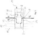
- FIG. 1 The slide chair 10 is fixedly connected to the base plate 12 and arranged such that the slide chair plate 14, in a manner known per se, a stock rail 100.
- the slide chair plate 14 has a base plate 12 and a slide chair plate 14 arranged above it a tongue switch is able to hold.
- the base plate 12 is fixed or attachable to a rail tie 50.
- a support means 21 of the slide chair 10 is intended to receive and support a tensioning device such as a clamping bracket.
- the slide chair can be considered part of a rail switch.
- One of the stock rail 100 associated tongue rail 102 of the rail switch is mounted relative to the stock rail 100 movable on the Gleitstuhlplatte 14.
- the base plate 12 of the slide chair 10 is formed in this example as an electric heating cable electrical heater 20 in a heating receptacle 18, whose course is shown in dashed lines within the slide chair 10.
- the heating receptacle 18 has a first input opening 22, which allows the heating cable 20 to be guided into the base plate 12. Further, a second opening 24 is provided, from which the heating cable 20 is led out of the base plate 12.
- the heating cable 20 is embedded in the heater receptacle 18 and essentially describes a U-shaped arc.
- the heating cable 20 may be guided to one or more other sliding chairs. At the heating cable 20 is applied a potential difference V1-V2, so that through the heating cable, an electric current can flow, which is converted in the heating cable by one or more heating elements into heat.
- This heat is transferred via an inner wall of the heating receptacle to the base plate 12 and to this heat-conducting connected components such as the Gleitstuhlplatte 14abei. It can be provided that a sheath of the heating cable 20 is formed within the base plate 12 at least partially thermally conductive, while outside the Base plate 12 is formed heat-insulating. Thus, heat losses outside of the slide chair 10 are minimized. However, it may be sufficient to design the heating device and / or the heating cable in such a way that its line resistance between sliding chairs and / or outside a sliding chair is low, so that there is no appreciable conversion of electrical energy into heat.
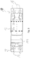
- FIG. 2 shows a cross-sectional view of a mounted slide chair 10.
- the rail holding device 25 is arranged to hold the stock rail 100 on the side facing away from the tongue rail 102 side.
- the tongue rail 102 is movably disposed on the slide chair 10 as shown, and is capable of sliding on the slide chair plate 14 in particular.
- the Gleitstuhlplatte 14 is arranged such that it can clamp the stock rail 100 on the rail holding device 25 opposite side and in particular is able to secure mutual movements.
- a heating cable 20 is laid, which emerges from the outlet opening 24.
- the heating cable 20 in this example has an electrically conductive heating core 30 and an electrically insulating, heat-conducting jacket 32. It can be provided that a region of the heating cable guided outside the slide chair 10 is surrounded by an electrically insulating and heat-insulating jacket.
- a formed on the inner wall of the heater receptacle electrical insulating, but heat-conducting casing is arranged. It can be provided that the heating cable is formed within the casing without its own casing. Generally, one or more heating elements may be in direct heat conducting Contact or via an intermediate layer such as a thermal compound in indirect heat-transmitting contact with the casing stand. A voltage V1 is applied to the end of the heating cable 20 shown.
- FIG. 3 shows a view of the slide chair 10 from above.
- the rail holding device 25 for fixing a stock rail 100 together with mounting holes 16 can be seen here.
- two parallel heating cables 20a and 20b are provided, which are guided in corresponding heating receptacles of the base plate 12.
- one or more heaters, heating cables or heating cables may be routed in respective heater receptacles in any suitable manner, such as meandering, parallel, spiral, etc., to produce a desired heating profile.
- FIG. 4 shows a view of a slide chair 10 from below.
- the heater receptacle 18 is formed and extends substantially U-shaped between the openings 22, 24.
- a substantially oval opening 28 is further formed, through which a clamping device can be seen.
- a tensioning device can be arranged in the support device 21 between the base plate 12 and not to be recognized Gleitstuhlplatte 14.
- the opening 28 serves to receive the tensioning device and allow access to the tensioning device.
- a structural relief of the base plate 12 in the region of the clamping device can take place via the opening 28.
- the heating cable 18 is received in the heater receptacle 18 and is in heat-conducting contact with this, such as a thermal paste.
- the heater receptacle has an open cross-sectional profile. In particular, the profile is open at the bottom, so that the heating cable 20 can be embedded from below into the heating receptacle 18.
- FIG. 5 shows a cross-sectional view of a slide chair 10 from behind.
- the cross section is along the line AA of FIG. 4 taken.
- There is a support device opening 29 can be seen, which allows access to the receiving area between Gleitstuhlplatte 14 and base plate 12. Good to see the heater core 30 and the sheath 32 that surrounds him.
- the heater receptacle 18 is guided within the base plate 12 so as to provide structural integrity the base plate 12 and the attachment of the slide chair 10 is not affected at a threshold or underlay.
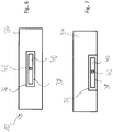
- FIG. 6 shows the arrangement of an electric heater in a component 34 of a slide chair 10, which may be in particular a base plate or a Gleitstuhlplatte.
- the arrangement in a base plate may be advantageous for reasons of stability.
- a heating receptacle 36 is formed, in which a casing 38 is received.
- the casing 38 is electrically insulating, but good heat conducting.
- a heater 40 is received in the casing.
- the heating device 40 has a radiator, which is in heat-conducting contact with the casing 38. Further, the heater 40 has a contact 42, which serves for the supply of electrical energy.
- the radiator may be configured as a heating element and / or be in heat-conducting contact with one or more heating elements, which convert electrical current into heat when supplied with electrical energy via the contact 42, which is discharged via the radiator to the component 34 of the sliding chair 10.
- the radiator is designed such that it rests with its main surfaces and / or at least one side flat against the casing 38.
- a bore or guide can be provided, through which a wiring for contacting 42 can be guided.
- the heater receptacle 36 is substantially completely received in the component 34 so that the sides of its wall are formed by the component 34.
- the heater 40 may be molded into the component 34.
- FIG. 7 shows a variant of an arrangement of a heater 40 in a component 34 of a slide chair 10, which the in FIG. 6 similar arrangement shown.
- the heater receptacle 36 is formed in the component 34 such that it has a downwardly open cross-sectional profile.
- a lower side of the heating receptacle 36 is not closed by a wall part formed by the component 34.
- the casing 38 is accessible to the outside and can rest approximately on a base of the sliding chair.
- the externally accessible part of the casing can be designed to be heat-insulating.
- This variant makes it possible to retrofit the heater 40 and / or to wait. It can be provided that between the shuttering 38 and the wall of the heater receptacle 36 and / or the shuttering 38 and the heater 40, in particular the radiator, a thermal paste is arranged.
Landscapes
- Engineering & Computer Science (AREA)
- Mechanical Engineering (AREA)
- Architecture (AREA)
- Civil Engineering (AREA)
- Structural Engineering (AREA)
- Chair Legs, Seat Parts, And Backrests (AREA)
- Slide Switches (AREA)
- Resistance Heating (AREA)
Description
- Die vorliegende Erfindung betrifft einen Gleitstuhl für eine Schienenweiche, eine Schienenweiche mit mindestens einem derartigen Gleitstuhl sowie eine Weichenheizung für eine Schienenweiche.
- Schieneneinrichtungen für Schienenfahrzeuge sind in besonderem Maße der Witterung ausgesetzt. Insbesondere Schieneneinrichtungen mit beweglichen Teilen wie Schienenweichen können dabei in ihrer Funktionsfähigkeit insbesondere bei Kälte und/oder Eis und Schnee eingeschränkt sein. Derartige Einschränkungen können zu erheblichen Störungen für den Schienenverkehr bis hin zum Ausfall von Zugverbindungen führen. Daher werden in der Regel insbesondere Schienenweichen mit Heizeinrichtungen ausgestattet, um sie bei schlechtem Wetter beheizen zu können. Aufgrund der Komplexität im Aufbau und der Vielzahl unterschiedlichen Komponenten einer Schienenweiche ist dabei auf eine geeignete Anordnung von Heizkomponenten zu achten, um einen gewünschten Heizerfolg erreichen zu können.
- Es ist bereits eine Weichenbeheizung bekannt, bei der ein elektrisches Heizelement am Schienenfuß der Backenschiene an der Innenseite des Stegs angebracht ist. Zusätzlich sind in Ausnehmungen der Gleitstuhlplatte verlaufende Heizstäbe vorgesehen (
DE-A-2102929 ). - Weiterhin ist ein Lager für eine Weiche bekannt, bei dem in einer unter der Weiche angebrachten Bodenplatte eine elektrische Heizeinrichtung untergebracht ist (
FR-A-1049261 - Eine Aufgabe der vorliegenden Erfindung besteht darin, einen Gleitstuhl einer Schienenweiche derart auszugestalten, dass eine kompakte und effiziente Heizung von Komponenten der Schienenweiche möglich ist.
- Diese Aufgabe wird durch einen Gleitstuhl, eine Schienenweiche und eine Weichenheizung gemäß den unabhängigen Ansprüchen gelöst.
- Vorteilhafte Ausgestaltungen und Weiterbildungen ergeben sich aus den abhängigen Ansprüchen.
- Es wird ein Gleitstuhl für eine Schienenweiche beschrieben. Der Gleitstuhl umfasst eine Grundplatte, vermittels welcher der Gleitstuhl festlegbar ist, sowie eine Gleitstuhlplatte, welche mit der Grundplatte fest verbunden ist oder verbindbar ist. Der Gleitstuhl weist eine Heizungsaufnahme zum Aufnehmen mindestens einer elektrischen Heizeinrichtung auf. Somit kann der Gleitstuhl derart ausgebildet sein, dass er einerseits seine normale Funktion als Gleitstuhl erfüllt und andererseits als Teil einer Heizung für eine Weiche wirken kann. Die Heizungsaufnahme kann in einer Komponente des Gleitstuhls ausgebildet sein, etwa der Grundplatte und/oder der Gleitstuhlplatte und/oder einer Befestigungseinrichtung, über welche die Gleitstuhlplatte an der Grundplatte befestigt oder befestigbar ist. Eine Heizungsaufnahme kann eine Wandung aufweisen, die durch den Gleitstuhl gebildet sein kann, insbesondere durch die Grundplatte und/oder Gleitstuhlplatte. Eine Wandung der Heizungsaufnahme kann insbesondere eine Innenwandung sein, welche die im Gleitstuhl vorgesehene Heizungsaufnahme begrenzt. Allgemein kann eine Heizungsaufnahme als ein Hohlraum ausgebildet sein, in welchem die elektrische Heizeinrichtung ganz oder teilweise aufgenommen oder aufnehmbar ist. Die Heizungsaufnahme kann dazu ausgebildet und/oder dimensioniert sein, die Heizeinrichtung aufzunehmen, insbesondere eine Heizleitung und/oder ein Heizkabel und/oder einen Heizkörper. Es kann vorgesehen sein, dass die Heizungsaufnahme dazu ausgebildet und/oder dimensioniert ist, die Heizeinrichtung derart aufzunehmen, dass sie in wärmeübertragendem Kontakt mit einer Innenwandung der Heizungsaufnahme steht. Eine Innenwandung kann einstückig und/oder stoffschlüssig mit derjenigen Komponente des Gleitstuhls ausgebildet sein, in welcher sie angeordnet ist, insbesondere einer Grundplatte und/oder einer Gleitstuhlplatte. An mindestens einer Seite der Heizungsaufnahme kann eine Öffnung vorgesehen sein, welche durch eine externe Seitenwandung geschlossen oder schließbar sein kann, etwa einer Platte oder einer Fläche oder Unterlage, auf welcher der Gleitstuhl angebracht ist und/oder an welcher der Gleitstuhl befestigt oder befestigbar ist. Eine entsprechende Platte kann lösbar an dem Gleitstuhl angebracht oder anbringbar sein, insbesondere der Grundplatte und/oder der Gleitstuhlplatte, etwa durch eine geeignete Verschraubung oder eine Klemmeinrichtung. Eine entsprechende Unterlage oder Fläche kann beispielsweise durch einen Weichenuntergrund wie eine Schwelle bereitgestellt sein. Die Heizungsaufnahme kann zur Wärmeübertragung von der elektrischen Heizeinrichtung an den Gleitstuhl vorgesehen sein, insbesondere an diejenige Komponente, in welcher sie aufgenommen oder aufnehmbar ist, etwa an die Grundplatte und/oder die Gleitstuhlplatte. Die elektrische Heizeinrichtung kann teilweise oder ganz in der Heizungsaufnahme aufgenommen oder aufnehmbar sein. Eine elektrische Heizeinrichtung kann allgemein eine Heizeinrichtung sein, die dazu ausgebildet ist, elektrischen Strom in Heizwärme umzuwandeln. Die elektrische Heizeinrichtung kann durch einen Wechselstrom betreibbar sein. Ein solcher Wechselstrom kann etwa im Eisenbahnbereich bereitgestellt sein, und beispielsweise eine Frequenz von 50Hz aufweisen, oder eine Frequenz von 16 2/3Hz, etwa als Fahrleitungsstrom. Alternativ oder zusätzlich kann die Heizeinrichtung durch einen Gleichstrom betreibbar zu sein. Ein solcher Gleichstrom kann etwa eine Spannung von 660V aufweisen. Gleichstrom kann insbesondere im Straßenbahnbereich eingesetzt sein. Es kann vorgesehen sein, dass eine elektrische Heizeinrichtung dazu ausgebildet ist, an eine elektrische Energieversorgung angeschlossen oder anschließbar zu sein, etwa an eine elektrische Spannungsversorgung und/oder Stromversorgung. Dazu kann etwa eine geeigneten Kontaktierung und/oder eine elektrische Leitungsanordnung und/oder Verkabelung vorgesehen sein. Die elektrische Energieversorgung kann einen Wechselstrom und/oder Gleichstrom zum Betreiben der Heizeinrichtung bereitstellen. Eine elektrische Heizeinrichtung kann ein oder mehrere Heizelemente umfassen, etwa Heizwiderstände, die parallel und/oder seriell geschaltet sein können. Ein solcher Heizwiderstand kann beispielsweise als Spuleneinrichtung oder Induktivitätund/oder als geeignetes metallisches Element ausgebildet sein oder ein solches umfassen. Alternativ oder zusätzlich kann eine derartige Heizeinrichtung ein oder mehrere als Keramikelemente und/oder Halbleiterelemente ausgebildete Heizelemente aufweisen. Derartige Heizelemente können zur Umwandlung eines elektrischen Stroms in Heizwärme ausgebildet sein und etwa als PTC-Heizelemente ausgebildet sein. Die Heizelementekönnen parallel und/oder seriell geschaltet sein. Es ist vorstellbar, dass die Heizungsaufnahme, insbesondere eine Wandung der Heizungsaufnahme wie eine Innenwandung, und die elektrische Heizeinrichtung, etwa ein oder mehrere Heizelemente und/oder eine Heizkörper, in wärmeleitendem Kontakt miteinander stehen, etwa in direktem und/oder indirektem wärmeleitendem Kontakt. Ein indirekter wärmeleitender Kontakt kann über mindestens eine zwischen der elektrischen Heizeinrichtung und der Heizungsaufnahme und/oder einer Wandung der Heizungsaufnahme angeordnete gut wärmeleitende Zwischenschicht erfolgen. Eine derartige Zwischenschicht kann etwa eine Ummantelung der elektrischen Heizeinrichtung und/oder eine Verschalung der Heizungsaufnahme und/oder eine Wärmeleitpaste umfassen oder als solche ausgebildet sein. Es ist vorstellbar, dass die Heizeinrichtung und gegebenenfalls ihr zugeordnete elektrische Elemente wie Versorgungskabel gegenüber dem Gleitstuhl und/oder der Heizungsaufnahme elektrisch isoliert sind, insbesondere gegenüber einer Wandung der Heizungsaufnahme. Beispielsweise können eine Ummantelung der elektrischen Heizeinrichtung und/oder eine Verschalung der Heizungsaufnahme aus einem elektrisch isolierenden Material ausgebildet sein, welches gut wärmeleitfähig sein kann. Somit kann vermieden werden, dass ein elektrischer Strom von der Heizeinrichtung in den Gleitstuhl strömt. Eine Ummantelung und/oder Verschalung kann jeweils eine Schicht oder mehrere Schichten umfassen, die aus unterschiedlichen Materialien ausgebildet sein können. Dabei kann mindestens eine Schicht elektrisch isolierend sein. Es ist vorstellbar, dass eine solche Schicht gut wärmeleitend ist. Bei einer Variante kann vorgesehen sein, dass Teile einer Heizeinrichtung, die zur Positionierung außerhalb eines zu erwärmenden Bereichs vorgesehen sind, eine andersartige Ummantelung aufweisen als Teile einer Heizeinrichtung, die für einen wärmeübertragenden Kontakt mit dem Gleitstuhl vorgesehen sind. Etwa kann eine Ummantelung, die ein Verbindungsstück und/oder eine Verbindungsleitung zwischen zwei Heizeinrichtungen und/oder zwei Gleitstühlen umgibt, wärmeisolierend ausgebildet sein. Es ist auch vorstellbar, dass Abschnitte oder Komponenten der Heizeinrichtung oder Verbindungsleitungen zur Heizeinrichtung innerhalb bestimmter Bereiche eines Gleitstuhls eine wärmeisolierende Ummantelung aufweisen und/oder von einer solchen umgeben sind. Alternativ oder zusätzlich kann eine in einer Heizungsaufnahme angeordnete Verschalung insbesondere an mindestens einer offenen Seiten und/oder mindestens einer Seite, die nicht für einen Kontakt mit dem Gleitstuhl und/oder der Grundplatte und/oder der Gleitstuhlplatte vorgesehen sind, zumindest teilweise wärmeisolierend ausgebildet sein. Eine solche Seite kann beispielsweise einer Bodenseite des Gleitstuhls entsprechen, welche zur Lagerung auf einer Unterlage wie einer Schienenschwelle vorgesehen ist.
- Eine Heizeinrichtung kann mindestens einen Heizkörper umfassen. Ein Heizkörper kann als Wärmeübertrager ausgebildet sein, welcher es vermag, Wärme von einem oder mehreren Heizelementen zu übertragen, insbesondere an eine Wandung der Heizungsaufnahme. Es ist vorstellbar, dass ein Heizkörper als Heizelement ausgebildet ist. Ein Heizkörper kann eine oder mehrere Heizflächen aufweisen, die in wärmeleitenden und/oder kraftschlüssigen und/oder formschlüssigen Kontakt mit einer oder mehreren Flächen einer Innenwandung der Heizungsaufnahme stehen oder bringbar sein können, entweder direkt oder indirekt durch Vermittlung einer oder mehrerer Zwischenschichten. Die Grundplatte kann an einer geeigneten Bodeneinrichtung oder Unterlage der Schienenweiche, insbesondere einer Schwelle, oder an einem anderen erdfesten Bezugspunkt festlegbar sein. Das Festlegen des Gleitstuhls kann insbesondere bedeuten, dass die Grundplatte mit Bezug zur Erde und/oder zur Unterlage verankert und/oder an einer geeigneten Festlegungsvorrichtung befestigt ist, etwa durch Verschraubungen, Einbetonieren, Nägel oder eine andere Befestigungsvorrichtung oder Verankerung. Eine Gleitstuhlplatte kann dazu vorgesehen sein, eine Schiene der Schienenweiche, insbesondere eine Backenweiche, gegen eine Verschiebung festzulegen. Dazu kann die Gleitstuhlplatte fest mit der Grundplatte verbunden oder verbindbar sein, beispielsweise vermittels einer Verbindungseinrichtung, welche etwa eine geeignete Verschraubung und/oder Verschweißung umfassen kann oder als solche ausgebildet sein kann. Es ist vorstellbar, dass eine Gleitstuhlplatte ferner dazu vorgesehen ist, eine Zungenweiche bewegbar zu lagern. Die Grundplatte und/oder die Gleitstuhlplatte können allgemein aus einem metallischen Material hergestellt sein, etwa aus einem Stahl oder Aluminium oder einer Legierung. Es ist vorstellbar, dass Grundplatte und/oder Gleitstuhlplatte und/oder Gleitstuhl aus einem Gussmaterial wie einem Gussmetall hergestellt sind. Eine Heizungsaufnahme kann direkt im Gleitstuhl, insbesondere in der Grundplatte und/oder Gleitstuhlplatte ausgebildet sein, etwa in Form einer oder mehrerer Bohrungen. Bei einer Variante können eineHeizungseinrichtung und gegebenenfalls eine Ummantelung und/oder eine Verschalungim Gleitstuhl, insbesondere in der Grundplatte, aufgenommen sein, etwa indem sie in den Gleitstuhl und/oder Grundplatte eingegossen sind oder beim Montieren des Gleitstuhl oder der Komponente des Gleitstuhls eingebaut werden. Die Heizungseinrichtung kann eine geeignete Kontaktierung aufweisen, die eine Versorgung mit elektrischer Energie und/oder mit einer elektrischen Spannung und/oder einem elektrischen Strom erlaubt. Eine solche Kontaktierung kann zur Außenseite des Gleitstuhls und/oder aus dem Gleitstuhl heraus geführt oder führbar sein, um einen leichten Zugang zum Anschließen der elektrischen Heizeinrichtung an eine Spannungsversorgung zu ermöglichen. Es ist vorstellbar, dass in einer Grundplatte oder Gleitstuhlplatte eine entsprechende Führung vorgesehen ist, die es vermag, eine Verkabelung oder Leitereinrichtung zur Kontaktierung aufzunehmen. Allgemein kann im Rahmen dieser Beschreibung eine Schienenweiche eine Zungenweiche sein. Eine Schienenweiche kann zumindest ein Schienenpaar aus Backenschiene und Zungenschiene aufweisen. Ein Gleitstuhl kann dazu vorgesehen sein, eine Backenschiene auf ihrer der Zungenschiene zugewandten Seite festzulegen. Es ist vorstellbar, dass eine Zungenweiche sich auf dem Gleitstuhl zu verschieben vermag. Insbesondere kann vorgesehen sein, dass die Gleitstuhlplatte dazu ausgebildet ist, die Zungenweiche verschiebbar zu lagern. Die Gleitstuhlplatte kann oberhalb der Grundplatte an dieser direkt oder indirekt befestigt sein. Insbesondere kann vorgesehen sein, dass sich die Gleitstuhlplatte im Wesentlichen nicht relativ zur Grundplatte zu bewegen vermag und/oder relativ zur Grundplatte ortsfest befestigt oder befestigbar ist. Gleitstuhlplatte und Grundplatte können jeweils einstückig ausgebildet sein. Es ist allgemein vorstellbar, dass die Gleitstuhlplatte formschlüssig an der Grundplatte angebracht oder anbringbar ist, oder dass die Gleitstuhlplatte materialschlüssig mit der Grundplatte ausgebildet ist. Die Heizungsaufnahme kann in die Grundplatte und/oder Gleitstuhlplatte gegossen und/oder gefräst und/oder gebohrt sein. Es ist vorstellbar, dass die Heizungsaufnahme an einer Verbindungsstelle zwischen der Grundplatte und der Gleitstuhlplatte ausgebildet ist. Dabei kann die Heizungsaufnahme zum Teil in der Grundplatte und zu einem anderen Teil in der Gleitstuhlplatte ausgebildet sein.Die Heizungsaufnahme kann eine oder mehrere Öffnungen aufweisen, welche einen Zugang zur Heizungsaufnahme von außen bereitstellt und/oder ein Einführen oder Einlegen einer Heizeinrichtung in die Heizungsaufnahme erlaubt, so dass die Heizeinrichtung durch die Öffnung von außen kontaktierbar ist und/oder nach außen führbar oder geführt ist. Es kann vorgesehen sein, dass die Heizungsaufnahme zwischen zwei Öffnungen, insbesondere zwischen zwei auf gegenüberliegenden Seiten des Gleitstuhls angeordneten Öffnungen, keine gerade Linie beschreibt, sondern in einer gebogenen oder abgewinkelten Form ausgebildet ist. Dabei können mehrere Bögen und/oder Abwinklungen vorgesehen sein. Es ist insbesondere vorstellbar, dass die elektrische Heizeinrichtung als Heizkabel ausgebildet ist, welches innerhalb der Heizungsaufnahme geführt oder führbar ist.Die Heizungsaufnahme kann ein in dem Gleitstuhl aufgenommenes oder eingegossenes Rohr umfassen, in welchem etwa ein Kabel aufgenommen oder aufnehmbar sein kann.Insbesondere kann ein Heizkabel in wärmeleitenden Kontakt mit einer Innenwand eines solchen Rohres bringbar sein oder stehen. Ein Heizkabel kann über eine Öffnung in dem Gleitstuhl, insbesondere in der Grundplatte und/oder Gleitstuhlplatte, und/oder über mehrere derartige Öffnungen aus dem Gleitstuhl, insbesondere der Grundplatte und/oder der Gleitstuhlplatte,herausgeführt oder herausführbar sein.Damit kann etwa eine außerhalb des Gleitstuhls angeordnete oder anordenbare Anschlussmöglichkeit bereitgestellt sein. Allgemein kann eine Heizeinrichtung auf geeignete Art in der Heizungsaufnahme und/oder an dem Gleitstuhl und/oder an der Grundplatte und/oder der Gleitstuhlplatte befestigt oder befestigbar sein, etwa durch Verschrauben und/oder Verkleben und/oder Verklemmen und/oder Verschweißen und/oder Verlöten und/oder Vergießen oder Eingießen. Die Form und Dimensionierung der Heizungsaufnahme kann unter Berücksichtigung einer gewünschten Wärmeübertragung durch die Heizungsaufnahme und/oder struktureller Erfordernisse des Gleitstuhls bestimmt sein. Ein wärmeübertragender Kontakt kann ein wärmeleitender Kontakt sein. Es ist vorstellbar, dass ein wärmeleitender Kontakt zwischen zwei Komponenten, etwa einer Heizeinrichtung und dem Gleitstuhl, insbesondere der Grundplatte und/oder der Gleitstuhlplatte, durch direkten Kontakt der Komponenten bereitgestellt oder bereitstellbar ist. Alternativ oder zusätzlich kann ein wärmeleitender Kontakt zwischen zwei Komponenten über ein oder mehrere zwischen diesen Komponenten angeordnete Wärmeleitelemente bereitgestellt oder bereitstellbar sein. Ein Wärmeleitelement kann dabei gute Wärmeleiteigenschaften aufweisen und etwa eine Wärmeleitpaste und/oder ein metallisches Element wie eine Metallschicht oder eine Folie umfassen. Es kann beispielsweise vorgesehen sein, dass zwischen einer Heizeinrichtung, etwa einem Heizkabel, und dem Gleitstuhl, insbesondere der Grundplatte und/oder der Gleitstuhlplatte und/oder einer Innenwandung der Heizungsaufnahme, zumindest stellenweise eine Wärmeleitpaste angeordnet oder anordenbar ist. Die Wärmeleitpaste kann auf einer gut wärmeleitenden elektrischen Isolierung der Heizeinrichtung angebracht sein. Allgemein kann es zweckmäßig sein, wenn für einen wärmeleitenden Kontakt vorgesehene Komponenten selbst gute Wärmeleitungseigenschaften aufweisen und beispielsweise aus metallischen Materialien bestehen und/oder solche umfassen. Dabei können unterschiedliche Komponenten unterschiedliche Materialien aufweisen. Bei einer Variante umfasst der Gleitstuhl eine Schienenhalteeinrichtung. Die Schienenhalteeinrichtung kann dazu ausgebildet sein, eine Schiene, insbesondere eine Backenschiene, an dem Gleitstuhl zu befestigen. Die Schiene kann über die Schienenhalteeinrichtung an dem Gleitstuhl befestigt oder befestigbar sein. Es ist vorstellbar, dass die Schienenhalteeinrichtung derart angeordnet ist, dass eine an ihr befestigte Schiene zwischen der Schienenhalteinrichtung und der Gleitstuhlplatte aufgenommen oder aufnehmbar ist. Insbesondere kann die Schiene durch die Gleitstuhlplatte auf ihrer der Schienenhalteeinrichtung gegenüberliegenden Seite eingeklemmt oder einklemmbar sein. Die Schienenhalteeinrichtung kann eine Verschraubung und/oder eine Bolzeneinrichtung aufweisen, vermittels welcher die Schiene befestigt oder befestigbar ist. Zwischen Grundplatte und Gleitstuhlplatte kann ein Aufnahmebereich vorgesehen sein, welcher es vermag, eine Spanneinrichtung aufzunehmen. Eine solche Spanneinrichtung kann dazu vorgesehen sein, die Befestigungseigenschaften der Gleitstuhlplatte auch bei Belastungen etwa durch einen den Gleitstuhl überfahrenden Zug positiv zu beeinflussen. Zweckmäßigerweise kann die Heizungsaufnahme derart angeordnet sein, dass sie die Wirkungsweise der Spanneinrichtung nicht beeinträchtigt.
- Der Gleitstuhl ist derart ausgebildet, dass die mindestens eine elektrische Heizeinrichtung in der Grundplatte und der Gleitstuhlplatte aufgenommen ist. Dazu kann die Heizungsaufnahme entsprechend in der Grundplatte und/oder in der Gleitstuhlplatte ausgebildet sein. Insbesondere die Gleitstuhlplatte ist stabil genug ausgebildet, um einen Hohlraum für die Heizungsaufnahme bieten zu können ohne ihre Struktur nennenswert zu schwächen. Es kann vorgesehen sein, dass eine im Wesentlichen flächig ausgebildete Heizeinrichtung derart in der Heizaufnahme der Grundplatte und/oder Gleitstuhlplatte aufgenommen ist, dass sie mit ihren Hauptflächen und/oder Seitenflächen im Wesentlichen kraftschlüssig mit der jeweiligen Platte verbunden ist und/oder kraftschlüssig an der jeweiligen Platte anliegt. Dies kann insbesondere für eine Heizeinrichtung vorgesehen sein, die innerhalb der Platte aufgenommen ist, etwa indem sie eingegossen ist. Somit wird die Stabilität der Platte durch den Hohlraum nicht beeinträchtigt.
- Insbesondere kann vorgesehen sein, dass die Grundplatte eine Heizungsaufnahme für die elektrische Heizeinrichtung aufweist.Somit kann die Heizungsaufnahme in einer stabilen und auf dem Erdboden gelagerten Komponente des Gleitstuhls ausgebildet sein. Dabei kann die Heizungsaufnahme ein offenes Profil aufweisen. Insbesondere kann die Heizungsaufnahme derart ausgebildet sein, dass mindestens eine Seite, insbesondere eine Bodenseite, einer Wandung der Heizungsaufnahme ganz oder teilweise offen ist. Eine solche offene Seite kann durch eine externe Begrenzung wie eine Unterlage oder Standfläche des Gleitstuhls und/oder eine an dem Gleitstuhl anbringbare separat ausgebildete Platte verschließbar oder verschlossen sein. Eine Seite einer Wandung kann insbesondere als offen angesehen werden, wenn ihre Begrenzung nicht einstückig und/oder stoffschlüssig mit anderen Flächen einer Innenwandung der Heizungsaufnahme ausgebildet ist. Das Profil kann allgemein ein Querschnittsprofil sein, dessen Flächennormale parallel zu einer Stellfläche und/oder dem Erdboden und/oder der Längserstreckung der Grundplatte gerichtet ist. Dabei können im Gleitstuhl Bohrungen oder Durchgänge zur Heizungsaufnahme vorgesehen sein, um einen Zugang und/oder ein Kontaktieren und/oder ein Versorgen mit elektrischer Energie der Heizeinrichtung auch von anderen Seiten zu ermöglichen.
- Die Heizungsaufnahme kann ein geschlossenes Profil aufweisen. Dabei kann ein Profil allgemein ein oben beschriebenes Querschnittsprofil sein. Somit kann die Heizeinrichtung durch den Gleitstuhl gehalten und/oder in den Gleitstuhl eingegossen sein. Im Gleitstuhl können Bohrungen oder Durchgänge zur Heizungsaufnahme vorgesehen sein, um einen Zugang und/oder ein Kontaktierenund/oder ein Versorgen mit elektrischer Energie der Heizeinrichtung zu ermöglichen.
- Die elektrische Heizeinrichtung umfasst mindestens eine Heizleitung. Es ist vorstellbar, dass eine Heizleitung als Heizkabel und/oder als Teil eines Heizkabels ausgebildet ist. Ein Heizkabel kann biegbar und/oder elastisch ausgebildet sein. Es ist vorstellbar, dass ein Heizkabel eine Ummantelung aufweist, welche eine oder mehrere Heizleitungen und/oder Heizeinrichtungen umgibt. Eine Heizeinrichtung oder Heizleitung kann dabei insbesondere mindestens eine Spuleund/oder einen geeigneten Heizwiderstand und/oder ein keramisches Heizelement umfassen. Eine Ummantelung kann ein gut wärmeleitendes Material und/oder ein elektrisch isolierendes Material umfassen. Es ist vorstellbar, dass die Ummantelung mehrere Schichten aus solchen Materialien aufweist und/oder dass mindestens eine Schicht sowohl gut wärmeleitend als auch elektrisch isolierend ausgebildet ist.
- Es ist vorstellbar, dass die mindestens eine Heizleitung in mindestens einem Bogen geführt oder führbar ist. Damit kann eine bessere Flächenheizung auch durch eine länglich ausgerichtete Heizeinrichtung wie eine Heizleitung erreicht werden.
- Bei einer Weiterbildung kann die elektrische Heizeinrichtung mindestens einen Heizkörper umfassen, der im Gleitstuhl aufgenommen ist. Der Heizkörper kann ein gut wärmeleitendes Material aufweisen. Es ist vorstellbar, dass der Heizkörper aus einem metallischen Material hergestellt ist. Der Heizkörper kann als Heizelement ausgebildet sein und/oder mit einem oder mehreren Heizelement in wärmeleitendem Kontakt stehen.
- Die vorliegende Erfindung betrifft außerdem eine Weichenheizung, welche dazu ausgebildet ist, einen elektrischen Heizstrom durch mindestens eine in einem hierin beschriebenen Gleitstuhl aufgenommene elektrische Heizeinrichtung strömen zu lassen. Die Weichenheizung kann eine elektrische Energieversorgung etwa mit ein oder mehreren Strom- und/oder Spannungsquellen aufweisen, die an die Heizeinrichtungen angeschlossen oder anschließbar sein kann. Die Weichenheizung kann mehrere Heizeinrichtungen aufweisen, die mehreren Gleitstühlen zugeordnet oder zuordenbar sein können. Die Heizeinrichtungen können durch geeignete Stromleitungen und/oder Verbindungskabel miteinander und/oder mit einer elektrischen Energieversorgung verbunden oder verbindbar sein.
- Ferner kann eine Schienenweiche mit mindestens einem hierin beschriebenen Gleitstuhl und/oder einer hierin beschriebenen Weichenheizung vorgesehen sein. Die Schienenweiche kann insbesondere eine Zungenweiche sein und entsprechend Backenschienen und Zungenschienen aufweisen. Es können mehrere Gleitstühle und/oder diesen zugeordnete elektrische Heizeinrichtungen vorgesehen sein, welche seriell und/oder parallel zueinander geschaltet und/oder in Gruppen oder einzeln geschaltet sein können. Die Heizeinrichtungen können entsprechend mit einer elektrischen Energieversorgung verbunden oder verbindbar sein.
- In folgendem werden Ausführungsformen der Erfindung beispielhaft anhand der beiliegenden Figuren beschrieben.
- Es zeigen:
- Fig. 1
- schematisch eine Ansicht eines Gleitstuhls,
- Fig. 2
- eine Seitenansicht eines Gleitstuhls einer Schienenweiche,
- Fig. 3
- eine Draufsicht eines Gleitstuhls,
- Fig. 4
- eine Sicht auf einen Gleitstuhl von unten,
- Fig. 5
- eine Querschnittsansicht eines Gleitstuhls,
- Fig. 6
- schematisch eine Querschnittsansicht einer Platte eines Gleitstuhls, und
- Fig. 7
- schematisch eine Querschnittsansicht einer Platte einer weiteren Variante eines Gleitstuhls.
-
Figur 1 zeigt schematisch eine Draufsicht eines Gleitstuhls 10. Der Gleitstuhl 10 umfasst eine Grundplatte 12 und eine darüber angeordnete Gleitstuhlplatte 14. Die Gleitstuhlplatte 14 ist fest mit der Grundplatte 12 verbunden und derart angeordnet, dass die Gleitstuhlplatte 14 auf an sich bekannte Art und Weise eine Backenschiene 100 einer Zungenweiche zu halten vermag. Über Befestigungslöcher 16 ist die Grundplatte 12 an einer Schienenschwelle 50 befestigt oder befestigbar. Eine Abstützeinrichtung 21des Gleitstuhls 10 ist dazu vorgesehen, eine Spanneinrichtung wie einen Spannbügel aufzunehmen und abzustützen. Der Gleitstuhl kann als Teil einer Schienenweiche angesehen werden. Eine der Backenschiene 100 zugeordnete Zungenschiene 102 der Schienenweiche ist gegenüber der Backenschiene 100 bewegbar auf der Gleitstuhlplatte 14 gelagert. In der Grundplatte 12 des Gleitstuhls 10 ist in einer Heizungsaufnahme 18 eine in diesem Beispiel als elektrisches Heizkabel ausgebildete elektrische Heizeinrichtung 20 vorgesehen, deren Verlauf innerhalb des Gleitstuhls 10 gestrichelt dargestellt ist. Die Heizungsaufnahme18 weist eine erste Eingangsöffnung 22auf, welche das Führen des Heizkabels 20 in die Grundplatte 12 erlaubt. Ferner ist eine zweite Öffnung 24 vorgesehen, aus welcher das Heizkabel 20 aus der Grundplatte 12 herausgeführt ist. Das Heizkabel 20 ist in der Heizungsaufnahme 18 eingebettet undbeschreibt im Wesentlichen einen u-förmigen Bogen. Das Heizkabel 20 kann zu einem oder mehreren weiteren Gleitstühlen geführt sein. An das Heizkabel 20 ist eine Potentialdifferenz V1-V2 angelegt, so dass durch das Heizkabel ein elektrischer Strom fließen kann, der im Heizkabel durch ein oder mehrere Heizelemente in Wärme umgewandelt wird. Diese Wärme wird über eine Innenwandung der Heizungsaufnahme an die Grundplatte 12 und an mit dieser wärmeleitend verbundenen Komponenten wie der Gleitstuhlplatte 14 übertragen.Dabei kann vorgesehen sein, dass eine Ummantelung des Heizkabels 20 innerhalb der Grundplatte 12 zumindest teilweise wärmeleitend ausgebildet ist, während sie außerhalb der Grundplatte 12 wärmeisolierend ausgebildet ist. Somit werden Wärmeverluste außerhalb des Gleitstuhls 10 minimiert. Es kann allerdings ausreichen, die Heizeinrichtung und/oder des Heizkabels derart auszubilden, dass sein Leitungswiderstand zwischen Gleitstühlen und/oder außerhalb eines Gleitstuhls gering ist, so dass keine nennenswerte Umsetzung elektrischer Energie in Wärme erfolgt. -
Figur 2 zeigt eine Querschnittsansicht eines montierten Gleitstuhls 10. Auf der Grundplatte 12 des Gleitstuhls 10 ist zum einen die Schienenhalteeinrichtung 25 angeordnet, um die Backenschiene 100 auf der von der Zungenschiene 102 abgewandten Seite zu halten. Die Zungenschiene 102 ist wie dargestellt beweglich auf dem Gleitstuhl 10 angeordnet und kann sich insbesondereauf der Gleitstuhlplatte 14 verschieben. Die Gleitstuhlplatte 14 ist derart angeordnet, dass sie die Backenschiene 100 auf der der Schienenhalteeinrichtung 25 gegenüberliegenden Seite einzuklemmen und insbesondere gegenseitliche Bewegungenzu sichern vermag. Innerhalb der Heizungsaufnahme 18 ist ein Heizungskabel 20 verlegt, welches aus der Ausgangsöffnung 24 austritt. Zwischen der Gleitstuhlplatte 14 und der Grundplatte 12 ist ein Aufnahmebereich der Abstützeinrichtung 21 vorgesehen, in welchem eine durch die Abstützeinrichtung 21 abstützbare Spanneinrichtungaufgenommen sein kann. Ferner kann die Grundplatte 10 über ein beispielhaft dargestelltes Befestigungsloch 16 festgelegt oder festlegbar sein. Es versteht sich, dass mehrere Befestigungslöcher vorgesehen sein können. Das Heizkabel 20 in diesem Beispiel weist einen elektrisch leitenden Heizkern 30 sowie eine elektrisch isolierende, wärmeleitende Ummantelung 32 auf. Es kann vorgesehen sein, dass ein außerhalb des Gleitstuhls 10 geführter Bereich des Heizkabels von einer elektrisch isolierenden und wärmeisolierenden Ummantelung umgeben ist. Bei einer Variante kann vorgesehen sein, dass innerhalb der Heizungsaufnahme 18 eine an der Innenwandung der Heizungsaufnahme ausgebildete elektrische isolierende, aber wärmeleitende Verschalung angeordnet ist. Dabei kann vorgesehen sein, dass das Heizkabel innerhalb der Verschalung ohne eigene Ummantelung ausgebildet ist. Allgemein können ein oder mehrere Heizelemente in direktem wärmeleitendem Kontakt oder über eine Zwischenschicht wie etwa einer Wärmeleitpaste in indirektem wärmeübertragendem Kontakt mit der Verschalung stehen. Eine Spannung V1 liegt an dem gezeigten Ende des Heizkabels 20 an. -
Figur 3 zeigt eine Ansicht des Gleitstuhls 10 von oben. Im Gegensatz zur Ansicht der Figur 1 ist hier die Schienenhaltevorrichtung 25 zum Festlegen einer Backenschiene 100 zusammen mit Befestigungslöchern 16 zu erkennen. Ferner sind in diesem Beispiel statt eines u-förmig geführten Heizkabels 20 zwei parallel angeordnete Heizkabel 20a und 20b vorgesehen, die in entsprechenden Heizungsaufnahmen der Grundplatte 12 geführt sind. Allgemein können ein oder mehrere Heizeinrichtungen, Heizkabel oder Heizleitungen in entsprechenden Heizungsaufnahmen auf jede geeignete Art geführt werden, etwa mäanderförmig, parallel, spiralförmig, usw., um ein gewünschtes Erwärmungsprofil zu erzeugen. -
Figur 4 zeigt eine Ansicht eines Gleitstuhls 10 von unten. Es ist zu erkennen, dass in der Grundplatte 12 die Heizungsaufnahme 18 ausgebildet ist und sich im Wesentlichen u-förmig zwischen den Öffnungen 22, 24 erstreckt. In der Grundplatte 12 ist ferner eine im Wesentlichen ovale Öffnung28ausgebildet, durch welche eine Spanneinrichtung zu erkennen ist. Eine solche Spanneinrichtung kann in der Abstützeinrichtung 21 zwischen Grundplatte 12 und nicht zu erkennender Gleitstuhlplatte 14 angeordnet sein. Die Öffnung 28 dient zum Aufnehmen der Spanneinrichtung und kann einen Zugang zur Spanneinrichtungermöglichen. Ferner kann über die Öffnung 28 eine strukturelle Entlastung der Grundplatte 12 im Bereich der Spanneinrichtung erfolgen. Das Heizkabel 18 ist in der Heizungsaufnahme 18 aufgenommen und steht mit diesem in wärmeleitendem Kontakt, etwa über eine Wärmeleitpaste. In dieser Variante ist auch zu erkennen, dass die Heizungsaufnahme ein offenes Querschnittsprofil aufweist. Insbesondere ist das Profil nach unten offen, so dass das Heizkabel 20 von unten in die Heizungsaufnahme 18 eingebettet werden kann. -
Figur 5 zeigt eine Querschnittsansicht eines Gleitstuhls 10 von hinten. Der Querschnitt ist entlang der Linie A-A derFigur 4 genommen. Es ist eine Abstützeinrichtungsöffnung 29 zu erkennen, welche einen Zugang zum Aufnahmebereich zwischen Gleitstuhlplatte 14 und Grundplatte 12 erlaubt. Gut zu erkennen sind der Heizkern 30 und die Ummantelung 32, die ihn umgibt. Wie aus den Zeichnungen allgemein zu erkennen ist, ist die Heizungsaufnahme 18 derart innerhalb der Grundplatte 12 geführt, dass sie die strukturelle Integrität der Grundplatte 12 und die Befestigung des Gleitstuhls 10 an einer Schwelle oder Unterlage nicht beeinträchtigt. -
Figur 6 zeigt die Anordnung einer elektrischen Heizeinrichtung in einer Komponente 34 eines Gleitstuhls 10, die insbesondere eine Grundplatte oder eine Gleitstuhlplatte sein kann. Die Anordnung in einer Grundplatte kann aus Gründen der Stabilität vorteilhaft sein. In der Komponente 34 ist eine Heizungsaufnahme 36 ausgebildet, in welcher eine Verschalung 38 aufgenommen ist. Die Verschalung 38 ist elektrisch isolierend, aber gut wärmeleitend. In der Verschalung ist eine Heizeinrichtung 40 aufgenommen. Die Heizeinrichtung 40 weist einen Heizkörper auf, welcher in wärmeleitendem Kontakt mit der Verschalung 38 steht. Ferner weist die Heizeinrichtung 40 eine Kontaktierung 42 auf, die zur Versorgung mit elektrischer Energie dient. Der Heizkörper kann als Heizelement ausgebildet sein und/oder in wärmeleitendem Kontakt mit einem oder mehreren Heizelementen stehen, die bei Versorgung mit elektrischer Energie über die Kontaktierung 42 elektrischen Strom in Wärme umwandeln, welche über den Heizkörper an die Komponente 34 des Gleitstuhls 10 abgegeben wird. Der Heizkörper ist derart ausgebildet, dass er mit seinen Hauptflächen und/oder mindestens einer Seite flächig an der Verschalung 38 anliegt. In der Komponente 34 kann eine Bohrung oder Führung vorgesehen sein, durch welche eine Verkabelung zur Kontaktierung 42 führbar ist. In diesem Beispiel ist die Heizungsaufnahme 36 im Wesentlichen vollständig in der Komponente 34 aufgenommen, so dass die Seiten ihrer Wandung durch die Komponente 34 gebildet sind. Die Heizeinrichtung 40 kann in die Komponente 34 eingegossen sein. -
Figur 7 zeigt eine Variante einer Anordnung einer Heizeinrichtung 40 in einer Komponente 34 eines Gleitstuhls 10, welche der inFigur 6 gezeigten Anordnung ähnelt. Bei dieser Variante ist die Heizungsaufnahme 36 allerdings derart in der Komponente 34 ausgebildet, dass sie ein nach unten offenes Querschnittprofil aufweist. Insbesondere ist eine Unterseite der Heizungsaufnahme 36 nicht durch einen durch die Komponente 34 gebildeten Wandungsteil geschlossen. Stattdessen ist in diesem Beispiel die Verschalung 38 nach außen zugänglich und kann etwa auf einer Unterlage des Gleitstuhls aufliegen. Der von außen zugängliche Teil der Verschalung kann wärmeisolierend ausgebildet sein. Diese Variante ermöglicht es, die Heizeinrichtung 40 nachträglich zu montieren und/oder zu warten. Es kann vorgesehen sein, dass zwischen Verschalung 38 und der Wandung der Heizungsaufnahme 36 und/oder der Verschalung 38 und der Heizeinrichtung 40, insbesondere dem Heizkörper, eine Wärmeleitpaste angeordnet ist. -
- 10
- Gleitstuhl
- 12
- Grundplatte
- 14
- Gleitstuhlplatte
- 16
- Befestigungslöcher
- 18
- Heizungsaufnahme
- 20
- Heizkabel
- 21
- Abstützeinrichtung
- 22
- Eingangsöffnung
- 24
- Ausgangsöffnung
- 25
- Schienenhalteinrichtung
- 28
- Öffnung
- 29
- Abstützeinrichtungsöffnung
- 30
- Heizkern
- 32
- Ummantelung
- 34
- Gleitstuhlkomponente
- 36
- Heizungsaufnahme
- 38
- Verschalung
- 40
- Heizeinrichtung
- 42
- Kontaktierung
- 50
- Schwelle
- 100
- Backenschiene
- 102
- Zungenschiene
Claims (8)
- Gleitstuhl (10) für eine Schienenweiche, umfassend
eine Grundplatte (12), vermittels welcher der Gleitstuhl (10) festgelegt oder festlegbar ist;
eine Gleitstuhlplatte (14), welche mit der Grundplatte (12) fest verbunden oder verbindbar ist;
mindestens eine elektrische Heizeinrichtung (20,40);
wobei der Gleitstuhl (10) eine Heizungsaufnahme (18, 36) zum Aufnehmen der mindestens einen elektrischen Heizeinrichtung (20, 40) aufweist und wobei die elektrische Heizeinrichtung (20, 40) mindestens eine Heizleitung (20) umfasst, dadurch gekennzeichnet, dass die elektrische Heizeinrichtung (20,40) in der Grundplatte (12) und der Gleitstuhlplatte (14) aufgenommen ist. - Gleitstuhl nach Anspruch 1, dadurch gekennzeichnet, dass die Grundplatte (12) eine Heizungsaufnahme (18, 36) für die elektrische Heizeinrichtung (20, 40) aufweist.
- Gleitstuhl nach Anspruch 2, dadurch gekennzeichnet, dass die Heizungsaufnahme (18, 36) ein offenes Profil aufweist.
- Gleitstuhl nach einem der vorhergehenden Ansprüche, dadurch gekennzeichnet, dass die Heizungsaufnahme (36) ein geschlossenes Profil aufweist.
- Gleitstuhl nach einem der vorhergehenden Ansprüche, dadurch gekennzeichnet, dass die mindestens eine Heizleitung (20) in mindestens einem Bogen geführt oder führbar ist.
- Gleitstuhl nach einem der vorhergehenden Ansprüche, dadurch gekennzeichnet, dass die elektrische Heizeinrichtung (40) mindestens einen Heizkörper umfasst, der im Gleitstuhl (10) aufgenommen ist.
- Weichenheizung für eine Schienenweiche, mit mindestens einem Gleitstuhl (10) nach einem der Ansprüche 1 bis 6, wobei die Weichenheizung dazu ausgebildet ist, einen elektrischen Heizstrom durch die in dem Gleitstuhl (10) aufgenommene elektrische Heizeinrichtung (20, 40) strömen zu lassen.
- Schienenweiche mit mindestens einem Gleitstuhl (10) nach einem der Ansprüche 1 bis 6 oder mindestens einer Weichenheizung nach Anspruch 7.
Priority Applications (1)
| Application Number | Priority Date | Filing Date | Title |
|---|---|---|---|
| PL13193695T PL2735649T3 (pl) | 2012-11-23 | 2013-11-20 | Krzesło ślizgowe dla rozjazdów szynowych |
Applications Claiming Priority (1)
| Application Number | Priority Date | Filing Date | Title |
|---|---|---|---|
| DE102012111357.2A DE102012111357A1 (de) | 2012-11-23 | 2012-11-23 | Gleitstuhl für eine Schienenweiche |
Publications (3)
| Publication Number | Publication Date |
|---|---|
| EP2735649A2 EP2735649A2 (de) | 2014-05-28 |
| EP2735649A3 EP2735649A3 (de) | 2015-05-13 |
| EP2735649B1 true EP2735649B1 (de) | 2018-06-27 |
Family
ID=49674166
Family Applications (1)
| Application Number | Title | Priority Date | Filing Date |
|---|---|---|---|
| EP13193695.7A Not-in-force EP2735649B1 (de) | 2012-11-23 | 2013-11-20 | Gleitstuhl für eine Schienenweiche |
Country Status (4)
| Country | Link |
|---|---|
| EP (1) | EP2735649B1 (de) |
| DE (1) | DE102012111357A1 (de) |
| ES (1) | ES2689030T3 (de) |
| PL (1) | PL2735649T3 (de) |
Families Citing this family (4)
| Publication number | Priority date | Publication date | Assignee | Title |
|---|---|---|---|---|
| FI3026176T4 (fi) † | 2014-11-28 | 2025-07-01 | Vossloh Laeis Gmbh | Vaihde-elin, vaihde ja lämmityslaitteella varustetun vaihde-elimen valmistusmenetelmä |
| PL3141657T3 (pl) * | 2015-09-09 | 2018-10-31 | Track Tec S.A. | Urządzenie do ogrzewania rozjazdu kolejowego |
| DE102020129223B3 (de) | 2020-11-05 | 2022-04-21 | Esa Elektroschaltanlagen Grimma Gmbh | Verfahren und Einrichtung zum Beheizen von Fahrwegelementen |
| US12359377B1 (en) | 2024-04-10 | 2025-07-15 | voestalpine Railway Systems Nortrak LLC | Switch point roller assembly |
Citations (1)
| Publication number | Priority date | Publication date | Assignee | Title |
|---|---|---|---|---|
| WO2013037635A1 (de) * | 2011-09-13 | 2013-03-21 | Triple S-Gmbh | Weichenheizungssystem |
Family Cites Families (6)
| Publication number | Priority date | Publication date | Assignee | Title |
|---|---|---|---|---|
| FR1049261A (fr) * | 1951-01-19 | 1953-12-29 | Signaux Entr Electriques | Coussinet d'aiguilles de chemin de fer à chauffage électrique |
| DE2102929A1 (de) * | 1971-01-22 | 1972-08-03 | Bielefelder Elektrotechnische | Weichenbeheizung |
| DE2113518C3 (de) * | 1971-03-19 | 1975-11-13 | Bielefelder Elektrotechnische Fabrik Hanning & Kahl, 4800 Bielefeld | Heizeinrichtung für Weichen von Rillenschienenbahnen |
| IT8604823A0 (it) * | 1986-05-27 | 1986-05-27 | Plattner Franz | Impianto di riscaldamento per il disgelo di scambi per ferrovia a conduzione del calore tramite liquido caldo. |
| GB2417508B (en) * | 2004-08-24 | 2006-07-12 | Schwihag Gmbh | Fastening device for fixing a stock rail in a set of railway points |
| DE202012103256U1 (de) * | 2012-08-28 | 2013-12-02 | Triple S-Gmbh | Gleitstuhl für eine Schienenweiche |
-
2012
- 2012-11-23 DE DE102012111357.2A patent/DE102012111357A1/de not_active Ceased
-
2013
- 2013-11-20 EP EP13193695.7A patent/EP2735649B1/de not_active Not-in-force
- 2013-11-20 PL PL13193695T patent/PL2735649T3/pl unknown
- 2013-11-20 ES ES13193695.7T patent/ES2689030T3/es active Active
Patent Citations (1)
| Publication number | Priority date | Publication date | Assignee | Title |
|---|---|---|---|---|
| WO2013037635A1 (de) * | 2011-09-13 | 2013-03-21 | Triple S-Gmbh | Weichenheizungssystem |
Also Published As
| Publication number | Publication date |
|---|---|
| DE102012111357A1 (de) | 2014-05-28 |
| PL2735649T3 (pl) | 2018-12-31 |
| EP2735649A2 (de) | 2014-05-28 |
| EP2735649A3 (de) | 2015-05-13 |
| ES2689030T3 (es) | 2018-11-08 |
Similar Documents
| Publication | Publication Date | Title |
|---|---|---|
| EP2792533A2 (de) | Beheizbarer Stromabnehmer zum Herstellen von elektrischem Kontakt zwischen einer stromführenden Leitung und einem Elektrofahrzeug, sowie Heizeinrichtung zur Verwendung in diesem Stromabnehmer | |
| EP2735649A2 (de) | Gleitstuhl für eine Schienenweiche | |
| EP2224561A2 (de) | Entwärmung von Geräteeinschüben und Schaltschränken mit Heatpipes | |
| DE202014102336U1 (de) | Stromversorgungseinrichtung für elektrische Verbraucher in Kraftfahrzeugen | |
| WO2009080481A3 (en) | A high voltage bushing, a method of cooling a conductor thereof, and an electric power distribution system comprising such a bushing | |
| EP2440706A1 (de) | Anordnung zur beheizung von schienenweichen | |
| EP2890849B1 (de) | Gleitstuhl für eine schienenweiche | |
| DE102011004229A1 (de) | Dehnungsvorrichtung für Stromschienen in Niederspannungs-Schienensystemen zur Verteilung elektrischer Energie und Schienenkasten mit einer solchen Dehnungs-vorrichtung | |
| WO2004017424A2 (de) | Befestigungseinrichtung für photovoltaikmodule | |
| WO2011124433A2 (de) | Schienenkasten und schienenverteilersystem mit einem schienenkasten | |
| DE102022123919A1 (de) | Ladestation und Ladeverfahren für Elektrofahrzeuge, insbesondere Nutzfahrzeuge | |
| DE602005000133T2 (de) | Versorgungsrückleitungsvorrichtung für Bordelektronikeinrichtungen | |
| EP2293648B1 (de) | Wärmeübertrager | |
| WO2022111834A1 (de) | Schnellladesystem und verfahren zur elektrischen verbindung eines fahrzeugs mit einer ladestation | |
| WO2008003680A1 (de) | Stromschienenhalter und stromverteilereinheit mit einem stromschienenhalter | |
| WO2016045930A1 (de) | Leiterplatte | |
| DE4425788C1 (de) | Abdeckung für eine mit einem Räumer befahrbare Beckenkrone eines Rund- oder Rechteckbeckens | |
| EP1744330B1 (de) | Elektromagnet für ein Zugsicherungssystem | |
| EP2755849B1 (de) | Schleifleitung mit über einen verbinder lösbar verbindbaren stromschienen | |
| DE19811000C1 (de) | Schnittstellen-bzw. Interfacevorrichtung für Hochtemperaturbatterien und deren Verwendung | |
| DE19750100A1 (de) | Verbindungsvorrichtung | |
| DE102019108193A1 (de) | Erwärmungsanordnung zum Erwärmen einer Wand und Raumanordnung mit einer Wand mit einer solchen Erwärmungsanordnung | |
| WO2008028622A1 (de) | Laservorrichtung | |
| DE102018205280A1 (de) | Kaltleitermodul | |
| DE102014114843B4 (de) | Stromschienenanordnung mit Strom-Messwandlern |
Legal Events
| Date | Code | Title | Description |
|---|---|---|---|
| PUAI | Public reference made under article 153(3) epc to a published international application that has entered the european phase |
Free format text: ORIGINAL CODE: 0009012 |
|
| 17P | Request for examination filed |
Effective date: 20131120 |
|
| AK | Designated contracting states |
Kind code of ref document: A2 Designated state(s): AL AT BE BG CH CY CZ DE DK EE ES FI FR GB GR HR HU IE IS IT LI LT LU LV MC MK MT NL NO PL PT RO RS SE SI SK SM TR |
|
| AX | Request for extension of the european patent |
Extension state: BA ME |
|
| RIN1 | Information on inventor provided before grant (corrected) |
Inventor name: WITTIG, REINER Inventor name: MEYER, FRANK Inventor name: FUNKE, MICHAEL Inventor name: FISCHBACH, ANDREAS |
|
| PUAL | Search report despatched |
Free format text: ORIGINAL CODE: 0009013 |
|
| AK | Designated contracting states |
Kind code of ref document: A3 Designated state(s): AL AT BE BG CH CY CZ DE DK EE ES FI FR GB GR HR HU IE IS IT LI LT LU LV MC MK MT NL NO PL PT RO RS SE SI SK SM TR |
|
| AX | Request for extension of the european patent |
Extension state: BA ME |
|
| RIC1 | Information provided on ipc code assigned before grant |
Ipc: E01B 7/24 20060101ALI20150409BHEP Ipc: E01B 7/02 20060101AFI20150409BHEP |
|
| R17P | Request for examination filed (corrected) |
Effective date: 20150727 |
|
| RBV | Designated contracting states (corrected) |
Designated state(s): AL AT BE BG CH CY CZ DE DK EE ES FI FR GB GR HR HU IE IS IT LI LT LU LV MC MK MT NL NO PL PT RO RS SE SI SK SM TR |
|
| 17Q | First examination report despatched |
Effective date: 20160307 |
|
| 19U | Interruption of proceedings before grant |
Effective date: 20170503 |
|
| 19W | Proceedings resumed before grant after interruption of proceedings |
Effective date: 20171102 |
|
| RAP1 | Party data changed (applicant data changed or rights of an application transferred) |
Owner name: TRIPLES-SYSTEME GMBH Owner name: SCHWIHAG AG |
|
| RAP1 | Party data changed (applicant data changed or rights of an application transferred) |
Owner name: TRIPLES-SYSTEME GMBH Owner name: SCHWIHAG AG |
|
| GRAP | Despatch of communication of intention to grant a patent |
Free format text: ORIGINAL CODE: EPIDOSNIGR1 |
|
| INTG | Intention to grant announced |
Effective date: 20180112 |
|
| GRAS | Grant fee paid |
Free format text: ORIGINAL CODE: EPIDOSNIGR3 |
|
| GRAA | (expected) grant |
Free format text: ORIGINAL CODE: 0009210 |
|
| AK | Designated contracting states |
Kind code of ref document: B1 Designated state(s): AL AT BE BG CH CY CZ DE DK EE ES FI FR GB GR HR HU IE IS IT LI LT LU LV MC MK MT NL NO PL PT RO RS SE SI SK SM TR |
|
| REG | Reference to a national code |
Ref country code: GB Ref legal event code: FG4D Free format text: NOT ENGLISH |
|
| REG | Reference to a national code |
Ref country code: AT Ref legal event code: REF Ref document number: 1012475 Country of ref document: AT Kind code of ref document: T Effective date: 20180715 |
|
| REG | Reference to a national code |
Ref country code: IE Ref legal event code: FG4D Free format text: LANGUAGE OF EP DOCUMENT: GERMAN |
|
| REG | Reference to a national code |
Ref country code: DE Ref legal event code: R096 Ref document number: 502013010470 Country of ref document: DE |
|
| REG | Reference to a national code |
Ref country code: CH Ref legal event code: NV Representative=s name: ANDRE ROLAND S.A., CH |
|
| REG | Reference to a national code |
Ref country code: SE Ref legal event code: TRGR |
|
| PG25 | Lapsed in a contracting state [announced via postgrant information from national office to epo] |
Ref country code: LT Free format text: LAPSE BECAUSE OF FAILURE TO SUBMIT A TRANSLATION OF THE DESCRIPTION OR TO PAY THE FEE WITHIN THE PRESCRIBED TIME-LIMIT Effective date: 20180627 Ref country code: BG Free format text: LAPSE BECAUSE OF FAILURE TO SUBMIT A TRANSLATION OF THE DESCRIPTION OR TO PAY THE FEE WITHIN THE PRESCRIBED TIME-LIMIT Effective date: 20180927 |
|
| REG | Reference to a national code |
Ref country code: NL Ref legal event code: MP Effective date: 20180627 |
|
| REG | Reference to a national code |
Ref country code: ES Ref legal event code: FG2A Ref document number: 2689030 Country of ref document: ES Kind code of ref document: T3 Effective date: 20181108 |
|
| REG | Reference to a national code |
Ref country code: LT Ref legal event code: MG4D Ref country code: NO Ref legal event code: T2 Effective date: 20180627 |
|
| PG25 | Lapsed in a contracting state [announced via postgrant information from national office to epo] |
Ref country code: HR Free format text: LAPSE BECAUSE OF FAILURE TO SUBMIT A TRANSLATION OF THE DESCRIPTION OR TO PAY THE FEE WITHIN THE PRESCRIBED TIME-LIMIT Effective date: 20180627 Ref country code: RS Free format text: LAPSE BECAUSE OF FAILURE TO SUBMIT A TRANSLATION OF THE DESCRIPTION OR TO PAY THE FEE WITHIN THE PRESCRIBED TIME-LIMIT Effective date: 20180627 Ref country code: GR Free format text: LAPSE BECAUSE OF FAILURE TO SUBMIT A TRANSLATION OF THE DESCRIPTION OR TO PAY THE FEE WITHIN THE PRESCRIBED TIME-LIMIT Effective date: 20180928 Ref country code: LV Free format text: LAPSE BECAUSE OF FAILURE TO SUBMIT A TRANSLATION OF THE DESCRIPTION OR TO PAY THE FEE WITHIN THE PRESCRIBED TIME-LIMIT Effective date: 20180627 |
|
| PG25 | Lapsed in a contracting state [announced via postgrant information from national office to epo] |
Ref country code: NL Free format text: LAPSE BECAUSE OF FAILURE TO SUBMIT A TRANSLATION OF THE DESCRIPTION OR TO PAY THE FEE WITHIN THE PRESCRIBED TIME-LIMIT Effective date: 20180627 |
|
| REG | Reference to a national code |
Ref country code: DE Ref legal event code: R082 Ref document number: 502013010470 Country of ref document: DE Representative=s name: ETL IP PATENTANWALTSGESELLSCHAFT MBH, DE Ref country code: DE Ref legal event code: R082 Ref document number: 502013010470 Country of ref document: DE Representative=s name: ETL IP PATENT- UND RECHTSANWALTSGESELLSCHAFT M, DE Ref country code: DE Ref legal event code: R082 Ref document number: 502013010470 Country of ref document: DE Representative=s name: ETL WABLAT & KOLLEGEN PATENT- UND RECHTSANWALT, DE |
|
| PG25 | Lapsed in a contracting state [announced via postgrant information from national office to epo] |
Ref country code: IS Free format text: LAPSE BECAUSE OF FAILURE TO SUBMIT A TRANSLATION OF THE DESCRIPTION OR TO PAY THE FEE WITHIN THE PRESCRIBED TIME-LIMIT Effective date: 20181027 Ref country code: EE Free format text: LAPSE BECAUSE OF FAILURE TO SUBMIT A TRANSLATION OF THE DESCRIPTION OR TO PAY THE FEE WITHIN THE PRESCRIBED TIME-LIMIT Effective date: 20180627 Ref country code: SK Free format text: LAPSE BECAUSE OF FAILURE TO SUBMIT A TRANSLATION OF THE DESCRIPTION OR TO PAY THE FEE WITHIN THE PRESCRIBED TIME-LIMIT Effective date: 20180627 Ref country code: RO Free format text: LAPSE BECAUSE OF FAILURE TO SUBMIT A TRANSLATION OF THE DESCRIPTION OR TO PAY THE FEE WITHIN THE PRESCRIBED TIME-LIMIT Effective date: 20180627 Ref country code: CZ Free format text: LAPSE BECAUSE OF FAILURE TO SUBMIT A TRANSLATION OF THE DESCRIPTION OR TO PAY THE FEE WITHIN THE PRESCRIBED TIME-LIMIT Effective date: 20180627 |
|
| PG25 | Lapsed in a contracting state [announced via postgrant information from national office to epo] |
Ref country code: SM Free format text: LAPSE BECAUSE OF FAILURE TO SUBMIT A TRANSLATION OF THE DESCRIPTION OR TO PAY THE FEE WITHIN THE PRESCRIBED TIME-LIMIT Effective date: 20180627 |
|
| REG | Reference to a national code |
Ref country code: DE Ref legal event code: R097 Ref document number: 502013010470 Country of ref document: DE |
|
| PLBE | No opposition filed within time limit |
Free format text: ORIGINAL CODE: 0009261 |
|
| STAA | Information on the status of an ep patent application or granted ep patent |
Free format text: STATUS: NO OPPOSITION FILED WITHIN TIME LIMIT |
|
| PG25 | Lapsed in a contracting state [announced via postgrant information from national office to epo] |
Ref country code: DK Free format text: LAPSE BECAUSE OF FAILURE TO SUBMIT A TRANSLATION OF THE DESCRIPTION OR TO PAY THE FEE WITHIN THE PRESCRIBED TIME-LIMIT Effective date: 20180627 |
|
| 26N | No opposition filed |
Effective date: 20190328 |
|
| PG25 | Lapsed in a contracting state [announced via postgrant information from national office to epo] |
Ref country code: LU Free format text: LAPSE BECAUSE OF NON-PAYMENT OF DUE FEES Effective date: 20181120 Ref country code: MC Free format text: LAPSE BECAUSE OF FAILURE TO SUBMIT A TRANSLATION OF THE DESCRIPTION OR TO PAY THE FEE WITHIN THE PRESCRIBED TIME-LIMIT Effective date: 20180627 |
|
| REG | Reference to a national code |
Ref country code: IE Ref legal event code: MM4A |
|
| PG25 | Lapsed in a contracting state [announced via postgrant information from national office to epo] |
Ref country code: SI Free format text: LAPSE BECAUSE OF FAILURE TO SUBMIT A TRANSLATION OF THE DESCRIPTION OR TO PAY THE FEE WITHIN THE PRESCRIBED TIME-LIMIT Effective date: 20180627 |
|
| PG25 | Lapsed in a contracting state [announced via postgrant information from national office to epo] |
Ref country code: IE Free format text: LAPSE BECAUSE OF NON-PAYMENT OF DUE FEES Effective date: 20181120 |
|
| PG25 | Lapsed in a contracting state [announced via postgrant information from national office to epo] |
Ref country code: AL Free format text: LAPSE BECAUSE OF FAILURE TO SUBMIT A TRANSLATION OF THE DESCRIPTION OR TO PAY THE FEE WITHIN THE PRESCRIBED TIME-LIMIT Effective date: 20180627 |
|
| PG25 | Lapsed in a contracting state [announced via postgrant information from national office to epo] |
Ref country code: MT Free format text: LAPSE BECAUSE OF FAILURE TO SUBMIT A TRANSLATION OF THE DESCRIPTION OR TO PAY THE FEE WITHIN THE PRESCRIBED TIME-LIMIT Effective date: 20180627 |
|
| PGFP | Annual fee paid to national office [announced via postgrant information from national office to epo] |
Ref country code: NO Payment date: 20191121 Year of fee payment: 7 Ref country code: SE Payment date: 20191125 Year of fee payment: 7 |
|
| PGFP | Annual fee paid to national office [announced via postgrant information from national office to epo] |
Ref country code: PL Payment date: 20191108 Year of fee payment: 7 Ref country code: FR Payment date: 20191121 Year of fee payment: 7 |
|
| PG25 | Lapsed in a contracting state [announced via postgrant information from national office to epo] |
Ref country code: TR Free format text: LAPSE BECAUSE OF FAILURE TO SUBMIT A TRANSLATION OF THE DESCRIPTION OR TO PAY THE FEE WITHIN THE PRESCRIBED TIME-LIMIT Effective date: 20180627 |
|
| PGFP | Annual fee paid to national office [announced via postgrant information from national office to epo] |
Ref country code: AT Payment date: 20191119 Year of fee payment: 7 |
|
| PG25 | Lapsed in a contracting state [announced via postgrant information from national office to epo] |
Ref country code: PT Free format text: LAPSE BECAUSE OF FAILURE TO SUBMIT A TRANSLATION OF THE DESCRIPTION OR TO PAY THE FEE WITHIN THE PRESCRIBED TIME-LIMIT Effective date: 20180627 |
|
| PG25 | Lapsed in a contracting state [announced via postgrant information from national office to epo] |
Ref country code: CY Free format text: LAPSE BECAUSE OF FAILURE TO SUBMIT A TRANSLATION OF THE DESCRIPTION OR TO PAY THE FEE WITHIN THE PRESCRIBED TIME-LIMIT Effective date: 20180627 Ref country code: HU Free format text: LAPSE BECAUSE OF FAILURE TO SUBMIT A TRANSLATION OF THE DESCRIPTION OR TO PAY THE FEE WITHIN THE PRESCRIBED TIME-LIMIT; INVALID AB INITIO Effective date: 20131120 Ref country code: MK Free format text: LAPSE BECAUSE OF NON-PAYMENT OF DUE FEES Effective date: 20180627 |
|
| REG | Reference to a national code |
Ref country code: DE Ref legal event code: R082 Ref document number: 502013010470 Country of ref document: DE Representative=s name: ETL IP PATENTANWALTSGESELLSCHAFT MBH, DE Ref country code: DE Ref legal event code: R082 Ref document number: 502013010470 Country of ref document: DE Representative=s name: ETL IP PATENT- UND RECHTSANWALTSGESELLSCHAFT M, DE |
|
| REG | Reference to a national code |
Ref country code: NO Ref legal event code: MMEP |
|
| REG | Reference to a national code |
Ref country code: SE Ref legal event code: EUG |
|
| REG | Reference to a national code |
Ref country code: AT Ref legal event code: MM01 Ref document number: 1012475 Country of ref document: AT Kind code of ref document: T Effective date: 20201120 |
|
| PG25 | Lapsed in a contracting state [announced via postgrant information from national office to epo] |
Ref country code: NO Free format text: LAPSE BECAUSE OF NON-PAYMENT OF DUE FEES Effective date: 20201130 |
|
| PG25 | Lapsed in a contracting state [announced via postgrant information from national office to epo] |
Ref country code: AT Free format text: LAPSE BECAUSE OF NON-PAYMENT OF DUE FEES Effective date: 20201120 Ref country code: SE Free format text: LAPSE BECAUSE OF NON-PAYMENT OF DUE FEES Effective date: 20201121 |
|
| PG25 | Lapsed in a contracting state [announced via postgrant information from national office to epo] |
Ref country code: FR Free format text: LAPSE BECAUSE OF NON-PAYMENT OF DUE FEES Effective date: 20201130 |
|
| PGFP | Annual fee paid to national office [announced via postgrant information from national office to epo] |
Ref country code: GB Payment date: 20211122 Year of fee payment: 9 Ref country code: DE Payment date: 20211119 Year of fee payment: 9 Ref country code: ES Payment date: 20211216 Year of fee payment: 9 Ref country code: FI Payment date: 20211123 Year of fee payment: 9 |
|
| PGFP | Annual fee paid to national office [announced via postgrant information from national office to epo] |
Ref country code: IT Payment date: 20211124 Year of fee payment: 9 Ref country code: CH Payment date: 20211125 Year of fee payment: 9 Ref country code: BE Payment date: 20211124 Year of fee payment: 9 |
|
| PG25 | Lapsed in a contracting state [announced via postgrant information from national office to epo] |
Ref country code: PL Free format text: LAPSE BECAUSE OF NON-PAYMENT OF DUE FEES Effective date: 20201120 |
|
| REG | Reference to a national code |
Ref country code: DE Ref legal event code: R119 Ref document number: 502013010470 Country of ref document: DE |
|
| REG | Reference to a national code |
Ref country code: CH Ref legal event code: PL |
|
| GBPC | Gb: european patent ceased through non-payment of renewal fee |
Effective date: 20221120 |
|
| REG | Reference to a national code |
Ref country code: BE Ref legal event code: MM Effective date: 20221130 |
|
| PG25 | Lapsed in a contracting state [announced via postgrant information from national office to epo] |
Ref country code: LI Free format text: LAPSE BECAUSE OF NON-PAYMENT OF DUE FEES Effective date: 20221130 Ref country code: CH Free format text: LAPSE BECAUSE OF NON-PAYMENT OF DUE FEES Effective date: 20221130 |
|
| PG25 | Lapsed in a contracting state [announced via postgrant information from national office to epo] |
Ref country code: IT Free format text: LAPSE BECAUSE OF NON-PAYMENT OF DUE FEES Effective date: 20221120 Ref country code: GB Free format text: LAPSE BECAUSE OF NON-PAYMENT OF DUE FEES Effective date: 20221120 Ref country code: DE Free format text: LAPSE BECAUSE OF NON-PAYMENT OF DUE FEES Effective date: 20230601 |
|
| PG25 | Lapsed in a contracting state [announced via postgrant information from national office to epo] |
Ref country code: BE Free format text: LAPSE BECAUSE OF NON-PAYMENT OF DUE FEES Effective date: 20221130 |
|
| REG | Reference to a national code |
Ref country code: ES Ref legal event code: FD2A Effective date: 20240102 |
|
| PG25 | Lapsed in a contracting state [announced via postgrant information from national office to epo] |
Ref country code: ES Free format text: LAPSE BECAUSE OF NON-PAYMENT OF DUE FEES Effective date: 20221121 |
|
| PG25 | Lapsed in a contracting state [announced via postgrant information from national office to epo] |
Ref country code: ES Free format text: LAPSE BECAUSE OF NON-PAYMENT OF DUE FEES Effective date: 20221121 |
|
| PG25 | Lapsed in a contracting state [announced via postgrant information from national office to epo] |
Ref country code: FI Free format text: LAPSE BECAUSE OF NON-PAYMENT OF DUE FEES Effective date: 20221120 |