EP2735259A1 - Ein Endoskop mit einstellbarer Blickrichtung - Google Patents
Ein Endoskop mit einstellbarer Blickrichtung Download PDFInfo
- Publication number
- EP2735259A1 EP2735259A1 EP13187132.9A EP13187132A EP2735259A1 EP 2735259 A1 EP2735259 A1 EP 2735259A1 EP 13187132 A EP13187132 A EP 13187132A EP 2735259 A1 EP2735259 A1 EP 2735259A1
- Authority
- EP
- European Patent Office
- Prior art keywords
- endoscope
- longitudinal axis
- shaft
- transmission device
- viewing direction
- Prior art date
- Legal status (The legal status is an assumption and is not a legal conclusion. Google has not performed a legal analysis and makes no representation as to the accuracy of the status listed.)
- Granted
Links
Images

Classifications
-
- A—HUMAN NECESSITIES
- A61—MEDICAL OR VETERINARY SCIENCE; HYGIENE
- A61B—DIAGNOSIS; SURGERY; IDENTIFICATION
- A61B1/00—Instruments for performing medical examinations of the interior of cavities or tubes of the body by visual or photographical inspection, e.g. endoscopes; Illuminating arrangements therefor
- A61B1/00163—Optical arrangements
- A61B1/00174—Optical arrangements characterised by the viewing angles
- A61B1/00183—Optical arrangements characterised by the viewing angles for variable viewing angles
-
- A—HUMAN NECESSITIES
- A61—MEDICAL OR VETERINARY SCIENCE; HYGIENE
- A61B—DIAGNOSIS; SURGERY; IDENTIFICATION
- A61B1/00—Instruments for performing medical examinations of the interior of cavities or tubes of the body by visual or photographical inspection, e.g. endoscopes; Illuminating arrangements therefor
- A61B1/00064—Constructional details of the endoscope body
- A61B1/00066—Proximal part of endoscope body, e.g. handles
-
- A—HUMAN NECESSITIES
- A61—MEDICAL OR VETERINARY SCIENCE; HYGIENE
- A61B—DIAGNOSIS; SURGERY; IDENTIFICATION
- A61B1/00—Instruments for performing medical examinations of the interior of cavities or tubes of the body by visual or photographical inspection, e.g. endoscopes; Illuminating arrangements therefor
- A61B1/00002—Operational features of endoscopes
- A61B1/00039—Operational features of endoscopes provided with input arrangements for the user
- A61B1/00042—Operational features of endoscopes provided with input arrangements for the user for mechanical operation
-
- A—HUMAN NECESSITIES
- A61—MEDICAL OR VETERINARY SCIENCE; HYGIENE
- A61B—DIAGNOSIS; SURGERY; IDENTIFICATION
- A61B1/00—Instruments for performing medical examinations of the interior of cavities or tubes of the body by visual or photographical inspection, e.g. endoscopes; Illuminating arrangements therefor
- A61B1/00002—Operational features of endoscopes
- A61B1/00043—Operational features of endoscopes provided with output arrangements
- A61B1/00045—Display arrangement
- A61B1/00052—Display arrangement positioned at proximal end of the endoscope body
-
- A—HUMAN NECESSITIES
- A61—MEDICAL OR VETERINARY SCIENCE; HYGIENE
- A61B—DIAGNOSIS; SURGERY; IDENTIFICATION
- A61B1/00—Instruments for performing medical examinations of the interior of cavities or tubes of the body by visual or photographical inspection, e.g. endoscopes; Illuminating arrangements therefor
- A61B1/00002—Operational features of endoscopes
- A61B1/00043—Operational features of endoscopes provided with output arrangements
- A61B1/00055—Operational features of endoscopes provided with output arrangements for alerting the user
-
- A—HUMAN NECESSITIES
- A61—MEDICAL OR VETERINARY SCIENCE; HYGIENE
- A61B—DIAGNOSIS; SURGERY; IDENTIFICATION
- A61B1/00—Instruments for performing medical examinations of the interior of cavities or tubes of the body by visual or photographical inspection, e.g. endoscopes; Illuminating arrangements therefor
- A61B1/00064—Constructional details of the endoscope body
- A61B1/00071—Insertion part of the endoscope body
-
- A—HUMAN NECESSITIES
- A61—MEDICAL OR VETERINARY SCIENCE; HYGIENE
- A61B—DIAGNOSIS; SURGERY; IDENTIFICATION
- A61B1/00—Instruments for performing medical examinations of the interior of cavities or tubes of the body by visual or photographical inspection, e.g. endoscopes; Illuminating arrangements therefor
- A61B1/00147—Holding or positioning arrangements
- A61B1/00158—Holding or positioning arrangements using magnetic field
-
- A—HUMAN NECESSITIES
- A61—MEDICAL OR VETERINARY SCIENCE; HYGIENE
- A61B—DIAGNOSIS; SURGERY; IDENTIFICATION
- A61B1/00—Instruments for performing medical examinations of the interior of cavities or tubes of the body by visual or photographical inspection, e.g. endoscopes; Illuminating arrangements therefor
- A61B1/00163—Optical arrangements
- A61B1/00165—Optical arrangements with light-conductive means, e.g. fibre optics
-
- A—HUMAN NECESSITIES
- A61—MEDICAL OR VETERINARY SCIENCE; HYGIENE
- A61B—DIAGNOSIS; SURGERY; IDENTIFICATION
- A61B1/00—Instruments for performing medical examinations of the interior of cavities or tubes of the body by visual or photographical inspection, e.g. endoscopes; Illuminating arrangements therefor
- A61B1/00163—Optical arrangements
- A61B1/00174—Optical arrangements characterised by the viewing angles
- A61B1/00179—Optical arrangements characterised by the viewing angles for off-axis viewing
-
- A—HUMAN NECESSITIES
- A61—MEDICAL OR VETERINARY SCIENCE; HYGIENE
- A61B—DIAGNOSIS; SURGERY; IDENTIFICATION
- A61B1/00—Instruments for performing medical examinations of the interior of cavities or tubes of the body by visual or photographical inspection, e.g. endoscopes; Illuminating arrangements therefor
- A61B1/00163—Optical arrangements
- A61B1/00174—Optical arrangements characterised by the viewing angles
- A61B1/00181—Optical arrangements characterised by the viewing angles for multiple fixed viewing angles
-
- A—HUMAN NECESSITIES
- A61—MEDICAL OR VETERINARY SCIENCE; HYGIENE
- A61B—DIAGNOSIS; SURGERY; IDENTIFICATION
- A61B1/00—Instruments for performing medical examinations of the interior of cavities or tubes of the body by visual or photographical inspection, e.g. endoscopes; Illuminating arrangements therefor
- A61B1/005—Flexible endoscopes
- A61B1/0051—Flexible endoscopes with controlled bending of insertion part
- A61B1/0052—Constructional details of control elements, e.g. handles
-
- A—HUMAN NECESSITIES
- A61—MEDICAL OR VETERINARY SCIENCE; HYGIENE
- A61B—DIAGNOSIS; SURGERY; IDENTIFICATION
- A61B1/00—Instruments for performing medical examinations of the interior of cavities or tubes of the body by visual or photographical inspection, e.g. endoscopes; Illuminating arrangements therefor
- A61B1/002—Instruments for performing medical examinations of the interior of cavities or tubes of the body by visual or photographical inspection, e.g. endoscopes; Illuminating arrangements therefor having rod-lens arrangements
Definitions
- the present invention is directed to an endoscope with adjustable viewing direction and in particular to the coupling between an actuator and the adjustment of the line of sight.
- endoscopes with a fixed view parallel or at an angle to the longitudinal axis of the shaft endoscopes are increasingly used with adjustable viewing direction.
- a free adjustability of the viewing direction within a predetermined angular range can allow a much more flexible application and thus allow medical personnel a faster, more relaxed and thus safer and more economical working.
- the beam path of the endoscope must be protected by a hermetically sealed shell against the ingress of moisture even at high temperature and pressure.
- a hermetically sealed shell For transmitting forces and movements to the interior of the hermetically generated forces on an actuator outside the hermetically sealed envelope dense shell, several concepts have been developed based on a magnetic coupling between magnets outside and inside the hermetically sealed shell.
- EP 0 907 900 B1 (first published as WO 98/44376 A1 ) describes an endoscope with a hermetically sealed shell.
- a movement of an actuating device is transmitted magnetically from a ring arranged outside the shell to a ring arranged inside the shell. Both the outer ring and the inner ring are not axially displaceable.
- a rotation of the inner ring is transmitted by means of a thread on an axially displaceable component.
- EP 2 353 493 A1 is described a medical instrument with a magnetic actuator.
- a magnetic actuator Depending on one or more magnets outside and inside a hermetically sealed shell are both axially displaceable and rotatable about a common axis in order to transmit both axial forces and torques by magnetic coupling.
- Axial forces are transferable for focusing or other operations (paragraph [0019]).
- An object of the present invention is to provide an improved endoscope with adjustable viewing direction.
- An adjustable scope endoscope includes a shaft, image transfer means for transferring an image from a distal end of the endoscope to a proximal end of the endoscope, a hermetically sealed sheath around the image transfer device having a light entry window at the distal end of the endoscope, handling means at the proximal end of the endoscope Endoscope, a pivoting actuator on the handling device for manually adjusting an angle between the viewing direction and a longitudinal axis of the shaft, a magnetic coupling means for transmitting a magnetic force parallel to the longitudinal axis of the shaft between the pivot actuator and a power transmission device within the hermetically sealed shell and a rotary actuator on the handling device for manually rotating the viewing direction about the longitudinal axis of the shaft relative to the handling device.
- the endoscope is in particular a medical endoscope or an endoscope for micro-invasive diagnostic and surgical procedures or for other medical interventions.
- an adjustable viewing direction is meant a viewing direction which is not only rotatable about the longitudinal axis of the shaft of the endoscope, but whose angle to the longitudinal axis of the shaft is further adjustable.
- the shaft of the endoscope is in particular rigid and in particular straight.
- the image transmission device comprises, in particular in the case of a straight and rigid shaft, a rod lens system comprising a plurality of rod lenses.
- the image transfer device may comprise an ordered bundle of optical fibers.
- the image transfer device may be configured to electronically transmit an image, wherein light emanating from an object is converted by a camera at or near the distal end of the shaft into an electronic signal representing the captured image and transmitted to the proximal end of the endoscope.
- Part of the hermetically sealed shell is in particular a tube which extends from the distal end of the shaft to the handling device, and which is arranged in particular within an outer shaft tube.
- the outer shaft tube can be next to this Tube that is part of the hermetically sealed sheath, light guides for transmitting illumination light from the proximal end to the distal end of the endoscope.
- the outer shaft tube may include one or more channels for receiving one or more medical instruments, for directing a flushing fluid, and for aspirating fluids and / or pieces of tissue or other particles.
- the light entry window of the hermetically sealed envelope at the distal end of the endoscope is closed by a window component made of an optically transparent material that is hermetically sealed into the light entry window.
- the hermetically sealed shell further comprises a light exit window, which is closed by a corresponding window component made of an optically transparent material, at the proximal end of the endoscope.
- Both the light entry window and, if appropriate, the light exit window can each be planar or curved and also designed as lenses or prisms.
- the handling device has in particular the shape of an ergonomically advantageously designed handle.
- the pivoting actuating device and the rotary actuating device are in particular arranged on the handling device such that they can be actuated in each case with one or more fingers of a hand gripping and holding the handling device without further ado.
- the force transmission device within the hermetically sealed sheath is designed to transmit a manually generated by means of the pivoting actuator force and a corresponding movement for adjusting the angle between the viewing direction and the longitudinal axis of the shaft to the distal end of the endoscope.
- the power transmission device is in particular mechanically coupled to a pivotable or otherwise movable mirror or prism or another optical device for adjusting the viewing direction.
- the rotary actuating device is designed in particular for the manual rotation of the image transmission device and in particular also for the manual rotation of the hermetically sealed shell about the longitudinal axis of the shaft.
- the design of the magnetic coupling means for magnetically transmitting a force parallel to the longitudinal axis of the shaft may allow for an unexpectedly simple construction and fabrication. This can further contribute that the rotary actuator can be designed purely mechanical and the magnetic coupling device can be designed only for transmitting a force between the pivot actuator and the power transmission device.
- the force transmission device is displaceable parallel to the longitudinal axis of the shaft and extends from the magnetic coupling device to the distal end of the endoscope.
- the magnetic coupling device is in particular designed to transmit no torque.
- the magnetic coupling device is designed to transmit no torque about the longitudinal axis of the shaft.
- the magnetic coupling device in particular a generated by one or more permanent magnets magnetic field, which is rotationally symmetrical to the longitudinal axis of the shaft.
- the design of the magnetic coupling device such that it does not transmit torque may allow the force transmission device and, in particular, the image transmission device to be rotated about the longitudinal axis of the shaft without affecting the angle between the viewing direction and the longitudinal axis of the shaft.
- This can allow pivoting of the viewing direction (changing the angle between the viewing direction and the longitudinal axis of the shaft) and rotating the viewing direction about the longitudinal axis of the shaft can be done completely independently of each other.
- neither an actuation of the pivoting actuating device nor a rotation of the viewing direction about the longitudinal axis of the shaft nor an actuation the rotary actuator a change in the angle between the direction of view and the longitudinal axis of the shaft result.
- Alone by the design of the magnetic coupling device such that it transmits no torque a particularly simple handling of the endoscope can be made possible.
- the pivoting actuating device is displaceable along a predetermined path, in particular by means of a finger of a hand gripping the handling device.
- the pivoting actuating device is displaceable in particular along a straight path, in particular parallel to the longitudinal axis of the shaft.
- the pivoting actuating device is arranged ergonomically advantageous on the handling device.
- the pivoting actuating device is arranged in particular on the handling device such that when grasping the handling device with one hand without further ado and without a movement deviating from a natural movement, a finger comes to rest on the pivoting actuating device.
- the rotary actuating device is arranged in particular at the distal end of the handling device.
- the rotary actuating device is arranged in particular in the transition region between handling device and shaft. This arrangement may be ergonomically advantageous, in particular allow a manual rotation of the viewing direction about the longitudinal axis of the shaft by means of one or two fingers of a hand gripping and holding the handling device.
- the rotary actuating device is in particular rigidly connected to a proximal region of an outer shaft tube.
- the rotary actuator has substantially the shape of a wheel or ring, whose outer periphery may be corrugated, profiled or otherwise configured so that not only a force fit between the actuating fingers and the rotary actuator is required for actuation, but also positive engagement can be produced without further ado.
- the design of the rotary actuating device as a wheel or ring can enable a particularly intuitive operation, in particular an intuitive rotation of the viewing direction about the longitudinal axis of the shaft.
- an endoscope as described herein further includes a transmission for transmitting a first force and a first path on the pivot actuator into a second force and a second path on the transmission, the transmission being slidable parallel to the longitudinal axis of the shaft and extends from the handling device to the distal end of the endoscope.
- the transmission in particular comprises one or more levers or one or more balls movable in the radial direction between conical surfaces of different gradients at the input and output of the transmission.
- the transmission is a reduction gear for transmitting a smaller force and a longer travel on the swing actuator into a greater force and a shorter travel on the transmission.
- the transmission is arranged in particular between the magnetic coupling device and the power transmission device and partially integrated with each of these.
- the paths of the power transmission device required for adjusting the angle between the viewing direction and the longitudinal axis of the shaft are generally short in relation to the movement that can be generated manually on an actuating device.
- the arrangement of a reduction gear between the pivoting actuator and the power transmission device can facilitate a more sensitive manual adjustment of the angle between the direction of view and the longitudinal axis of the shaft.
- the magnetic coupling device comprises an annular component with a rotationally symmetrical inner surface whose diameter continuously increases in a direction parallel to the longitudinal axis of the shaft, within the hermetically sealed shell.
- a rotationally symmetrical arrangement of one or more magnets or an arrangement of one or more magnets which generate a rotationally symmetrical magnetic field relative to the longitudinal axis of the shaft are provided on the annular component within the hermetically sealed shell.
- the rotationally symmetrical inner surface is in particular conical or has the shape of a lateral surface of a circular truncated cone or another section of a lateral surface of a circular cone.
- the annular component is movable in particular parallel to the longitudinal axis of the shaft and rotatable about the longitudinal axis of the shaft.
- the rotatability of the annular component about the longitudinal axis of the shaft may form an alternative or additional measure to the uncoupling of the pivoting and the rotation of the viewing direction already described in another context and thus contribute to the intuitive and economical handling of the endoscope.
- an endoscope in particular causes a rotation of the annular member no change in the angle between the viewing direction and the longitudinal axis of the shaft and no rotation of the viewing direction about the longitudinal axis of the shaft.
- the force transmission device is in particular tubular and surrounds the image transmission device substantially in the form of a shell.
- Deviations of the power transmission device from a tubular or cylinder-jacket-shaped (in particular circular-cylinder jacket-shaped) shape can in particular consist in one or more openings or recesses. Further deviations from an ideal tubular or cylinder jacket-shaped shape exist in particular at the ends of the power transmission device. In particular, at these ends, the power transmission device may also be formed so as not to surround the image transmission device in a jacket-shaped manner.
- the power transmission device is in particular by means of a form-fitting prevented from rotating relative to the image transmission device.
- the device for preventing the power transmission device from rotating relative to the image transmission device comprises, in particular, a pin which engages in a slot, wherein the pin can be provided on the power transmission device and the slot can be provided on the image transmission device or on the hermetically sealed shell or vice versa.
- the outer shaft tube is in particular coupled to the hermetically sealed shell.
- outer shaft tube and the hermetically sealed shell are mechanically rigidly connected.
- the mechanically rigid connection or other mechanical coupling between the outer shaft tube and the hermetically sealed sheath is provided in particular between the distal ends of the outer shaft tube and the hermetically sealed sheath.
- a space may be provided proximal to the distal ends of the outer shaft tube and the hermetically sealed shell.
- one or more light guides for transmitting illumination light and / or one or more channels for receiving medical instruments, for guiding a flushing fluid and for suctioning off fluids and particles may be provided.
- the hermetically sealed shell and the image transfer device may be mechanically rigidly interconnected or otherwise mechanically coupled.
- the hermetically sealed shell and the image transmission device are rigidly connected to one another, in particular at the distal end of the endoscope and / or in the region of the handling device.
- a jacket-shaped (in particular circular cylinder jacket-shaped or otherwise cylinder jacket-shaped) intermediate space can be provided, in which the power transmission device is arranged.
- An endoscope as described here, furthermore comprises, in particular, an externally readable display of the currently set angle between the viewing direction and the longitudinal axis of the shaft.
- the externally readable display is particularly visible from the outside and thus visually readable.
- the display may include a scale and a pointer or window for visualizing one or more numbers or other indicators of the scale.
- An endoscope as described here, is designed in particular such that an actuation of the rotary actuating device has no influence on the set angle between the viewing direction and the longitudinal axis of the shaft.
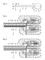
- FIG. 1 1 shows a schematic representation of an endoscope 10 with a proximal end 11 and a distal end 12.
- a shaft of which only an outer shaft tube 14 with a longitudinal axis 18 is visible, extends from the proximal end 11 to the distal end 12 of the endoscope 10 distal end 12 of the endoscope are two extreme viewing directions 22, 24 indicated, between which the viewing direction (in particular stepless) is adjustable.
- a handling device 30 with an eyepiece 32 and a coupling 34 for a light guide cable is provided. Via the coupling 34, the handling device 30 can be coupled by means of a light guide cable, not shown in the figures, to a light source for providing illumination light.
- a rotary actuator 60 and a pivot actuator 70 are also provided on the handling device 30 on the handling device 30, a rotary actuator 60 and a pivot actuator 70 are also provided.
- the rotary actuating device 60 is arranged in the transition region between the handling device 30 and the shaft 14 or at the distal end of the handling device 30 and at the proximal end of the shaft 14.
- the rotary actuator 60 has the shape of a profiled wheel, which can be rotated about the longitudinal axis 18 of the shaft 14 by means of one or more fingers of a handling device 30 to rotate the viewing direction of the endoscope 10 about the longitudinal axis 18 of the shaft 14.
- the pivoting actuating device 70 is arranged on the handling device 30 in such a way that it can be displaced along a path parallel to the longitudinal axis 18 of the shaft 14 by means of a finger of a hand holding and gripping the handling device 30, by the angle between the viewing direction 22, 24 and the longitudinal axis 18 of the shaft 14 to change.
- a light entrance window 52 is indicated, through which light from an object lying in the currently set viewing direction 22, 24 can enter the shaft 14. Subsequently, not between the light entrance window 52 and the corresponding opening on the one hand and the light entrance window 52nd distinguished window component made of an optically transparent material.
- the light entrance window 52 has, in particular, the shape of a section of a circular cylinder jacket with a cylinder axis perpendicular to the plane of the drawing FIG. 1 or the shape of a section of a spherical surface or a surface of an ellipsoid.
- FIG. 2 shows a schematic sectional view of a proximal portion of an embodiment of the endoscope 10 from FIG. 1 ,
- the cutting plane of the FIG. 2 is parallel to the drawing plane of the FIG. 1 and contains the longitudinal axis 18 (see. FIG. 1 ) of the shaft 14.
- an inner shaft tube 54 and a bundle of optical fibers 35 are arranged side by side.
- the light guides 35 lead from the coupling 34 on the handling device 30 to the distal end 12 of the endoscope 10 (cf. FIG. 1 ).
- transmitted illumination light can be transmitted from the optical fibers 35 to the distal end 12 of the endoscope 10, there emerge and illuminate an object to be observed.
- the light guides 35 are guided in a cavity so that the outer shaft tube 14 within a predetermined angular range about its longitudinal axis 18 (see. FIG. 1 ) can be rotated relative to the handling device 30.
- the inner shaft tube 54 is part of a hermetically sealed shell 50.
- the hermetically sealed shell 50 has a significantly enlarged cross-section in a region within the handling device 30 and encloses there a chamber 56, which is described below.
- the hermetically sealed shell 50 has the above with reference to FIG. 1 illustrated light entrance window 52 with a light inlet window 52 hermetically sealing window component of an optically transparent material.
- the hermetically sealed shell 50 has a light exit window 58 and a window component hermetically sealing the light exit window 58 made of an optically transparent material.
- the light exit window 58 is designed in particular as a lens and is part of the eyepiece 32 or arranged near the eyepiece 32.
- the hermetically sealed sheath 50 encloses or contains in particular in the area of the inner shaft tube 54, but also in the area of the chamber 56, an image transmission device 40 with a plurality of rod lenses 42 in a system shaft 44. Furthermore, the hermetically sealed sheath 50 encloses an objective or a lens or a plurality of lenses or mirrors as well as a pivotable mirror, a pivotable prism or another optical device for adjusting the viewing direction 22, 24 (cf. FIG. 1 ), which are not shown in the figures, at the distal end 12 of the endoscope 10.
- a substantially cylinder jacket-shaped intermediate space in which a push and pull tube is arranged as a power transmission device 26.
- the power transmission device 26 is parallel to the longitudinal axis 18 (see. FIG. 1 ) of the outer shaft tube 14 movable.
- the power transmission device 26 is mechanically coupled at the distal end 12 of the endoscope 10 with the mentioned device for adjusting the viewing direction (in particular pivotable mirror or pivotable prism). By shifting the power transmission device 26 parallel to the longitudinal axis 18 of the outer shaft tube 14, the viewing direction 22, 24 of the endoscope 10 is adjusted or changed.
- rotary actuator 60 is formed integrally with the proximal end of the outer shaft tube 14 or material, force and / or positively joined.
- a first, distal rotary bearing 62 which in FIG. 2 is indicated as a simple sliding bearing, and a first, distal seal 64 is provided.
- Proximal of the first rotary bearing 62 and the first seal 64 and in the direction parallel to the longitudinal axis 18 of the outer stem tube 14 spaced therefrom are a second, proximal rotary bearing 66 and a second, proximal seal 68 between the inner shaft tube 54 rigidly connected to the outer shaft tube 14 on the one hand and the Handling device 30 on the other hand provided.
- the rotary bearings 62, 66 allow rotation of the rotary actuator 60 together with the outer shaft tube 14, the hermetically sealed shell 50 with the devices disposed therein, and the light guides 35 (as far as the outer shaft tube 14 is located) about the longitudinal axis 18 (see. FIG. 1 ) of the outer shaft tube 14.
- the seals 64, 68 prevent largely or completely penetration of fluids and thereby caused damage to the optical fiber 35th
- pivot actuator 70 includes a push handle 72 which is disposed in a recess on the outside of the handling device 30 parallel to the longitudinal axis 18.
- the push handle 72 is arranged to be parallel to the longitudinal axis 18 by a finger of a hand gripping and holding the handling device 30 (see FIG. FIG. 1 ) is displaceable.
- the push handle 72 includes a detent ball 73, which is pressed by a detent spring 74 against a surface of the handling device 30.
- a detent ball 73 which is pressed by a detent spring 74 against a surface of the handling device 30.
- a plurality of locking grooves 37 are provided, into which the detent ball 73 can engage to hold the push handle 72 in corresponding positions.
- the push handle 72 is mechanically coupled by a push rod 76 with a magnetic coupling device 80 in the interior of the handling device 30, in particular rigidly connected.
- a seal 78 is provided to prevent ingress of fluids into the interior of the handling device 30 and in particular to the magnetic coupling device 80.
- the magnetic coupling device 80 includes an outer magnetic carrier 82 having a plurality of magnets 83 outside the hermetically sealed shell 50, and more particularly outside the chamber 56 enclosed by the hermetic shell 50. Further, the magnetic coupling device 80 includes an inner magnet carrier 84 having a plurality of magnets 85 within the enclosed by the hermetically sealed shell 50 chamber 56.
- the outer magnet carrier 82 and the inner magnet carrier 84 are each formed in particular substantially annular. A deviation from an ideal ring shape results on the outer magnetic carrier 82 in particular by the mechanical connection with the proximal end of the push rod 76. Both the outer Magnetic carrier 82 and the inner magnet carrier 84 are each parallel to the longitudinal axis 18 (see. FIG. 1 ) movable play and low friction.
- the magnets 83 on the outer magnet carrier 82 and the magnets 85 on the inner magnet carrier 84 are each designed to be movable relative to the longitudinal axis 18 (cf. FIG. 1 ) to generate rotationally symmetric magnetic fields.
- both the magnets 83 on the outer magnet carrier 82 and the magnets 85 on the inner magnet carrier 84 are each annular.
- only either the magnets 83 on the outer magnet carrier 82 or the magnets 85 on the inner magnet carrier 84 each generate a rotationally symmetrical magnetic field with respect to the longitudinal axis 18. As a result, no torque between the magnets 83 on the outer magnet carrier 82 and the magnet 85 on the inner magnet carrier 84 can be transmitted.
- FIG. 2 indicated relative arrangement of the magnetic carrier 82, 84 effect.
- a displacement of the inner magnetic carrier 84 relative to the outer magnetic carrier 82 in the direction parallel to the longitudinal axis 18 requires a strong increasing force with increasing deflection.
- the outer magnet carrier 82 and the inner magnet carrier 84 may be parallel to the longitudinal axis 18 to be moved.
- a manually caused movement of the push handle 72 by means of the push rod 76 causes a corresponding movement of the outer magnet carrier 82 and by means of the magnetic coupling between the magnet 83 on the outer magnet carrier 82 on the one hand and the magnet 85 on the inner magnet carrier 84 on the other hand, a corresponding movement of the inner magnet carrier 84th ,
- the inner magnet carrier 84 is at the same time part of a transmission 90 for transmitting, in particular reducing, a movement on the pivot actuating device 70 and the magnetic coupling device 80 on the one hand into a movement of the power transmission device 26 on the other hand, wherein the forces acting and the paths covered on the pivot actuator 70 and the magnetic coupling device 80 on the one hand differ from those of the power transmission device 26.
- the transmission 90 includes an inner cone 92 on the inner magnet carrier 84, an outer cone 96 on the proximal end of the transmission 26, balls 94 between the inner cone 92 on the inner magnet carrier 84 and the outer cone 96 on the transmission 26, a guide 95 for the balls 94 and a Compression spring 93 between the hermetically sealed shell 50 on the one hand and the power transmission device 26 on the other.
- the inner cone 92 on the inner magnet carrier 84 and the outer cone 96 on the proximal end of the force transmission device 26 each have a constant pitch and the shape of an annular section of a cone sheath.
- the slopes or the opening angles of the inner cone 92 on the inner magnet carrier 84 and the outer cone 96 on the proximal end of the force transmission device 26 differ from each other.
- the guide 95 for the balls 94 is formed by an annular and planar contact surface perpendicular to the longitudinal axis 18 of the outer shaft tube 14 (see. FIG. 1 ) educated.
- the compression spring 93 pushes the power transmission device 26 to the proximal, so that at any time the outer cone 96 at the proximal end of the power transmission device 26 abut the balls 94 and the balls 94 on the guide 95 and the inner cone 92 on the inner magnetic carrier 84.
- FIG. 3 shows a further schematic sectional view of the in FIG. 2 shown proximal portion of the embodiment of the endoscope 10 in a further configuration or situation.
- the pivoting actuating device 70, the magnetic coupling device 80 and with it the inner cone 92 on the inner magnetic carrier 84 on the one hand and the power transmission device 26 on the other hand are in the in FIG. 2 shown situation in each case in a distal position and in the FIG. 3 illustrated situation each in a proximal position.
- the different slopes or opening angles of the inner cone 92 on the inner magnet carrier 84 on the one hand and the outer cone 96 on the proximal end of the power transmission device 26 on the other hand cause a reduction or transmission of a longer path on the pivot actuator 70 and the magnetic coupling device 80 on the one hand in a shorter path at the Power transmission device 26 on the other.
- a smaller force on the pivoting actuating device 70 and on the magnetic coupling device 80 is transmitted on the one hand into a larger force on the power transmission device 26.
- the surface at the proximal end of the force transmission device 26 and / or the surface on the inner magnet carrier 84, against which the balls 94 abut may be non-conical or parallel to the longitudinal axis 18 (cf. FIG. 1 ) of the outer shaft tube 14 have varying pitch.
- the guide 95 for the balls 94 may not flat, but curved (for example, conical) to be formed. As a result, a reduction ratio varying over the path can be set.
- a guide pin 27 is provided, which engages in a guide slot 28.
- the guide slot 28 is rigidly connected to the hermetically sealed shell 50 and via this with the image transfer device 40.
- the guide pin 27 is in the guide slot 28 play and friction in the direction parallel to the longitudinal axis (see. FIG. 1 ) of the outer shaft tube 14 is movably guided.
- the guide pin 27 and the guide slot 28 form a means for positive locking of the power transmission device 26 at a rotation relative to the image transfer device 40.
- This device protects the mechanical coupling between the power transmission device 26 and a pivotable mirror or prism or a others the viewing direction 22, 24 (see. FIG. 1 ) determining means at the distal end 12 of the endoscope 10 before a torsional load.
- This inhibiting or hindering torque is alternatively or additionally avoidable by a free rotatability of the inner magnetic carrier 84 about the longitudinal axis 18 of the outer shaft tube 14 (except for mechanical friction between outer cone 96, balls 94, guide 95 and inner cone 92).
- This contributes to a changing of the angle between the viewing direction 22, 24 and the longitudinal axis 18 of the outer shaft tube 14 by means of the pivoting actuator 70 on the one hand and a rotation of the viewing direction 22, 24 about the longitudinal axis 18 of the outer shaft tube 14 by means of the rotary actuator 60 on the other hand independently and without mutual influence can take place.
- FIG. 4 shows a schematic sectional view of a proximal portion of another embodiment of the endoscope 10 from FIG. 1 .
- the type of representation and in particular the sectional plane parallel to the longitudinal axis 18 (see. FIG. 1 ) of the outer shaft tube 14 correspond to those of the illustrations in FIGS FIGS. 2 and 3 .
- the embodiment of the FIG. 4 is similar in some features, features and functions of the embodiments of FIGS. 2 and 3 , Below only features, features and functions are shown, in which the embodiment of the FIG. 4 from the embodiment of the FIGS. 2 and 3 different.
- the embodiment of the FIG. 4 differs from the embodiment of the FIGS. 2 and 3 in particular, that instead of a transmission with balls between an inner cone and an outer cone with different pitches, a gear 100 is provided with a lever 103.
- the lever 103 is coupled to a carriage 102 by means of a pivoting joint 104.
- the carriage 102 is in the chamber 56 within the hermetically sealed shell 50 freely about the longitudinal axis 18 (see. FIG. 1 ) of the outer shaft tube 14 rotatably play and low friction positively guided.
- the pivot joint 104 defines a pivot axis perpendicular to the longitudinal axis 18 of the outer shaft tube 14 and in the in FIG. 4 shown position of the carriage 102 perpendicular to the cutting plane of the FIG. 4 is.
- the lever 103 has an inner magnet carrier 84 with a plurality of magnets 85.
- the inner magnet carrier 84 is not displaceable parallel to the longitudinal axis 18 of the outer shaft tube 14, but about the pivot axis defined by the pivot joint 104 pivotally.
- the magnets 83 on the outer magnet carrier 82 and the magnets 85 on the inner magnet carrier 84 are arranged and formed, in particular polarized, that each linear translational movement of the outer magnet carrier 82, a corresponding pivotal movement of the inner magnet carrier 84 and thus of the lever 103 by the pivot joint 104th defined pivot axis causes.
- the lever 103 has an opening 105 into which the proximal end of the power transmission device 26 engages.
- the lever 103 surrounds the opening 105 in the shape of a frame.
- a pin 106 is provided parallel to the pivot axis defined by the pivot 104.
- the pin 106 engages in a circumferential groove 107 on the power transmission device 26.
- the pin 106 on the lever 103 and the circumferential groove 107 on the power transmission device 26 are formed so that they play and a low-friction, positive mechanical coupling of the lever 103 with the power transmission device 26 for forces parallel to the longitudinal axis 18 (see. FIG. 1 ) of the outer shaft tube 14 and at the same time not hinder or inhibit rotation of the lever 103 (together with the carriage 102) about the longitudinal axis 18 of the outer shaft tube 14 relative to the power transmission device 26.
- Deviating from the illustration in FIG. 4 can be similar to the embodiment of the FIGS. 2 and 3 a guide pin in a guide slot or other means for positively locking the power transmission device 26 may be provided at a rotation relative to the image transfer device 40.
- a movement of the pivoting actuating device 70 and by means of the push rod 76 of the magnetic coupling device 80 causes a corresponding pivoting movement 103 and due to the positive coupling between the pin 106 on the lever 103 and the circumferential groove 107 on the power transmission device 26, a movement of the power transmission device 26 parallel to the longitudinal axis 18 (see , FIG. 1 ) of the outer shaft tube 14.
- FIG. 5 shows a further schematic representation of the proximal portion of the embodiment FIG. 4 of the endoscope 10.
- the type of representation, in particular the sectional plane, corresponds to that of the FIGS. 2 to 4 .
- FIG. 5 illustrated situation differs from that in FIG. 4 illustrated in that the pivoting actuator 70 and the magnetic coupling device 80 on the one hand and with these by means of the transmission 100 and the power transmission device 26 are moved proximally.
- the ratio of the distance of the pin 106 from the pivot axis defined by the pivot 104 and the distance of the magnetic coupling 80 from the pivot axis defined by the pivot 104 causes a corresponding reduction of a longer path and a smaller force on the pivot actuator 70 and the Magnetic coupling device 80 in a shorter path and a larger force on the power transmission 26th
- the magnets 83 on the outer magnet carrier 82 are in particular arranged and polarized in such a way that they are parallel to the longitudinal axis 18 (cf. FIG. 1 ) of the outer shaft tube 14 generate rotationally symmetric magnetic field.
- This embodiment prevents a torque which causes, inhibits or obstructs rotation of the lever 103 (together with the carriage 102) about the longitudinal axis 18. Such inhibiting or hindering torque is further mitigated by the described free rotatability of the lever 103 together with the inner magnet carrier 84 and the carriage 102 about the longitudinal axis 18 of the outer stem tube 14 (except for friction between carriage 102 and hermetically sealed sheath 50).
- FIG. 1 illustrated endoscope 10 and in particular in each of the basis of the FIGS. 2 to 5 illustrated embodiments, one in the figures not shown display of the currently set angle can be provided.
- a scale with numbers or other symbols the value of the angle between the viewing direction 22, 24 (see. FIG. 1 ) and longitudinal axis 18 of the outer shaft tube 14, and on the push handle 72 or with this mechanically coupled a pointer pointing to the scale provided.
- a window may be provided on or mechanically coupled to the push handle 72 which highlights a value or symbol on the scale.
- the scale may be mechanically coupled to or coupled to push handle 72, and the pointer, window, or other visible highlighting device may be provided on the housing of handler 30.
Landscapes
- Health & Medical Sciences (AREA)
- Life Sciences & Earth Sciences (AREA)
- Surgery (AREA)
- Physics & Mathematics (AREA)
- Optics & Photonics (AREA)
- Engineering & Computer Science (AREA)
- Biomedical Technology (AREA)
- Molecular Biology (AREA)
- Pathology (AREA)
- Nuclear Medicine, Radiotherapy & Molecular Imaging (AREA)
- Biophysics (AREA)
- Heart & Thoracic Surgery (AREA)
- Medical Informatics (AREA)
- Radiology & Medical Imaging (AREA)
- Animal Behavior & Ethology (AREA)
- General Health & Medical Sciences (AREA)
- Public Health (AREA)
- Veterinary Medicine (AREA)
- Mechanical Engineering (AREA)
- Endoscopes (AREA)
- Instruments For Viewing The Inside Of Hollow Bodies (AREA)
Abstract
Description
- Die vorliegende Erfindung ist auf ein Endoskop mit einstellbarer Blickrichtung und dabei insbesondere auf die Kopplung zwischen einer Betätigungseinrichtung und der Einstellung der Blickrichtung gerichtet.
- Neben Endoskopen mit fester Blickrichtung parallel oder in einem Winkel zur Längsachse des Schafts werden zunehmend Endoskope mit einstellbarer Blickrichtung verwendet. Eine freie Einstellbarkeit der Blickrichtung innerhalb eines vorbestimmten Winkelbereichs kann eine wesentlich flexiblere Anwendung ermöglichen und damit medizinischem Personal ein schnelleres, entspannteres und damit auch sichereres und ökonomischeres Arbeiten ermöglichen.
- Um ein Autoklavieren eines Endoskops und damit seine mehrfache medizinische Verwendung zu ermöglichen, muss der Strahlengang des Endoskops durch eine hermetisch dichte Hülle gegen das Eindringen von Feuchtigkeit auch bei hoher Temperatur und Überdruck geschützt sein. Zur Übertragung von an einer Betätigungseinrichtung außerhalb der hermetisch dichten Hülle erzeugten Kräften und Bewegungen in das Innere der hermetisch dichten Hülle wurden mehrere Konzepte entwickelt, die auf einer magnetischen Kopplung beruhen zwischen Magneten außerhalb und innerhalb der hermetisch dichten Hülle beruhen.
- In
EP 0 907 900 B1 (erstmals veröffentlicht alsWO 98/44376 A1 - In
EP 2 353 493 A1 ist ein medizinisches Instrument mit einem magnetischen Stellantrieb beschrieben. Je ein oder mehrere Magneten außerhalb und innerhalb einer hermetisch dichten Hülle sind sowohl axial verschiebbar als auch um eine gemeinsame Achse rotierbar, um sowohl axiale Kräfte als auch Drehmomente durch magnetische Kopplung zu übertragen. Axiale Kräfte sind zur Fokussierung oder für andere Vorgänge übertragbar (Absatz [0019]). - In
EP 2 430 970 A2 undEP 2 430 971 A2 sind Endoskope mit einstellbarer Blickrichtung beschrieben. Eine Drehbewegung eines Betätigungselements wird mittels eines Getriebes in eine axiale Bewegung eines Zugrohrs umgesetzt. -
DE 10 2011 012 426 A1 ist ein endoskopisches Instrument zur Einhandbedienung beschrieben. Ein Stellelement ist an der Außenseite des Instruments so angeordnet, dass es ergonomisch mit einem Finger einer das Instrument haltenden Hand verschiebbar ist, um eine Blickrichtung des endoskopischen Instruments einzustellen (Absätze [0009], [0036], [0051]). - Eine Aufgabe der vorliegenden Erfindung besteht darin, ein verbessertes Endoskop mit einstellbarer Blickrichtung zu schaffen.
- Diese Aufgabe wird durch die Gegenstände der unabhängigen Ansprüche gelöst. Weiterbildungen sind in den abhängigen Ansprüchen angegeben.
- Ein Endoskop mit einstellbarer Blickrichtung umfasst einen Schaft, eine Bildübertragungseinrichtung zum Übertragen eines Bilds von einem distalen Ende des Endoskops zu einem proximalen Ende des Endoskops, eine hermetisch dichte Hülle um die Bildübertragungseinrichtung mit einem Lichteintrittsfenster am distalen Ende des Endoskops, eine Handhabungseinrichtung am proximalen Ende des Endoskops, eine Schwenkbetätigungseinrichtung an der Handhabungseinrichtung zum manuellen Einstellen eines Winkels zwischen der Blickrichtung und einer Längsachse des Schafts, eine Magnetkopplungseinrichtung zum magnetischen Übertragen einer Kraft parallel zur Längsachse des Schafts zwischen der Schwenkbetätigungseinrichtung und einer Kraftübertragungseinrichtung innerhalb der hermetisch dichten Hülle und eine Drehbetätigungseinrichtung an der Handhabungseinrichtung zum manuellen Rotieren der Blickrichtung um die Längsachse des Schafts relativ zur Handhabungseinrichtung.
- Das Endoskop ist insbesondere ein medizinisches Endoskop bzw. ein Endoskop für mikroinvasive diagnostische und chirurgische Eingriffe oder für andere medizinische Eingriffe. Mit einer einstellbaren Blickrichtung ist eine Blickrichtung gemeint, die nicht nur um die Längsachse des Schafts des Endoskops rotierbar, sondern deren Winkel zur Längsachse des Schafts ferner einstellbar ist. Der Schaft des Endoskops ist insbesondere starr und insbesondere gerade. Die Bildübertragungseinrichtung umfasst insbesondere im Fall eines geraden und starren Schafts ein Stablinsensystem aus einer Mehrzahl von Stablinsen. Im Fall eines gekrümmten oder krümmbaren Schafts kann die Bildübertragungseinrichtung ein geordnetes Bündel von Lichtleitfasern umfassen. Alternativ kann die Bildübertragungseinrichtung zur elektronischen Übertragung eines Bilds ausgebildet sein, wobei von einem Objekt ausgehendes Licht von einer Kamera am oder nahe dem distalen Ende des Schafts in ein elektronisches Signal gewandelt wird, das das erfasste Bild darstellt und zum proximalen Ende des Endoskops übertragen wird.
- Bestandteil der hermetisch dichten Hülle ist insbesondere ein Rohr, das sich vom distalen Ende des Schafts bis zur Handhabungseinrichtung erstreckt, und das insbesondere innerhalb eines Außenschaftrohrs angeordnet ist. Das Außenschaftrohr kann neben diesem Rohr, das Teil der hermetisch dichten Hülle ist, Lichtleiter zur Übertragung von Beleuchtungslicht vom proximalen Ende zum distalen Ende des Endoskops umfassen. Alternativ oder zusätzlich kann das Außenschaftrohr einen oder mehrere Kanäle zum Aufnehmen von einem oder mehreren medizinischen Instrumenten, zum Leiten eines Spülfluids und zum Absaugen von Fluiden und/oder Gewebestücken oder anderen Partikeln umfassen.
- Das Lichteintrittsfenster der hermetisch dichten Hülle am distalen Ende des Endoskops ist durch ein hermetisch dicht in das Lichteintrittsfenster gefügtes Fensterbauteil aus einem optisch transparenten Material verschlossen. Insbesondere wenn die Bildübertragungseinrichtung zum optischen Übertragen eines Bilds ausgebildet ist, umfasst die hermetisch dichte Hülle ferner ein Lichtaustrittsfenster, das durch ein entsprechendes Fensterbauteil aus einem optisch transparenten Material verschlossen ist, am proximalen Ende des Endoskops. Sowohl das Lichteintrittsfenster als auch gegebenenfalls das Lichtaustrittsfenster können jeweils eben oder gekrümmt und ferner als Linsen oder Prismen ausgebildet sein.
- Die Handhabungseinrichtung weist insbesondere die Gestalt eines ergonomisch vorteilhaft ausgestalteten Griffs auf. Die Schwenkbetätigungseinrichtung und die Drehbetätigungseinrichtung sind insbesondere so an der Handhabungseinrichtung angeordnet, dass sie jeweils mit einem oder mehreren Fingern einer die Handhabungseinrichtung greifenden und haltenden Hand ohne Weiteres betätigt werden können.
- Die Kraftübertragungseinrichtung innerhalb der hermetisch dichten Hülle ist ausgebildet, um eine mittels der Schwenkbetätigungseinrichtung manuell erzeugte Kraft und eine entsprechende Bewegung zum Einstellen des Winkels zwischen Blickrichtung und Längsachse des Schafts zum distalen Ende des Endoskops zu übertragen. Am distalen Ende des Endoskops ist die Kraftübertragungseinrichtung insbesondere mit einem schwenkbaren oder anderweitig bewegbaren Spiegel oder Prisma oder einer anderen optischen Einrichtung zum Einstellen der Blickrichtung mechanisch gekoppelt.
- Die Drehbetätigungseinrichtung ist insbesondere zum manuellen Rotieren der Bildübertragungseinrichtung und insbesondere auch zum manuellen Rotieren der hermetisch dichten Hülle um die Längsachse des Schafts ausgebildet.
- Die Ausgestaltung der Magnetkopplungseinrichtung zum magnetischen Übertragen einer Kraft parallel zur Längsachse des Schafts kann eine unerwartet einfache Konstruktion und Fertigung ermöglichen. Dazu kann ferner beitragen, dass die Drehbetätigungseinrichtung rein mechanisch ausgebildet sein kann und die Magnetkopplungseinrichtung lediglich zum Übertragen einer Kraft zwischen der Schwenkbetätigungseinrichtung und der Kraftübertragungseinrichtung ausgebildet sein kann.
- Bei einem Endoskop, wie es hier beschrieben ist, ist insbesondere die Kraftübertragungseinrichtung parallel zur Längsachse des Schafts verschiebbar und erstreckt sich von der Magnetkopplungseinrichtung bis zum distalen Ende des Endoskops.
- Bei einem Endoskop, wie es hier beschrieben ist, ist die Magnetkopplungseinrichtung insbesondere ausgebildet, um kein Drehmoment zu übertragen.
- Insbesondere ist die Magnetkopplungseinrichtung ausgebildet, um kein Drehmoment um die Längsachse des Schafts zu übertragen. Dazu weist die Magnetkopplungseinrichtung insbesondere ein durch einen oder mehrere Permanentmagneten erzeugtes Magnetfeld auf, das rotationssymmetrisch zur Längsachse des Schafts ist.
- Die Ausbildung der Magnetkopplungseinrichtung derart, dass sie kein Drehmoment überträgt, kann ermöglichen, dass die Kraftübertragungseinrichtung und mit ihr insbesondere auch die Bildübertragungseinrichtung ohne eine Rückwirkung auf den Winkel zwischen Blickrichtung und Längsachse des Schafts um die Längsachse des Schafts rotiert werden kann. Dies kann ermöglichen, dass ein Schwenken der Blickrichtung (Verändern des Winkels zwischen Blickrichtung und Längsachse des Schafts) und ein Rotieren der Blickrichtung um die Längsachse des Schafts völlig unabhängig voneinander erfolgen können. Dabei hat insbesondere weder eine Betätigung der Schwenkbetätigungseinrichtung eine Rotation der Blickrichtung um die Längsachse des Schafts noch eine Betätigung der Drehbetätigungseinrichtung eine Veränderung des Winkels zwischen Blickrichtung und Längsachse des Schafts zur Folge. Allein durch die Ausgestaltung der Magnetkopplungseinrichtung derart, dass sie kein Drehmoment überträgt, kann eine besonders einfache Handhabung des Endoskops ermöglicht werden.
- Bei einem Endoskop, wie es hier beschrieben ist, ist die Schwenkbetätigungseinrichtung insbesondere mittels eines Fingers einer die Handhabungseinrichtung greifenden Hand entlang eines vorbestimmten Pfads verschiebbar.
- Die Schwenkbetätigungseinrichtung ist insbesondere entlang eines geraden und insbesondere zur Längsachse des Schafts parallelen Pfads verschiebbar. Die Schwenkbetätigungs-einrichtung ist an der Handhabungseinrichtung ergonomisch vorteilhaft angeordnet. Dazu ist die Schwenkbetätigungseinrichtung insbesondere derart an der Handhabungseinrichtung angeordnet, dass beim Ergreifen der Handhabungseinrichtung mit einer Hand ohne Weiteres und ohne eine von einem natürlichen Bewegungsablauf abweichende Bewegung ein Finger an der Schwenkbetätigungseinrichtung zu liegen kommt.
- Bei einem Endoskop, wie es hier beschrieben ist, ist die Drehbetätigungseinrichtung insbesondere am distalen Ende der Handhabungseinrichtung angeordnet.
- Die Drehbetätigungseinrichtung ist insbesondere im Übergangsbereich zwischen Handhabungseinrichtung und Schaft angeordnet. Diese Anordnung kann ergonomisch vorteilhaft sein, insbesondere ein manuelles Rotieren der Blickrichtung um die Längsachse des Schafts mittels eines oder zweier Finger einer die Handhabungseinrichtung greifenden und haltenden Hand ermöglichen.
- Bei einem Endoskop, wie es hier beschrieben ist, ist die Drehbetätigungseinrichtung insbesondere mit einem proximalen Bereich eines Außenschaftrohrs starr verbunden.
- Die Drehbetätigungseinrichtung weist insbesondere im Wesentlichen die Gestalt eines Rads oder Rings auf, dessen äußerer Umfang geriffelt, profiliert oder auf andere Weise so gestaltet sein kann, dass zur Betätigung nicht allein ein Kraftschluss zwischen den betätigenden Fingern und der Drehbetätigungseinrichtung erforderlich ist, sondern auch Formschluss ohne Weiteres herstellbar ist. Die Ausgestaltung der Drehbetätigungseinrichtung als Rad oder Ring kann eine besonders intuitive Bedienung, insbesondere eine intuitive Rotation der Blickrichtung um die Längsachse des Schafts, ermöglichen.
- Ein Endoskop, wie es hier beschrieben ist, umfasst insbesondere ferner ein Getriebe zum Übertragen einer ersten Kraft und eines ersten Wegs an der Schwenkbetätigungseinrichtung in eine zweite Kraft und einen zweiten Weg an der Kraftübertragungseinrichtung, wobei die Kraftübertragungseinrichtung parallel zur Längsachse des Schafts verschiebbar ist und sich von der Handhabungseinrichtung bis zum distalen Ende des Endoskops erstreckt.
- Das Getriebe umfasst insbesondere einen oder mehrere Hebel oder eine oder mehrere in radialer Richtung bewegbare Kugeln zwischen konischen Flächen unterschiedlicher Steigungen an An- und Abtrieb des Getriebes. Das Getriebe ist insbesondere ein Untersetzungsgetriebe zum Übertragen einer kleineren Kraft und eines längeren Wegs an der Schwenkbetätigungseinrichtung in eine größere Kraft und einen kürzeren Weg an der Kraftübertragungseinrichtung. Das Getriebe ist insbesondere zwischen der Magnetkopplungseinrichtung und der Kraftübertragungseinrichtung angeordnet und mit diesen jeweils teilweise integriert.
- Die zum Verstellen des Winkels zwischen Blickrichtung und Längsachse des Schafts erforderlichen Wege der Kraftübertragungseinrichtung sind in der Regel im Verhältnis zu der an einer Betätigungseinrichtung manuell erzeugbaren Bewegung kurz. Die Anordnung eines Untersetzungsgetriebes zwischen der Schwenkbetätigungseinrichtung und der Kraftübertragungseinrichtung kann eine feinfühligere manuelle Einstellung des Winkels zwischen Blickrichtung und Längsachse des Schafts vereinfachen.
- Bei einem Endoskop, wie es hier beschrieben ist, umfasst insbesondere die Magnetkopplungseinrichtung ein ringförmiges Bauteil mit einer rotationssymmetrischen Innenfläche, deren Durchmesser in einer Richtung parallel zur Längsachse des Schafts kontinuierlich zunimmt, innerhalb der hermetisch dichten Hülle.
- An dem ringförmigen Bauteil innerhalb der hermetisch dichten Hülle ist insbesondere eine rotationssymmetrische Anordnung von einem oder mehreren Magneten bzw. eine Anordnung von einem oder mehreren Magneten, die ein zur Längsachse des Schafts rotationssymmetrisches Magnetfeld erzeugen, vorgesehen. Die rotationssymmetrische Innenfläche ist insbesondere konisch bzw. weist die Gestalt einer Mantelfläche eines Kreiskegelstumpfs oder eines anderen Ausschnitts einer Mantelfläche eines Kreiskegels auf.
- Bei einem Endoskop, wie es hier beschrieben ist, ist das ringförmige Bauteil insbesondere parallel zur Längsachse des Schafts bewegbar und um die Längsachse des Schafts rotierbar.
- Die Rotierbarkeit des ringförmigen Bauteils um die Längsachse des Schafts kann eine alternative oder zusätzliche Maßnahme zur bereits in anderem Zusammenhang beschriebenen Entkopplung des Schwenkens und des Rotierens der Blickrichtung bilden und so einen Beitrag zur intuitiven und ökonomischen Handhabung des Endoskops leisten.
- Bei einem Endoskop, wie es hier beschrieben ist, bewirkt insbesondere eine Rotation des ringförmigen Bauteils keine Änderung des Winkels zwischen Blickrichtung und Längsachse des Schafts und keine Rotation der Blickrichtung um die Längsachse des Schafts.
- Bei einem Endoskop, wie es hier beschrieben ist, ist die Kraftübertragungseinrichtung insbesondere rohrförmig und umgibt die Bildübertragungseinrichtung im Wesentlichen mantelförmig.
- Abweichungen der Kraftübertragungseinrichtung von einer rohrförmigen bzw. zylindermantelförmigen (insbesondere kreiszylindermantelförmigen) Gestalt können insbesondere in einer oder mehreren Öffnungen bzw. Ausnehmungen bestehen. Weitere Abweichungen von einer ideal rohrförmigen bzw. zylindermantelförmigen Gestalt bestehen insbesondere an den Enden der Kraftübertragungseinrichtung. Insbesondere an diesen Enden kann die Kraftübertragungseinrichtung ferner ausgebildet sein, um die Bildübertragungseinrichtung nicht mantelförmig zu umgeben.
- Bei einem Endoskop, wie es hier beschrieben ist, ist die Kraftübertragungseinrichtung insbesondere durch eine Einrichtung formschlüssig an einer Rotation relativ zur Bildübertragungseinrichtung gehindert.
- Die Einrichtung zum Hindern der Kraftübertragungseinrichtung an einer Rotation relativ zur Bildübertragungseinrichtung umfasst insbesondere einen Stift, der in ein Langloch eingreift, wobei der Stift an der Kraftübertragungseinrichtung und das Langloch an der Bildübertragungseinrichtung oder an der hermetisch dichten Hülle vorgesehen sein kann oder umgekehrt.
- Bei einem Endoskop, wie es hier beschrieben ist, ist das Außenschaftrohr insbesondere mit der hermetisch dichten Hülle gekoppelt.
- Insbesondere sind Außenschaftrohr und die hermetisch dichte Hülle mechanisch starr miteinander verbunden. Die mechanisch starre Verbindung oder andersartige mechanische Kopplung zwischen Außenschaftrohr und hermetisch dichter Hülle ist insbesondere zwischen den distalen Enden des Außenschaftrohrs und der hermetisch dichten Hülle vorgesehen. In diesem Fall kann proximal der distalen Enden von Außenschaftrohr und hermetisch dichter Hülle ein Zwischenraum vorgesehen sein. In diesem Zwischenraum können ein oder mehrere Lichtleiter zum Übertragen von Beleuchtungslicht und/oder ein oder mehrere Kanäle zum Aufnehmen medizinischer Instrumente, zum Leiten eines Spülfluids und zum Absaugen von Fluiden und Partikeln vorgesehen sein.
- Bei einem Endoskop, wie es hier beschrieben ist, können die hermetisch dichte Hülle und die Bildübertragungseinrichtung mechanisch starr miteinander verbunden oder auf andere Weise mechanisch gekoppelt sein. Die hermetisch dichte Hülle und die Bildübertragungseinrichtung sind insbesondere am distalen Ende des Endoskops und/oder im Bereich der Handhabungseinrichtung miteinander starr verbunden. Dazwischen kann ein mantelförmiger (insbesondere kreiszylindermantelförmiger oder anders zylindermantelförmiger) Zwischenraum vorgesehen sein, in dem die Kraftübertragungseinrichtung angeordnet ist.
- Ein Endoskop, wie es hier beschrieben ist, umfasst insbesondere ferner eine von außen ablesbare Anzeige des momentan eingestellten Winkels zwischen Blickrichtung und Längsachse des Schafts.
- Die von außen ablesbare Anzeige ist insbesondere von außen sichtbar und damit visuell ablesbar. Die Anzeige kann eine Skala und einen Zeiger oder ein Fenster zur Sichtbarmachung von einem oder mehreren Zahlen oder anderen Indikatoren der Skala umfassen.
- Ein Endoskop, wie es hier beschrieben ist, ist insbesondere so ausgebildet, dass eine Betätigung der Drehbetätigungseinrichtung keinen Einfluss auf den eingestellten Winkel zwischen der Blickrichtung und der Längsachse des Schafts hat.
- Nachfolgend werden Ausführungsformen anhand der beigefügten Figuren näher erläutert. Es zeigen:
- Figur 1
- eine schematische Darstellung eines Endoskops mit einstellbarer Blickrichtung;
- Figur 2
- eine schematische Schnittdarstellung eines proximalen Bereichs einer Ausführungsform des Endoskops aus
Figur 1 ; - Figur 3
- eine weitere schematische Schnittdarstellung des proximalen Bereichs der Ausführungsform aus
Figur 2 ; - Figur 4
- eine schematische Schnittdarstellung eines proximalen Bereichs einer weiteren Ausführungsform des Endoskops aus
Figur 1 ; - Figur 5
- eine weitere schematische Schnittdarstellung des proximalen Bereichs der Ausführungsform aus
Figur 4 . -
Figur 1 zeigt eine schematische Darstellung eines Endoskops 10 mit einem proximalen Ende 11 und einem distalen Ende 12. Ein Schaft, von dem nur ein Außenschaftrohr 14 mit einer Längsachse 18 sichtbar ist, erstreckt sich vom proximalen Ende 11 bis zum distalen Ende 12 des Endoskops 10. Am distalen Ende 12 des Endoskops sind zwei extreme Blickrichtungen 22, 24 angedeutet, zwischen denen die Blickrichtung (insbesondere stufenlos) einstellbar ist. - Am proximalen Ende 11 des Endoskops 10 ist eine Handhabungseinrichtung 30 mit einem Okular 32 und einer Kupplung 34 für ein Lichtleitkabel vorgesehen. Über die Kupplung 34 ist die Handhabungseinrichtung 30 mittels eines in den Figuren nicht dargestellten Lichtleitkabels mit einer Lichtquelle zum Bereitstellen von Beleuchtungslicht koppelbar.
- An der Handhabungseinrichtung 30 sind ferner eine Drehbetätigungseinrichtung 60 und eine Schwenkbetätigungseinrichtung 70 vorgesehen. Die Drehbetätigungseinrichtung 60 ist im Übergangsbereich zwischen der Handhabungseinrichtung 30 und dem Schaft 14 bzw. am distalen Ende der Handhabungseinrichtung 30 und am proximalen Ende des Schafts 14 angeordnet. Die Drehbetätigungseinrichtung 60 weist die Gestalt eines profilierten Rads auf, das mittels eines oder mehrerer Finger einer die Handhabungseinrichtung 30 greifenden Hand um die Längsachse 18 des Schafts 14 gedreht werden kann, um die Blickrichtung des Endoskops 10 um die Längsachse 18 des Schafts 14 zu rotieren. Die Schwenkbetätigungseinrichtung 70 ist so an der Handhabungseinrichtung 30 angeordnet, dass sie mittels eines Fingers einer die Handhabungseinrichtung 30 greifenden und haltenden Hand entlang eines Pfads parallel zur Längsachse 18 des Schafts 14 verschiebbar ist, um den Winkel zwischen der Blickrichtung 22, 24 und der Längsachse 18 des Schafts 14 zu verändern.
- Am distalen Ende 12 des Endoskops 10 ist ein Lichteintrittsfenster 52 angedeutet, durch das Licht von einem in der momentan eingestellten Blickrichtung 22, 24 liegenden Gegenstand in den Schaft 14 eintreten kann. Nachfolgend wird nicht zwischen dem Lichteintrittsfenster 52 bzw. der entsprechenden Öffnung einerseits und dem das Lichteintrittsfenster 52 verschließenden Fensterbauteil aus einem optisch transparenten Material unterschieden. Das Lichteintrittsfenster 52 weist insbesondere die Gestalt eines Ausschnitts eines Kreiszylindermantels mit Zylinderachse senkrecht zur Zeichenebene der
Figur 1 oder die Gestalt eines Ausschnitts einer Kugeloberfläche oder einer Oberfläche eines Ellipsoids auf. -
Figur 2 zeigt eine schematische Schnittdarstellung eines proximalen Bereichs einer Ausführungsform des Endoskops 10 ausFigur 1 . Die Schnittebene derFigur 2 ist parallel zur Zeichenebene derFigur 1 und enthält die Längsachse 18 (vgl.Figur 1 ) des Schafts 14. - Im Außenschaftrohr 14 des Endoskops 10 sind nebeneinander ein Innenschaftrohr 54 und ein Bündel Lichtleiter 35 angeordnet. Die Lichtleiter 35 führen von der Kupplung 34 an der Handhabungseinrichtung 30 zum distalen Ende 12 des Endoskops 10 (vgl.
Figur 1 ). Mittels eines in den Figuren nicht dargestellten Lichtleitkabels von einer Lichtquelle zur Kupplung 34 an der Handhabungseinrichtung 30 übertragenes Beleuchtungslicht kann von den Lichtleitern 35 zum distalen Ende 12 des Endoskops 10 übertragen werden, dort austreten und einen zu beobachtenden Gegenstand beleuchten. Zwischen der Kupplung 34 und dem Außenschaftrohr 14 sind die Lichtleiter 35 in einem Hohlraum so geführt, dass das Außenschaftrohr 14 innerhalb eines vorbestimmten Winkelbereichs um seine Längsachse 18 (vgl.Figur 1 ) relativ zur Handhabungseinrichtung 30 rotiert werden kann. - Das Innenschaftrohr 54 ist Bestandteil einer hermetisch dichten Hülle 50. Die hermetisch dichte Hülle 50 weist in einem Bereich innerhalb der Handhabungseinrichtung 30 einen deutlich vergrößerten Querschnitt auf und umschließt dort eine Kammer 56, die unten beschrieben ist. Am distalen Ende 12 des Endoskops 10 weist die hermetisch dichte Hülle 50 das oben anhand der
Figur 1 dargestellte Lichteintrittsfenster 52 mit einem das Lichteintrittsfenster 52 hermetisch dicht verschließenden Fensterbauteil aus einem optisch transparenten Material auf. Am proximalen Ende 11 des Endoskops 10 weist die hermetisch dichte Hülle 50 ein Lichtaustrittsfenster 58 und ein das Lichtaustrittsfenster 58 hermetisch dicht verschließendes Fensterbauteil aus einem optisch transparenten Material auf. Das Lichtaustrittsfenster 58 ist insbesondere als Linse ausgebildet und Bestandteil des Okulars 32 oder nahe dem Okular 32 angeordnet. - Die hermetisch dichte Hülle 50 umschließt bzw. enthält insbesondere im Bereich des Innenschaftrohrs 54, aber auch im Bereich der Kammer 56, eine Bildübertragungseinrichtung 40 mit einer Mehrzahl von Stablinsen 42 in einem Systemschaft 44. Ferner umschließt die hermetisch dichte Hülle 50 ein Objektiv bzw. eine oder mehrere Linsen oder Spiegel sowie einen schwenkbaren Spiegel, ein schwenkbares Prisma oder eine andere optische Einrichtung zum Einstellen der Blickrichtung 22, 24 (vgl.
Figur 1 ), die in den Figuren nicht dargestellt sind, am distalen Ende 12 des Endoskops 10. - Zwischen dem Innenschaftrohr 54 und dem Systemschaft 44 befindet sich ein im Wesentlichen zylindermantelförmiger Zwischenraum, in dem ein Schub- und Zugrohr als Kraftübertragungseinrichtung 26 angeordnet ist. Die Kraftübertragungseinrichtung 26 ist parallel zur Längsachse 18 (vgl.
Figur 1 ) des Außenschaftrohrs 14 bewegbar. Die Kraftübertragungseinrichtung 26 ist am distalen Ende 12 des Endoskops 10 mit der erwähnten Einrichtung zum Einstellen der Blickrichtung (insbesondere schwenkbarer Spiegel oder schwenkbares Prisma) mechanisch gekoppelt. Durch Verschiebung der Kraftübertragungseinrichtung 26 parallel zur Längsachse 18 des Außenschaftrohrs 14 wird die Blickrichtung 22, 24 des Endoskops 10 verstellt bzw. verändert. - Die bereits oben anhand der
Figur 1 dargestellte Drehbetätigungseinrichtung 60 ist mit dem proximalen Ende des Außenschaftrohrs 14 einstückig ausgebildet oder stoff-, kraft- und/oder formschlüssig gefügt. Zwischen der Drehbetätigungseinrichtung 60 und der Handhabungseinrichtung 30 sind ein erstes, distales Rotationslager 62, das inFigur 2 als einfaches Gleitlager angedeutet ist, und eine erste, distale Dichtung 64 vorgesehen. Proximal des ersten Rotationslagers 62 und der ersten Dichtung 64 und in Richtung parallel zur Längsachse 18 des Außenschaftrohrs 14 von diesen beabstandet sind ein zweites, proximales Rotationslager 66 und eine zweite, proximale Dichtung 68 zwischen dem mit dem Außenschaftrohr 14 starr verbundenen Innenschaftrohr 54 einerseits und der Handhabungseinrichtung 30 andererseits vorgesehen. Die Rotationslager 62, 66 ermöglichen eine Rotation der Drehbetätigungseinrichtung 60 zusammen mit dem Außenschaftrohr 14, der hermetisch dichten Hülle 50 mit den darin angeordneten Einrichtungen und der Lichtleiter 35 (soweit sie im Bereich des Außenschaftrohrs 14 angeordnet sind) um die Längsachse 18 (vgl.Figur 1 ) des Außenschaftrohrs 14. Die Dichtungen 64, 68 verhindern weitgehend oder vollständig ein Eindringen von Fluiden und eine dadurch hervorgerufene Beschädigung der Lichtleiter 35. - Die bereits oben in Zusammenhang mit
Figur 1 erwähnte Schwenkbetätigungseinrichtung 70 umfasst einen Schiebegriff 72, der in einer Ausnehmung an der Außenseite der Handhabungseinrichtung 30 parallel zur Längsachse 18 angeordnet ist. Der Schiebegriff 72 ist so angeordnet, dass er durch einen Finger einer Hand, die die Handhabungseinrichtung 30 greift und hält, parallel zur Längsachse 18 (vgl.Figur 1 ) verschiebbar ist. - Der Schiebegriff 72 umfasst eine Rastkugel 73, die durch eine Rastfeder 74 gegen eine Oberfläche der Handhabungseinrichtung 30 gedrückt wird. In der genannten Oberfläche der Handhabungseinrichtung 30 sind mehrere Rastnuten 37 vorgesehen, in die die Rastkugel 73 eingreifen kann, um den Schiebegriff 72 in korrespondierenden Positionen zu halten.
- Der Schiebegriff 72 ist durch eine Schubstange 76 mit einer Magnetkopplungseinrichtung 80 im Inneren der Handhabungseinrichtung 30 mechanisch gekoppelt, insbesondere starr verbunden. An der Schubstange 76 ist eine Dichtung 78 vorgesehen, um ein Eindringen von Fluiden in das Innere der Handhabungseinrichtung 30 und insbesondere zur Magnetkopplungseinrichtung 80 zu verhindern.
- Die Magnetkopplungseinrichtung 80 umfasst einen äußeren Magnetträger 82 mit einer Mehrzahl von Magneten 83 außerhalb der hermetisch dichten Hülle 50 und insbesondere außerhalb der durch die hermetisch dichte Hülle 50 umschlossenen Kammer 56. Ferner umfasst die Magnetkopplungseinrichtung 80 einen inneren Magnetträger 84 mit einer Mehrzahl von Magneten 85 innerhalb der durch die hermetisch dichte Hülle 50 umschlossenen Kammer 56. Der äußere Magnetträger 82 und der innere Magnetträger 84 sind jeweils insbesondere im Wesentlichen ringförmig ausgebildet. Eine Abweichung von einer idealen Ringform ergibt sich am äußeren Magnetträger 82 insbesondere durch die mechanische Verbindung mit dem proximalen Ende der Schubstange 76. Sowohl der äußere Magnetträger 82 als auch der innere Magnetträger 84 sind jeweils parallel zur Längsachse 18 (vgl.
Figur 1 ) bewegbar spiel- und reibungsarm geführt. - Die Magneten 83 am äußeren Magnetträger 82 und die Magneten 85 am inneren Magnetträger 84 sind jeweils ausgebildet, um zur Längsachse 18 (vgl.
Figur 1 ) rotationssymmetrische Magnetfelder zu erzeugen. Insbesondere sind sowohl die Magneten 83 am äußeren Magnetträger 82 als auch die Magneten 85 am inneren Magnetträger 84 jeweils kreisringförmig. Alternativ erzeugen lediglich entweder die Magneten 83 am äußeren Magnetträger 82 oder die Magneten 85 am inneren Magnetträger 84 jeweils ein zur Längsachse 18 rotationssymmetrisches Magnetfeld. Dadurch ist kein Drehmoment zwischen den Magneten 83 am äußeren Magnetträger 82 und den Magneten 85 am inneren Magnetträger 84 übertragbar. - Die Magneten 83 am äußeren Magnetträger 82 und die Magneten 85 am inneren Magnetträger 84 sind jeweils so polarisiert, dass anziehende und abstoßende Kräfte zwischen den Magneten 83 am äußeren Magnetträger 82 einerseits und den Magneten 85 am inneren Magnetträger 84 andererseits die in
Figur 2 angedeutete relative Anordnung der Magnetträger 82, 84 bewirken. Eine Verschiebung des inneren Magnetträgers 84 gegenüber dem äußeren Magnetträger 82 in Richtung parallel zur Längsachse 18 erfordert eine mit zunehmender Auslenkung stark ansteigende Kraft. Aufgrund der spiel- und reibungsarmen Lagerung sowohl des äußeren Magnetträgers 82 außerhalb der hermetisch dichten Hülle 50 als auch des inneren Magnetträgers 84 innerhalb der Kammer 56 in der hermetisch dichten Hülle 50 können jedoch der äußere Magnetträger 82 und der innere Magnetträger 84 gemeinsam parallel zur Längsachse 18 bewegt werden. Insbesondere bewirkt eine manuell hervorgerufene Bewegung des Schiebegriffs 72 vermittels der Schubstange 76 eine entsprechende Bewegung des äußeren Magnetträgers 82 und vermittels der magnetischen Kopplung zwischen den Magneten 83 am äußeren Magnetträger 82 einerseits und den Magneten 85 am inneren Magnetträger 84 andererseits eine entsprechende Bewegung des inneren Magnetträgers 84. - Der innere Magnetträger 84 ist gleichzeitig Bestandteil eines Getriebes 90 zum Übertragen, insbesondere Untersetzen, einer Bewegung an der Schwenkbetätigungseinrichtung 70 und der Magnetkopplungseinrichtung 80 einerseits in eine Bewegung der Kraftübertragungseinrichtung 26 andererseits, wobei die wirkenden Kräfte und die zurückgelegten Wege an der Schwenkbetätigungseinrichtung 70 und der Magnetkopplungseinrichtung 80 einerseits sich von denen an der Kraftübertragungseinrichtung 26 unterscheiden.
- Das Getriebe 90 umfasst einen Innenkonus 92 am inneren Magnetträger 84, einen Außenkonus 96 am proximalen Ende der Kraftübertragungseinrichtung 26, Kugeln 94 zwischen dem Innenkonus 92 am inneren Magnetträger 84 und dem Außenkonus 96 an der Kraftübertragungseinrichtung 26, eine Führung 95 für die Kugeln 94 und eine Druckfeder 93 zwischen der hermetisch dichten Hülle 50 einerseits und der Kraftübertragungseinrichtung 26 andererseits.
- Der Innenkonus 92 am inneren Magnetträger 84 und der Außenkonus 96 am proximalen Ende der Kraftübertragungseinrichtung 26 weisen jeweils eine konstante Steigung und die Gestalt eines ringförmigen Ausschnitts eines Kegelmantels auf. Die Steigungen bzw. die Öffnungswinkel des Innenkonus 92 am inneren Magnetträger 84 und des Außenkonus 96 am proximalen Ende der Kraftübertragungseinrichtung 26 unterscheiden sich voneinander. Die Führung 95 für die Kugeln 94 wird durch eine ringförmige und ebene Anlagefläche senkrecht zur Längsachse 18 des Außenschaftrohrs 14 (vgl.
Figur 1 ) gebildet. Die Druckfeder 93 schiebt die Kraftübertragungseinrichtung 26 nach proximal, so dass jederzeit der Außenkonus 96 am proximalen Ende der Kraftübertragungseinrichtung 26 an den Kugeln 94 und die Kugeln 94 an der Führung 95 und am Innenkonus 92 am inneren Magnetträger 84 anliegen. - Eine Bewegung des inneren Magnetträgers 84 in Richtung parallel zur Längsachse 18 (vgl.
Figur 1 ) des Außenschaftrohrs 14 bewirkt eine Bewegung der Kugeln 94 in radialer Richtung entlang der Führung 95 und eine Bewegung der Kraftübertragungseinrichtung 26 in Richtung parallel zur Längsachse 18 des Außenschaftrohrs 14.Figur 3 zeigt eine weitere schematische Schnittdarstellung des inFigur 2 gezeigten proximalen Bereichs der Ausführungsform des Endoskops 10 in einer weiteren Konfiguration bzw. Situation. Die Schwenkbetätigungseinrichtung 70, die Magnetkopplungseinrichtung 80 und mit ihr der Innenkonus 92 am inneren Magnetträger 84 einerseits und die Kraftübertragungseinrichtung 26 andererseits befinden sich in der inFigur 2 dargestellten Situation jeweils in einer distalen Position und in der inFigur 3 dargestellten Situation jeweils in einer proximalen Position. - Die unterschiedlichen Steigungen bzw. Öffnungswinkel des Innenkonus 92 am inneren Magnetträger 84 einerseits und des Außenkonus 96 am proximalen Ende der Kraftübertragungseinrichtung 26 andererseits bewirken eine Untersetzung bzw. eine Übertragung eines längeren Wegs an der Schwenkbetätigungseinrichtung 70 und der Magnetkopplungseinrichtung 80 einerseits in einen kürzeren Weg an der Kraftübertragungseinrichtung 26 andererseits. Entsprechend wird eine kleinere Kraft an der Schwenkbetätigungseinrichtung 70 und an der Magnetkopplungseinrichtung 80 einerseits in eine größere Kraft an der Kraftübertragungseinrichtung 26 übertragen.
- Abweichend von der Darstellung in den
Figuren 2 und 3 können die Fläche am proximalen Ende der Kraftübertragungseinrichtung 26 und/oder die Fläche am inneren Magnetträger 84, an denen die Kugeln 94 anliegen, nicht-konisch ausgebildet sein bzw. eine in Richtung parallel zur Längsachse 18 (vgl.Figur 1 ) des Außenschaftrohrs 14 variierende Steigung aufweisen. Ferner kann abweichend von der Darstellung in denFiguren 2 und 3 die Führung 95 für die Kugeln 94 nicht eben, sondern gekrümmt (beispielsweise konisch) ausgebildet sein. Dadurch kann ein über den Weg variierendes Untersetzungsverhältnis eingestellt werden. - Am proximalen Ende der Kraftübertragungseinrichtung 26 ist ein Führungsstift 27 vorgesehen, der in einen Führungsschlitz 28 eingreift. Der Führungsschlitz 28 ist mit der hermetisch dichten Hülle 50 und über diese mit der Bildübertragungseinrichtung 40 starr verbunden. Der Führungsstift 27 ist im Führungsschlitz 28 spiel- und reibungsarm in Richtung parallel zur Längsachse (vgl.
Figur 1 ) des Außenschaftrohrs 14 bewegbar geführt. Der Führungsstift 27 und der Führungsschlitz 28 bilden eine Einrichtung zum formschlüssigen Hindern der Kraftübertragungseinrichtung 26 an einer Rotation relativ zur Bildübertragungseinrichtung 40. Diese Einrichtung schützt die mechanische Kopplung zwischen der Kraftübertragungseinrichtung 26 und einem schwenkbaren Spiegel oder Prisma oder einer anderen die Blickrichtung 22, 24 (vgl.Figur 1 ) bestimmenden Einrichtung am distalen Ende 12 des Endoskops 10 vor einer Torsionsbelastung. - Bei einer mittels der Drehbetätigungseinrichtung 60 manuell bewirkten Rotation des Außenschaftrohrs 14 zusammen mit der hermetisch dichten Hülle 50, der Kraftübertragungseinrichtung 26 und der Bildübertragungseinrichtung 40 um die Längsachse 18 (vgl.
Figur 1 ) des Außenschaftrohrs 14 werden der Außenkonus 96 am proximalen Ende der Kraftübertragungseinrichtung 26 und die Führung 95 einerseits gegenüber dem äußeren Magnetträger 82 rotiert. Die beschriebene Ausgestaltung der Magneten 83 am äußeren Magnetträger 82 und der Magneten 85 am inneren Magnetträger 84 derart, dass die erzeugten Magnetfelder rotationssymmetrisch zur Längsachse 18 des Außenschaftrohrs 14 sind, verhindert dabei ein die Rotation hemmendes oder behinderndes Drehmoment. Dieses hemmende oder behindernde Drehmoment ist alternativ oder zusätzlich durch eine freie Rotierbarkeit des inneren Magnetträgers 84 um die Längsachse 18 des Außenschaftrohrs 14 (bis auf mechanische Reibung zwischen Außenkonus 96, Kugeln 94, Führung 95 und Innenkonus 92) vermeidbar. Dies trägt dazu bei, dass ein Verändern des Winkels zwischen Blickrichtung 22, 24 und Längsachse 18 des Außenschaftrohrs 14 mittels der Schwenkbetätigungseinrichtung 70 einerseits und ein Rotieren der Blickrichtung 22, 24 um die Längsachse 18 des Außenschaftrohrs 14 mittels der Drehbetätigungseinrichtung 60 andererseits unabhängig voneinander und ohne gegenseitige Beeinflussung erfolgen können. - Bei der Ausführungsform der
Figuren 2 und 3 sind also mehrere Maßnahmen verwirklicht, die eine freie Rotierbarkeit des Außenschaftrohrs 14 mit der hermetisch dichten Hülle 50 und der Bildübertragungseinrichtung 40 einerseits gegenüber der Handhabungseinrichtung 30 andererseits ohne Rückwirkung auf den Winkel zwischen Blickrichtung 22, 24 (vgl.Figur 1 ) und Längsachse 18 des Außenschaftrohrs 14 ermöglichen. Alternativ kann lediglich eine oder zwei der Maßnahmen realisiert sein, also entweder die Rotationssymmetrie des durch die Magneten 83 am äußeren Magnetträger 82 erzeugten Magnetfelds oder die Rotationssymmetrie des durch die Magneten 85 am inneren Magnetträger 84 erzeugten Magnetfelds oder die Rotationssymmetrie des Innenkonus 92 am inneren Magnetträger 84, der Führung 95 und des Außenkonus 96 am proximalen Ende der Kraftübertragungseinrichtung 26. -
Figur 4 zeigt eine schematische Schnittdarstellung eines proximalen Bereichs einer weiteren Ausführungsform des Endoskops 10 ausFigur 1 . Die Art der Darstellung und insbesondere die Schnittebene parallel zur Längsachse 18 (vgl.Figur 1 ) des Außenschaftrohrs 14 entsprechen denen der Darstellungen in denFiguren 2 und 3 . Die Ausführungsform derFigur 4 ähnelt in einigen Merkmalen, Eigenschaften und Funktionen der Ausführungsformen derFiguren 2 und 3 . Nachfolgend sind lediglich Merkmale, Eigenschaften und Funktionen dargestellt, in denen sich die Ausführungsform derFigur 4 von der Ausführungsform derFigur 2 und 3 unterscheidet. - Die Ausführungsform der
Figur 4 unterscheidet sich von der Ausführungsform derFiguren 2 und 3 insbesondere dadurch, dass anstelle eines Getriebes mit Kugeln zwischen einem Innenkonus und einem Außenkonus mit unterschiedlichen Steigungen ein Getriebe 100 mit einem Hebel 103 vorgesehen ist. Der Hebel 103 ist mittels eines Schwenkgelenks 104 mit einem Schlitten 102 gekoppelt. Der Schlitten 102 ist in der Kammer 56 innerhalb der hermetisch dichten Hülle 50 frei um die Längsachse 18 (vgl.Figur 1 ) des Außenschaftrohrs 14 rotierbar spiel- und reibungsarm formschlüssig geführt. Das Schwenkgelenk 104 definiert eine Schwenkachse, die senkrecht zur Längsachse 18 des Außenschaftrohrs 14 und bei der inFigur 4 dargestellten Position des Schlittens 102 senkrecht zur Schnittebene derFigur 4 ist. - Am vom Schwenkgelenk 104 abgewandten Ende weist der Hebel 103 einen inneren Magnetträger 84 mit mehreren Magneten 85 auf. Im Unterschied zur Ausführungsform der
Figuren 2 und 3 ist der innere Magnetträger 84 nicht parallel zur Längsachse 18 des Außenschaftrohrs 14 verschiebbar, sondern um die durch das Schwenkgelenk 104 definierte Schwenkachse schwenkbar. Die Magneten 83 am äußeren Magnetträger 82 und die Magneten 85 am inneren Magnetträger 84 sind so angeordnet und ausgebildet, insbesondere polarisiert, dass jede lineare Translationsbewegung des äußeren Magnetträgers 82 eine korrespondierende Schwenkbewegung des inneren Magnetträgers 84 und damit des Hebels 103 um die durch das Schwenkgelenk 104 definierte Schwenkachse bewirkt. - Der Hebel 103 weist eine Öffnung 105 auf, in die das proximale Ende der Kraftübertragungseinrichtung 26 eingreift. Insbesondere umschließt der Hebel 103 die Öffnung 105 rahmenförmig. Innerhalb der Öffnung 105 ist ein Stift 106 parallel zu der durch das Schwenkgelenk 104 definierten Schwenkachse vorgesehen. Der Stift 106 greift in eine umlaufende Nut 107 an der Kraftübertragungseinrichtung 26 ein. Der Stift 106 am Hebel 103 und die umlaufende Nut 107 an der Kraftübertragungseinrichtung 26 sind so ausgebildet, dass sie eine spiel- und reibungsarme, formschlüssige mechanische Kopplung des Hebels 103 mit der Kraftübertragungseinrichtung 26 für Kräfte parallel zur Längsachse 18 (vgl.
Figur 1 ) des Außenschaftrohrs 14 ermöglichen und gleichzeitig eine Rotation des Hebels 103 (zusammen mit dem Schlitten 102) um die Längsachse 18 des Außenschaftrohrs 14 relativ zur Kraftübertragungseinrichtung 26 nicht behindern oder hemmen. - Abweichend von der Darstellung in
Figur 4 kann ähnlich wie bei der Ausführungsform derFiguren 2 und 3 ein Führungsstift in einem Führungsschlitz oder eine andere Einrichtung zum formschlüssigen Hindern der Kraftübertragungseinrichtung 26 an einer Rotation relativ zur Bildübertragungseinrichtung 40 vorgesehen sein. - Eine Bewegung der Schwenkbetätigungseinrichtung 70 und vermittels der Schubstange 76 der Magnetkopplungseinrichtung 80 bewirkt eine korrespondierende Schwenkbewegung 103 und aufgrund der formschlüssigen Kopplung zwischen dem Stift 106 am Hebel 103 und der umlaufenden Nut 107 an der Kraftübertragungseinrichtung 26 eine Bewegung der Kraftübertragungseinrichtung 26 parallel zur Längsachse 18 (vgl.
Figur 1 ) des Außenschaftrohrs 14. -
Figur 5 zeigt eine weitere schematische Darstellung des proximalen Bereichs der Ausführungsform ausFigur 4 des Endoskops 10. Die Art der Darstellung, insbesondere die Schnittebene, entspricht denen derFiguren 2 bis 4 . Die inFigur 5 dargestellte Situation unterscheidet von der inFigur 4 dargestellten dadurch, dass die Schwenkbetätigungseinrichtung 70 und die Magnetkopplungseinrichtung 80 einerseits und mit diesen vermittels des Getriebes 100 auch die Kraftübertragungseinrichtung 26 nach proximal verschoben sind. - Das Verhältnis des Abstands des Stifts 106 von der durch das Schwenkgelenk 104 definierten Schwenkachse und des Abstands der Magnetkopplungseinrichtung 80 von der durch das Schwenkgelenk 104 definierten Schwenkachse bewirkt eine entsprechende Untersetzung bzw. eine Übertragung eines längeren Wegs und einer kleineren Kraft an der Schwenkbetätigungseinrichtung 70 und der Magnetkopplungseinrichtung 80 in einen kürzeren Weg und eine größere Kraft an der Kraftübertragungseinrichtung 26.
- Die Magneten 83 am äußeren Magnetträger 82 sind insbesondere so angeordnet und polarisiert, dass sie ein zur Längsachse 18 (vgl.
Figur 1 ) des Außenschaftrohrs 14 rotationssymmetrisches Magnetfeld erzeugen. Diese Ausgestaltung verhindert ein Drehmoment, das eine Rotation des Hebels 103 (zusammen mit dem Schlitten 102) um die Längsachse 18 bewirkt, hemmt oder behindert. Ein derartiges hemmendes oder hinderndes Drehmoment ist zusätzlich durch die beschriebene freie Rotierbarkeit des Hebels 103 zusammen mit dem inneren Magnetträger 84 und dem Schlitten 102 um die Längsachse 18 des Außenschaftrohrs 14 (bis auf Reibung zwischen Schlitten 102 und hermetisch dichter Hülle 50) vermeidbar. Dies trägt dazu bei, dass ein Verändern des Winkels zwischen Blickrichtung 22, 24 und Längsachse 18 des Außenschaftrohrs 14 mittels der Schwenkbetätigungseinrichtung 70 einerseits und ein Rotieren der Blickrichtung 22, 24 um die Längsachse 18 des Außenschaftrohrs 14 mittels der Drehbetätigungseinrichtung 60 andererseits unabhängig voneinander und ohne gegenseitige Beeinflussung erfolgen können. - Bei der Ausführungsform der
Figuren 4 und 5 sind also zwei Maßnahmen verwirklicht, die eine freie Rotierbarkeit des Außenschaftrohrs 14 mit der hermetisch dichten Hülle 50 und der Bildübertragungseinrichtung 40 einerseits gegenüber der Handhabungseinrichtung 30 andererseits ohne Rückwirkung auf den Winkel zwischen Blickrichtung 22, 24 (vgl.Figur 1 ) und Längsachse 18 des Außenschaftrohrs 14 ermöglichen. Alternativ kann lediglich eine der beiden Maßnahmen realisiert sein, also entweder die Rotationssymmetrie des durch die Magneten 83 am äußeren Magnetträger 82 erzeugten Magnetfelds oder die Rotierbarkeit des Hebels 103 mit dem Schlitten 102 um die Längsachse 18. - Bei dem anhand der
Figur 1 dargestellten Endoskop 10 und insbesondere bei jeder der anhand derFiguren 2 bis 5 dargestellten Ausführungsformen kann eine in den Figuren nicht dargestellte Anzeige des momentan eingestellten Winkels vorgesehen sein. Insbesondere sind an einer äußeren Oberfläche der Handhabungseinrichtung 30 eine Skala mit Zahlen oder anderen Symbolen, die den Wert des Winkels zwischen Blickrichtung 22, 24 (vgl.Figur 1 ) und Längsachse 18 des Außenschaftrohrs 14 darstellen, und am Schiebegriff 72 oder mit diesem mechanisch gekoppelt ein Zeiger, der auf die Skala zeigt, vorgesehen. Alternativ kann ein Fenster am Schiebegriff 72 oder mit diesem mechanisch gekoppelt vorgesehen sein, das einen Wert oder ein Symbol an der Skala hervorhebt. Alternativ können die Skala am Schiebegriff 72 oder mit diesem mechanisch gekoppelt und der Zeiger, das Fenster oder eine andere Einrichtung zum sichtbaren Hervorheben am Gehäuse der Handhabungseinrichtung 30 vorgesehen sein. -
- 10
- Endoskop
- 11
- proximales Ende des Endoskops 10
- 12
- distales Ende des Endoskops 10
- 14
- Schaft, Außenschaftrohr des Endoskops 10
- 18
- Längsachse des Schafts 14
- 22
- erste extreme Blickrichtung des Endoskops 10
- 24
- zweite extreme Blickrichtung des Endoskops 10
- 26
- Kraftübertragungseinrichtung bzw. Schub- und Zugrohr
- 27
- Führungsstift am proximalen Ende der Kraftübertragungseinrichtung 26
- 28
- Führungsschlitz an der hermetisch dichten Hülle 50
- 30
- Handhabungseinrichtung am proximalen Ende 11 des Endoskops 10
- 32
- Okular an der Handhabungseinrichtung 20
- 34
- Kupplung für Lichtleitkabel
- 35
- Lichtleiter im Außenschaftrohr 14
- 37
- Rastnut an Handhabungseinrichtung 20 für Rastkugel 73
- 40
- Bildübertragungseinrichtung
- 42
- Stablinse der Bildübertragungseinrichtung 40
- 44
- Systemschaft der Bildübertragungseinrichtung 40
- 50
- hermetisch dichte Hülle 50
- 52
- Lichteintrittsfenster am distalen Ende der hermetisch dichten Hülle 50
- 54
- Innenschaftrohr der hermetisch dichten Hülle 50
- 56
- Kammer der hermetisch dichten Hülle 50
- 58
- Lichtaustrittsfenster am distalen Ende der hermetisch dichten Hülle 50
- 60
- Drehbetätigungseinrichtung an der Handhabungseinrichtung 20
- 62
- erstes (distales) Rotationslager zwischen Schaft 14 und Handhabungseinrichtung 30
- 64
- erste (distale) Dichtung zwischen Schaft 14 und Handhabungseinrichtung 30
- 66
- zweites (proximales) Rotationslager zwischen Schaft 14 und Handhabungseinrichtung 30
- 68
- zweite (proximale) Dichtung zwischen Schaft 14 und Handhabungseinrichtung 30
- 70
- Schwenkbetätigungseinrichtung an der Handhabungseinrichtung 20
- 72
- Schiebegriff der Schwenkbetätigungseinrichtung 70
- 73
- Rastkugel am Schiebegriff 72
- 74
- Rastfeder am Schiebegriff 72
- 76
- Schubstange
- 78
- Dichtung an der Schubstange 76
- 80
- Magnetkopplungseinrichtung
- 82
- äußerer Magnetträger der Magnetkopplungseinrichtung 80
- 83
- Magnet am äußeren Magnetträger 82
- 84
- innerer Magnetträger der Magnetkopplungseinrichtung 80
- 85
- Magnet am inneren Magnetträger 84
- 90
- Getriebe
- 92
- Innenkonus am inneren Magnetträger 84
- 93
- Druckfeder zwischen Hülle 50 und Kraftübertragungseinrichtung 26
- 94
- Kugel zwischen Innenkonus 94 und Außenkonus 96
- 95
- Führung für Kugel 94
- 96
- Außenkonus am proximalen Ende der Kraftübertragungseinrichtung 26
- 100
- Getriebe
- 102
- Schlitten
- 103
- Hebel
- 104
- Schwenkgelenk zwischen Schlitten 102 und Hebel 103
- 105
- Öffnung im Hebel 103
- 106
- Stift am Hebel 103
- 107
- umlaufende Nut an der Kraftübertragungseinrichtung 26
Claims (12)
- Endoskop (10) mit einstellbarer Blickrichtung (22, 24), mit:einem Schaft (14);einer Bildübertragungseinrichtung (40) zum Übertragen eines Bilds von einem distalen Ende (12) des Endoskops (10) zu einem proximalen Ende (11) des Endoskops (10);einer hermetisch dichten Hülle (50) um die Bildübertragungseinrichtung (42, 44), mit einem Lichteintrittsfenster (52) am distalen Ende (12) des Endoskops (10);einer Handhabungseinrichtung (30) am proximalen Ende (11) des Endoskops (10);einer Schwenkbetätigungseinrichtung (70) an der Handhabungseinrichtung (30), zum manuellen Einstellen eines Winkels zwischen der Blickrichtung (22, 24) und einer Längsachse (18) des Schafts (14);einer Magnetkopplungseinrichtung (80) zum magnetischen Übertragen einer Kraft parallel zur Längsachse (18) des Schafts (14) zwischen der Schwenkbetätigungseinrichtung (70) und einer Kraftübertragungseinrichtung (26) innerhalb der hermetisch dichten Hülle (50);einer Drehbetätigungseinrichtung (60) an der Handhabungseinrichtung (30), zum manuellen Rotieren der Blickrichtung (22, 24) um die Längsachse (18) des Schafts (14) relativ zur Handhabungseinrichtung (20).
- Endoskop (10) nach dem vorangehenden Anspruch, bei dem die Magnetkopplungseinrichtung (80) ausgebildet ist, um kein Drehmoment zu übertragen.
- Endoskop (10) nach einem der vorangehenden Ansprüche, bei dem die Drehbetätigungseinrichtung (60) am distalen Ende der Handhabungseinrichtung (30) angeordnet ist.
- Endoskop (10) nach einem der vorangehenden Ansprüche, bei dem die Drehbetätigungseinrichtung (60) mit einem proximalen Bereich eines Außenschaftrohrs (14) starr verbunden ist.
- Endoskop (10) nach einem der vorangehenden Ansprüche, ferner mit:einem Getriebe (90; 100) zum Übertragen einer ersten Kraft und eines ersten Wegs an der Schwenkbetätigungseinrichtung (70) in eine zweite Kraft und einen zweiten Weg an der Kraftübertragungseinrichtung (26), wobei die Kraftübertragungseinrichtung (26) parallel zur Längsachse (18) des Schafts (14) verschiebbar ist und sich von der Handhabungseinrichtung (30) bis zum distalen Ende (12) des Endoskops (10) erstreckt.
- Endoskop (10) nach einem der vorangehenden Ansprüche, bei dem die Magnetkopplungseinrichtung (80) ein ringförmiges Bauteil (84) mit einer rotationssymmetrischen Innenfläche (92), deren Durchmesser in einer Richtung parallel zur Längsachse (18) des Schafts (14) kontinuierlich zunimmt, innerhalb der hermetisch dichten Hülle (50) umfasst.
- Endoskop (10) nach dem vorangehenden Anspruch, bei dem das ringförmige Bauteil (84) parallel zur Längsachse (18) des Schafts (14) bewegbar und um die Längsachse (18) des Schafts (14) rotierbar ist.
- Endoskop (10) nach einem der vorangehenden Ansprüche, bei dem die Kraftübertragungseinrichtung (26) rohrförmig ist und die Bildübertragungseinrichtung (40) im Wesentlichen mantelförmig umgibt.
- Endoskop (10) nach dem vorangehenden Anspruch, bei dem die Kraftübertragungseinrichtung (26) durch eine Einrichtung (27, 28) formschlüssig an einer Rotation relativ zur Bildübertragungseinrichtung (40) gehindert ist.
- Endoskop (10) nach dem vorangehenden Anspruch, bei dem das Außenschaftrohr (14) mit der hermetisch dichten Hülle (40) gekoppelt ist.
- Endoskop (10) nach einem der vorangehenden Ansprüche, ferner mit:einer von außen ablesbaren Anzeige des momentan eingestellten Winkels zwischen Blickrichtung (22, 24) und Längsachse (18) des Schafts (14).
- Endoskop (10) nach einem der vorangehenden Ansprüche, wobei das Endoskop (10) so ausgebildet ist, dass eine Betätigung der Drehbetätigungseinrichtung (60) keinen Einfluss auf den eingestellten Winkel zwischen der Blickrichtung (22, 24) und der Längsachse (18) des Schafts (14) hat.
Applications Claiming Priority (1)
| Application Number | Priority Date | Filing Date | Title |
|---|---|---|---|
| DE102012111290.8A DE102012111290A1 (de) | 2012-11-22 | 2012-11-22 | Ein Endoskop mit einstellbarer Blickrichtung |
Publications (2)
| Publication Number | Publication Date |
|---|---|
| EP2735259A1 true EP2735259A1 (de) | 2014-05-28 |
| EP2735259B1 EP2735259B1 (de) | 2022-03-23 |
Family
ID=49322219
Family Applications (1)
| Application Number | Title | Priority Date | Filing Date |
|---|---|---|---|
| EP13187132.9A Active EP2735259B1 (de) | 2012-11-22 | 2013-10-02 | Ein Endoskop mit einstellbarer Blickrichtung |
Country Status (3)
| Country | Link |
|---|---|
| US (1) | US9307892B2 (de) |
| EP (1) | EP2735259B1 (de) |
| DE (1) | DE102012111290A1 (de) |
Cited By (1)
| Publication number | Priority date | Publication date | Assignee | Title |
|---|---|---|---|---|
| CN110403562A (zh) * | 2019-07-24 | 2019-11-05 | 朱禹华 | 一种直杆不可分离式的无限视角的硬管内窥镜 |
Families Citing this family (12)
| Publication number | Priority date | Publication date | Assignee | Title |
|---|---|---|---|---|
| DE102011090132B4 (de) * | 2011-12-29 | 2017-09-14 | Olympus Winter & Ibe Gmbh | Videoendoskop und Videoendoskopsystem |
| USRE49930E1 (en) | 2015-03-26 | 2024-04-23 | Universidade De Coimbra | Methods and systems for computer-aided surgery using intra-operative video acquired by a free moving camera |
| US10504239B2 (en) | 2015-04-13 | 2019-12-10 | Universidade De Coimbra | Methods and systems for camera characterization in terms of response function, color, and vignetting under non-uniform illumination |
| US11033183B2 (en) * | 2016-01-19 | 2021-06-15 | The Chinese University Of Hong Kong | Wireless magnetically steerable endoscope |
| US10517470B2 (en) | 2016-05-13 | 2019-12-31 | Karl Storz Endovision, Inc. | Optical instrument and articulating image sensing apparatus therefor |
| WO2018170181A1 (en) | 2017-03-14 | 2018-09-20 | Universidade De Coimbra | Systems and methods for 3d registration of curves and surfaces using local differential information |
| EP3865045B1 (de) | 2018-05-18 | 2025-05-14 | Verathon, Inc. | Videoendoskop mit flexibler spitze |
| AU2020362217B2 (en) | 2019-10-07 | 2025-05-29 | S&N Orion Prime, S.A. | Systems and methods for changing the direction of view during video guided clinical procedures using real-time image processing |
| DE102020115258B3 (de) * | 2020-06-09 | 2021-09-16 | Karl Storz Se & Co. Kg | Endoskop mit schwenkbarer Bilderfassungseinrichtung |
| JP7689895B2 (ja) * | 2021-09-30 | 2025-06-09 | 富士フイルム株式会社 | 内視鏡及び内視鏡システム |
| US20230094202A1 (en) * | 2021-09-30 | 2023-03-30 | Fujifilm Corporation | Endoscope |
| DE102023129189A1 (de) | 2023-10-24 | 2025-04-24 | Karl Storz Se & Co. Kg | Verfahren zur medizinischen Bildgebung und medizinisches Bildgebungssystem |
Citations (8)
| Publication number | Priority date | Publication date | Assignee | Title |
|---|---|---|---|---|
| WO1998044376A1 (de) | 1997-03-29 | 1998-10-08 | Karl Storz Gmbh & Co. | Vorrichtung zum positionieren von bauelementen innerhalb endoskopischer systeme |
| DE10136998A1 (de) * | 2001-07-24 | 2003-02-27 | Storz Karl Gmbh & Co Kg | Vorrichtung zum Positionieren zumindest eines Bauelements innerhalb eines endoskopischen Systems |
| US20100030031A1 (en) * | 2008-07-30 | 2010-02-04 | Acclarent, Inc. | Swing prism endoscope |
| DE102009049143B3 (de) * | 2009-10-12 | 2010-12-30 | Sopro-Comeg Gmbh | Endoskop |
| EP2353493A1 (de) | 2010-02-01 | 2011-08-10 | Karl Storz GmbH & Co. KG | Medizinisches Instrument mit einem magnetischen Stelltrieb |
| EP2430970A2 (de) | 2010-09-17 | 2012-03-21 | Henke-Sass, Wolf GmbH | Endoskop mit variabler Blickrichtung |
| EP2430971A2 (de) | 2010-09-17 | 2012-03-21 | Henke-Sass, Wolf GmbH | Endoskop mit variabler Blickrichtung |
| DE102011012426A1 (de) | 2011-02-22 | 2012-08-23 | Karl Storz Gmbh & Co. Kg | Endoskopisches Instrument zur Einhandbedienung |
Family Cites Families (13)
| Publication number | Priority date | Publication date | Assignee | Title |
|---|---|---|---|---|
| JPS4932484U (de) * | 1972-06-19 | 1974-03-20 | ||
| US4846154A (en) * | 1988-06-13 | 1989-07-11 | Macanally Richard B | Dual view endoscope |
| US5621830A (en) * | 1995-06-07 | 1997-04-15 | Smith & Nephew Dyonics Inc. | Rotatable fiber optic joint |
| US6099467A (en) * | 1998-03-27 | 2000-08-08 | Karl Storz Gmbh & Co. Kg | Device for positioning components within endoscopic systems |
| DE19804234C1 (de) * | 1998-02-04 | 1999-11-04 | Storz Karl Gmbh & Co | Endoskop, insbesondere Video-Endoskop |
| DE19903437C1 (de) * | 1999-01-29 | 2000-08-31 | Storz Karl Gmbh & Co Kg | Vorrichtung zum Ein- und Ausschwenken zumindest eines optischen Bauelements innerhalb eines endoskopischen Systems |
| US6616602B1 (en) * | 1999-06-18 | 2003-09-09 | Olympus Winter & Ibe Gmbh | Endoscope with magnetic actuation |
| US6638216B1 (en) * | 2000-08-30 | 2003-10-28 | Durell & Gitelis, Inc. | Variable view arthroscope |
| US6929603B2 (en) * | 2000-08-30 | 2005-08-16 | Durell & Gitelis, Inc. | Variable view arthroscope |
| DE10157075C2 (de) * | 2001-11-19 | 2003-10-09 | Storz Karl Gmbh & Co Kg | Vorrichtung zum Positionieren zumindest eines optischen Bauelements innerhalb eines endoskopischen Systems |
| US8343042B2 (en) * | 2005-07-11 | 2013-01-01 | Lighthouse Imaging Corporation | Magnetically actuated endoscope coupler |
| DE502005010766D1 (de) * | 2005-11-16 | 2011-02-10 | Wolf Gmbh Richard | Optisches Instrument |
| DE102010047884A1 (de) * | 2010-10-11 | 2012-04-12 | Sopro-Comeg Gmbh | Endoskop |
-
2012
- 2012-11-22 DE DE102012111290.8A patent/DE102012111290A1/de active Pending
-
2013
- 2013-10-02 EP EP13187132.9A patent/EP2735259B1/de active Active
- 2013-11-19 US US14/084,144 patent/US9307892B2/en active Active
Patent Citations (9)
| Publication number | Priority date | Publication date | Assignee | Title |
|---|---|---|---|---|
| WO1998044376A1 (de) | 1997-03-29 | 1998-10-08 | Karl Storz Gmbh & Co. | Vorrichtung zum positionieren von bauelementen innerhalb endoskopischer systeme |
| EP0907900B1 (de) | 1997-03-29 | 2003-09-10 | Karl Storz GmbH & Co. KG | Vorrichtung zum positionieren von bauelementen innerhalb endoskopischer systeme |
| DE10136998A1 (de) * | 2001-07-24 | 2003-02-27 | Storz Karl Gmbh & Co Kg | Vorrichtung zum Positionieren zumindest eines Bauelements innerhalb eines endoskopischen Systems |
| US20100030031A1 (en) * | 2008-07-30 | 2010-02-04 | Acclarent, Inc. | Swing prism endoscope |
| DE102009049143B3 (de) * | 2009-10-12 | 2010-12-30 | Sopro-Comeg Gmbh | Endoskop |
| EP2353493A1 (de) | 2010-02-01 | 2011-08-10 | Karl Storz GmbH & Co. KG | Medizinisches Instrument mit einem magnetischen Stelltrieb |
| EP2430970A2 (de) | 2010-09-17 | 2012-03-21 | Henke-Sass, Wolf GmbH | Endoskop mit variabler Blickrichtung |
| EP2430971A2 (de) | 2010-09-17 | 2012-03-21 | Henke-Sass, Wolf GmbH | Endoskop mit variabler Blickrichtung |
| DE102011012426A1 (de) | 2011-02-22 | 2012-08-23 | Karl Storz Gmbh & Co. Kg | Endoskopisches Instrument zur Einhandbedienung |
Cited By (2)
| Publication number | Priority date | Publication date | Assignee | Title |
|---|---|---|---|---|
| CN110403562A (zh) * | 2019-07-24 | 2019-11-05 | 朱禹华 | 一种直杆不可分离式的无限视角的硬管内窥镜 |
| CN110403562B (zh) * | 2019-07-24 | 2021-10-12 | 青岛大学附属医院 | 一种直杆不可分离式的无限视角的硬管内窥镜 |
Also Published As
| Publication number | Publication date |
|---|---|
| EP2735259B1 (de) | 2022-03-23 |
| US9307892B2 (en) | 2016-04-12 |
| DE102012111290A1 (de) | 2014-05-22 |
| US20140142385A1 (en) | 2014-05-22 |
Similar Documents
| Publication | Publication Date | Title |
|---|---|---|
| EP2735259B1 (de) | Ein Endoskop mit einstellbarer Blickrichtung | |
| DE102009049143B3 (de) | Endoskop | |
| DE60203242T2 (de) | Verdrehbare Endoskope mit abgewinkeltem Distalvisier | |
| DE202009017097U1 (de) | Endkoskop insbesondere für die minimal-invasive Chirurgie an der Wirbelsäule | |
| DE3802307C2 (de) | ||
| EP1523932A1 (de) | Endoskop | |
| EP2339952A1 (de) | Laparoskop mit verstellbarem schaft | |
| EP0434793A1 (de) | Endoskop mit einer am distalen ende angeordneten videoeinrichtung. | |
| DE19839188A1 (de) | Endoskop | |
| DE19859155A1 (de) | Endoskop mit einer Koppeleinrichtung (Video-Coupler) zum Anschluß einer Video-Kamera | |
| DE102009008427A1 (de) | Endoskop | |
| EP2438844A2 (de) | Gelenkabschnitt eines Schafts für ein endoskopisches Instrument | |
| EP3720333A1 (de) | Endoskop mit schwenkbarem griffteil | |
| EP2353493B1 (de) | Medizinisches Instrument mit einem magnetischen Stelltrieb | |
| DE102017100056A1 (de) | Videoendoskop mit verschwenkbarer Blickrichtung und Handgriff für ein medizinisches Schaftinstrument | |
| EP3613331B1 (de) | Endoskop mit einem bewegbaren bauteil | |
| DE102010047884A1 (de) | Endoskop | |
| DE102010034378A1 (de) | Schaftelement für ein Endoskop | |
| DE102010022429B4 (de) | Hülle für ein Endoskop | |
| EP0858283B1 (de) | Rektoskop | |
| WO2010009720A1 (de) | Steuerbares endoskop | |
| DE102015116652A1 (de) | Endoskophandgriff | |
| DE202009001741U1 (de) | Endoskop | |
| DE19912657C1 (de) | Medizinisches Endoskop mit Videokamera | |
| DE102008046463B4 (de) | Laparoskop mit starrem Schaft und laparoskopisches System |
Legal Events
| Date | Code | Title | Description |
|---|---|---|---|
| PUAI | Public reference made under article 153(3) epc to a published international application that has entered the european phase |
Free format text: ORIGINAL CODE: 0009012 |
|
| 17P | Request for examination filed |
Effective date: 20131002 |
|
| AK | Designated contracting states |
Kind code of ref document: A1 Designated state(s): AL AT BE BG CH CY CZ DE DK EE ES FI FR GB GR HR HU IE IS IT LI LT LU LV MC MK MT NL NO PL PT RO RS SE SI SK SM TR |
|
| AX | Request for extension of the european patent |
Extension state: BA ME |
|
| R17P | Request for examination filed (corrected) |
Effective date: 20141128 |
|
| RBV | Designated contracting states (corrected) |
Designated state(s): AL AT BE BG CH CY CZ DE DK EE ES FI FR GB GR HR HU IE IS IT LI LT LU LV MC MK MT NL NO PL PT RO RS SE SI SK SM TR |
|
| RAP1 | Party data changed (applicant data changed or rights of an application transferred) |
Owner name: KARL STORZ SE & CO. KG |
|
| STAA | Information on the status of an ep patent application or granted ep patent |
Free format text: STATUS: EXAMINATION IS IN PROGRESS |
|
| 17Q | First examination report despatched |
Effective date: 20180518 |
|
| GRAP | Despatch of communication of intention to grant a patent |
Free format text: ORIGINAL CODE: EPIDOSNIGR1 |
|
| STAA | Information on the status of an ep patent application or granted ep patent |
Free format text: STATUS: GRANT OF PATENT IS INTENDED |
|
| INTG | Intention to grant announced |
Effective date: 20211020 |
|
| GRAS | Grant fee paid |
Free format text: ORIGINAL CODE: EPIDOSNIGR3 |
|
| GRAA | (expected) grant |
Free format text: ORIGINAL CODE: 0009210 |
|
| STAA | Information on the status of an ep patent application or granted ep patent |
Free format text: STATUS: THE PATENT HAS BEEN GRANTED |
|
| AK | Designated contracting states |
Kind code of ref document: B1 Designated state(s): AL AT BE BG CH CY CZ DE DK EE ES FI FR GB GR HR HU IE IS IT LI LT LU LV MC MK MT NL NO PL PT RO RS SE SI SK SM TR |
|
| REG | Reference to a national code |
Ref country code: GB Ref legal event code: FG4D Free format text: NOT ENGLISH |
|
| REG | Reference to a national code |
Ref country code: CH Ref legal event code: EP |
|
| REG | Reference to a national code |
Ref country code: DE Ref legal event code: R096 Ref document number: 502013016094 Country of ref document: DE |
|
| REG | Reference to a national code |
Ref country code: IE Ref legal event code: FG4D Free format text: LANGUAGE OF EP DOCUMENT: GERMAN |
|
| REG | Reference to a national code |
Ref country code: AT Ref legal event code: REF Ref document number: 1476881 Country of ref document: AT Kind code of ref document: T Effective date: 20220415 |
|
| REG | Reference to a national code |
Ref country code: LT Ref legal event code: MG9D |
|
| REG | Reference to a national code |
Ref country code: NL Ref legal event code: MP Effective date: 20220323 |
|
| PG25 | Lapsed in a contracting state [announced via postgrant information from national office to epo] |
Ref country code: SE Free format text: LAPSE BECAUSE OF FAILURE TO SUBMIT A TRANSLATION OF THE DESCRIPTION OR TO PAY THE FEE WITHIN THE PRESCRIBED TIME-LIMIT Effective date: 20220323 Ref country code: RS Free format text: LAPSE BECAUSE OF FAILURE TO SUBMIT A TRANSLATION OF THE DESCRIPTION OR TO PAY THE FEE WITHIN THE PRESCRIBED TIME-LIMIT Effective date: 20220323 Ref country code: NO Free format text: LAPSE BECAUSE OF FAILURE TO SUBMIT A TRANSLATION OF THE DESCRIPTION OR TO PAY THE FEE WITHIN THE PRESCRIBED TIME-LIMIT Effective date: 20220623 Ref country code: LT Free format text: LAPSE BECAUSE OF FAILURE TO SUBMIT A TRANSLATION OF THE DESCRIPTION OR TO PAY THE FEE WITHIN THE PRESCRIBED TIME-LIMIT Effective date: 20220323 Ref country code: HR Free format text: LAPSE BECAUSE OF FAILURE TO SUBMIT A TRANSLATION OF THE DESCRIPTION OR TO PAY THE FEE WITHIN THE PRESCRIBED TIME-LIMIT Effective date: 20220323 Ref country code: BG Free format text: LAPSE BECAUSE OF FAILURE TO SUBMIT A TRANSLATION OF THE DESCRIPTION OR TO PAY THE FEE WITHIN THE PRESCRIBED TIME-LIMIT Effective date: 20220623 |
|
| PG25 | Lapsed in a contracting state [announced via postgrant information from national office to epo] |
Ref country code: LV Free format text: LAPSE BECAUSE OF FAILURE TO SUBMIT A TRANSLATION OF THE DESCRIPTION OR TO PAY THE FEE WITHIN THE PRESCRIBED TIME-LIMIT Effective date: 20220323 Ref country code: GR Free format text: LAPSE BECAUSE OF FAILURE TO SUBMIT A TRANSLATION OF THE DESCRIPTION OR TO PAY THE FEE WITHIN THE PRESCRIBED TIME-LIMIT Effective date: 20220624 Ref country code: FI Free format text: LAPSE BECAUSE OF FAILURE TO SUBMIT A TRANSLATION OF THE DESCRIPTION OR TO PAY THE FEE WITHIN THE PRESCRIBED TIME-LIMIT Effective date: 20220323 |
|
| PG25 | Lapsed in a contracting state [announced via postgrant information from national office to epo] |
Ref country code: NL Free format text: LAPSE BECAUSE OF FAILURE TO SUBMIT A TRANSLATION OF THE DESCRIPTION OR TO PAY THE FEE WITHIN THE PRESCRIBED TIME-LIMIT Effective date: 20220323 |
|
| PG25 | Lapsed in a contracting state [announced via postgrant information from national office to epo] |
Ref country code: SM Free format text: LAPSE BECAUSE OF FAILURE TO SUBMIT A TRANSLATION OF THE DESCRIPTION OR TO PAY THE FEE WITHIN THE PRESCRIBED TIME-LIMIT Effective date: 20220323 Ref country code: SK Free format text: LAPSE BECAUSE OF FAILURE TO SUBMIT A TRANSLATION OF THE DESCRIPTION OR TO PAY THE FEE WITHIN THE PRESCRIBED TIME-LIMIT Effective date: 20220323 Ref country code: RO Free format text: LAPSE BECAUSE OF FAILURE TO SUBMIT A TRANSLATION OF THE DESCRIPTION OR TO PAY THE FEE WITHIN THE PRESCRIBED TIME-LIMIT Effective date: 20220323 Ref country code: PT Free format text: LAPSE BECAUSE OF FAILURE TO SUBMIT A TRANSLATION OF THE DESCRIPTION OR TO PAY THE FEE WITHIN THE PRESCRIBED TIME-LIMIT Effective date: 20220725 Ref country code: ES Free format text: LAPSE BECAUSE OF FAILURE TO SUBMIT A TRANSLATION OF THE DESCRIPTION OR TO PAY THE FEE WITHIN THE PRESCRIBED TIME-LIMIT Effective date: 20220323 Ref country code: EE Free format text: LAPSE BECAUSE OF FAILURE TO SUBMIT A TRANSLATION OF THE DESCRIPTION OR TO PAY THE FEE WITHIN THE PRESCRIBED TIME-LIMIT Effective date: 20220323 Ref country code: CZ Free format text: LAPSE BECAUSE OF FAILURE TO SUBMIT A TRANSLATION OF THE DESCRIPTION OR TO PAY THE FEE WITHIN THE PRESCRIBED TIME-LIMIT Effective date: 20220323 |
|
| PG25 | Lapsed in a contracting state [announced via postgrant information from national office to epo] |
Ref country code: PL Free format text: LAPSE BECAUSE OF FAILURE TO SUBMIT A TRANSLATION OF THE DESCRIPTION OR TO PAY THE FEE WITHIN THE PRESCRIBED TIME-LIMIT Effective date: 20220323 Ref country code: IS Free format text: LAPSE BECAUSE OF FAILURE TO SUBMIT A TRANSLATION OF THE DESCRIPTION OR TO PAY THE FEE WITHIN THE PRESCRIBED TIME-LIMIT Effective date: 20220723 Ref country code: AL Free format text: LAPSE BECAUSE OF FAILURE TO SUBMIT A TRANSLATION OF THE DESCRIPTION OR TO PAY THE FEE WITHIN THE PRESCRIBED TIME-LIMIT Effective date: 20220323 |
|
| REG | Reference to a national code |
Ref country code: DE Ref legal event code: R097 Ref document number: 502013016094 Country of ref document: DE |
|
| PLBE | No opposition filed within time limit |
Free format text: ORIGINAL CODE: 0009261 |
|
| STAA | Information on the status of an ep patent application or granted ep patent |
Free format text: STATUS: NO OPPOSITION FILED WITHIN TIME LIMIT |
|
| PG25 | Lapsed in a contracting state [announced via postgrant information from national office to epo] |
Ref country code: DK Free format text: LAPSE BECAUSE OF FAILURE TO SUBMIT A TRANSLATION OF THE DESCRIPTION OR TO PAY THE FEE WITHIN THE PRESCRIBED TIME-LIMIT Effective date: 20220323 |
|
| 26N | No opposition filed |
Effective date: 20230102 |
|
| PG25 | Lapsed in a contracting state [announced via postgrant information from national office to epo] |
Ref country code: SI Free format text: LAPSE BECAUSE OF FAILURE TO SUBMIT A TRANSLATION OF THE DESCRIPTION OR TO PAY THE FEE WITHIN THE PRESCRIBED TIME-LIMIT Effective date: 20220323 Ref country code: MC Free format text: LAPSE BECAUSE OF FAILURE TO SUBMIT A TRANSLATION OF THE DESCRIPTION OR TO PAY THE FEE WITHIN THE PRESCRIBED TIME-LIMIT Effective date: 20220323 |
|
| REG | Reference to a national code |
Ref country code: CH Ref legal event code: PL |
|
| REG | Reference to a national code |
Ref country code: BE Ref legal event code: MM Effective date: 20221031 |
|
| PG25 | Lapsed in a contracting state [announced via postgrant information from national office to epo] |
Ref country code: LU Free format text: LAPSE BECAUSE OF NON-PAYMENT OF DUE FEES Effective date: 20221002 |
|
| P01 | Opt-out of the competence of the unified patent court (upc) registered |
Effective date: 20230527 |
|
| PG25 | Lapsed in a contracting state [announced via postgrant information from national office to epo] |
Ref country code: LI Free format text: LAPSE BECAUSE OF NON-PAYMENT OF DUE FEES Effective date: 20221031 Ref country code: CH Free format text: LAPSE BECAUSE OF NON-PAYMENT OF DUE FEES Effective date: 20221031 |
|
| PG25 | Lapsed in a contracting state [announced via postgrant information from national office to epo] |
Ref country code: BE Free format text: LAPSE BECAUSE OF NON-PAYMENT OF DUE FEES Effective date: 20221031 |
|
| PG25 | Lapsed in a contracting state [announced via postgrant information from national office to epo] |
Ref country code: IE Free format text: LAPSE BECAUSE OF NON-PAYMENT OF DUE FEES Effective date: 20221002 |
|
| REG | Reference to a national code |
Ref country code: AT Ref legal event code: MM01 Ref document number: 1476881 Country of ref document: AT Kind code of ref document: T Effective date: 20221002 |
|
| PG25 | Lapsed in a contracting state [announced via postgrant information from national office to epo] |
Ref country code: AT Free format text: LAPSE BECAUSE OF NON-PAYMENT OF DUE FEES Effective date: 20221002 |
|
| PG25 | Lapsed in a contracting state [announced via postgrant information from national office to epo] |
Ref country code: HU Free format text: LAPSE BECAUSE OF FAILURE TO SUBMIT A TRANSLATION OF THE DESCRIPTION OR TO PAY THE FEE WITHIN THE PRESCRIBED TIME-LIMIT; INVALID AB INITIO Effective date: 20131002 |
|
| PG25 | Lapsed in a contracting state [announced via postgrant information from national office to epo] |
Ref country code: CY Free format text: LAPSE BECAUSE OF FAILURE TO SUBMIT A TRANSLATION OF THE DESCRIPTION OR TO PAY THE FEE WITHIN THE PRESCRIBED TIME-LIMIT Effective date: 20220323 |
|
| PG25 | Lapsed in a contracting state [announced via postgrant information from national office to epo] |
Ref country code: MK Free format text: LAPSE BECAUSE OF FAILURE TO SUBMIT A TRANSLATION OF THE DESCRIPTION OR TO PAY THE FEE WITHIN THE PRESCRIBED TIME-LIMIT Effective date: 20220323 |
|
| PG25 | Lapsed in a contracting state [announced via postgrant information from national office to epo] |
Ref country code: MT Free format text: LAPSE BECAUSE OF FAILURE TO SUBMIT A TRANSLATION OF THE DESCRIPTION OR TO PAY THE FEE WITHIN THE PRESCRIBED TIME-LIMIT Effective date: 20220323 |
|
| PG25 | Lapsed in a contracting state [announced via postgrant information from national office to epo] |
Ref country code: TR Free format text: LAPSE BECAUSE OF FAILURE TO SUBMIT A TRANSLATION OF THE DESCRIPTION OR TO PAY THE FEE WITHIN THE PRESCRIBED TIME-LIMIT Effective date: 20220323 |
|
| PGFP | Annual fee paid to national office [announced via postgrant information from national office to epo] |
Ref country code: DE Payment date: 20251028 Year of fee payment: 13 |
|
| PGFP | Annual fee paid to national office [announced via postgrant information from national office to epo] |
Ref country code: GB Payment date: 20251023 Year of fee payment: 13 |
|
| PGFP | Annual fee paid to national office [announced via postgrant information from national office to epo] |
Ref country code: IT Payment date: 20251022 Year of fee payment: 13 |
|
| PGFP | Annual fee paid to national office [announced via postgrant information from national office to epo] |
Ref country code: FR Payment date: 20251027 Year of fee payment: 13 |