EP2734742B1 - Vorrichtung zur lagesicherung einer einheit - Google Patents
Vorrichtung zur lagesicherung einer einheit Download PDFInfo
- Publication number
- EP2734742B1 EP2734742B1 EP12734942.1A EP12734942A EP2734742B1 EP 2734742 B1 EP2734742 B1 EP 2734742B1 EP 12734942 A EP12734942 A EP 12734942A EP 2734742 B1 EP2734742 B1 EP 2734742B1
- Authority
- EP
- European Patent Office
- Prior art keywords
- securing
- housing
- realized
- screw
- securing element
- Prior art date
- Legal status (The legal status is an assumption and is not a legal conclusion. Google has not performed a legal analysis and makes no representation as to the accuracy of the status listed.)
- Active
Links
Images


Classifications
-
- F—MECHANICAL ENGINEERING; LIGHTING; HEATING; WEAPONS; BLASTING
- F16—ENGINEERING ELEMENTS AND UNITS; GENERAL MEASURES FOR PRODUCING AND MAINTAINING EFFECTIVE FUNCTIONING OF MACHINES OR INSTALLATIONS; THERMAL INSULATION IN GENERAL
- F16B—DEVICES FOR FASTENING OR SECURING CONSTRUCTIONAL ELEMENTS OR MACHINE PARTS TOGETHER, e.g. NAILS, BOLTS, CIRCLIPS, CLAMPS, CLIPS OR WEDGES; JOINTS OR JOINTING
- F16B39/00—Locking of screws, bolts or nuts
- F16B39/22—Locking of screws, bolts or nuts in which the locking takes place during screwing down or tightening
- F16B39/28—Locking of screws, bolts or nuts in which the locking takes place during screwing down or tightening by special members on, or shape of, the nut or bolt
- F16B39/284—Locking by means of elastic deformation
-
- F—MECHANICAL ENGINEERING; LIGHTING; HEATING; WEAPONS; BLASTING
- F16—ENGINEERING ELEMENTS AND UNITS; GENERAL MEASURES FOR PRODUCING AND MAINTAINING EFFECTIVE FUNCTIONING OF MACHINES OR INSTALLATIONS; THERMAL INSULATION IN GENERAL
- F16B—DEVICES FOR FASTENING OR SECURING CONSTRUCTIONAL ELEMENTS OR MACHINE PARTS TOGETHER, e.g. NAILS, BOLTS, CIRCLIPS, CLAMPS, CLIPS OR WEDGES; JOINTS OR JOINTING
- F16B39/00—Locking of screws, bolts or nuts
- F16B39/22—Locking of screws, bolts or nuts in which the locking takes place during screwing down or tightening
- F16B39/28—Locking of screws, bolts or nuts in which the locking takes place during screwing down or tightening by special members on, or shape of, the nut or bolt
- F16B39/32—Locking by means of a pawl or pawl-like tongue
-
- B—PERFORMING OPERATIONS; TRANSPORTING
- B62—LAND VEHICLES FOR TRAVELLING OTHERWISE THAN ON RAILS
- B62D—MOTOR VEHICLES; TRAILERS
- B62D3/00—Steering gears
- B62D3/02—Steering gears mechanical
- B62D3/04—Steering gears mechanical of worm type
- B62D3/06—Steering gears mechanical of worm type with screw and nut
-
- F—MECHANICAL ENGINEERING; LIGHTING; HEATING; WEAPONS; BLASTING
- F16—ENGINEERING ELEMENTS AND UNITS; GENERAL MEASURES FOR PRODUCING AND MAINTAINING EFFECTIVE FUNCTIONING OF MACHINES OR INSTALLATIONS; THERMAL INSULATION IN GENERAL
- F16C—SHAFTS; FLEXIBLE SHAFTS; ELEMENTS OR CRANKSHAFT MECHANISMS; ROTARY BODIES OTHER THAN GEARING ELEMENTS; BEARINGS
- F16C33/00—Parts of bearings; Special methods for making bearings or parts thereof
- F16C33/72—Sealings
- F16C33/723—Shaft end sealing means, e.g. cup-shaped caps or covers
-
- F—MECHANICAL ENGINEERING; LIGHTING; HEATING; WEAPONS; BLASTING
- F16—ENGINEERING ELEMENTS AND UNITS; GENERAL MEASURES FOR PRODUCING AND MAINTAINING EFFECTIVE FUNCTIONING OF MACHINES OR INSTALLATIONS; THERMAL INSULATION IN GENERAL
- F16C—SHAFTS; FLEXIBLE SHAFTS; ELEMENTS OR CRANKSHAFT MECHANISMS; ROTARY BODIES OTHER THAN GEARING ELEMENTS; BEARINGS
- F16C35/00—Rigid support of bearing units; Housings, e.g. caps, covers
- F16C35/04—Rigid support of bearing units; Housings, e.g. caps, covers in the case of ball or roller bearings
- F16C35/06—Mounting or dismounting of ball or roller bearings; Fixing them onto shaft or in housing
- F16C35/067—Fixing them in a housing
-
- F—MECHANICAL ENGINEERING; LIGHTING; HEATING; WEAPONS; BLASTING
- F16—ENGINEERING ELEMENTS AND UNITS; GENERAL MEASURES FOR PRODUCING AND MAINTAINING EFFECTIVE FUNCTIONING OF MACHINES OR INSTALLATIONS; THERMAL INSULATION IN GENERAL
- F16C—SHAFTS; FLEXIBLE SHAFTS; ELEMENTS OR CRANKSHAFT MECHANISMS; ROTARY BODIES OTHER THAN GEARING ELEMENTS; BEARINGS
- F16C2226/00—Joining parts; Fastening; Assembling or mounting parts
- F16C2226/50—Positive connections
- F16C2226/60—Positive connections with threaded parts, e.g. bolt and nut connections
Definitions
- the invention relates to a device for securing the position of a unit in a housing, in particular a pinion in a steering gear of a motor vehicle.
- Known positional securing via screw connections z. B. steel screws, with metric thread.
- the screw lock is achieved non-positively via a tightening torque, via a caulking or via an adhesive connection.
- a fixation z. B. a bearing takes place in known fuses z. B. by means of a zinc die-cast screw, which is fixed by a defined torque with the help of a Verstemmreaes in their position.
- EP 1 914 430 A1 and WO 2009/001 421 A1 are position fuses described, in each of which a securing element engages in a bore, wherein on the securing element at least one radially outwardly biased locking member is provided which is supported for the purpose of preventing rotation on a housing wall of the bore (2).
- a thread sealant is often used, whereby the manufacturing and / or assembly process is also more expensive.
- the present invention is therefore an object of the invention to provide a cost-effective and easy to install device for securing a unit, with a backlash-free fixation should be given over the life.
- the inventive design of the securing device with a securing element which is provided with at least one locking lever and a detent, wherein the securing element cooperates with a toothing geometry in a bore in the housing, it is ensured that even with different thermal expansion coefficients backlash and thus secure fixation the unit, z. B. a fixed bearing is reached.
- the securing element is designed as a locking screw which is connected via an external thread with an internal thread of the bore of the housing, wherein the locking screw is provided with distributed on its circumference arranged locking lever, and wherein the locking lever respectively engage with arranged at the free ends of the locking lever locking lugs in tooth gaps of the tooth geometry of the housing.
- the invention will be described, for example, for use of the securing device in a steering gear of a motor vehicle, wherein a pinion is mounted on a fixed bearing in a transmission housing.
- the safety device according to the invention can be used in a variety of fields, with a cost-effective, secure and easy to assemble mounting device for a bearing, a bushing, a bearing bush, a gear or other gear part, a screw for a pressure piece for a rack in a steering gear and similar applications, is desired.
- a use of the securing device according to the invention in a chassis of a motor vehicle is possible.
- a pinion 1 is mounted in a transmission housing 2 via a fixed bearing 3.
- the pinion is connected in a known manner with a steering wheel (not shown) and a rack, also not shown to implement the rotational movement in a linear movement.
- a locking screw 5 is provided according to the invention, which consists of a plastic body as a hollow screw.
- plastic other materials are possible within the scope of the invention, such as. B. other non-metals, a sintered part or a hybrid element.
- a sealing ring 6 in an annular groove of the locking screw 5 assumes a sealing function.
- the sealing ring 6 in a multi-component injection molded part as a soft component, for. B. silicone, be firmly connected in the injection process with the plastic body of the locking screw.
- a multi-component injection molded part as a soft component, for. B. silicone
- the external thread 8 of the locking screw 5 cooperates with an internal thread in the gear housing 2.
- the locking screw 5 is tightened during assembly with a certain torque to stop.
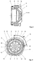
- this is provided with a plurality of rib-shaped radially extending driving 7 (see in particular Figures 2 and 4 ).
- the screw lock consists of a radial adjusting locking mechanism.
- the locking screw 5 is provided on its circumference with a plurality of locking levers 9, which via radial spokes 10 each in the region of one end of the locking lever 9 are connected to a central piece 11 of the locking screw.
- the radial spokes 10 may of course also be part of the rib-shaped entrainment 7.
- four locking lever 9 are arranged distributed over the circumference. Of course, however, other numbers are possible within the scope of the invention.
- the locking lever 9 are provided with locking lugs 12 at their remote from the spokes 10 free ends.
- the locking lugs 12 of the locking lever 9 engage in a toothing geometry 13 in the gear housing 2 (see in particular the enlarged view of the tooth geometry in the Fig. 6 ).
- the locking lever 9 When screwing the locking screw 5 in the gear housing 2, the locking lever 9 are deflected via bevels 18 in the gear housing 2 radially and snap on reaching the predetermined torque in tooth gaps 14 of the tooth geometry 13. A reverse rotation of the locking screw 5 is prevented by the saw-shaped contour of the tooth geometry 13.
- the latching lugs 9 are supported on contact surfaces 15 in the toothing gaps 14 of the toothing geometry 13.
- the locking lugs 9 can also be deflected axially if necessary and engage correspondingly in Vernierungslücken the tooth geometry in the bore of the housing.
- the locking lever angle division 16 is carried out asymmetrically (see Fig. 4 ). Accordingly, the toothing geometry 13 is executed in the gear housing 2 with the smallest possible angular pitch 17. In this way, a secure engagement of at least two locking lugs 12 regardless of the angle of rotation is always guaranteed. An asymmetry leads to a higher resolution or a greater probability of locking in the sense of a vernier effect.
- asymmetric locking lever angle division 16 is meant that the locking lever are not distributed uniformly over the circumference. So z. B. four locking levers instead of exactly four times 90 ° different angle divisions and different lengths can be provided. If then a small angular pitch 17 between the individual tooth gaps 14 (see Fig. 6 ) with z. B. 15 ° selected, it is achieved by the asymmetric Rasthebelwinkel Vietnamese 16 that in any case a secure engagement about every 4 ° is possible (based on the current application).
- the locking screw 5 in training of a plastic body may for example be formed of a fiber-reinforced thermoplastic injection molded part, which is characterized by a temperature-resistant behavior.
- the expansion behavior of the plastic body is determined by a temperature change through the material and the fiber orientation.
- the fibers are designed so that they run in the direction of the expected greater extent.
- the locking lever 9 can be used from high-strength plastics with a low elongation at break.
- the thread of the plastic body of the locking screw 5 may be designed as a metric tip thread, wherein the pitch diameter of the thread is designed so that only a small thread play is present.
- the internal teeth in the gear housing 2 and also the toothing geometry 13 can be finished cast. If necessary, a small tolerance can also be realized by means of a control machining of the toothing geometry 13 in the housing 2.
Landscapes
- Engineering & Computer Science (AREA)
- General Engineering & Computer Science (AREA)
- Mechanical Engineering (AREA)
- Chemical & Material Sciences (AREA)
- Combustion & Propulsion (AREA)
- Transportation (AREA)
- Power Steering Mechanism (AREA)
- Injection Moulding Of Plastics Or The Like (AREA)
- Gears, Cams (AREA)
- Mounting Of Bearings Or Others (AREA)
- Rolling Contact Bearings (AREA)
- Gear Transmission (AREA)
Applications Claiming Priority (2)
| Application Number | Priority Date | Filing Date | Title |
|---|---|---|---|
| DE102011051961A DE102011051961A1 (de) | 2011-07-20 | 2011-07-20 | Vorrichtung zur Lagesicherung einer Einheit |
| PCT/EP2012/063571 WO2013010873A1 (de) | 2011-07-20 | 2012-07-11 | Vorrichtung zur lagesicherung einer einheit |
Publications (2)
| Publication Number | Publication Date |
|---|---|
| EP2734742A1 EP2734742A1 (de) | 2014-05-28 |
| EP2734742B1 true EP2734742B1 (de) | 2016-08-17 |
Family
ID=46508059
Family Applications (1)
| Application Number | Title | Priority Date | Filing Date |
|---|---|---|---|
| EP12734942.1A Active EP2734742B1 (de) | 2011-07-20 | 2012-07-11 | Vorrichtung zur lagesicherung einer einheit |
Country Status (7)
Cited By (1)
| Publication number | Priority date | Publication date | Assignee | Title |
|---|---|---|---|---|
| DE102019213117A1 (de) * | 2019-08-30 | 2021-03-04 | Zf Friedrichshafen Ag | Sicherungsvorrichtung einer Schraubverbindung einer Mutter auf einer Welle |
Families Citing this family (10)
| Publication number | Priority date | Publication date | Assignee | Title |
|---|---|---|---|---|
| KR102096989B1 (ko) * | 2013-11-04 | 2020-04-03 | 현대모비스 주식회사 | 차량의 요크유격보상장치 |
| US9879771B2 (en) | 2015-03-27 | 2018-01-30 | Amarillo Gear Company Llc | Dry well shaft assembly |
| US10514064B2 (en) * | 2015-05-22 | 2019-12-24 | The Timken Company | Bearing package and installation tool |
| EP3365960A4 (en) | 2015-10-22 | 2019-06-19 | Nidec Motor Corporation | ELECTRIC MOTOR |
| DE102015118887A1 (de) | 2015-11-04 | 2017-05-04 | Getrag Getriebe- Und Zahnradfabrik Hermann Hagenmeyer Gmbh & Cie Kg | Axialsicherungsanordnung und Axialsicherungsverfahren |
| CN106122237A (zh) * | 2016-08-23 | 2016-11-16 | 瑞安市威孚标准件有限公司 | 自锁紧螺钉 |
| DE102018104608A1 (de) * | 2018-02-28 | 2019-08-29 | Trw Automotive Gmbh | Lenksystem-Wellenlagerungsbaugruppe, Lenksystem sowie Verfahren zur Herstellung eines Lenksystems |
| CN110513396B (zh) * | 2019-09-04 | 2020-11-17 | 安徽省含山县林头振皖铸造厂 | 电机转轴轴承的绝缘式密封端盖 |
| CN112594286A (zh) * | 2020-11-30 | 2021-04-02 | 河南航天精工制造有限公司 | 一种自锁螺套 |
| CN113944680B (zh) * | 2021-10-18 | 2022-08-05 | 北京微纳星空科技有限公司 | 一种棘轮锁紧机构 |
Family Cites Families (32)
| Publication number | Priority date | Publication date | Assignee | Title |
|---|---|---|---|---|
| US3650040A (en) * | 1969-08-28 | 1972-03-21 | Louis D Statham | Film dryer |
| DE2741904A1 (de) * | 1977-09-17 | 1979-03-29 | Klaus Boetzkes | Spundabdichtung fuer bierfaesser |
| AU550194B2 (en) * | 1981-12-17 | 1986-03-06 | Bishop Steering Technology Limited | Rack and pinion steering gear |
| US4403933A (en) * | 1982-04-14 | 1983-09-13 | Fischer & Porter Company | Apparatus for injection-molding a liner onto a metal spool |
| US4717183A (en) * | 1982-07-07 | 1988-01-05 | Vetco Offshore Industries, Inc. | Conical thread configuration for rapid make-up connection |
| US4742883A (en) * | 1986-09-29 | 1988-05-10 | Ford Motor Company | Pinion ball bearings with preload adjustment for power rack and pinion steering gears |
| DE3935753A1 (de) * | 1988-11-12 | 1990-05-17 | Volkswagen Ag | Arretiervorrichtung |
| US5234259A (en) * | 1990-09-07 | 1993-08-10 | Bridgestone Corporation | Resin wheel with more than two independently molded parts |
| SE504338C2 (sv) * | 1994-06-07 | 1997-01-13 | Sandvik Ab | Skärplatta |
| SE509218C2 (sv) * | 1994-08-29 | 1998-12-21 | Sandvik Ab | Skaftverktyg |
| JPH08145038A (ja) * | 1994-11-24 | 1996-06-04 | Koizumi Sangyo Kk | シールワッシャ付きのナット |
| US5482132A (en) * | 1995-05-26 | 1996-01-09 | Birsching; Joel E. | Pinion head for power steering gear |
| AT403402B (de) * | 1995-11-06 | 1998-02-25 | Mark Rudolf | Befestigungselement |
| US5713706A (en) * | 1995-12-19 | 1998-02-03 | Shur-Lok Corporation | Plastic composite fastener for self-cutting and frictional welding |
| US5690143A (en) * | 1996-04-08 | 1997-11-25 | General Motors Corporation | Valve for power steering gear |
| AU4221499A (en) | 1999-05-28 | 2000-12-18 | Aim Group, Llc, The | Locking nut, bolt and clip systems and assemblies |
| JP2003226246A (ja) * | 2002-02-06 | 2003-08-12 | Koyo Seiko Co Ltd | ラックピニオン式舵取装置 |
| FR2853383B1 (fr) | 2003-04-07 | 2005-05-27 | Koyo Steering Europe Kse | Dispositif de rattrapage du jeu radial d'un poussoir de direction a cremaillere |
| EP1489263B1 (de) * | 2003-06-19 | 2007-02-14 | ABB Turbo Systems AG | Wellen-/Nabenverbindung eines Turboladers |
| US20050220569A1 (en) * | 2004-04-01 | 2005-10-06 | Joseph Dryer | Latching quick-connect connector |
| DE102004021484B4 (de) * | 2004-04-30 | 2018-11-29 | Böllhoff Verbindungstechnik GmbH | Verfahren zum Herstellen einer Verbindungsanordnung |
| CA2573137C (en) * | 2004-07-07 | 2016-11-15 | Pyrotek Inc. | Molten metal pump |
| DE202005010873U1 (de) * | 2005-07-11 | 2005-09-22 | Böllhoff Verbindungstechnik GmbH | Toleranzausgleichseinrichtung aus Kunststoff |
| WO2007013173A1 (ja) * | 2005-07-29 | 2007-02-01 | Jtekt Corporation | ねじの緩み防止のための方法および構造ならびに雄ねじの製造方法 |
| US20080044659A1 (en) * | 2005-12-15 | 2008-02-21 | Polystrand, Inc. | Composite laminate and method of manufacture |
| CN201031869Y (zh) * | 2007-03-21 | 2008-03-05 | 张平 | 棘轮式防盗螺母 |
| WO2009001421A1 (ja) | 2007-06-25 | 2008-12-31 | Miraial Co., Ltd. | ボルトの緩み止め機構 |
| JP5147066B2 (ja) * | 2008-12-03 | 2013-02-20 | 内山工業株式会社 | 密封構造 |
| DE112010003770T5 (de) * | 2009-09-25 | 2012-10-11 | Mclaren Performance Technologies, Inc. | Verkörnte Mutter und Flansch zur Getriebeunterstützung |
| DE102010008404A1 (de) | 2010-02-09 | 2011-08-11 | MAHLE International GmbH, 70376 | Verliersicherung |
| DE102011051960A1 (de) * | 2011-07-20 | 2013-01-24 | Zf Lenksysteme Gmbh | Vorrichtung zum Lösen einer Sicherungsschraube für eine Einheit in einem Gehäuse |
| US9010208B2 (en) * | 2012-07-13 | 2015-04-21 | Trw Automotive U.S. Llc | Yoke assembly for a rack and pinion steering gear and method for producing the same |
-
2011
- 2011-07-20 DE DE102011051961A patent/DE102011051961A1/de not_active Withdrawn
-
2012
- 2012-07-11 WO PCT/EP2012/063571 patent/WO2013010873A1/de active Application Filing
- 2012-07-11 CN CN201280035421.7A patent/CN103688067B/zh active Active
- 2012-07-11 JP JP2014520609A patent/JP6017556B2/ja not_active Expired - Fee Related
- 2012-07-11 US US14/128,896 patent/US9086090B2/en active Active
- 2012-07-11 EP EP12734942.1A patent/EP2734742B1/de active Active
- 2012-07-11 HU HUE12734942A patent/HUE031732T2/en unknown
Cited By (1)
| Publication number | Priority date | Publication date | Assignee | Title |
|---|---|---|---|---|
| DE102019213117A1 (de) * | 2019-08-30 | 2021-03-04 | Zf Friedrichshafen Ag | Sicherungsvorrichtung einer Schraubverbindung einer Mutter auf einer Welle |
Also Published As
| Publication number | Publication date |
|---|---|
| DE102011051961A1 (de) | 2013-01-24 |
| EP2734742A1 (de) | 2014-05-28 |
| US9086090B2 (en) | 2015-07-21 |
| JP6017556B2 (ja) | 2016-11-02 |
| CN103688067A (zh) | 2014-03-26 |
| WO2013010873A1 (de) | 2013-01-24 |
| HUE031732T2 (en) | 2017-07-28 |
| CN103688067B (zh) | 2016-01-20 |
| US20140126976A1 (en) | 2014-05-08 |
| JP2014521042A (ja) | 2014-08-25 |
Similar Documents
| Publication | Publication Date | Title |
|---|---|---|
| EP2734742B1 (de) | Vorrichtung zur lagesicherung einer einheit | |
| EP2734335B1 (de) | Vorrichtung zum lösen einer sicherungsschraube für eine einheit in einem gehäuse | |
| EP3717786B1 (de) | Toleranzausgleichsanordnung mit klemmsicherung | |
| EP3573874B1 (de) | Motorisch verstellbare lenksäule für ein kraftfahrzeug und verstellantrieb für eine lenksäule | |
| EP3475148B1 (de) | Kugelgewindetrieb einer elektromechanischen servolenkung mit integriertem schrägkugellager und kompensation unterschiedlicher wärmeausdehnungen | |
| DE102012016949A1 (de) | Nabe für wenigstens teilweise muskelbetriebene Fahrzeuge | |
| DE102018212202B4 (de) | Getrieberad für einen Verstellantrieb, Verstellantrieb für eine Lenksäule und Lenksäule für ein Kraftfahrzeug | |
| DE102016007542A1 (de) | Kugelgewindetrieb einer elektromechanischen Servolenkung mit Umlenkkörper für eine Kugelrückführung | |
| DE102006059946A1 (de) | Zahnriemenrad | |
| DE102013010360A1 (de) | Doppelritzel-Lenkgetriebe mit Elektromotor | |
| DE102021100676A1 (de) | Halteelement zum Befestigen eines Anbauteils | |
| WO2017220715A1 (de) | Kugelgewindetrieb einer elektromechanischen servolenkung mit integriertem schrägkugellager | |
| DE102013010362A1 (de) | Doppelritzel-Lenkgetriebe mit Hohlwellenmotor | |
| EP2572945A1 (de) | Elektrische Lenkverriegelung | |
| DE102019133406A1 (de) | Schubstangenführungsbaugruppe, Lenkaktuator sowie Verfahren zur Herstellung einer Schubstangenführungsbaugruppe | |
| DE102017219395A1 (de) | Vorspanneinrichtung | |
| DE102008028371A1 (de) | Toleranzring | |
| EP3728899A1 (de) | Schneckenrad für ein schneckenradgetriebe einer kraftfahrzeuglenkung mit einem zwischen einer nabe und einem zahnkranz eingespritzten trägerring | |
| EP2201386B1 (de) | Kupplungsvorrichtung, insbesondere für eine sensoreinrichtung | |
| EP2652292B1 (de) | Ventil | |
| DE19906693C1 (de) | Stellantrieb, insbesondere für Heizungs-, Lüftungs-, oder Klimaklappen im Kfz | |
| EP3233607B1 (de) | Arretiervorrichtung | |
| DE102014212367A1 (de) | Lenkgetriebe mit einer Lenkeingangswelle und einer über einen Torsionsstab mit der Lenkeingangswelle gekoppelten Ritzelwelle | |
| WO2019174963A1 (de) | Schraubradgetriebe für eine elektromechanische servolenkung mit einem asymmetrisch vorgespannten festlager | |
| EP4091786B1 (de) | Schraubverbindung |
Legal Events
| Date | Code | Title | Description |
|---|---|---|---|
| PUAI | Public reference made under article 153(3) epc to a published international application that has entered the european phase |
Free format text: ORIGINAL CODE: 0009012 |
|
| 17P | Request for examination filed |
Effective date: 20131205 |
|
| AK | Designated contracting states |
Kind code of ref document: A1 Designated state(s): AL AT BE BG CH CY CZ DE DK EE ES FI FR GB GR HR HU IE IS IT LI LT LU LV MC MK MT NL NO PL PT RO RS SE SI SK SM TR |
|
| DAX | Request for extension of the european patent (deleted) | ||
| RAP1 | Party data changed (applicant data changed or rights of an application transferred) |
Owner name: ROBERT BOSCH AUTOMOTIVE STEERING GMBH |
|
| GRAP | Despatch of communication of intention to grant a patent |
Free format text: ORIGINAL CODE: EPIDOSNIGR1 |
|
| INTG | Intention to grant announced |
Effective date: 20160523 |
|
| GRAS | Grant fee paid |
Free format text: ORIGINAL CODE: EPIDOSNIGR3 |
|
| GRAA | (expected) grant |
Free format text: ORIGINAL CODE: 0009210 |
|
| AK | Designated contracting states |
Kind code of ref document: B1 Designated state(s): AL AT BE BG CH CY CZ DE DK EE ES FI FR GB GR HR HU IE IS IT LI LT LU LV MC MK MT NL NO PL PT RO RS SE SI SK SM TR |
|
| REG | Reference to a national code |
Ref country code: GB Ref legal event code: FG4D Free format text: NOT ENGLISH |
|
| REG | Reference to a national code |
Ref country code: CH Ref legal event code: EP |
|
| REG | Reference to a national code |
Ref country code: IE Ref legal event code: FG4D Free format text: LANGUAGE OF EP DOCUMENT: GERMAN |
|
| REG | Reference to a national code |
Ref country code: AT Ref legal event code: REF Ref document number: 821409 Country of ref document: AT Kind code of ref document: T Effective date: 20160915 |
|
| REG | Reference to a national code |
Ref country code: DE Ref legal event code: R096 Ref document number: 502012007985 Country of ref document: DE |
|
| REG | Reference to a national code |
Ref country code: NL Ref legal event code: MP Effective date: 20160817 |
|
| REG | Reference to a national code |
Ref country code: LT Ref legal event code: MG4D |
|
| PG25 | Lapsed in a contracting state [announced via postgrant information from national office to epo] |
Ref country code: RS Free format text: LAPSE BECAUSE OF FAILURE TO SUBMIT A TRANSLATION OF THE DESCRIPTION OR TO PAY THE FEE WITHIN THE PRESCRIBED TIME-LIMIT Effective date: 20160817 Ref country code: HR Free format text: LAPSE BECAUSE OF FAILURE TO SUBMIT A TRANSLATION OF THE DESCRIPTION OR TO PAY THE FEE WITHIN THE PRESCRIBED TIME-LIMIT Effective date: 20160817 Ref country code: LT Free format text: LAPSE BECAUSE OF FAILURE TO SUBMIT A TRANSLATION OF THE DESCRIPTION OR TO PAY THE FEE WITHIN THE PRESCRIBED TIME-LIMIT Effective date: 20160817 Ref country code: NL Free format text: LAPSE BECAUSE OF FAILURE TO SUBMIT A TRANSLATION OF THE DESCRIPTION OR TO PAY THE FEE WITHIN THE PRESCRIBED TIME-LIMIT Effective date: 20160817 Ref country code: IT Free format text: LAPSE BECAUSE OF FAILURE TO SUBMIT A TRANSLATION OF THE DESCRIPTION OR TO PAY THE FEE WITHIN THE PRESCRIBED TIME-LIMIT Effective date: 20160817 Ref country code: FI Free format text: LAPSE BECAUSE OF FAILURE TO SUBMIT A TRANSLATION OF THE DESCRIPTION OR TO PAY THE FEE WITHIN THE PRESCRIBED TIME-LIMIT Effective date: 20160817 Ref country code: NO Free format text: LAPSE BECAUSE OF FAILURE TO SUBMIT A TRANSLATION OF THE DESCRIPTION OR TO PAY THE FEE WITHIN THE PRESCRIBED TIME-LIMIT Effective date: 20161117 |
|
| PG25 | Lapsed in a contracting state [announced via postgrant information from national office to epo] |
Ref country code: SE Free format text: LAPSE BECAUSE OF FAILURE TO SUBMIT A TRANSLATION OF THE DESCRIPTION OR TO PAY THE FEE WITHIN THE PRESCRIBED TIME-LIMIT Effective date: 20160817 Ref country code: PL Free format text: LAPSE BECAUSE OF FAILURE TO SUBMIT A TRANSLATION OF THE DESCRIPTION OR TO PAY THE FEE WITHIN THE PRESCRIBED TIME-LIMIT Effective date: 20160817 Ref country code: GR Free format text: LAPSE BECAUSE OF FAILURE TO SUBMIT A TRANSLATION OF THE DESCRIPTION OR TO PAY THE FEE WITHIN THE PRESCRIBED TIME-LIMIT Effective date: 20161118 Ref country code: PT Free format text: LAPSE BECAUSE OF FAILURE TO SUBMIT A TRANSLATION OF THE DESCRIPTION OR TO PAY THE FEE WITHIN THE PRESCRIBED TIME-LIMIT Effective date: 20161219 Ref country code: LV Free format text: LAPSE BECAUSE OF FAILURE TO SUBMIT A TRANSLATION OF THE DESCRIPTION OR TO PAY THE FEE WITHIN THE PRESCRIBED TIME-LIMIT Effective date: 20160817 Ref country code: ES Free format text: LAPSE BECAUSE OF FAILURE TO SUBMIT A TRANSLATION OF THE DESCRIPTION OR TO PAY THE FEE WITHIN THE PRESCRIBED TIME-LIMIT Effective date: 20160817 |
|
| PG25 | Lapsed in a contracting state [announced via postgrant information from national office to epo] |
Ref country code: RO Free format text: LAPSE BECAUSE OF FAILURE TO SUBMIT A TRANSLATION OF THE DESCRIPTION OR TO PAY THE FEE WITHIN THE PRESCRIBED TIME-LIMIT Effective date: 20160817 Ref country code: EE Free format text: LAPSE BECAUSE OF FAILURE TO SUBMIT A TRANSLATION OF THE DESCRIPTION OR TO PAY THE FEE WITHIN THE PRESCRIBED TIME-LIMIT Effective date: 20160817 |
|
| REG | Reference to a national code |
Ref country code: DE Ref legal event code: R097 Ref document number: 502012007985 Country of ref document: DE |
|
| PG25 | Lapsed in a contracting state [announced via postgrant information from national office to epo] |
Ref country code: SK Free format text: LAPSE BECAUSE OF FAILURE TO SUBMIT A TRANSLATION OF THE DESCRIPTION OR TO PAY THE FEE WITHIN THE PRESCRIBED TIME-LIMIT Effective date: 20160817 Ref country code: BG Free format text: LAPSE BECAUSE OF FAILURE TO SUBMIT A TRANSLATION OF THE DESCRIPTION OR TO PAY THE FEE WITHIN THE PRESCRIBED TIME-LIMIT Effective date: 20161117 Ref country code: SM Free format text: LAPSE BECAUSE OF FAILURE TO SUBMIT A TRANSLATION OF THE DESCRIPTION OR TO PAY THE FEE WITHIN THE PRESCRIBED TIME-LIMIT Effective date: 20160817 Ref country code: CZ Free format text: LAPSE BECAUSE OF FAILURE TO SUBMIT A TRANSLATION OF THE DESCRIPTION OR TO PAY THE FEE WITHIN THE PRESCRIBED TIME-LIMIT Effective date: 20160817 Ref country code: DK Free format text: LAPSE BECAUSE OF FAILURE TO SUBMIT A TRANSLATION OF THE DESCRIPTION OR TO PAY THE FEE WITHIN THE PRESCRIBED TIME-LIMIT Effective date: 20160817 |
|
| PLBE | No opposition filed within time limit |
Free format text: ORIGINAL CODE: 0009261 |
|
| STAA | Information on the status of an ep patent application or granted ep patent |
Free format text: STATUS: NO OPPOSITION FILED WITHIN TIME LIMIT |
|
| REG | Reference to a national code |
Ref country code: FR Ref legal event code: PLFP Year of fee payment: 6 |
|
| 26N | No opposition filed |
Effective date: 20170518 |
|
| REG | Reference to a national code |
Ref country code: HU Ref legal event code: AG4A Ref document number: E031732 Country of ref document: HU |
|
| PG25 | Lapsed in a contracting state [announced via postgrant information from national office to epo] |
Ref country code: SI Free format text: LAPSE BECAUSE OF FAILURE TO SUBMIT A TRANSLATION OF THE DESCRIPTION OR TO PAY THE FEE WITHIN THE PRESCRIBED TIME-LIMIT Effective date: 20160817 |
|
| REG | Reference to a national code |
Ref country code: CH Ref legal event code: PL |
|
| GBPC | Gb: european patent ceased through non-payment of renewal fee |
Effective date: 20170711 |
|
| REG | Reference to a national code |
Ref country code: IE Ref legal event code: MM4A |
|
| PG25 | Lapsed in a contracting state [announced via postgrant information from national office to epo] |
Ref country code: IE Free format text: LAPSE BECAUSE OF NON-PAYMENT OF DUE FEES Effective date: 20170711 Ref country code: CH Free format text: LAPSE BECAUSE OF NON-PAYMENT OF DUE FEES Effective date: 20170731 Ref country code: GB Free format text: LAPSE BECAUSE OF NON-PAYMENT OF DUE FEES Effective date: 20170711 Ref country code: LI Free format text: LAPSE BECAUSE OF NON-PAYMENT OF DUE FEES Effective date: 20170731 |
|
| REG | Reference to a national code |
Ref country code: BE Ref legal event code: MM Effective date: 20170731 |
|
| PG25 | Lapsed in a contracting state [announced via postgrant information from national office to epo] |
Ref country code: LU Free format text: LAPSE BECAUSE OF NON-PAYMENT OF DUE FEES Effective date: 20170711 |
|
| REG | Reference to a national code |
Ref country code: FR Ref legal event code: PLFP Year of fee payment: 7 |
|
| PG25 | Lapsed in a contracting state [announced via postgrant information from national office to epo] |
Ref country code: BE Free format text: LAPSE BECAUSE OF NON-PAYMENT OF DUE FEES Effective date: 20170731 |
|
| REG | Reference to a national code |
Ref country code: AT Ref legal event code: MM01 Ref document number: 821409 Country of ref document: AT Kind code of ref document: T Effective date: 20170711 |
|
| PG25 | Lapsed in a contracting state [announced via postgrant information from national office to epo] |
Ref country code: MT Free format text: LAPSE BECAUSE OF FAILURE TO SUBMIT A TRANSLATION OF THE DESCRIPTION OR TO PAY THE FEE WITHIN THE PRESCRIBED TIME-LIMIT Effective date: 20160817 |
|
| PG25 | Lapsed in a contracting state [announced via postgrant information from national office to epo] |
Ref country code: AL Free format text: LAPSE BECAUSE OF FAILURE TO SUBMIT A TRANSLATION OF THE DESCRIPTION OR TO PAY THE FEE WITHIN THE PRESCRIBED TIME-LIMIT Effective date: 20160817 |
|
| PG25 | Lapsed in a contracting state [announced via postgrant information from national office to epo] |
Ref country code: AT Free format text: LAPSE BECAUSE OF NON-PAYMENT OF DUE FEES Effective date: 20170711 |
|
| PG25 | Lapsed in a contracting state [announced via postgrant information from national office to epo] |
Ref country code: MC Free format text: LAPSE BECAUSE OF FAILURE TO SUBMIT A TRANSLATION OF THE DESCRIPTION OR TO PAY THE FEE WITHIN THE PRESCRIBED TIME-LIMIT Effective date: 20160817 |
|
| PG25 | Lapsed in a contracting state [announced via postgrant information from national office to epo] |
Ref country code: CY Free format text: LAPSE BECAUSE OF NON-PAYMENT OF DUE FEES Effective date: 20160817 |
|
| PG25 | Lapsed in a contracting state [announced via postgrant information from national office to epo] |
Ref country code: MK Free format text: LAPSE BECAUSE OF FAILURE TO SUBMIT A TRANSLATION OF THE DESCRIPTION OR TO PAY THE FEE WITHIN THE PRESCRIBED TIME-LIMIT Effective date: 20160817 |
|
| PG25 | Lapsed in a contracting state [announced via postgrant information from national office to epo] |
Ref country code: TR Free format text: LAPSE BECAUSE OF FAILURE TO SUBMIT A TRANSLATION OF THE DESCRIPTION OR TO PAY THE FEE WITHIN THE PRESCRIBED TIME-LIMIT Effective date: 20160817 |
|
| REG | Reference to a national code |
Ref country code: DE Ref legal event code: R081 Ref document number: 502012007985 Country of ref document: DE Owner name: ROBERT BOSCH GMBH, DE Free format text: FORMER OWNER: ROBERT BOSCH AUTOMOTIVE STEERING GMBH, 73527 SCHWAEBISCH GMUEND, DE |
|
| PG25 | Lapsed in a contracting state [announced via postgrant information from national office to epo] |
Ref country code: IS Free format text: LAPSE BECAUSE OF FAILURE TO SUBMIT A TRANSLATION OF THE DESCRIPTION OR TO PAY THE FEE WITHIN THE PRESCRIBED TIME-LIMIT Effective date: 20161217 |
|
| PGFP | Annual fee paid to national office [announced via postgrant information from national office to epo] |
Ref country code: FR Payment date: 20210721 Year of fee payment: 10 |
|
| PGFP | Annual fee paid to national office [announced via postgrant information from national office to epo] |
Ref country code: HU Payment date: 20210705 Year of fee payment: 10 |
|
| PG25 | Lapsed in a contracting state [announced via postgrant information from national office to epo] |
Ref country code: FR Free format text: LAPSE BECAUSE OF NON-PAYMENT OF DUE FEES Effective date: 20220731 |
|
| PG25 | Lapsed in a contracting state [announced via postgrant information from national office to epo] |
Ref country code: HU Free format text: LAPSE BECAUSE OF NON-PAYMENT OF DUE FEES Effective date: 20220712 |
|
| PGFP | Annual fee paid to national office [announced via postgrant information from national office to epo] |
Ref country code: DE Payment date: 20240919 Year of fee payment: 13 |