EP2733432A2 - Vorrichtung zur Steuerung einer Klimaanlage - Google Patents
Vorrichtung zur Steuerung einer Klimaanlage Download PDFInfo
- Publication number
- EP2733432A2 EP2733432A2 EP13192330.2A EP13192330A EP2733432A2 EP 2733432 A2 EP2733432 A2 EP 2733432A2 EP 13192330 A EP13192330 A EP 13192330A EP 2733432 A2 EP2733432 A2 EP 2733432A2
- Authority
- EP
- European Patent Office
- Prior art keywords
- unit
- data
- control unit
- air conditioner
- information
- Prior art date
- Legal status (The legal status is an assumption and is not a legal conclusion. Google has not performed a legal analysis and makes no representation as to the accuracy of the status listed.)
- Withdrawn
Links
- 238000004891 communication Methods 0.000 claims description 26
- 238000012544 monitoring process Methods 0.000 claims description 17
- 238000003745 diagnosis Methods 0.000 claims description 15
- 230000008859 change Effects 0.000 claims description 9
- 238000000034 method Methods 0.000 claims description 5
- 230000005540 biological transmission Effects 0.000 claims description 4
- 230000002159 abnormal effect Effects 0.000 claims 1
- 238000009434 installation Methods 0.000 claims 1
- 230000008901 benefit Effects 0.000 abstract description 4
- 230000006870 function Effects 0.000 description 6
- 239000003086 colorant Substances 0.000 description 4
- 238000001816 cooling Methods 0.000 description 4
- 238000007689 inspection Methods 0.000 description 4
- 238000004378 air conditioning Methods 0.000 description 3
- 238000010438 heat treatment Methods 0.000 description 3
- 230000002093 peripheral effect Effects 0.000 description 3
- 230000000007 visual effect Effects 0.000 description 3
- 238000004140 cleaning Methods 0.000 description 2
- 238000010586 diagram Methods 0.000 description 2
- 238000001704 evaporation Methods 0.000 description 2
- 230000008020 evaporation Effects 0.000 description 2
- 239000004973 liquid crystal related substance Substances 0.000 description 2
- 230000008569 process Effects 0.000 description 2
- 238000012545 processing Methods 0.000 description 2
- 239000003507 refrigerant Substances 0.000 description 2
- 108010025037 T140 peptide Proteins 0.000 description 1
- 238000004364 calculation method Methods 0.000 description 1
- 230000006835 compression Effects 0.000 description 1
- 238000007906 compression Methods 0.000 description 1
- 238000013500 data storage Methods 0.000 description 1
- 238000007599 discharging Methods 0.000 description 1
- 230000000694 effects Effects 0.000 description 1
- 230000005611 electricity Effects 0.000 description 1
- 239000012530 fluid Substances 0.000 description 1
- 230000010365 information processing Effects 0.000 description 1
- 238000012986 modification Methods 0.000 description 1
- 230000004048 modification Effects 0.000 description 1
- 229920000642 polymer Polymers 0.000 description 1
- 230000003252 repetitive effect Effects 0.000 description 1
- 239000007787 solid Substances 0.000 description 1
- 230000003068 static effect Effects 0.000 description 1
- 238000010257 thawing Methods 0.000 description 1
- 239000010409 thin film Substances 0.000 description 1
Images


Classifications
-
- F—MECHANICAL ENGINEERING; LIGHTING; HEATING; WEAPONS; BLASTING
- F24—HEATING; RANGES; VENTILATING
- F24F—AIR-CONDITIONING; AIR-HUMIDIFICATION; VENTILATION; USE OF AIR CURRENTS FOR SCREENING
- F24F11/00—Control or safety arrangements
- F24F11/30—Control or safety arrangements for purposes related to the operation of the system, e.g. for safety or monitoring
- F24F11/32—Responding to malfunctions or emergencies
- F24F11/38—Failure diagnosis
-
- F—MECHANICAL ENGINEERING; LIGHTING; HEATING; WEAPONS; BLASTING
- F24—HEATING; RANGES; VENTILATING
- F24F—AIR-CONDITIONING; AIR-HUMIDIFICATION; VENTILATION; USE OF AIR CURRENTS FOR SCREENING
- F24F11/00—Control or safety arrangements
- F24F11/50—Control or safety arrangements characterised by user interfaces or communication
- F24F11/52—Indication arrangements, e.g. displays
-
- F—MECHANICAL ENGINEERING; LIGHTING; HEATING; WEAPONS; BLASTING
- F24—HEATING; RANGES; VENTILATING
- F24F—AIR-CONDITIONING; AIR-HUMIDIFICATION; VENTILATION; USE OF AIR CURRENTS FOR SCREENING
- F24F11/00—Control or safety arrangements
- F24F11/50—Control or safety arrangements characterised by user interfaces or communication
- F24F11/54—Control or safety arrangements characterised by user interfaces or communication using one central controller connected to several sub-controllers
-
- F—MECHANICAL ENGINEERING; LIGHTING; HEATING; WEAPONS; BLASTING
- F25—REFRIGERATION OR COOLING; COMBINED HEATING AND REFRIGERATION SYSTEMS; HEAT PUMP SYSTEMS; MANUFACTURE OR STORAGE OF ICE; LIQUEFACTION SOLIDIFICATION OF GASES
- F25B—REFRIGERATION MACHINES, PLANTS OR SYSTEMS; COMBINED HEATING AND REFRIGERATION SYSTEMS; HEAT PUMP SYSTEMS
- F25B49/00—Arrangement or mounting of control or safety devices
-
- F—MECHANICAL ENGINEERING; LIGHTING; HEATING; WEAPONS; BLASTING
- F24—HEATING; RANGES; VENTILATING
- F24F—AIR-CONDITIONING; AIR-HUMIDIFICATION; VENTILATION; USE OF AIR CURRENTS FOR SCREENING
- F24F2110/00—Control inputs relating to air properties
Definitions
- the present invention relates to an apparatus for controlling an air conditioner. More specifically, the present invention relates to an apparatus for controlling an air conditioner which receives operation and state information on an air conditioner and displays cycle information on the air conditioner.
- control apparatus controls a domestic appliance, such as TV, video, audio, air conditioner, cable broadcasting converter, a satellite broadcasting converter, and fan.
- a domestic appliance such as TV, video, audio, air conditioner, cable broadcasting converter, a satellite broadcasting converter, and fan.
- control apparatus may control various domestic appliances by wireless transmission of a control frequency or cable communication, remotely.
- the control apparatus may be a specialized apparatus to a particular domestic appliance, or a computer having software loaded thereon for controlling a particular domestic appliance.
- the control apparatus may be applied to the air conditioner.
- a multi-type air conditioner used in a large sized building which requires a plurality of indoor units, such as a building, has one outdoor unit connected to the plurality of indoor units.
- the indoor units are installed in respective rooms for air conditioning of the rooms, an effect may be obtained, in which a plurality of air conditioners are installed to the building.
- the multi-type air conditioner is provided with a central control unit configured to control and monitor a state of the air conditioner in a position of a user to enable to monitor a temperature, an operation mode, and whether the air conditioner has something wrong or not, if the air conditioner has something wrong, a state of the air conditioner having something wrong is required to be inspected based, not on a simple state data, but on various data on each unit of the air conditioner for proper inspection of the state.
- the present invention has been made in an effort to solve the aforementioned problems, and it is an object of the present invention to provide an apparatus for controlling an air conditioner, in which a cycle view is displayed for making easy notice on cycle information on the air conditioner based on data from the air conditioner, and determining a state of the air conditioner easily to enable to take a countermeasure.
- a control apparatus includes a control unit connected to one of a plurality of equipped apparatuses for monitoring and controlling the plurality of equipped apparatuses, wherein the control unit receives a cycle data which enables trouble diagnosis on the plurality of equipped apparatuses from the equipped apparatus connected thereto thus in real time, displays the cycle data on the plurality of equipped apparatuses on a frame, and changes the cycle data displayed thus if the data on the plurality of equipped apparatuses is changed.
- the control apparatus for an air conditioner of the present invention permits the user to notice trouble of the air conditioner instantly because the control apparatus stores and manages the data from the air conditioner, and displays the data visually and changes of the operation state of the air conditioner with time enabling to determine the state of the air conditioner easily, and permits to improve user's convenience significantly because the control apparatus displays the cycle data on the air conditioner in an image or a code matched to the units of the air conditioner enabling to determine a flow of an entire structure and general operation of the air conditioner.
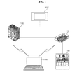
- FIGS. 1 to 3 are schematic views each illustrating an air conditioner system including a control apparatus in accordance with a preferred embodiment of the present invention.
- the air conditioner system in accordance with a preferred embodiment of the present invention includes an indoor unit 130, an outdoor unit 120, a central controller 110, a remote controller 140, and a control unit 150.
- the air conditioner system also includes a ventilating unit, a defrosting unit, a humidifying unit, a heater, and a showcase.
- the control unit 150 may be a microcomputer including software connected to the indoor unit 130 or the outdoor unit 120 with or without wire for controlling the indoor unit 130 or the outdoor unit 120.
- the remote controller 140 is connected to the indoor unit 130 or the outdoor unit 120 with, not limited to, wire for transmission of a control signal, but the remote controller 140 may also communicate with the indoor unit 130 or the outdoor unit 120 without wire.
- the central controller 110 is connected to the indoor unit 130 and the outdoor unit 120 to transmit/receive data thereto/therefrom for monitoring and controlling operation thereof.
- the central controller 110 includes input means for inputting an order thereto, and output means for displaying control data or information.
- the input means of the central controller 110 may include an input unit, such as a mechanical button, or a touch pad for sensing touch input in a broad sense.
- the output means of the central controller 110 may include a unit which generates a light, including a light source (A unit which emits a light, such as LED: Light Emitting Diode, OLED: Organic Light Emitting Diode, or so on).
- the central controller 110 may include a microprocessor which is able to process information, and transmits/receives a control signal in connection to information processing. As shown in FIG. 1 , the central controller 110 may be connected to the indoor unit 130 and the outdoor unit 120, and may communicate with the indoor unit 130 and the outdoor unit 120 with or without wire, but not limited to this.
- the central controller 110 may control the indoor unit 130 and the outdoor unit 120 individually, and the central controller 110 may control control of the indoor unit 130.
- the central controller 110 may make a central control locking for cutting off operation of the remote controller 140 which controls each of the plurality of indoor units 130.
- the central controller 110 may transmit a signal which limits input to the remote controller 140 which controls each of the indoor units 130 to the remote controller 140, the indoor unit 130 or the outdoor unit 120.
- the air conditioner being a room cooling/heating system which cools the room or heats the room by operation opposite to the room cooling by using repetitive operation of drawing warm air from the room, heat exchanging the warm air drawn thus with low temperature refrigerant, and discharging the air heat exchanged thus to the room, is an apparatus which forms a series of cycles with a compressor-a condenser-an expansion valve-an evaporator.
- the air conditioner is divided into the outdoor unit 120 installed outdoor mostly, and the indoor unit 130 installed indoor mostly, wherein the outdoor unit 120 may have the condenser and the compressor mounted thereto, and the indoor unit 130 may have the evaporator mounted thereto.
- the outdoor unit 120 and the indoor unit 130 may be connected to the central controller 110 for receiving a control signal.
- the plurality of indoor units 130 may be individually connected to the control unit 150 for receiving the control signal to make operation corresponding thereto.
- the outdoor unit 120 may transmit the data information requested thus. Depending on contents of the request from the control unit 150, contents of the data information to be transmitted may vary. For an example, the outdoor unit 120 may vary the data information to be transmitted with a requested time, but not limited only thereto.
- the outdoor unit 120 may include a storage medium (Not shown) for storing the data information.
- the outdoor unit 120 may store the data information including operation states periodically. In this case, the outdoor unit 120 may receive a storage period, or a storage time period for storing the data information from the control unit 150. If an error takes place, the outdoor unit 120 may extend the storage time period of the data information stored recently. For an example, if the error takes place, the outdoor unit 120 may store the data information stored recently separate from other information.
- the storage medium may include, but not limited to, EEP-ROM (Electronically Erasable and Programmable Read Only Memory).
- the indoor unit 130 may communicate with the control unit 150 with or without wire.
- the indoor unit 130 may include a communication module for communication with the control unit 150 with or without wire.
- the indoor unit 130 transmits the data information requested thus.
- the indoor unit 130 may vary contents of the data information to be transmitted thus with contents of the request from the control unit 150.
- the indoor unit 130 may vary the data information to be transmitted thus with a time the control unit 150 requests.
- the indoor unit 130 receives the control signal from the control unit 150. If the control signal is received from the control unit 150, the indoor unit 130 may report completion of reception of the control signal to the control unit 150, but this is not limited to, and this may vary with a communication system the air conditioning system employs.
- the indoor unit 130 may carry out operation corresponding thereto.
- the indoor unit 130 may receive a storage period, or a storage time period for storing a data signal including an operation state from the control unit 150.
- the indoor unit 130 may store the data information periodically, or if an error takes place.
- the indoor unit 130 may extend a storage time period of the data information stored recently.
- the indoor unit 130 may include a storage medium (Not shown) for storage of the data information.
- the storage medium may include, but not limited to, EEP-ROM (Electronically Erasable and Programmable Read Only Memory).
- the indoor unit 130 may store the data information periodically, and, if the error takes place, the indoor unit 130 may store the data information stored recently separate from other information, but not limited to this.
- the data information may include the operation state of the indoor unit 130 or the outdoor unit 120.
- the data information may include, but not limited to, an air temperature, a condensing temperature, an evaporation temperature, a discharge temperature, a heat exchanger temperature, and so on, the data information may include information related to operation of the indoor unit 130 or the outdoor unit 120, in a broad sense.
- the indoor unit 130 may transmit the data information including the operation state to the control unit 150. Whether the indoor unit 130 is turned on or off of the indoor unit 130, if the operation state of the indoor unit 130 changes, or if the error takes place, the indoor unit 130 may transmit those to the control unit 150. If an event takes place, or at fixed intervals, the indoor unit 130 may communicate with the control unit 150.
- the remote controller 140 may control the indoor unit 130 with or without wire.
- the operation of the remote controller 140 may be limited by the central controller 110.
- the remote controller 140 may control the operation state of the indoor unit 130.
- the indoor unit 130 may control one or the plurality of indoor units 130, but not limited to this.
- the air conditioner system may include the control unit 150.
- the control unit 150 may control the indoor unit 130 and the outdoor unit 120.
- the control unit 150 may change an operation mode of the indoor unit 130.
- the operation mode may include modes of room cooling, dehumidifying, air cleaning, or room heating.
- control unit 150 receives detailed cycle data in real time which enables trouble diagnosis on the air conditioner from the air conditioner and displays the cycle data on a screen.
- the control unit 150 may display the data information received from the indoor unit 130, the outdoor unit 120, or other control unit (Not shown).
- the control unit 150 may display the data information in various modes. For an example, the control unit 150 may display the data information in a mode of setting forth numerical values, or displaying the operation state of an object to be controlled in a time series of images, or a graph.
- control unit 150 may transmit a signal for requesting the data information to the domestic appliance.
- the control unit 150 may select the outdoor unit 120 or the indoor unit 130 of which data information is intended to be determined.
- control unit 150 may display the data information on the indoor unit 130, the data information on the outdoor unit 120, and valve information on a pipeline which connects the indoor unit 130 to the outdoor unit 120.
- the control unit 150 may display opened or closed valve in colors or with graphics. For an example, though the control unit 150 may display an opened valve in blue, a closed valve in gray, or display forms of the opened valve and the closed valve with graphics, kinds of colors or graphics are not limited to above.
- the control unit 150 may select a data value intended to determine with the graph. For an example, the control unit 150 may display a plurality of operation information taps on a top side of a region where the graph is displayed, if any one of the plurality of operation information taps is selected, a data value matched to the operation information tap selected thus may be display in the graph.
- the plurality of operation information taps may be matched to a pressure of the outdoor unit 120 or the indoor unit 130, a temperature of the outdoor unit 120 or the indoor unit 130, a discharge pressure from the compressor, an EEV opening, and a fan speed, respectively.
- control unit 150 may select the outdoor unit 120 or the indoor unit 130 intended to display. If the control unit 150 selects one of the plurality of the outdoor units 120 intended to display, the control unit 150 may select one of the indoor units 130 to be determined from more than one of the indoor units 130 connected to the outdoor unit 120 selected thus.
- the control unit 150 may receive the data information including the operation state of the indoor unit 130 selected thus and a connection state of the outdoor unit 120 selected thus and the indoor unit 130 selected thus.
- the connection state may include, but not limited to, a pipeline connection state, a flow in the pipeline, on/off of a valve, and so on.
- the control unit 150 may display the operation state of the outdoor unit 120 and the indoor unit 130 selected thus in a time series, such as changes of a picture or changes of a color.
- the control unit 150 may display a state of the pipeline which connects the outdoor unit 120 and the indoor unit 130 selected thus or a state of the valve.
- the control unit 150 may display the state of the pipeline which connects the outdoor unit 120 and the indoor unit 130 selected thus with the change of a color according to whether there is a flow in the pipeline or not, or according to a flow direction.
- the control unit 150 may display turn on/off of the valve mounted to the pipeline connected between the outdoor unit 120 and the indoor unit 130 with the picture.
- the control unit 150 may determine the operation state of the indoor unit 130 or the outdoor unit 120 in real time. If the control unit 150 determines the operation state of the indoor unit 130 or the outdoor unit 120 in real time, the control unit 150 may receive the data information and display the data information received thus in real time.
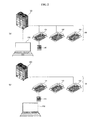
- a connected position of the control unit 150 may be changed.
- control unit 150 may be connected to the outdoor unit 120. If connected to the outdoor unit 120, the control unit 150 may receive data stored at the outdoor unit to determine a state of the air conditioner. In this case, all data may be received through the outdoor unit.
- control unit 150 may be connected to a communication line connected among the plurality of indoor units 131 to 133, 130, and, depending on cases, may be connected to the indoor unit.
- the control unit 150 having the communication line of the indoor units connected thereto may receive, not only the data stored at a particular unit, but also the data transmitted/received among the units through the communication line. For an example, since the control unit 150 may receive and display the data transmitted/received between the indoor unit 130 and the central controller 110, the control unit 150 may also receive and display a control flow by the central controller 110.
- the data the control unit 150 receives and displays may be vary depending on modes of connection of the control unit 150, i.e., depending on connection of the control unit 150 to the outdoor unit or the communication line of the indoor unit.
- the air conditioner system may include a plurality of control units 150 and 160.
- the first control unit 150 is connected to the air conditioner for collecting the data
- the second control unit 161 and 162, 160 makes mutual communication with the first control unit 150 for receiving information on the air conditioner.
- a plurality of the control units 150 and 160 may transmit/receive information in a variety of communication systems, and may display the data information in languages different from one another.
- the first control unit 150 may store and accumulate the data received as the first control unit 150 accesses to a separate data server 50, or may request the data if necessary.
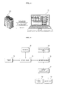
- FIG. 4 is schematic view illustrating data flows between a control unit in accordance with a preferred embodiment of the present invention and a unit of an air conditioner.
- control unit 150 may be connected to the outdoor unit for requesting the data, and the outdoor unit may transmit the information data on the air conditioner to the control unit 150 as requested.
- control unit 150 may be connected to the communication line of the indoor unit, and may receive the control signal between the indoor unit and the central controller to collect information on the air conditioner.
- the indoor unit 120 or the outdoor unit 130 may transmit the data information to the control unit 150, the data transmission is not limited to this, and the data information may be transmitted to the indoor unit 120 or the outdoor unit 130 at particular periods.
- FIG. 5 is a block diagram illustrating a control unit in accordance with a preferred embodiment of the present invention.
- control unit 150 includes a processor 10 for processing various signals and carrying out calculation, a memory 20 for storing programs and data in association with the processor 10, and an interface unit 30 for connecting peripheral units related to input or output to/from the processor 10.
- control unit 150 also includes a timer 70, a communication unit 80, and an input/output unit 40, an output unit 50, and an input unit 60.
- the processor 10 may carry out different functions for the control unit 150, and may run or carry out different software programs and/or sets of command languages stored in the memory 20 for processing the data.
- the processor 10 may process the signal based on information stored in the memory 20.
- the processor 10 may display the data stored in the memory 20 on the output unit 50, or may carry out the program stored in the memory 20.
- the processor 10 may carry out the program by calculating a time in association to the timer 70.
- the memory 20 may include at least one magnetic disk storage unit, a flash memory unit, or other non-volatile memory, such as a non-volatile solid memory unit, but not limited to this, and may include readable storage medium.
- the memory 20 may include, but not limited to, EEP-ROM (Electronically Erasable and Programmable Read Only Memory).
- EEP-ROM Electrically Erasable and Programmable Read Only Memory
- the EEP-ROM may have information written or erased by the processor 10 during operation of the processor 10.
- the EEP-ROM may be a memory device which maintains information memorized therein without being erased even if power to the control unit 150 is turned off to cut off power supply.
- the memory 20 stores different programs and data stored therein in association with the processor 10.
- the programs the memory 20 has stored therein are run by the processor.
- the processor 10 makes the communication unit 80 to receive the data information which is the operation information of the domestic appliance and to display the data received/transmitted thus.
- the data being displayed on a screen may be displayed in time series images or characters.
- the processor 10 may receive the data information from the outdoor unit selected thus, and may include an interface which one of the indoor units which will receive the information may select among one or more than one of the outdoor units connected to the outdoor unit selected thus.
- the information may include the operation state of the indoor units selected thus and connection states of the outdoor unit selected thus and the indoor unit selected thus.
- the processor 10 may receive information, and may display the operation states of the outdoor unit selected thus and the indoor unit selected thus, and the connection states thereof. And, the processor 10 may receive information on the outdoor unit or the indoor unit in real time, and may display the information in images or characters in real time through the output unit 50.
- the processor 10 display the data received thus in a set language.
- this processor 10 may display in a language other than a language stored therein.
- the processor 10 sets a data storage time period or storage period of the outdoor unit or the indoor unit and transmits the same to the outdoor unit and the indoor unit.
- the indoor unit and the outdoor unit store the data according to setting, and erase the data in an order a length of a storage time if the time period is passed.
- the processor 10 displays data in a real time or changes of the data in an order of times in succession if the data are ones produced before a fixed time.
- the processor may display elements of the indoor unit or the outdoor unit, for an example, the valve, pressure and temperature of the pipeline, and states of the heat exchanger and the compressor in images or moving images, and depending on cases, the operation state in different colors.
- a fan operation state of the indoor unit may be displayed in a rotating image of rotation blades, and a rotation speed of the fan may be displayed in a numerical value or a color.
- the flow may be displayed divided into a blue color and a red color depending on a temperature thereof, and valve on/off may be displayed in a valve form and a color change through the output unit 50.
- the processor 10 may display the data re-producing the data according to the time, while controlling a display speed thereof. That is, in displaying changes of the information with time, the display speed is controlled according to pass of time.
- the interface unit 30 connects the input and output peripheral units to the processor 10 and the memory 20.
- the processor 10, the memory 20, or the interface unit 30 may be embodied on single chip, but not limited to this, and may be embodied on individual chips.
- the timer 70 checks time.
- the processor 10 may determine whether a predetermined time is passed or not by using the timer 70 for carrying out a control.
- the timer 70 may calculate a re-producing rate of the images, but not limited to this, and there may be different embodiments.
- the input/output unit 40 connects the peripheral units, such as the output unit 50 and the input unit 60, to the interface unit 30 for relaying and controlling input/output of the data.
- the input/output unit 40 may include an input/output controller (Not shown) for controlling the output unit 50 or the input unit 60.
- the output unit 50 may include a speaker which emits sound, or a display unit which emits a light to make a visual display.
- the input unit 60 may include means which can receive an external input, such as a physical button, a dial, a slider switch, a click wheel, and so on.
- the output unit 50 may include at least one of LPD (Light Emitting Polymer Display), LCD (Liquid Crystal Display), TFT-LCD (Thin Film Transistor-Liquid Crystal Display), OLED (Organic Light-emitting Diode), flexible display), and 3D display, but not limited to those, and may include a variety of systems.
- LPD Light Emitting Polymer Display
- LCD Liquid Crystal Display
- TFT-LCD Thin Film Transistor-Liquid Crystal Display
- OLED Organic Light-emitting Diode
- the output unit 50 may display information for controlling an object the control unit 150 is connected thereto. If the control unit 150 is applied to the air conditioner system, the output unit 50 may display information required for air conditioning.
- the output unit 50 may display operation modes of the air conditioner, such as room cooling, room heating, dehumidifying, or air cleaning of the air conditioner, and may display a room temperature, a wind direction, and presence of a heat source in the room.
- operation modes of the air conditioner such as room cooling, room heating, dehumidifying, or air cleaning of the air conditioner, and may display a room temperature, a wind direction, and presence of a heat source in the room.
- the output unit 50 may be a touch sensing touch screen.
- the output unit 50 may be fabricated as one unit with the input unit.
- the touch sensing touch screen may display a visual output to a user, and may receive input from the user by sensing a touch.
- the visual output may include graphics, a text, an icon, a video, and a combination of above. If the output unit 50 includes the touch sensing touch screen, buttons on the input unit 60 described below may be replaced with user interfaces displayed on the touch screen.
- the input unit 60 may include at least one button, or a switch, and depending on cases, may include a touch pad which perceives an input with a pressure or static electricity.
- the input unit 60 and the output unit 50 may be controlled by the input/output controller (Not shown) in the input/output unit 40.
- the input unit 60 and the output unit 50 may include a plurality of interfaces matched to instruction words for carrying out the programs stored in the memory 20, or functions described before.
- the communication unit 80 is connected to the indoor unit 130, the outdoor unit 120, and the interface unit 30 for receiving a control signal from the interface unit 30 and transmitting the control signal to the indoor unit 130 or the outdoor unit 120, and receiving the operation states from the indoor unit 130 or the outdoor unit 120.
- the communication unit 80 may include an RF (Radio Frequency) circuit.
- the communication unit 80 may transmit/receive the RF signal which is an electro-magnetic signal.
- the RF circuit converts an electric signal and the electro-magnetic signal to the other, and may communicate with a communication network and other communication units with the electro-magnetic signal.
- the RF circuit may include an antenna system, an RF transceiver, at least one amplifier, a tuner, at least one oscillator, a digital signal processor, a CODEC chip set, and a memory, but not limited to those, and may include known circuits for carrying out the functions.
- the communication unit may use one of wireless communication systems selected from, but not limited to, Bluetooth, Radio Frequency Identification, IrDA (Infrared Data Association), Ultra Wideband, ZigBee, and Wi-Fi.
- the communication unit 80 may receive a signal from the processor 10 through the interface unit 30. If the communication unit 80 receives a control signal from the interface unit 30, the communication unit 80 may modulate the control signal and may transmit the signal modulated thus to the indoor unit 130 or the outdoor unit 120.
- FIG. 6 is an exemplary view illustrating a frame for monitoring an air conditioner displayed on a control unit in accordance with a preferred embodiment of the present invention.
- the control unit 150 receives information on equipped apparatuses including the outdoor unit and the indoor unit and forwards the information through the output unit 50.
- the output unit 50 displays information on a plurality of the equipped apparatuses connected thereto including the outdoor unit and the indoor unit.
- the output unit 50 may display the information on the equipped apparatuses on the frame dividing the frame into a monitoring window 220 and an information display window 210.
- the monitoring window 220 has an additional menu tap 228 for displaying a cycle view tap T120, and a detailed graph tap T130, and, if respective taps are selected, the cycle view window and the detailed graph window are displayed on the frame together with additional menus.
- the monitoring window 220 has a plurality of function buttons displayed thereon.
- the function buttons may be a storage button 229, a still shot button 230, a control button 231, and a help button 232.
- a plurality of data displayed by the present output unit 50 may be stored, together with time information.
- the still shot button 230 stores data displayed on the monitoring window 220 and the information display window 210 presently the same as an appearance of the frame in a still shot image.
- a storage period of the data monitored thus, and a storage time period of the data in one time of storage may be set.
- selection of the button is not required additionally, but the data is stored, periodically.
- change of the language displayed on the monitoring window 220 and the information display window 210 is possible, frame setting may be corrected, and a size of the image stored when the still shot is selected may be set.
- control button 231 when the control button 231 is selected, control setting for the equipped apparatuses is possible.
- the monitoring window 220 may have individual information and group information on an apparatus of the plurality of equipped apparatuses displayed thereon, and information on a particular apparatus selected at the monitoring window 220 is displayed on the information display window 210.
- the monitoring window 220 has the equipped apparatuses sorted, and information on the equipped apparatuses sorted in a plurality of the taps, such that, if one of the taps is selected, information on the equipped apparatus is displayed on the frame.
- the monitoring window 220 is divided into a plurality of regions for displaying data at the regions different from one another.
- the monitoring window displays basic operation information, group and individual apparatus information of the equipped apparatuses, the cycle information, measured data values, and an operation graph window 239 of each apparatuses.
- a control target value on a pressure or a temperature of the present equipped apparatus, for an example, the air conditioner, and data being measured presently are displayed.
- a group selection tap 237 is provided for enabling to select a group intended to display, and information on individual apparatus in the group is displayed in a list.
- the additional information tap 236 may display information on a special indoor unit on an additional window, additionally.
- the target pressure, the present pressure, a compression ratio, a room temperature, operation of each element, whether the valve of the outdoor unit 120 is in operation or not may be displayed, and a pressure of the outdoor unit 120 or the indoor unit 130, a temperature of the outdoor unit 120 or the indoor unit 130, a discharge pressure of the compressor, an EEV opening, and a fan speed are displayed.
- the pressure of the compressor, an operation frequency, a compressor temperature, a temperature of the outdoor unit, operation of an outdoor unit valve are selected with respective selection taps 238, for displaying a graph on each of items on the apparatus selected thus.
- the operation graph window 239 may display a plurality of pieces of information divided into colors different from one another, or thicknesses or line forms different from one another.
- the information displayed on the operation graph window 239 may also be displayed when the detailed graph tap T130 is selected, but may be displayed in more detail.
- the information display window 210 if one of the apparatuses displayed in the group information is selected, an operation mode, whether an error takes place or not, a kind of the error, and product information on a product type or version of the apparatus are displayed, together with information on a position of the apparatus selected thus. And, in the information display window 210, a communication state with the apparatus selected thus may also be displayed.
- FIG. 7 is an exemplary view illustrating a frame for monitoring an air conditioner cycle displayed on a control unit in accordance with a preferred embodiment of the present invention.
- the processor 10 displays information on a cycle of the air conditioner on a screen of the output unit 50 in an image.
- the cycle information is displayed on a cycle view frame 240 displayed on the output unit 50.
- the cycle view frame 240 has the apparatuses of the air conditioner arranged matched to actual connection states and installed positions thereon, for displaying the present operation states thereon.
- each of the apparatuses is displayed in an image, an icon, or a symbol which represents the apparatus and the operation state of each of the apparatuses is displayed in a color, a moving image, a character, or a numeral.
- the cycle view frame 240 displays cycle data changed in real time matched to the data on the operation state of the apparatus of the air conditioner.
- an outdoor unit fan or an indoor unit fan is displayed in an image of a rotating fan, and, if the fan image does not move (Does not rotate), it may be determined that the fan is in a turned off state. And, the operation state of the compressor may be displayed in a color, for an example, in red and green.
- the cycle view screen has an outdoor unit selection button T140 and an indoor unit selection button T150 for, if a particular outdoor unit is selected from the plurality of outdoor units of the air conditioner, displaying information on the outdoor unit selected thus, as well as the cycle view of apparatuses connected to the outdoor unit selected thus.
- the cycle view frame has an outdoor unit region V110 and an indoor unit region v120 displayed thereon divided the cycle view frame.
- information on a distributor connected to the indoor units is displayed altogether, and, in relation to this, a pipeline connection state V130 between the distributor and the indoor units is also displayed.
- the cycle information on the one or the group of the indoor units selected thus is displayed, together with information on the outdoor unit the one or the group of the indoor units selected thus is connected thereto.
- control unit 150 since the control unit 150 is connected not to single outdoor unit, and single indoor unit, the control unit 150 displays cycle information on apparatuses or groups selected from the plurality of equipped apparatuses.
- an operation information window 241 displays the operation information, product information, and information on installed site of the compressor.
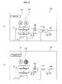
- FIGS. 8A and 8B are exemplary views each illustrating a cycle view frame displayed on a control unit in accordance with a preferred embodiment of the present invention.
- the cycle view frame 240 displays information on the operation state of one apparatus. Particularly, if something wrong, such as an error or a trouble, takes place, the cycle view frame 240 displays wrong states of respective apparatuses. And, the control unit 150 may issue an alarm, or a warning message, additionally.
- outdoor unit fans in the outdoor unit are displayed on the cycle view frame 240, and the outdoor unit fans 291 and 293 are displayed changed on the cycle view frame 240 matched to the operation states of actual outdoor unit fans.
- the outdoor unit fans are displayed on the cycle view frame matched to a number of the outdoor unit fans, too.
- the outdoor unit fans 291, and 292 on the cycle view frame matched to the actual outdoor unit fans are also displayed in rotating images, rotating in a higher or lower speed according to a change of the rotating speed, respectively.
- the first outdoor unit fan 291 which is in a normal rotation state is displayed in a rotating image normally, and the second outdoor unit fan 292 having something wrong taken place thereto has the warning displayed thereon.
- the warning may be displayed by displaying a color of the second outdoor unit fan 292 different from a color of the first outdoor unit fan 291.
- a popup window may be produced to output the warning message thereon, or an additional alarm may be issued by the control unit.
- the first outdoor unit fan 291 in a normal state may be displayed in green, and the second outdoor unit fan 292 having something wrong taken place thereto may be displayed in red.
- the second outdoor unit fan 292 may be displayed in an image which is not rotating, but stopped.
- the outdoor unit not only the outdoor unit, but also the compressor, the sensor, and the valve may be displayed with a changed color or an additional alarm may be issued, if something wrong takes place thereto.
- FIGS. 9A and 9B are exemplary views each illustrating inspection of an air conditioner by using a cycle view on a control unit in accordance with a preferred embodiment of the present invention.
- the control unit 150 displays a warning on the error on the cycle view frame 240.
- the warning may be a change of an image, a symbol, a form or color of an icon matched to the apparatus, a data on a wrong state is displayed, and, depending on cases, a warning message may be displayed. And, an alarm may also be issued.
- a user of the control unit 150 may determine the apparatus having something wrong taken place thereto with the cycle view frame.
- the apparatus displayed on the cycle view frame is displayed matched to an installed position thereof, and, if the apparatus having something wrong taken place thereto is selected, information on the installed position is displayed on the cycle view frame.
- an actual position 293 of the outdoor unit fan matched to the second outdoor unit fan is determined and the second outdoor unit fan may be inspected or repaired.
- FIGS. 10A and 10B are exemplary views each illustrating a cycle view frame on a control unit in accordance with a preferred embodiment of the present invention, displaying an error.
- operation information 295 is displayed on the cycle view frame displayed on the control unit.
- control unit displays information on the apparatus different from a normal state.
- a product type and version information on the product are also displayed, and information on an installed position may also be displayed. From FIG. 10A described before, the user may determine the installed position of the actual apparatus with the operation information window.
- help information 297 matched to the error code is displayed.
- the help information 297 displays description of the error code, a reason why the error code takes place, a position where the error takes place, and methods for inspecting and treating the error taken place thus, and an image to help understanding on taking place and treating of the error may be displayed, altogether.
- FIGS. 11 and 12 are exemplary views each illustrating information display on a cycle view frame on a control unit in accordance with a preferred embodiment of the present invention.
- the cycle view frame displays warning on an apparatus having something wrong taken place thereto
- the operation information is displayed at one region of the frame, and, as shown, a sub-menu 298 is displayed.
- the diagnosis menu runs a trouble diagnosis on operation of the apparatus having something wrong.
- the apparatus upon running the diagnosis menu, the apparatus is subjected to diagnosis in compliance with a predetermined diagnose logic based on data on the apparatus having something wrong, and a result of the diagnosis is displayed on the frame.
- the result of the diagnosis is stored to accumulate the results, and may be transmitted to an external terminal or other control unit when requested.
- a manual data on the apparatus having something wrong is displayed on the screen. And, as described before, the error information on the apparatus having something wrong may be displayed.
- operation data of a predetermined time period on the apparatus having something wrong is displayed in a graph based on data on the apparatus having something wrong.
- the apparatus is the outdoor unit fan
- variations on a rotation speed, whether operated or not, and an input voltage of the outdoor unit fan for a predetermined time period are displayed in the graph.
- the apparatus is the compressor
- variations on an operation frequency, a suction pressure, a discharge pressure, a suction temperature, and a discharge temperature for a predetermined time period are displayed in the graph.
- the sub-menu may not be displayed according to characteristic of the apparatus selected thus additionally, but the data on the apparatus selected thus may be displayed in the graph.
- the graph may be displayed on a new window, or at a region of the cycle view frame.
- a graph window 302 on the compressor is displayed on the frame.
- the graph shows changes based on the data for a predetermined time period, and the time period being shown may be changed according to a setting.
- control unit of the present invention can display the operation state of the air conditioner and information thereof on the cycle view frame easily, for the user to determine information on each of the apparatuses, easily.
Landscapes
- Engineering & Computer Science (AREA)
- Mechanical Engineering (AREA)
- General Engineering & Computer Science (AREA)
- Chemical & Material Sciences (AREA)
- Combustion & Propulsion (AREA)
- Human Computer Interaction (AREA)
- Physics & Mathematics (AREA)
- Thermal Sciences (AREA)
- Health & Medical Sciences (AREA)
- Biomedical Technology (AREA)
- Air Conditioning Control Device (AREA)
- Selective Calling Equipment (AREA)
Applications Claiming Priority (1)
| Application Number | Priority Date | Filing Date | Title |
|---|---|---|---|
| KR1020120127472A KR101517084B1 (ko) | 2012-11-12 | 2012-11-12 | 공기조화기용 제어장치 |
Publications (2)
| Publication Number | Publication Date |
|---|---|
| EP2733432A2 true EP2733432A2 (de) | 2014-05-21 |
| EP2733432A3 EP2733432A3 (de) | 2018-04-11 |
Family
ID=49578137
Family Applications (1)
| Application Number | Title | Priority Date | Filing Date |
|---|---|---|---|
| EP13192330.2A Withdrawn EP2733432A3 (de) | 2012-11-12 | 2013-11-11 | Vorrichtung zur Steuerung einer Klimaanlage |
Country Status (4)
| Country | Link |
|---|---|
| US (1) | US9964347B2 (de) |
| EP (1) | EP2733432A3 (de) |
| KR (1) | KR101517084B1 (de) |
| CN (1) | CN103807974B (de) |
Cited By (3)
| Publication number | Priority date | Publication date | Assignee | Title |
|---|---|---|---|---|
| EP2977688A1 (de) * | 2014-07-25 | 2016-01-27 | LG Electronics Inc. | Klimaanlagensystem |
| CN105465947A (zh) * | 2015-11-24 | 2016-04-06 | 珠海格力电器股份有限公司 | 空调故障处理方法、装置和系统 |
| CN111023441A (zh) * | 2019-12-30 | 2020-04-17 | Tcl空调器(中山)有限公司 | 一种空调控制方法、系统、存储介质及空调器 |
Families Citing this family (11)
| Publication number | Priority date | Publication date | Assignee | Title |
|---|---|---|---|---|
| KR101972039B1 (ko) * | 2012-11-12 | 2019-04-24 | 엘지전자 주식회사 | 공기조화기 시스템 |
| CN106170663B (zh) * | 2014-01-27 | 2020-04-07 | 日立江森自控空调有限公司 | 显示装置以及应用程序 |
| KR20160041561A (ko) | 2014-10-08 | 2016-04-18 | 엘지전자 주식회사 | 공기조화장치용 컨트롤러 |
| KR20160043402A (ko) | 2014-10-13 | 2016-04-21 | 엘지전자 주식회사 | 칠러용 컨트롤러 및 칠러의 제어방법 |
| DE102015103729A1 (de) * | 2015-03-13 | 2016-09-15 | Bitzer Kühlmaschinenbau Gmbh | Steuereinheit |
| KR101644452B1 (ko) * | 2015-11-04 | 2016-08-10 | 콘티넨탈 오토모티브 일렉트로닉스 유한회사 | 차량의 공조 상태 표시 장치 |
| JP6749131B2 (ja) * | 2016-04-11 | 2020-09-02 | 三菱電機株式会社 | 制御装置、サーバ、騒音監視システム、ヒートポンプ機器およびプログラム |
| KR102300791B1 (ko) | 2017-03-20 | 2021-09-09 | 엘지전자 주식회사 | 공기조화기 및 그 제어방법 |
| ES3031873T3 (en) * | 2020-02-05 | 2025-07-11 | Daikin Ind Ltd | Indicator |
| KR102852473B1 (ko) * | 2025-02-27 | 2025-08-29 | 주식회사 더인츠 | 시니어에 최적화된 스크린파크골프 유지관리시스템 |
| CN119879362B (zh) * | 2025-03-27 | 2025-05-27 | 视昀科技(深圳)有限公司 | 基于组态模型的冷源调度方法、设备及存储介质 |
Family Cites Families (50)
| Publication number | Priority date | Publication date | Assignee | Title |
|---|---|---|---|---|
| US5602758A (en) * | 1993-01-22 | 1997-02-11 | Gas Research Institute | Installation link-up procedure |
| JP3185086B2 (ja) * | 1995-02-03 | 2001-07-09 | 株式会社山武 | 空調監視装置 |
| US6122603A (en) * | 1998-05-29 | 2000-09-19 | Powerweb, Inc. | Multi-utility energy control system with dashboard |
| US20020011923A1 (en) | 2000-01-13 | 2002-01-31 | Thalia Products, Inc. | Appliance Communication And Control System And Appliance For Use In Same |
| US6647317B2 (en) | 2000-09-06 | 2003-11-11 | Hitachi Ltd | Air conditioner management system |
| US7774177B2 (en) * | 2001-06-29 | 2010-08-10 | Honda Motor Co., Ltd. | Exoskeleton controller for a human-exoskeleton system |
| US6978627B2 (en) * | 2002-01-31 | 2005-12-27 | Mitsubishi Denki Kabushiki Kaisha | Air conditioner control system, central remote controller, and facility controller |
| US6853882B2 (en) * | 2002-05-17 | 2005-02-08 | Carrier Corporation | HVAC system monitoring |
| US6983889B2 (en) * | 2003-03-21 | 2006-01-10 | Home Comfort Zones, Inc. | Forced-air zone climate control system for existing residential houses |
| JP3788980B2 (ja) * | 2003-04-14 | 2006-06-21 | 東芝キヤリア株式会社 | 空気調和機のリモートコントロール装置 |
| US7177776B2 (en) * | 2003-05-27 | 2007-02-13 | Siemens Building Technologies, Inc. | System and method for developing and processing building system control solutions |
| KR100565486B1 (ko) | 2003-06-11 | 2006-03-30 | 엘지전자 주식회사 | 에어컨의 중앙제어 시스템 및 그 동작방법 |
| US7055759B2 (en) * | 2003-08-18 | 2006-06-06 | Honeywell International Inc. | PDA configuration of thermostats |
| US6955302B2 (en) * | 2003-11-13 | 2005-10-18 | York International Corporation | Remote monitoring diagnostics |
| KR100626443B1 (ko) | 2003-11-24 | 2006-09-20 | 엘지전자 주식회사 | 공기조화기의 실내기 |
| BRPI0418649A (pt) | 2004-04-20 | 2007-05-29 | Lg Electronics Inc | ar condicionado |
| KR100631540B1 (ko) * | 2004-10-26 | 2006-10-09 | 엘지전자 주식회사 | 히트 펌프식 멀티형 공기조화기의 가스관 막힘 검출시스템및 방법 |
| KR100640851B1 (ko) | 2004-12-09 | 2006-11-02 | 엘지전자 주식회사 | 멀티 에어컨 시스템의 상태 모니터링 장치 및 그 방법 |
| KR101120325B1 (ko) * | 2005-08-18 | 2012-03-08 | 엘지전자 주식회사 | 아바타 냉장고 |
| US7539587B2 (en) * | 2005-09-22 | 2009-05-26 | University Of Tennessee Research Foundation | Rate-based sensors for advanced real-time analysis and diagnostics |
| KR100680218B1 (ko) | 2005-12-31 | 2007-02-08 | 엘지전자 주식회사 | 빌딩관리시스템 및 그의 통신방법 |
| KR100789012B1 (ko) * | 2006-05-08 | 2007-12-26 | 대우조선해양 주식회사 | 소부재 용접로봇 자가진단시스템 |
| KR101048545B1 (ko) | 2006-12-04 | 2011-07-12 | 현대중공업 주식회사 | 원격상태 감시기반 엔진운전 및 유지보수 관리 시스템 |
| KR20080059909A (ko) | 2006-12-26 | 2008-07-01 | 엘지전자 주식회사 | 멀티형 공기조화기 |
| JP4992452B2 (ja) * | 2007-02-13 | 2012-08-08 | ダイキン工業株式会社 | 空気調和装置のリモートコントロールユニット |
| US20090027334A1 (en) | 2007-06-01 | 2009-01-29 | Cybernet Systems Corporation | Method for controlling a graphical user interface for touchscreen-enabled computer systems |
| US8239922B2 (en) | 2007-08-27 | 2012-08-07 | Honeywell International Inc. | Remote HVAC control with user privilege setup |
| KR101321542B1 (ko) | 2007-10-02 | 2013-10-25 | 엘지전자 주식회사 | 공기조화장치용 제어장치 |
| KR20090041604A (ko) | 2007-10-24 | 2009-04-29 | 엘지전자 주식회사 | 공기조화기 |
| KR101450540B1 (ko) | 2007-10-30 | 2014-10-15 | 엘지전자 주식회사 | 공기조화기의 에러관리 시스템 |
| JP4396779B2 (ja) * | 2008-01-24 | 2010-01-13 | ダイキン工業株式会社 | 空調機管理装置 |
| JP5001876B2 (ja) * | 2008-02-25 | 2012-08-15 | 三菱重工業株式会社 | 空調システムおよび空調制御監視装置 |
| CN201209936Y (zh) * | 2008-04-02 | 2009-03-18 | 上海兆丰多媒体生活广场发展有限公司 | 一种用于中央空调系统和机电设备的监视屏 |
| AU2009250756B2 (en) | 2008-05-22 | 2012-11-08 | Daikin Industries, Ltd. | Equipment management apparatus |
| US8433446B2 (en) * | 2008-10-27 | 2013-04-30 | Lennox Industries, Inc. | Alarm and diagnostics system and method for a distributed-architecture heating, ventilation and air conditioning network |
| EP2427862B1 (de) | 2009-05-08 | 2016-07-27 | Accenture Global Services Limited | System zur analyse des energieverbrauchs eines gebäudes |
| KR20100123487A (ko) * | 2009-05-15 | 2010-11-24 | 엘지전자 주식회사 | 공기조화기 시스템 및 그 동작방법 |
| US8855830B2 (en) * | 2009-08-21 | 2014-10-07 | Allure Energy, Inc. | Energy management system and method |
| US9838255B2 (en) * | 2009-08-21 | 2017-12-05 | Samsung Electronics Co., Ltd. | Mobile demand response energy management system with proximity control |
| KR20110043254A (ko) * | 2009-10-21 | 2011-04-27 | 엘지전자 주식회사 | 원격 관리 시스템 및 원격 관리 서버 |
| US8260444B2 (en) | 2010-02-17 | 2012-09-04 | Lennox Industries Inc. | Auxiliary controller of a HVAC system |
| WO2011133578A1 (en) * | 2010-04-20 | 2011-10-27 | Equal Networks Incorporated | Apparatus, system, and method having a wi-fi compatible alternating current (ac) power circuit module |
| US10346275B2 (en) * | 2010-11-19 | 2019-07-09 | Google Llc | Attributing causation for energy usage and setpoint changes with a network-connected thermostat |
| US20120251963A1 (en) * | 2011-03-31 | 2012-10-04 | Siemens Industry, Inc. | Thermostat with integrated carbon monoxide (co) sensor |
| CN103748620A (zh) * | 2011-04-22 | 2014-04-23 | 艾克潘尔基公司 | 用于分析能量使用的系统和方法 |
| KR101111731B1 (ko) * | 2011-05-19 | 2012-03-13 | 주식회사 한국안테나 | 그래픽 유저 인터페이스를 이용한 led조명의 스마트 제어시스템 |
| KR101161203B1 (ko) * | 2011-09-20 | 2012-07-02 | 하이에어공조 주식회사 | 공기조화기 리모콘 |
| KR101256324B1 (ko) * | 2011-11-30 | 2013-04-18 | 엘지전자 주식회사 | 공기 조화기의 설치가이드 시스템의 이용방법 |
| KR101972039B1 (ko) * | 2012-11-12 | 2019-04-24 | 엘지전자 주식회사 | 공기조화기 시스템 |
| KR101482139B1 (ko) * | 2012-11-12 | 2015-01-14 | 엘지전자 주식회사 | 공기조화기용 제어장치 및 그 동작방법 |
-
2012
- 2012-11-12 KR KR1020120127472A patent/KR101517084B1/ko not_active Expired - Fee Related
-
2013
- 2013-11-11 EP EP13192330.2A patent/EP2733432A3/de not_active Withdrawn
- 2013-11-12 US US14/077,417 patent/US9964347B2/en active Active
- 2013-11-12 CN CN201310560030.3A patent/CN103807974B/zh not_active Expired - Fee Related
Non-Patent Citations (1)
| Title |
|---|
| None |
Cited By (3)
| Publication number | Priority date | Publication date | Assignee | Title |
|---|---|---|---|---|
| EP2977688A1 (de) * | 2014-07-25 | 2016-01-27 | LG Electronics Inc. | Klimaanlagensystem |
| CN105465947A (zh) * | 2015-11-24 | 2016-04-06 | 珠海格力电器股份有限公司 | 空调故障处理方法、装置和系统 |
| CN111023441A (zh) * | 2019-12-30 | 2020-04-17 | Tcl空调器(中山)有限公司 | 一种空调控制方法、系统、存储介质及空调器 |
Also Published As
| Publication number | Publication date |
|---|---|
| EP2733432A3 (de) | 2018-04-11 |
| CN103807974B (zh) | 2016-11-02 |
| KR20140061581A (ko) | 2014-05-22 |
| US9964347B2 (en) | 2018-05-08 |
| US20140137583A1 (en) | 2014-05-22 |
| CN103807974A (zh) | 2014-05-21 |
| KR101517084B1 (ko) | 2015-05-04 |
Similar Documents
| Publication | Publication Date | Title |
|---|---|---|
| US9964347B2 (en) | Apparatus for controlling an air conditioner | |
| US9400129B2 (en) | Apparatus for controlling an air conditioner and a method for operating the same | |
| EP2733431A2 (de) | Klimaanlagensystem | |
| US8826165B2 (en) | System status user interfaces | |
| KR102122266B1 (ko) | 가전기기, 가전기기 시스템 및 그 제어방법 | |
| EP3009901B1 (de) | Steuerung für einen kühler und verfahren zur steuerung eines kühlers | |
| US20160025369A1 (en) | Air conditioning system | |
| KR101972038B1 (ko) | 제어장치 및 그를 포함하는 공기조화기 시스템 | |
| US20050284161A1 (en) | Air conditioning system and method for controlling the same | |
| KR101963615B1 (ko) | 제어장치 및 그를 포함하는 공기조화기 시스템 | |
| KR102381558B1 (ko) | 공기조화기의 제어장치 | |
| KR101972040B1 (ko) | 공기조화기용 제어장치 및 그 동작방법 | |
| KR20130022295A (ko) | 공기조화기 제어장치 및 이의 운전방법 | |
| EP3007018B1 (de) | Steuerung für eine klimaanlagenvorrichtung | |
| EP3232132B1 (de) | Klimatisierungssystem | |
| KR102010389B1 (ko) | 제어장치 | |
| US20210285676A1 (en) | Air-conditioning system | |
| KR102143347B1 (ko) | 원격제어기 및 그를 포함하는 공기조화기 시스템 | |
| KR20140132187A (ko) | 제어장치 | |
| JP2001182995A (ja) | 冷凍空調機の運転状況の表示方法及びその装置 | |
| KR20180092018A (ko) | 공기조화기 제어장치 및 그의 동작방법 | |
| KR20150039023A (ko) | 공기조화기 및 공기조화기 제어방법 |
Legal Events
| Date | Code | Title | Description |
|---|---|---|---|
| PUAI | Public reference made under article 153(3) epc to a published international application that has entered the european phase |
Free format text: ORIGINAL CODE: 0009012 |
|
| 17P | Request for examination filed |
Effective date: 20131204 |
|
| AK | Designated contracting states |
Kind code of ref document: A2 Designated state(s): AL AT BE BG CH CY CZ DE DK EE ES FI FR GB GR HR HU IE IS IT LI LT LU LV MC MK MT NL NO PL PT RO RS SE SI SK SM TR |
|
| AX | Request for extension of the european patent |
Extension state: BA ME |
|
| PUAL | Search report despatched |
Free format text: ORIGINAL CODE: 0009013 |
|
| AK | Designated contracting states |
Kind code of ref document: A3 Designated state(s): AL AT BE BG CH CY CZ DE DK EE ES FI FR GB GR HR HU IE IS IT LI LT LU LV MC MK MT NL NO PL PT RO RS SE SI SK SM TR |
|
| AX | Request for extension of the european patent |
Extension state: BA ME |
|
| RIC1 | Information provided on ipc code assigned before grant |
Ipc: F24F 11/02 20060101AFI20180306BHEP Ipc: F25B 49/00 20060101ALI20180306BHEP |
|
| STAA | Information on the status of an ep patent application or granted ep patent |
Free format text: STATUS: REQUEST FOR EXAMINATION WAS MADE |
|
| RIC1 | Information provided on ipc code assigned before grant |
Ipc: F25B 49/00 20060101ALI20180306BHEP Ipc: F24F 11/02 20060101AFI20180306BHEP |
|
| STAA | Information on the status of an ep patent application or granted ep patent |
Free format text: STATUS: THE APPLICATION IS DEEMED TO BE WITHDRAWN |
|
| 18D | Application deemed to be withdrawn |
Effective date: 20181012 |