EP2732146B1 - Verfahren und vorrichtung zum betreiben einer brennkraftmaschine - Google Patents
Verfahren und vorrichtung zum betreiben einer brennkraftmaschine Download PDFInfo
- Publication number
- EP2732146B1 EP2732146B1 EP20120720899 EP12720899A EP2732146B1 EP 2732146 B1 EP2732146 B1 EP 2732146B1 EP 20120720899 EP20120720899 EP 20120720899 EP 12720899 A EP12720899 A EP 12720899A EP 2732146 B1 EP2732146 B1 EP 2732146B1
- Authority
- EP
- European Patent Office
- Prior art keywords
- cylinder
- torque
- diagnostic mode
- measured
- cylinders
- Prior art date
- Legal status (The legal status is an assumption and is not a legal conclusion. Google has not performed a legal analysis and makes no representation as to the accuracy of the status listed.)
- Not-in-force
Links
Images
Classifications
-
- F—MECHANICAL ENGINEERING; LIGHTING; HEATING; WEAPONS; BLASTING
- F02—COMBUSTION ENGINES; HOT-GAS OR COMBUSTION-PRODUCT ENGINE PLANTS
- F02D—CONTROLLING COMBUSTION ENGINES
- F02D41/00—Electrical control of supply of combustible mixture or its constituents
- F02D41/02—Circuit arrangements for generating control signals
- F02D41/14—Introducing closed-loop corrections
- F02D41/1497—With detection of the mechanical response of the engine
-
- F—MECHANICAL ENGINEERING; LIGHTING; HEATING; WEAPONS; BLASTING
- F02—COMBUSTION ENGINES; HOT-GAS OR COMBUSTION-PRODUCT ENGINE PLANTS
- F02D—CONTROLLING COMBUSTION ENGINES
- F02D41/00—Electrical control of supply of combustible mixture or its constituents
- F02D41/02—Circuit arrangements for generating control signals
- F02D41/14—Introducing closed-loop corrections
-
- B—PERFORMING OPERATIONS; TRANSPORTING
- B60—VEHICLES IN GENERAL
- B60W—CONJOINT CONTROL OF VEHICLE SUB-UNITS OF DIFFERENT TYPE OR DIFFERENT FUNCTION; CONTROL SYSTEMS SPECIALLY ADAPTED FOR HYBRID VEHICLES; ROAD VEHICLE DRIVE CONTROL SYSTEMS FOR PURPOSES NOT RELATED TO THE CONTROL OF A PARTICULAR SUB-UNIT
- B60W10/00—Conjoint control of vehicle sub-units of different type or different function
- B60W10/04—Conjoint control of vehicle sub-units of different type or different function including control of propulsion units
- B60W10/06—Conjoint control of vehicle sub-units of different type or different function including control of propulsion units including control of combustion engines
-
- B—PERFORMING OPERATIONS; TRANSPORTING
- B60—VEHICLES IN GENERAL
- B60W—CONJOINT CONTROL OF VEHICLE SUB-UNITS OF DIFFERENT TYPE OR DIFFERENT FUNCTION; CONTROL SYSTEMS SPECIALLY ADAPTED FOR HYBRID VEHICLES; ROAD VEHICLE DRIVE CONTROL SYSTEMS FOR PURPOSES NOT RELATED TO THE CONTROL OF A PARTICULAR SUB-UNIT
- B60W10/00—Conjoint control of vehicle sub-units of different type or different function
- B60W10/04—Conjoint control of vehicle sub-units of different type or different function including control of propulsion units
- B60W10/08—Conjoint control of vehicle sub-units of different type or different function including control of propulsion units including control of electric propulsion units, e.g. motors or generators
-
- B—PERFORMING OPERATIONS; TRANSPORTING
- B60—VEHICLES IN GENERAL
- B60W—CONJOINT CONTROL OF VEHICLE SUB-UNITS OF DIFFERENT TYPE OR DIFFERENT FUNCTION; CONTROL SYSTEMS SPECIALLY ADAPTED FOR HYBRID VEHICLES; ROAD VEHICLE DRIVE CONTROL SYSTEMS FOR PURPOSES NOT RELATED TO THE CONTROL OF A PARTICULAR SUB-UNIT
- B60W20/00—Control systems specially adapted for hybrid vehicles
- B60W20/50—Control strategies for responding to system failures, e.g. for fault diagnosis, failsafe operation or limp mode
-
- F—MECHANICAL ENGINEERING; LIGHTING; HEATING; WEAPONS; BLASTING
- F02—COMBUSTION ENGINES; HOT-GAS OR COMBUSTION-PRODUCT ENGINE PLANTS
- F02D—CONTROLLING COMBUSTION ENGINES
- F02D41/00—Electrical control of supply of combustible mixture or its constituents
- F02D41/008—Controlling each cylinder individually
- F02D41/0087—Selective cylinder activation, i.e. partial cylinder operation
-
- F—MECHANICAL ENGINEERING; LIGHTING; HEATING; WEAPONS; BLASTING
- F02—COMBUSTION ENGINES; HOT-GAS OR COMBUSTION-PRODUCT ENGINE PLANTS
- F02D—CONTROLLING COMBUSTION ENGINES
- F02D41/00—Electrical control of supply of combustible mixture or its constituents
- F02D41/22—Safety or indicating devices for abnormal conditions
-
- B—PERFORMING OPERATIONS; TRANSPORTING
- B60—VEHICLES IN GENERAL
- B60K—ARRANGEMENT OR MOUNTING OF PROPULSION UNITS OR OF TRANSMISSIONS IN VEHICLES; ARRANGEMENT OR MOUNTING OF PLURAL DIVERSE PRIME-MOVERS IN VEHICLES; AUXILIARY DRIVES FOR VEHICLES; INSTRUMENTATION OR DASHBOARDS FOR VEHICLES; ARRANGEMENTS IN CONNECTION WITH COOLING, AIR INTAKE, GAS EXHAUST OR FUEL SUPPLY OF PROPULSION UNITS IN VEHICLES
- B60K6/00—Arrangement or mounting of plural diverse prime-movers for mutual or common propulsion, e.g. hybrid propulsion systems comprising electric motors and internal combustion engines
- B60K6/20—Arrangement or mounting of plural diverse prime-movers for mutual or common propulsion, e.g. hybrid propulsion systems comprising electric motors and internal combustion engines the prime-movers consisting of electric motors and internal combustion engines, e.g. HEVs
- B60K6/42—Arrangement or mounting of plural diverse prime-movers for mutual or common propulsion, e.g. hybrid propulsion systems comprising electric motors and internal combustion engines the prime-movers consisting of electric motors and internal combustion engines, e.g. HEVs characterised by the architecture of the hybrid electric vehicle
- B60K6/48—Parallel type
- B60K2006/4825—Electric machine connected or connectable to gearbox input shaft
-
- B—PERFORMING OPERATIONS; TRANSPORTING
- B60—VEHICLES IN GENERAL
- B60W—CONJOINT CONTROL OF VEHICLE SUB-UNITS OF DIFFERENT TYPE OR DIFFERENT FUNCTION; CONTROL SYSTEMS SPECIALLY ADAPTED FOR HYBRID VEHICLES; ROAD VEHICLE DRIVE CONTROL SYSTEMS FOR PURPOSES NOT RELATED TO THE CONTROL OF A PARTICULAR SUB-UNIT
- B60W50/00—Details of control systems for road vehicle drive control not related to the control of a particular sub-unit, e.g. process diagnostic or vehicle driver interfaces
- B60W50/02—Ensuring safety in case of control system failures, e.g. by diagnosing, circumventing or fixing failures
- B60W50/0205—Diagnosing or detecting failures; Failure detection models
- B60W2050/021—Means for detecting failure or malfunction
-
- B—PERFORMING OPERATIONS; TRANSPORTING
- B60—VEHICLES IN GENERAL
- B60W—CONJOINT CONTROL OF VEHICLE SUB-UNITS OF DIFFERENT TYPE OR DIFFERENT FUNCTION; CONTROL SYSTEMS SPECIALLY ADAPTED FOR HYBRID VEHICLES; ROAD VEHICLE DRIVE CONTROL SYSTEMS FOR PURPOSES NOT RELATED TO THE CONTROL OF A PARTICULAR SUB-UNIT
- B60W2510/00—Input parameters relating to a particular sub-units
- B60W2510/24—Energy storage means
- B60W2510/242—Energy storage means for electrical energy
- B60W2510/244—Charge state
-
- F—MECHANICAL ENGINEERING; LIGHTING; HEATING; WEAPONS; BLASTING
- F02—COMBUSTION ENGINES; HOT-GAS OR COMBUSTION-PRODUCT ENGINE PLANTS
- F02D—CONTROLLING COMBUSTION ENGINES
- F02D2200/00—Input parameters for engine control
- F02D2200/02—Input parameters for engine control the parameters being related to the engine
- F02D2200/10—Parameters related to the engine output, e.g. engine torque or engine speed
- F02D2200/1002—Output torque
- F02D2200/1004—Estimation of the output torque
-
- F—MECHANICAL ENGINEERING; LIGHTING; HEATING; WEAPONS; BLASTING
- F02—COMBUSTION ENGINES; HOT-GAS OR COMBUSTION-PRODUCT ENGINE PLANTS
- F02D—CONTROLLING COMBUSTION ENGINES
- F02D2250/00—Engine control related to specific problems or objectives
- F02D2250/18—Control of the engine output torque
- F02D2250/24—Control of the engine output torque by using an external load, e.g. a generator
-
- F—MECHANICAL ENGINEERING; LIGHTING; HEATING; WEAPONS; BLASTING
- F02—COMBUSTION ENGINES; HOT-GAS OR COMBUSTION-PRODUCT ENGINE PLANTS
- F02D—CONTROLLING COMBUSTION ENGINES
- F02D41/00—Electrical control of supply of combustible mixture or its constituents
- F02D41/24—Electrical control of supply of combustible mixture or its constituents characterised by the use of digital means
- F02D41/2406—Electrical control of supply of combustible mixture or its constituents characterised by the use of digital means using essentially read only memories
- F02D41/2425—Particular ways of programming the data
- F02D41/2429—Methods of calibrating or learning
- F02D41/2451—Methods of calibrating or learning characterised by what is learned or calibrated
- F02D41/2464—Characteristics of actuators
- F02D41/2467—Characteristics of actuators for injectors
- F02D41/247—Behaviour for small quantities
-
- F—MECHANICAL ENGINEERING; LIGHTING; HEATING; WEAPONS; BLASTING
- F02—COMBUSTION ENGINES; HOT-GAS OR COMBUSTION-PRODUCT ENGINE PLANTS
- F02P—IGNITION, OTHER THAN COMPRESSION IGNITION, FOR INTERNAL-COMBUSTION ENGINES; TESTING OF IGNITION TIMING IN COMPRESSION-IGNITION ENGINES
- F02P19/00—Incandescent ignition, e.g. during starting of internal combustion engines; Combination of incandescent and spark ignition
- F02P19/02—Incandescent ignition, e.g. during starting of internal combustion engines; Combination of incandescent and spark ignition electric, e.g. layout of circuits of apparatus having glowing plugs
- F02P19/027—Safety devices, e.g. for diagnosing the glow plugs or the related circuits
-
- Y—GENERAL TAGGING OF NEW TECHNOLOGICAL DEVELOPMENTS; GENERAL TAGGING OF CROSS-SECTIONAL TECHNOLOGIES SPANNING OVER SEVERAL SECTIONS OF THE IPC; TECHNICAL SUBJECTS COVERED BY FORMER USPC CROSS-REFERENCE ART COLLECTIONS [XRACs] AND DIGESTS
- Y02—TECHNOLOGIES OR APPLICATIONS FOR MITIGATION OR ADAPTATION AGAINST CLIMATE CHANGE
- Y02T—CLIMATE CHANGE MITIGATION TECHNOLOGIES RELATED TO TRANSPORTATION
- Y02T10/00—Road transport of goods or passengers
- Y02T10/60—Other road transportation technologies with climate change mitigation effect
- Y02T10/62—Hybrid vehicles
Definitions
- the invention relates to a method for operating a drive device which, for providing a drive torque, comprises a plurality of internal combustion engines each having a torque contribution in a normal operation, and at least one electric machine operatively connected thereto.
- the invention relates to a computer program product with a program code stored on a machine-readable carrier for carrying out the above-mentioned method.
- EP 114 3134 discloses a method in which the torque is simulated by the electric machine.
- the method according to the invention is characterized in that a cylinder-selective measurement of at least one characteristic operating variable takes place in a diagnostic mode, for which only the cylinder to be measured is operated in the diagnostic mode and the torque contributions of the remaining cylinders are simulated by the electric machine.
- the inventive method has the advantage that the drive torque is maintained in total, so that a driver of the drive device having a difference feels while simultaneously operated only the cylinder to be measured and thus its characteristic operating size is detected independently of the other cylinders and no distortion of the Measurement result is carried out by other cylinders of the internal combustion engine. Characterized in that the torque contributions of the other cylinders are simulated by the electric machine, the drive device behaves in the diagnostic mode with respect to the drive torque as well as in the normal operating mode.
- the drive torque of the drive device can also be increased or reduced during the diagnostic mode.
- This makes it possible, in particular by providing only a single sensor, which is provided in the common exhaust tract of the cylinder, to carry out the cylinder-specific measurement of the characteristic operating variable.
- the diagnostic mode is set as a function of a torque which can currently be produced by the electric machine or performed. This ensures that the electric machine can always emulate the torque contributions of the other cylinders at least for a minimum period of time. If the electric machine is not able to reproduce the torque contributions of the remaining cylinders, the diagnostic mode is disabled, otherwise a sudden torque drop of the drive device would result.
- the diagnostic mode is preferably set or performed as a function of a current state of charge of an energy store assigned to the electric machine. It is provided in particular that, when the current state of charge of the energy storage device falls below a predefinable threshold, the diagnostic mode is disabled.
- the diagnostic mode takes place until the characteristic operating variable of the cylinder to be measured has been detected.
- the torque contributions of the remaining cylinders are thus simulated by the electric machine until the characteristic operating variable of the cylinder to be measured has been reliably and clearly detected.
- this period of time is limited as a function of the current state of charge of the electric machine, as described above, so that an overstressing of the energy store is avoided.
- the diagnostic mode is carried out until the exhaust gas mixture of the remaining cylinders has been discharged and thus only the exhaust gas of the cylinder to be measured is available.
- the characteristic operating variable is measured successively in all cylinders.
- a cylinder is always operated, while the torque contributions of the remaining cylinders are simulated by the electric machine.
- another of the cylinders provides its torque contribution, while the others, including the previously torque-supplying cylinder, are deactivated and simulated by the electric machine.
- the characteristic operating variable for each of the cylinders is clearly measured or determined.
- a suspect cylinder here is to be understood as meaning a cylinder of the internal combustion engine which is suspected of failing to meet a setpoint value with regard to the operating variable or not to perform it with sufficient accuracy.
- the suspect cylinder can be detected, for example on the basis of a cylinder-selective measurement according to a method of the prior art and then confirmed by the inventive method or measured in detail or with a higher accuracy.
- intake and / or exhaust valves of the remaining cylinders are closed in the diagnostic mode in order to measure the cylinder-specific gas exchange of the operated cylinder.
- the drive device or the internal combustion engine is equipped with a corresponding valve drive, which allows an individual actuation of its valves. If the inlet and outlet valves of the other cylinders are closed, air is only delivered through the cylinder to be measured, so that the cylinder-specific influence of the air is measured.
- the electric machine while the cylinder to be measured makes its contribution to torque, the electric machine generates a supporting or counteracting torque.
- a higher or lower load of the cylinder to be measured may be advantageous.
- the electric machine acts to assist or counteract, while the cylinder provides a lower or higher torque contribution relative to the actual desired contribution.
- the cylinder to be measured provides an increased torque in the diagnostic mode or is filled or supplied with an increased fuel quantity, whereby the characteristic operating variable can be detected more easily or more clearly.
- the electric machine acts - as already mentioned - preferably counter to compensate for the additional torque.
- the device according to the invention is distinguished by a specially prepared control device which contains means for carrying out the method as described above.
- the control unit is preferably associated with at least one sensor for detecting the characteristic operating variable and interfaces that allow the control unit to control the internal combustion engine and the electric machine as described above, to allow the cylinder-specific measurement of the operating variable.
- the computer program product according to the invention is characterized by a program code for carrying out the method described above when the program is executed on a computer.
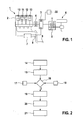
- FIG. 1 shows a drive device 1 for a motor vehicle, which includes an internal combustion engine 2 and an electric machine 3.
- the internal combustion engine 2 is operatively connected via an actuatable clutch 4 with the electric machine 3.
- the electric machine 3 is the output side further connected to a transmission 5, which may be formed as an automatic transmission or manual transmission.
- the transmission 5 is connected on the output side to a drive axle 6, which is only indicated here, of the motor vehicle (not shown).
- the drive device 1 further comprises a device 7 which is connected at least to the internal combustion engine 2 and the electric machine 3 in order to control them.
- the device 7 is connected to a sensor 8, which is arranged in an exhaust tract 9 of the internal combustion engine 2, to detect at least a certain size of the exhaust gas, such as the oxygen content of the exhaust gas.
- the internal combustion engine 2 has a plurality of cylinders 10, 11, 12 and 13, whose exhaust ports open into the common exhaust tract 9, so that all exhaust gases of the cylinders 10-13 are guided past the sensor 8.
- a first step 14 the drive device 1 is put into operation and preferably set a normal operation.
- normal operation here is an operation to understand in which all cylinders 10-13 of the engine 2 make a contribution to torque, which acts on the drive shaft 6 with the clutch 4 closed.
- a diagnostic mode is activated in which a cylinder-selective measurement of at least one characteristic operating variable takes place by means of the sensor 8.
- a fuel-air ratio is measured by means of the designed as a lambda probe sensor 8 cylinder-selectively.
- a known from the prior art method is preferably used, in which, depending on the angle of rotation of the crankshaft of the internal combustion engine 1, which is detected by means of a crankshaft sensor, determines the time at which the exhaust gas of a particular cylinder of the cylinders 10 to 12 the Sensor 8 happens. If it is found that one of the cylinders delivers an implausible or unexpected value of the recorded operating variable, the diagnostic method is advantageously continued as follows:
- the current state of charge of an electrical energy store 22 assigned to the electric machine 3, which was previously detected in a step 17, is compared with a threshold value which was predetermined beforehand, for example during application of the drive device. If the current state of charge is below the threshold value, the diagnostic program is either aborted or suspended until the state of charge reaches a value that is above the threshold value. This can be achieved for example by an operation of the drive device in one generator mode can be achieved when the electric machine 3 is driven by the internal combustion engine 2.
- the operating range of the internal combustion engine 2 is checked in a step 18 and decided whether the electric machine 3 can emulate the missing torque contributions of the remaining cylinders 11-13, ie whether the power of the electric motor 3 is sufficient in the current operating range of the drive device 1, to provide a correspondingly high torque.
- the process continues (j) to a further step 19 in which the internal combustion engine 2 is controlled in such a way that the cylinder suspected previously in step 15, for example 10, supplies its torque contribution is controlled while the remaining cylinder 11 to 13 deactivated, that is no longer used or fired.
- the electric machine 3 is controlled in such a way that it simulates the torque contributions of the remaining cylinders 11-13. In other words, the electric machine 3 simulates the missing torque contributions of the cylinders 11, 12 and 13, so that the same drive torque continues to be applied to the drive axle 6 and, in particular, the driver does not notice a difference in driving behavior, except perhaps from an acoustic difference.
- the sensor 8 detects only the exhaust gas leaving the cylinder 10, whereby the influence of the cylinder 10 on the characteristic operating variable to be measured is detected very accurately.
- the diagnostic mode is maintained until the characteristic operating variable of the cylinder 10 has been clearly detected, but at least until the exhaust gas mixture of the remaining cylinders 11 to 13 has left the exhaust tract 9 or was discharged.
- the exhaust gas temperature, the exhaust gas pressure or the torque contribution of the cylinder 10 to be measured can also be measured or be recorded.
- cylinder-specific corrections in particular with regard to the injection quantity and / or the injection time of fuel, the ignition timing or the opening times and / or strokes of the intake and / or exhaust valves of the respective cylinder can be performed.
- only corresponding sensors or means must be provided which enable the detection of the respective value.
- the speed of the internal combustion engine and preferably the crankshaft angle is detected, and taken into account in the control of the electric machine 3 in order to accurately replicate the missing torque contributions can.
- the engine speed signal is fed directly to a control unit of the electric machine 3.
- the diagnostic program or the diagnostic mode is ended in a concluding step 21.
- the cylinder-selective measurement is performed for one cylinder after the other, so that always operates a cylinder and the torque contributions of the remaining cylinders are readjusted by the electric machine 3, wherein only the cylinder to be measured is supplied with fuel and optionally ignited.
- step 15 is omitted, wherein all cylinders of the internal combustion engine 2 or the values of all cylinders 10-13 are measured in succession according to steps 19 and 20.
- the advantageous method makes it possible to determine, for example, whether the inlet and / or outlet valves open or close as intended, whether the heating power of glow plugs is sufficient, in particular during warm-up, and / or if the injection quantity of the injector is within predetermined tolerance limits.
- the at least one sensor 8, in particular in the described embodiment as a lambda sensor, is arranged in the exhaust tract 9 in the immediate vicinity of the merging or mixing point of the cylinder-specific exhaust gases in order to minimize transit time and mixing effects.
- the timing of the measurement is important and is preferably done by crankshaft angle or intake and exhaust valve positions synchronously or synchronously, for example every millisecond. If the measured values of different sensors in a different installation location in the exhaust gas tract 9 are compared or offset, the transit times in the exhaust gas tract can be taken into account or also determined by modeling.
- the cylinder to be measured can be supplied with an excess amount of an injection quantity and the unwanted excess amount of the torque for the total drive power can be compensated by the electric machine 3.
- not all cylinders are preferably operated by internal combustion engines, so that only selected cylinders Contribute torque contribution, and the remaining cylinder (at least one) simulated by the electric machine 3 or replaced.
- the advantageous method is preferably used in the workshop diagnosis, where, for example, by integrating external exhaust gas analyzers and other measuring devices that include, for example, acoustic sensors, the cylinder-specific diagnostic options are further improved.
- the electric machine 3 preferably tows the internal combustion engine 2 to a diagnostic operating point, so that a cylinder-specific diagnosis is advantageously also made possible during the start and / or warm-up phase.
- the influence of the driver and the driving cycle of the real driving operation is here preferably hidden. Desired operating conditions for the cylinder-specific diagnosis of the internal combustion engine 2, which are cumbersome to reach in normal driving, can be displayed here in a simpler way.
- the invention is not limited to a drive device whose internal combustion engine and electric machine as in FIG. 1 represented connected to each other.
- internal combustion engine 2 and electric machine 3 for example, also be connected in parallel. It is also conceivable to connect the internal combustion engine 2 to a drive axle, and the electric motor 3 to another drive axle of the same motor vehicle.
Landscapes
- Engineering & Computer Science (AREA)
- Chemical & Material Sciences (AREA)
- Combustion & Propulsion (AREA)
- Mechanical Engineering (AREA)
- General Engineering & Computer Science (AREA)
- Transportation (AREA)
- Biomedical Technology (AREA)
- General Health & Medical Sciences (AREA)
- Automation & Control Theory (AREA)
- Health & Medical Sciences (AREA)
- Combined Controls Of Internal Combustion Engines (AREA)
- Output Control And Ontrol Of Special Type Engine (AREA)
- Hybrid Electric Vehicles (AREA)
- Electric Propulsion And Braking For Vehicles (AREA)
- Testing Of Engines (AREA)
Applications Claiming Priority (2)
| Application Number | Priority Date | Filing Date | Title |
|---|---|---|---|
| DE102011078930A DE102011078930A1 (de) | 2011-07-11 | 2011-07-11 | Verfahren und Vorrichtung zum Betreiben einer Antriebsvorrichtung sowie Computer-Programm-Produkt |
| PCT/EP2012/059101 WO2013007428A1 (de) | 2011-07-11 | 2012-05-16 | Verfahren und vorrichtung zum betreiben einer brennkraftmaschine |
Publications (2)
| Publication Number | Publication Date |
|---|---|
| EP2732146A1 EP2732146A1 (de) | 2014-05-21 |
| EP2732146B1 true EP2732146B1 (de) | 2015-04-29 |
Family
ID=46085063
Family Applications (1)
| Application Number | Title | Priority Date | Filing Date |
|---|---|---|---|
| EP20120720899 Not-in-force EP2732146B1 (de) | 2011-07-11 | 2012-05-16 | Verfahren und vorrichtung zum betreiben einer brennkraftmaschine |
Country Status (7)
| Country | Link |
|---|---|
| US (1) | US9376976B2 (enExample) |
| EP (1) | EP2732146B1 (enExample) |
| JP (1) | JP5809748B2 (enExample) |
| KR (1) | KR101898882B1 (enExample) |
| CN (1) | CN103649504B (enExample) |
| DE (1) | DE102011078930A1 (enExample) |
| WO (1) | WO2013007428A1 (enExample) |
Families Citing this family (15)
| Publication number | Priority date | Publication date | Assignee | Title |
|---|---|---|---|---|
| SE540690C2 (sv) * | 2013-11-21 | 2018-10-09 | Scania Cv Ab | Förfarande och system för adaption av åtminstone en injektorvid en förbränningsmotor |
| JP5949819B2 (ja) * | 2014-03-25 | 2016-07-13 | トヨタ自動車株式会社 | 内燃機関の燃料噴射制御装置 |
| JP6135580B2 (ja) * | 2014-03-31 | 2017-05-31 | マツダ株式会社 | エンジンの制御装置 |
| FR3052724B1 (fr) * | 2016-06-17 | 2018-07-13 | Continental Automotive France | Procede de detection d'irregularites de combustion d'une unite de type moteur a combustion interne couplee a une unite de propulsion electrique, d'un vehicule automobile hybride |
| US11636870B2 (en) | 2020-08-20 | 2023-04-25 | Denso International America, Inc. | Smoking cessation systems and methods |
| US11760170B2 (en) | 2020-08-20 | 2023-09-19 | Denso International America, Inc. | Olfaction sensor preservation systems and methods |
| US12251991B2 (en) | 2020-08-20 | 2025-03-18 | Denso International America, Inc. | Humidity control for olfaction sensors |
| US11932080B2 (en) | 2020-08-20 | 2024-03-19 | Denso International America, Inc. | Diagnostic and recirculation control systems and methods |
| US12377711B2 (en) | 2020-08-20 | 2025-08-05 | Denso International America, Inc. | Vehicle feature control systems and methods based on smoking |
| US11881093B2 (en) | 2020-08-20 | 2024-01-23 | Denso International America, Inc. | Systems and methods for identifying smoking in vehicles |
| US11828210B2 (en) | 2020-08-20 | 2023-11-28 | Denso International America, Inc. | Diagnostic systems and methods of vehicles using olfaction |
| US11813926B2 (en) | 2020-08-20 | 2023-11-14 | Denso International America, Inc. | Binding agent and olfaction sensor |
| US12017506B2 (en) | 2020-08-20 | 2024-06-25 | Denso International America, Inc. | Passenger cabin air control systems and methods |
| US12269315B2 (en) | 2020-08-20 | 2025-04-08 | Denso International America, Inc. | Systems and methods for measuring and managing odor brought into rental vehicles |
| US11760169B2 (en) | 2020-08-20 | 2023-09-19 | Denso International America, Inc. | Particulate control systems and methods for olfaction sensors |
Family Cites Families (20)
| Publication number | Priority date | Publication date | Assignee | Title |
|---|---|---|---|---|
| US4448063A (en) * | 1983-02-03 | 1984-05-15 | Ingersoll-Rand Company | Engine cold testing |
| US5355713A (en) * | 1991-02-05 | 1994-10-18 | Lucas Hartridge, Inc. | Cold engine testing |
| US5417109A (en) * | 1993-09-30 | 1995-05-23 | Lucas Automation & Control Engineering, Inc. | Methods and apparatus for testing engines |
| JP3575255B2 (ja) | 1997-12-15 | 2004-10-13 | 日産自動車株式会社 | ハイブリッド車の作動気筒数制御装置 |
| EP1143134B1 (en) | 1998-12-24 | 2012-08-08 | Toyota Jidosha Kabushiki Kaisha | Output state detector for internal combustion engine |
| DE10006161A1 (de) | 2000-02-11 | 2001-08-23 | Bosch Gmbh Robert | Verfahren und Einrichtung zur Bestimmung zylinderindividueller Unterschiede einer Steuergröße bei einer mehrzylindrigen Brennkraftmaschine |
| US6889133B2 (en) * | 2000-02-17 | 2005-05-03 | General Electric Company | System and process for detection of weak or non-functioning cylinders in engines |
| US6691807B1 (en) | 2000-04-11 | 2004-02-17 | Ford Global Technologies Llc | Hybrid electric vehicle with variable displacement engine |
| DE10025846B8 (de) * | 2000-05-25 | 2007-09-20 | Conti Temic Microelectronic Gmbh | Verfahren zur zylinderselektiven Dichtigkeitsprüfung der Brennräume einer Brennkraftmaschine |
| US6708557B2 (en) * | 2002-02-13 | 2004-03-23 | Wisconsin Alumni Research Foundation | Internal combustion engine simulation and testing |
| JP4179815B2 (ja) * | 2002-06-25 | 2008-11-12 | マツダ株式会社 | テスト対象エンジンの圧縮上死点検出装置 |
| JP2006009664A (ja) | 2004-06-24 | 2006-01-12 | Toyota Motor Corp | 動力出力装置およびこれを搭載する自動車並びに動力出力装置の制御方法 |
| JP2007126073A (ja) | 2005-11-07 | 2007-05-24 | Nissan Motor Co Ltd | エンジンの振動抑制装置 |
| JP2007290663A (ja) | 2006-04-27 | 2007-11-08 | Toyota Motor Corp | 内燃機関の故障検出装置 |
| DE102006020349A1 (de) | 2006-04-28 | 2007-10-31 | Mahle International Gmbh | Kolbenmotor und zugehöriges Betriebsverfahren |
| JP2008120266A (ja) * | 2006-11-13 | 2008-05-29 | Toyota Motor Corp | ハイブリッド車両の燃料性状推定装置 |
| JP2010215183A (ja) * | 2009-03-18 | 2010-09-30 | Hitachi Automotive Systems Ltd | 車両制御装置 |
| JP5103459B2 (ja) * | 2009-10-30 | 2012-12-19 | 日立オートモティブシステムズ株式会社 | エンジンの制御装置 |
| DE102010012649A1 (de) * | 2010-01-18 | 2011-07-21 | ThyssenKrupp Krause GmbH, 28777 | Verfahren zur Ermittlung der Leistung eines Verbrennungsmotors |
| US9188505B2 (en) * | 2013-06-21 | 2015-11-17 | Ford Global Technologies, Llc | Method and system for cylinder compression diagnostics |
-
2011
- 2011-07-11 DE DE102011078930A patent/DE102011078930A1/de not_active Withdrawn
-
2012
- 2012-05-16 CN CN201280034290.0A patent/CN103649504B/zh not_active Expired - Fee Related
- 2012-05-16 JP JP2014519464A patent/JP5809748B2/ja not_active Expired - Fee Related
- 2012-05-16 KR KR1020147000683A patent/KR101898882B1/ko not_active Expired - Fee Related
- 2012-05-16 WO PCT/EP2012/059101 patent/WO2013007428A1/de not_active Ceased
- 2012-05-16 EP EP20120720899 patent/EP2732146B1/de not_active Not-in-force
- 2012-05-16 US US14/232,320 patent/US9376976B2/en not_active Expired - Fee Related
Also Published As
| Publication number | Publication date |
|---|---|
| DE102011078930A1 (de) | 2013-01-17 |
| CN103649504B (zh) | 2016-06-29 |
| KR101898882B1 (ko) | 2018-09-14 |
| US20140136078A1 (en) | 2014-05-15 |
| CN103649504A (zh) | 2014-03-19 |
| JP2014521542A (ja) | 2014-08-28 |
| US9376976B2 (en) | 2016-06-28 |
| KR20140043115A (ko) | 2014-04-08 |
| WO2013007428A1 (de) | 2013-01-17 |
| EP2732146A1 (de) | 2014-05-21 |
| JP5809748B2 (ja) | 2015-11-11 |
Similar Documents
| Publication | Publication Date | Title |
|---|---|---|
| EP2732146B1 (de) | Verfahren und vorrichtung zum betreiben einer brennkraftmaschine | |
| DE69701738T2 (de) | Kalibrierungsverfahren für ein elektronisches kraftstoffeinspritzsystem | |
| WO2009000647A2 (de) | Verfahren und vorrichtung zur diagnose eines mit einer kraftstoffverteilerleiste in verbindung stehenden einspritzventils einer brennkraftmaschine | |
| EP2021607A1 (de) | Verfahren und vorrichtung zur diagnose der wirksamkeit eines abgaskatalysators | |
| AT522353B1 (de) | Prüfstand und Verfahren zur Durchführung eines Prüflaufs auf einem Prüfstand | |
| DE60302636T2 (de) | Dieselmotor mit Vorrichtung zur Steuerung der Kraftstoffeinspritzmenge | |
| DE102009055120B4 (de) | Verfahren zum Überprüfen einer Funktion eines Aktuators bzw. eines Sensors, Verfahren zum Kalibrieren eines Aktuators bzw. eines Sensors sowie entsprechende Vorrichtung | |
| DE102004038733A1 (de) | Verfahren und Vorrichtung zum Betreiben einer Brennkraftmaschine | |
| DE102008043315A1 (de) | Verfahren zum Betreiben einer Brennkraftmaschine und Steuer- und/oder Regeleinrichtung für eine Brennkraftmaschine | |
| DE102011081634A1 (de) | Verfahren und Vorrichtung zur Diagnose eines Fehlers in einem Abgasrückführungssystem | |
| DE102011087961A1 (de) | Verfahren zum Lernen einer minimalen Ansteuerdauer von Einspritzventilen eines Verbrennungsmotors | |
| DE10006264C1 (de) | Brennkraftmaschine und Verfahren zum Betrieb einer Brennkraftmaschine | |
| WO2013113542A1 (de) | Verfahren zur steuerung einer brennkraftmaschine | |
| DE102012204332B4 (de) | Vorrichtung zum Betreiben einer Brennkraftmaschine | |
| DE10248627B4 (de) | Verfahren zum Betreiben einer Brennkraftmaschine, Brennkraftmaschine sowie Steuergerät hierfür | |
| WO2017097615A1 (de) | Verfahren zum betreiben einer brennkraftmaschine | |
| EP2640947A1 (de) | Verfahren und vorrichtung zur regelung eines ottomotors im selbstzündungsbetrieb | |
| DE102004015835B4 (de) | Vorrichtung zum Steuern einer Brennkraftmaschine | |
| DE10304242B3 (de) | Verfahren zur Ermittlung eines Parameters einer Verbrennung in einem Zylinder einer mehrzylindrigen Brennkraftmaschine, Brennkraftmaschine mit einer mehrflutiger Abgasanlage und mehrflutige Abgasanlage | |
| WO2016202481A1 (de) | Verfahren und vorrichtung zur ermittlung des beladungszustands eines abgaspartikelfilters | |
| DE102011086613A1 (de) | Verfahren zum Betrieb einer Brennkraftmaschine | |
| DE10230830A1 (de) | Verfahren und Vorrichtung zum Erkennen von Aussetzern und Rückführen unvollständig verbrannter Abgasgemische in Brennkraftmaschinen | |
| AT527010B1 (de) | Verfahren zur Bewertung der Brennstabilität einer Brennkraftmaschine | |
| DE10311519A1 (de) | Verfahren zum Betreiben einer Brennkraftmaschine | |
| DE10251364A1 (de) | Verfahren und Vorrichtung zur Bestimmung der Sekundärluftmasse bei einem Verbrennungsmotor |
Legal Events
| Date | Code | Title | Description |
|---|---|---|---|
| PUAI | Public reference made under article 153(3) epc to a published international application that has entered the european phase |
Free format text: ORIGINAL CODE: 0009012 |
|
| 17P | Request for examination filed |
Effective date: 20140211 |
|
| AK | Designated contracting states |
Kind code of ref document: A1 Designated state(s): AL AT BE BG CH CY CZ DE DK EE ES FI FR GB GR HR HU IE IS IT LI LT LU LV MC MK MT NL NO PL PT RO RS SE SI SK SM TR |
|
| DAX | Request for extension of the european patent (deleted) | ||
| GRAP | Despatch of communication of intention to grant a patent |
Free format text: ORIGINAL CODE: EPIDOSNIGR1 |
|
| RIC1 | Information provided on ipc code assigned before grant |
Ipc: F02D 41/00 20060101ALI20150109BHEP Ipc: F02D 41/22 20060101ALI20150109BHEP Ipc: F02D 41/14 20060101AFI20150109BHEP |
|
| INTG | Intention to grant announced |
Effective date: 20150205 |
|
| GRAS | Grant fee paid |
Free format text: ORIGINAL CODE: EPIDOSNIGR3 |
|
| GRAA | (expected) grant |
Free format text: ORIGINAL CODE: 0009210 |
|
| AK | Designated contracting states |
Kind code of ref document: B1 Designated state(s): AL AT BE BG CH CY CZ DE DK EE ES FI FR GB GR HR HU IE IS IT LI LT LU LV MC MK MT NL NO PL PT RO RS SE SI SK SM TR |
|
| REG | Reference to a national code |
Ref country code: GB Ref legal event code: FG4D Free format text: NOT ENGLISH |
|
| REG | Reference to a national code |
Ref country code: CH Ref legal event code: EP |
|
| REG | Reference to a national code |
Ref country code: AT Ref legal event code: REF Ref document number: 724582 Country of ref document: AT Kind code of ref document: T Effective date: 20150515 |
|
| REG | Reference to a national code |
Ref country code: IE Ref legal event code: FG4D Free format text: LANGUAGE OF EP DOCUMENT: GERMAN |
|
| REG | Reference to a national code |
Ref country code: DE Ref legal event code: R096 Ref document number: 502012003001 Country of ref document: DE Effective date: 20150611 |
|
| REG | Reference to a national code |
Ref country code: NL Ref legal event code: VDEP Effective date: 20150429 |
|
| REG | Reference to a national code |
Ref country code: LT Ref legal event code: MG4D |
|
| PG25 | Lapsed in a contracting state [announced via postgrant information from national office to epo] |
Ref country code: NL Free format text: LAPSE BECAUSE OF FAILURE TO SUBMIT A TRANSLATION OF THE DESCRIPTION OR TO PAY THE FEE WITHIN THE PRESCRIBED TIME-LIMIT Effective date: 20150429 |
|
| PG25 | Lapsed in a contracting state [announced via postgrant information from national office to epo] |
Ref country code: PT Free format text: LAPSE BECAUSE OF FAILURE TO SUBMIT A TRANSLATION OF THE DESCRIPTION OR TO PAY THE FEE WITHIN THE PRESCRIBED TIME-LIMIT Effective date: 20150831 Ref country code: LT Free format text: LAPSE BECAUSE OF FAILURE TO SUBMIT A TRANSLATION OF THE DESCRIPTION OR TO PAY THE FEE WITHIN THE PRESCRIBED TIME-LIMIT Effective date: 20150429 Ref country code: HR Free format text: LAPSE BECAUSE OF FAILURE TO SUBMIT A TRANSLATION OF THE DESCRIPTION OR TO PAY THE FEE WITHIN THE PRESCRIBED TIME-LIMIT Effective date: 20150429 Ref country code: NO Free format text: LAPSE BECAUSE OF FAILURE TO SUBMIT A TRANSLATION OF THE DESCRIPTION OR TO PAY THE FEE WITHIN THE PRESCRIBED TIME-LIMIT Effective date: 20150729 Ref country code: FI Free format text: LAPSE BECAUSE OF FAILURE TO SUBMIT A TRANSLATION OF THE DESCRIPTION OR TO PAY THE FEE WITHIN THE PRESCRIBED TIME-LIMIT Effective date: 20150429 Ref country code: ES Free format text: LAPSE BECAUSE OF FAILURE TO SUBMIT A TRANSLATION OF THE DESCRIPTION OR TO PAY THE FEE WITHIN THE PRESCRIBED TIME-LIMIT Effective date: 20150429 |
|
| PG25 | Lapsed in a contracting state [announced via postgrant information from national office to epo] |
Ref country code: IS Free format text: LAPSE BECAUSE OF FAILURE TO SUBMIT A TRANSLATION OF THE DESCRIPTION OR TO PAY THE FEE WITHIN THE PRESCRIBED TIME-LIMIT Effective date: 20150829 Ref country code: LV Free format text: LAPSE BECAUSE OF FAILURE TO SUBMIT A TRANSLATION OF THE DESCRIPTION OR TO PAY THE FEE WITHIN THE PRESCRIBED TIME-LIMIT Effective date: 20150429 Ref country code: GR Free format text: LAPSE BECAUSE OF FAILURE TO SUBMIT A TRANSLATION OF THE DESCRIPTION OR TO PAY THE FEE WITHIN THE PRESCRIBED TIME-LIMIT Effective date: 20150730 Ref country code: RS Free format text: LAPSE BECAUSE OF FAILURE TO SUBMIT A TRANSLATION OF THE DESCRIPTION OR TO PAY THE FEE WITHIN THE PRESCRIBED TIME-LIMIT Effective date: 20150429 |
|
| REG | Reference to a national code |
Ref country code: CH Ref legal event code: PL |
|
| PG25 | Lapsed in a contracting state [announced via postgrant information from national office to epo] |
Ref country code: CH Free format text: LAPSE BECAUSE OF NON-PAYMENT OF DUE FEES Effective date: 20150531 Ref country code: MC Free format text: LAPSE BECAUSE OF FAILURE TO SUBMIT A TRANSLATION OF THE DESCRIPTION OR TO PAY THE FEE WITHIN THE PRESCRIBED TIME-LIMIT Effective date: 20150429 Ref country code: DK Free format text: LAPSE BECAUSE OF FAILURE TO SUBMIT A TRANSLATION OF THE DESCRIPTION OR TO PAY THE FEE WITHIN THE PRESCRIBED TIME-LIMIT Effective date: 20150429 Ref country code: EE Free format text: LAPSE BECAUSE OF FAILURE TO SUBMIT A TRANSLATION OF THE DESCRIPTION OR TO PAY THE FEE WITHIN THE PRESCRIBED TIME-LIMIT Effective date: 20150429 Ref country code: LI Free format text: LAPSE BECAUSE OF NON-PAYMENT OF DUE FEES Effective date: 20150531 |
|
| REG | Reference to a national code |
Ref country code: DE Ref legal event code: R097 Ref document number: 502012003001 Country of ref document: DE |
|
| REG | Reference to a national code |
Ref country code: IE Ref legal event code: MM4A |
|
| PG25 | Lapsed in a contracting state [announced via postgrant information from national office to epo] |
Ref country code: PL Free format text: LAPSE BECAUSE OF FAILURE TO SUBMIT A TRANSLATION OF THE DESCRIPTION OR TO PAY THE FEE WITHIN THE PRESCRIBED TIME-LIMIT Effective date: 20150429 Ref country code: RO Free format text: LAPSE BECAUSE OF NON-PAYMENT OF DUE FEES Effective date: 20150429 Ref country code: SK Free format text: LAPSE BECAUSE OF FAILURE TO SUBMIT A TRANSLATION OF THE DESCRIPTION OR TO PAY THE FEE WITHIN THE PRESCRIBED TIME-LIMIT Effective date: 20150429 Ref country code: CZ Free format text: LAPSE BECAUSE OF FAILURE TO SUBMIT A TRANSLATION OF THE DESCRIPTION OR TO PAY THE FEE WITHIN THE PRESCRIBED TIME-LIMIT Effective date: 20150429 |
|
| PLBE | No opposition filed within time limit |
Free format text: ORIGINAL CODE: 0009261 |
|
| STAA | Information on the status of an ep patent application or granted ep patent |
Free format text: STATUS: NO OPPOSITION FILED WITHIN TIME LIMIT |
|
| 26N | No opposition filed |
Effective date: 20160201 |
|
| PG25 | Lapsed in a contracting state [announced via postgrant information from national office to epo] |
Ref country code: IE Free format text: LAPSE BECAUSE OF NON-PAYMENT OF DUE FEES Effective date: 20150516 |
|
| REG | Reference to a national code |
Ref country code: FR Ref legal event code: PLFP Year of fee payment: 5 |
|
| PG25 | Lapsed in a contracting state [announced via postgrant information from national office to epo] |
Ref country code: SI Free format text: LAPSE BECAUSE OF FAILURE TO SUBMIT A TRANSLATION OF THE DESCRIPTION OR TO PAY THE FEE WITHIN THE PRESCRIBED TIME-LIMIT Effective date: 20150429 |
|
| PG25 | Lapsed in a contracting state [announced via postgrant information from national office to epo] |
Ref country code: MT Free format text: LAPSE BECAUSE OF FAILURE TO SUBMIT A TRANSLATION OF THE DESCRIPTION OR TO PAY THE FEE WITHIN THE PRESCRIBED TIME-LIMIT Effective date: 20150429 |
|
| REG | Reference to a national code |
Ref country code: FR Ref legal event code: PLFP Year of fee payment: 6 |
|
| PG25 | Lapsed in a contracting state [announced via postgrant information from national office to epo] |
Ref country code: SM Free format text: LAPSE BECAUSE OF FAILURE TO SUBMIT A TRANSLATION OF THE DESCRIPTION OR TO PAY THE FEE WITHIN THE PRESCRIBED TIME-LIMIT Effective date: 20150429 Ref country code: HU Free format text: LAPSE BECAUSE OF FAILURE TO SUBMIT A TRANSLATION OF THE DESCRIPTION OR TO PAY THE FEE WITHIN THE PRESCRIBED TIME-LIMIT; INVALID AB INITIO Effective date: 20120516 Ref country code: BG Free format text: LAPSE BECAUSE OF FAILURE TO SUBMIT A TRANSLATION OF THE DESCRIPTION OR TO PAY THE FEE WITHIN THE PRESCRIBED TIME-LIMIT Effective date: 20150429 |
|
| PG25 | Lapsed in a contracting state [announced via postgrant information from national office to epo] |
Ref country code: SE Free format text: LAPSE BECAUSE OF FAILURE TO SUBMIT A TRANSLATION OF THE DESCRIPTION OR TO PAY THE FEE WITHIN THE PRESCRIBED TIME-LIMIT Effective date: 20150429 Ref country code: CY Free format text: LAPSE BECAUSE OF FAILURE TO SUBMIT A TRANSLATION OF THE DESCRIPTION OR TO PAY THE FEE WITHIN THE PRESCRIBED TIME-LIMIT Effective date: 20150429 |
|
| PG25 | Lapsed in a contracting state [announced via postgrant information from national office to epo] |
Ref country code: BE Free format text: LAPSE BECAUSE OF NON-PAYMENT OF DUE FEES Effective date: 20150531 |
|
| PG25 | Lapsed in a contracting state [announced via postgrant information from national office to epo] |
Ref country code: TR Free format text: LAPSE BECAUSE OF FAILURE TO SUBMIT A TRANSLATION OF THE DESCRIPTION OR TO PAY THE FEE WITHIN THE PRESCRIBED TIME-LIMIT Effective date: 20150429 |
|
| PG25 | Lapsed in a contracting state [announced via postgrant information from national office to epo] |
Ref country code: LU Free format text: LAPSE BECAUSE OF NON-PAYMENT OF DUE FEES Effective date: 20150516 |
|
| REG | Reference to a national code |
Ref country code: FR Ref legal event code: PLFP Year of fee payment: 7 |
|
| PG25 | Lapsed in a contracting state [announced via postgrant information from national office to epo] |
Ref country code: MK Free format text: LAPSE BECAUSE OF FAILURE TO SUBMIT A TRANSLATION OF THE DESCRIPTION OR TO PAY THE FEE WITHIN THE PRESCRIBED TIME-LIMIT Effective date: 20150429 |
|
| REG | Reference to a national code |
Ref country code: AT Ref legal event code: MM01 Ref document number: 724582 Country of ref document: AT Kind code of ref document: T Effective date: 20170516 |
|
| PG25 | Lapsed in a contracting state [announced via postgrant information from national office to epo] |
Ref country code: AT Free format text: LAPSE BECAUSE OF NON-PAYMENT OF DUE FEES Effective date: 20170516 |
|
| PG25 | Lapsed in a contracting state [announced via postgrant information from national office to epo] |
Ref country code: AL Free format text: LAPSE BECAUSE OF FAILURE TO SUBMIT A TRANSLATION OF THE DESCRIPTION OR TO PAY THE FEE WITHIN THE PRESCRIBED TIME-LIMIT Effective date: 20150429 |
|
| PGFP | Annual fee paid to national office [announced via postgrant information from national office to epo] |
Ref country code: FR Payment date: 20200519 Year of fee payment: 9 |
|
| PGFP | Annual fee paid to national office [announced via postgrant information from national office to epo] |
Ref country code: GB Payment date: 20200522 Year of fee payment: 9 Ref country code: IT Payment date: 20200528 Year of fee payment: 9 |
|
| GBPC | Gb: european patent ceased through non-payment of renewal fee |
Effective date: 20210516 |
|
| PG25 | Lapsed in a contracting state [announced via postgrant information from national office to epo] |
Ref country code: GB Free format text: LAPSE BECAUSE OF NON-PAYMENT OF DUE FEES Effective date: 20210516 |
|
| PG25 | Lapsed in a contracting state [announced via postgrant information from national office to epo] |
Ref country code: FR Free format text: LAPSE BECAUSE OF NON-PAYMENT OF DUE FEES Effective date: 20210531 |
|
| PG25 | Lapsed in a contracting state [announced via postgrant information from national office to epo] |
Ref country code: IT Free format text: LAPSE BECAUSE OF NON-PAYMENT OF DUE FEES Effective date: 20200516 |
|
| PGFP | Annual fee paid to national office [announced via postgrant information from national office to epo] |
Ref country code: DE Payment date: 20230726 Year of fee payment: 12 |
|
| REG | Reference to a national code |
Ref country code: DE Ref legal event code: R119 Ref document number: 502012003001 Country of ref document: DE |
|
| PG25 | Lapsed in a contracting state [announced via postgrant information from national office to epo] |
Ref country code: DE Free format text: LAPSE BECAUSE OF NON-PAYMENT OF DUE FEES Effective date: 20241203 |
|
| PG25 | Lapsed in a contracting state [announced via postgrant information from national office to epo] |
Ref country code: IT Free format text: LAPSE BECAUSE OF NON-PAYMENT OF DUE FEES Effective date: 20210516 |