EP2731508B1 - Dispositif écarteur chirurgical - Google Patents
Dispositif écarteur chirurgical Download PDFInfo
- Publication number
- EP2731508B1 EP2731508B1 EP12741176.7A EP12741176A EP2731508B1 EP 2731508 B1 EP2731508 B1 EP 2731508B1 EP 12741176 A EP12741176 A EP 12741176A EP 2731508 B1 EP2731508 B1 EP 2731508B1
- Authority
- EP
- European Patent Office
- Prior art keywords
- retractor
- frame
- membrane
- resilient frame
- deformable resilient
- Prior art date
- Legal status (The legal status is an assumption and is not a legal conclusion. Google has not performed a legal analysis and makes no representation as to the accuracy of the status listed.)
- Active
Links
- 239000012528 membrane Substances 0.000 claims description 98
- 230000008878 coupling Effects 0.000 claims description 30
- 238000010168 coupling process Methods 0.000 claims description 30
- 238000005859 coupling reaction Methods 0.000 claims description 30
- 238000003780 insertion Methods 0.000 claims description 10
- 230000037431 insertion Effects 0.000 claims description 10
- 238000007629 laparoscopic insertion Methods 0.000 claims description 2
- 210000004379 membrane Anatomy 0.000 description 96
- 238000001356 surgical procedure Methods 0.000 description 32
- 210000000056 organ Anatomy 0.000 description 28
- 238000000034 method Methods 0.000 description 26
- 208000027418 Wounds and injury Diseases 0.000 description 20
- 210000000683 abdominal cavity Anatomy 0.000 description 19
- 238000010586 diagram Methods 0.000 description 19
- 229920000642 polymer Polymers 0.000 description 18
- 239000000463 material Substances 0.000 description 17
- 210000003200 peritoneal cavity Anatomy 0.000 description 17
- 238000002357 laparoscopic surgery Methods 0.000 description 16
- 210000001015 abdomen Anatomy 0.000 description 15
- 210000003815 abdominal wall Anatomy 0.000 description 14
- 210000001835 viscera Anatomy 0.000 description 14
- 230000003187 abdominal effect Effects 0.000 description 13
- 229910052751 metal Inorganic materials 0.000 description 13
- 239000002184 metal Substances 0.000 description 13
- 230000000284 resting effect Effects 0.000 description 12
- 235000010627 Phaseolus vulgaris Nutrition 0.000 description 9
- 244000046052 Phaseolus vulgaris Species 0.000 description 9
- 230000006835 compression Effects 0.000 description 9
- 238000007906 compression Methods 0.000 description 9
- 230000008569 process Effects 0.000 description 8
- 238000002350 laparotomy Methods 0.000 description 7
- 238000007789 sealing Methods 0.000 description 7
- 238000012084 abdominal surgery Methods 0.000 description 6
- 230000006378 damage Effects 0.000 description 6
- -1 for example Substances 0.000 description 6
- 210000004197 pelvis Anatomy 0.000 description 6
- 208000014674 injury Diseases 0.000 description 5
- 230000007246 mechanism Effects 0.000 description 5
- 229920003023 plastic Polymers 0.000 description 5
- 238000002271 resection Methods 0.000 description 5
- 210000000574 retroperitoneal space Anatomy 0.000 description 5
- 230000008901 benefit Effects 0.000 description 4
- 230000003247 decreasing effect Effects 0.000 description 4
- 229920001971 elastomer Polymers 0.000 description 4
- 210000003903 pelvic floor Anatomy 0.000 description 4
- 239000004033 plastic Substances 0.000 description 4
- 230000008439 repair process Effects 0.000 description 4
- 210000001519 tissue Anatomy 0.000 description 4
- 239000000853 adhesive Substances 0.000 description 3
- 230000001070 adhesive effect Effects 0.000 description 3
- 238000012321 colectomy Methods 0.000 description 3
- 239000002131 composite material Substances 0.000 description 3
- 239000004744 fabric Substances 0.000 description 3
- 230000006870 function Effects 0.000 description 3
- 210000001035 gastrointestinal tract Anatomy 0.000 description 3
- 150000002739 metals Chemical class 0.000 description 3
- 229910001000 nickel titanium Inorganic materials 0.000 description 3
- 230000036961 partial effect Effects 0.000 description 3
- 239000004814 polyurethane Substances 0.000 description 3
- 229920002635 polyurethane Polymers 0.000 description 3
- 230000000452 restraining effect Effects 0.000 description 3
- 239000005060 rubber Substances 0.000 description 3
- 239000004952 Polyamide Substances 0.000 description 2
- 229920002614 Polyether block amide Polymers 0.000 description 2
- 238000005452 bending Methods 0.000 description 2
- 210000001072 colon Anatomy 0.000 description 2
- 230000008602 contraction Effects 0.000 description 2
- 238000013461 design Methods 0.000 description 2
- 238000010438 heat treatment Methods 0.000 description 2
- 229920001903 high density polyethylene Polymers 0.000 description 2
- 239000004700 high-density polyethylene Substances 0.000 description 2
- 238000009802 hysterectomy Methods 0.000 description 2
- 230000000670 limiting effect Effects 0.000 description 2
- 238000005259 measurement Methods 0.000 description 2
- 238000012986 modification Methods 0.000 description 2
- 230000004048 modification Effects 0.000 description 2
- HLXZNVUGXRDIFK-UHFFFAOYSA-N nickel titanium Chemical compound [Ti].[Ti].[Ti].[Ti].[Ti].[Ti].[Ti].[Ti].[Ti].[Ti].[Ti].[Ni].[Ni].[Ni].[Ni].[Ni].[Ni].[Ni].[Ni].[Ni].[Ni].[Ni].[Ni].[Ni].[Ni] HLXZNVUGXRDIFK-UHFFFAOYSA-N 0.000 description 2
- 229920001778 nylon Polymers 0.000 description 2
- 229920002647 polyamide Polymers 0.000 description 2
- 229920001195 polyisoprene Polymers 0.000 description 2
- 229920001296 polysiloxane Polymers 0.000 description 2
- 210000000664 rectum Anatomy 0.000 description 2
- 210000004994 reproductive system Anatomy 0.000 description 2
- 230000000717 retained effect Effects 0.000 description 2
- 230000002485 urinary effect Effects 0.000 description 2
- 238000012800 visualization Methods 0.000 description 2
- 208000004998 Abdominal Pain Diseases 0.000 description 1
- 206010062542 Arterial insufficiency Diseases 0.000 description 1
- 206010003497 Asphyxia Diseases 0.000 description 1
- 0 C*1C*CC1 Chemical compound C*1C*CC1 0.000 description 1
- 208000002881 Colic Diseases 0.000 description 1
- 208000001953 Hypotension Diseases 0.000 description 1
- 241001465754 Metazoa Species 0.000 description 1
- 239000004677 Nylon Substances 0.000 description 1
- 208000012287 Prolapse Diseases 0.000 description 1
- 239000004676 acrylonitrile butadiene styrene Substances 0.000 description 1
- 238000004026 adhesive bonding Methods 0.000 description 1
- 229910045601 alloy Inorganic materials 0.000 description 1
- 239000000956 alloy Substances 0.000 description 1
- 230000004075 alteration Effects 0.000 description 1
- 229940121363 anti-inflammatory agent Drugs 0.000 description 1
- 239000002260 anti-inflammatory agent Substances 0.000 description 1
- 210000000709 aorta Anatomy 0.000 description 1
- 238000013459 approach Methods 0.000 description 1
- 230000004888 barrier function Effects 0.000 description 1
- 239000000560 biocompatible material Substances 0.000 description 1
- 229920000249 biocompatible polymer Polymers 0.000 description 1
- 230000015572 biosynthetic process Effects 0.000 description 1
- 230000036772 blood pressure Effects 0.000 description 1
- 230000036770 blood supply Effects 0.000 description 1
- 210000004204 blood vessel Anatomy 0.000 description 1
- 210000004027 cell Anatomy 0.000 description 1
- 230000008859 change Effects 0.000 description 1
- 238000004140 cleaning Methods 0.000 description 1
- 238000001816 cooling Methods 0.000 description 1
- 231100000433 cytotoxic Toxicity 0.000 description 1
- 230000001472 cytotoxic effect Effects 0.000 description 1
- 230000001419 dependent effect Effects 0.000 description 1
- 229910003460 diamond Inorganic materials 0.000 description 1
- 239000010432 diamond Substances 0.000 description 1
- 239000004205 dimethyl polysiloxane Substances 0.000 description 1
- 235000013870 dimethyl polysiloxane Nutrition 0.000 description 1
- 238000009826 distribution Methods 0.000 description 1
- 239000000806 elastomer Substances 0.000 description 1
- 230000008030 elimination Effects 0.000 description 1
- 238000003379 elimination reaction Methods 0.000 description 1
- 239000000835 fiber Substances 0.000 description 1
- 239000012530 fluid Substances 0.000 description 1
- 230000002440 hepatic effect Effects 0.000 description 1
- 230000036543 hypotension Effects 0.000 description 1
- 230000002163 immunogen Effects 0.000 description 1
- 208000015181 infectious disease Diseases 0.000 description 1
- 238000001802 infusion Methods 0.000 description 1
- 230000003993 interaction Effects 0.000 description 1
- 230000002452 interceptive effect Effects 0.000 description 1
- 239000007788 liquid Substances 0.000 description 1
- 230000014759 maintenance of location Effects 0.000 description 1
- 238000004519 manufacturing process Methods 0.000 description 1
- 238000002324 minimally invasive surgery Methods 0.000 description 1
- 239000000203 mixture Substances 0.000 description 1
- 230000017074 necrotic cell death Effects 0.000 description 1
- 238000004806 packaging method and process Methods 0.000 description 1
- 230000000149 penetrating effect Effects 0.000 description 1
- 230000002093 peripheral effect Effects 0.000 description 1
- 239000002985 plastic film Substances 0.000 description 1
- 229920000435 poly(dimethylsiloxane) Polymers 0.000 description 1
- 229920000515 polycarbonate Polymers 0.000 description 1
- 239000004417 polycarbonate Substances 0.000 description 1
- 229920000728 polyester Polymers 0.000 description 1
- 229920000139 polyethylene terephthalate Polymers 0.000 description 1
- 239000005020 polyethylene terephthalate Substances 0.000 description 1
- 229920000098 polyolefin Polymers 0.000 description 1
- 229920001343 polytetrafluoroethylene Polymers 0.000 description 1
- 239000004810 polytetrafluoroethylene Substances 0.000 description 1
- 239000011148 porous material Substances 0.000 description 1
- 238000003825 pressing Methods 0.000 description 1
- 230000001737 promoting effect Effects 0.000 description 1
- 230000009467 reduction Effects 0.000 description 1
- 230000002829 reductive effect Effects 0.000 description 1
- 230000003014 reinforcing effect Effects 0.000 description 1
- 239000012781 shape memory material Substances 0.000 description 1
- 229910001285 shape-memory alloy Inorganic materials 0.000 description 1
- 229910001220 stainless steel Inorganic materials 0.000 description 1
- 239000010935 stainless steel Substances 0.000 description 1
- 230000001954 sterilising effect Effects 0.000 description 1
- 238000004659 sterilization and disinfection Methods 0.000 description 1
- 238000007920 subcutaneous administration Methods 0.000 description 1
- 229920003051 synthetic elastomer Polymers 0.000 description 1
- 239000005061 synthetic rubber Substances 0.000 description 1
- 230000007704 transition Effects 0.000 description 1
- 210000003384 transverse colon Anatomy 0.000 description 1
- 230000008733 trauma Effects 0.000 description 1
- 210000004887 upper abdominal cavity Anatomy 0.000 description 1
Images


Classifications
-
- A—HUMAN NECESSITIES
- A61—MEDICAL OR VETERINARY SCIENCE; HYGIENE
- A61B—DIAGNOSIS; SURGERY; IDENTIFICATION
- A61B17/00—Surgical instruments, devices or methods, e.g. tourniquets
- A61B17/02—Surgical instruments, devices or methods, e.g. tourniquets for holding wounds open; Tractors
- A61B17/0218—Surgical instruments, devices or methods, e.g. tourniquets for holding wounds open; Tractors for minimally invasive surgery
-
- A—HUMAN NECESSITIES
- A61—MEDICAL OR VETERINARY SCIENCE; HYGIENE
- A61B—DIAGNOSIS; SURGERY; IDENTIFICATION
- A61B17/00—Surgical instruments, devices or methods, e.g. tourniquets
- A61B2017/00831—Material properties
- A61B2017/00862—Material properties elastic or resilient
-
- A—HUMAN NECESSITIES
- A61—MEDICAL OR VETERINARY SCIENCE; HYGIENE
- A61B—DIAGNOSIS; SURGERY; IDENTIFICATION
- A61B17/00—Surgical instruments, devices or methods, e.g. tourniquets
- A61B2017/00831—Material properties
- A61B2017/00867—Material properties shape memory effect
-
- A—HUMAN NECESSITIES
- A61—MEDICAL OR VETERINARY SCIENCE; HYGIENE
- A61B—DIAGNOSIS; SURGERY; IDENTIFICATION
- A61B17/00—Surgical instruments, devices or methods, e.g. tourniquets
- A61B17/02—Surgical instruments, devices or methods, e.g. tourniquets for holding wounds open; Tractors
- A61B2017/0212—Cushions or pads, without holding arms, as tissue retainers, e.g. for retracting viscera
-
- A—HUMAN NECESSITIES
- A61—MEDICAL OR VETERINARY SCIENCE; HYGIENE
- A61B—DIAGNOSIS; SURGERY; IDENTIFICATION
- A61B17/00—Surgical instruments, devices or methods, e.g. tourniquets
- A61B17/02—Surgical instruments, devices or methods, e.g. tourniquets for holding wounds open; Tractors
- A61B17/0218—Surgical instruments, devices or methods, e.g. tourniquets for holding wounds open; Tractors for minimally invasive surgery
- A61B2017/0225—Surgical instruments, devices or methods, e.g. tourniquets for holding wounds open; Tractors for minimally invasive surgery flexible, e.g. fabrics, meshes, or membranes
Definitions
- the present disclosure pertains generally to retractors for retaining organs to provide working space during surgery, especially laparoscopic procedures.
- US-A-3,863,639A describes a collapsible disposable retainer device for insertion beneath an abdominal incision for temporarily retaining viscera inside the abdominal cavity of a patient during closure of an abdominal incision following surgery.
- US2006/0149306 discloses a sealed surgical access device with a retention member that remains outside the patient's body during surgery and that is adjustable in area or circumference.
- US2006/0052669 discloses an internal tissue retractor that provides a ring member that may be elongated, twisted, folded, bent or deformed to provide an appropriate profile and subsequent functional shape.
- the retraction device may be shaped for both open and minimally invasive surgery.
- the invention pertains to a biocompatible deformable retractor as defined in claims 1 and 10. Preferred embodiments are specified in the dependent claims.
- the frame comprises a border around a majority or all of a perimeter around a central opening with the membrane secured around at least a portion of the border to form a restraining structure across the central opening.
- the retractor is approximately planar or a non-planar convex shape in its natural un-deformed configuration.
- the retractor can have a round, square, oval, rectangular, oblong, or polyhedral shape.
- the retractor can have a composite shape such as bean, figure of eight, or U-shape.
- the various shaped retractors in a natural un-deformed configuration can have a perimeter of approximately 5 inches to 200 inches (12.7 cm to 508 cm).
- the frame has a cross-section through the frame, which can be can be round, oval, semi-circular, triangular, or polygonal having a perimeter from about 0.01 inch (0.25 cm) to about 3.94 inches (10 cm).
- the frame can be made, for example, from polymer, metal, or a combination thereof. In some embodiments, it may be desirable to have a cushion around the frame.
- the membrane can be made from a biocompatible sheet, fabric, net, or a combination thereof. In some embodiments, the membrane is transparent. In some embodiments, the retractor may have perforation through the membrane.
- the retractor in general can be self-extending.
- the retractor can be deployed inside the body cavity by deforming the retractor, inserting the deformed retractor into the body cavity through a surgical opening, and releasing the retractor in the body cavity to retract the organ in the cavity to form the working space.
- the retractor can be self-retaining inside the cavity with the frame pushing against the wall of the cavity while the membrane presses against the organ to form the working space inside the cavity.
- the deployed retractor has a convex shape pushing against the organ to make the working space.
- the surgical procedure can then be performed with assistance provided by the working space.
- at least a portion of the membrane of the retractor remains attached to the frame throughout the procedure.
- the retractor may be repositioned to create different working spaces.
- the membrane of the retractor may be punctured by laparoscopic instruments or laparoscopes if desired.
- the retractor can be removed from the body cavity through the surgical opening.
- the organ is GI tract
- the body cavity is peritoneal cavity
- the working space is pelvic cavity.
- the surgical procedure may be a laparoscopic surgery or an open surgery. It may be a surgery of the GI tract, urinary system, reproductive system, abdominal wall, or pelvic floor. In some situations, the surgical procedure is open laparotomy, mini-laparotomy, pure laparoscopic surgery, hand assisted laparoscopic surgery, or single incision laparoscopic surgery.
- the present disclosure pertains to a method of making a biocompatible deformable retractor.
- the method comprises securing a membrane to a biocompatible deformable resilient frame to form the retractor.
- the frame is approximately planar or a non-planar convex shape in its natural un-deformed configuration.
- the frame generally forms a border around a majority or all of the perimeter of a central opening, and the membrane is secured around at least a portion of the border to form a restraining structure within the central opening.
- the retractor may be further attached to a wound retractor or a laparoscopic access device.
- a biocompatible retractor comprises a retractor body comprising a deformable resilient frame defining a central opening and a deformable membrane coupled to the deformable resilient frame and extending across a portion of the central opening; wherein the deformable resilient frame is arranged to vary the size of the central opening and is arranged for complete disposal within the body of a patient.
- the biocompatible retractor further comprises a first end of the resilient frame slidably coupled to a second end of the resilient frame.
- the biocompatible retractor comprises a first lumen defined by the first end of the deformable resilient frame and arranged to receive the second end.
- the biocompatible retractor comprises a biasing member coupling portions of the retractor and may be arranged to bias the retractor into an expanded configuration. Additionally, or alternatively, the biocompatible retractor may comprise an insert.
- the present disclosure teaches a biocompatible retractor for insertion beneath the skin of a patient comprising a retractor body comprising a deformable resilient frame defining a central opening and a deformable membrane coupled to the deformable resilient frame and extending across a portion of the central opening; wherein the deformable resilient frame is configurable between a contracted configuration and an expanded configuration arranged to retract tissue; wherein the contracted configuration is arranged for laparoscopic insertion through the skin of a patient; and wherein the is deformable resilient frame in the expanded configuration is arranged for complete disposal within the body of a patient.
- the deformable resilient frame in the contracted configuration comprises an elongated arrangement.
- the deformable resilient frame may be helically coiled in the contracted configuration.
- Embodiments of the present disclosure include a self-expandable deformable resilient frame that self-expands from the contracted configuration to the expanded configuration.
- a subcutaneous retractor delivery device for delivering a retractor beneath the skin of a patient comprises an elongated body comprising a proximal end region, a distal end region, and a retractor coupling portion positioned in the distal end region; wherein the retractor coupling portion is arranged to couple to a portion of a deformably resilient retractor; and wherein the retractor coupling portion is arranged to move the portion of the deformably resilient retractor between a first position outside of the body of the patient and a second position beneath the skin of the patient.
- the retractor may further comprise a first recess defined by the retractor coupling portion and arranged to receive the portion of the deformably resilient retractor.
- the first recess opens away from the proximal end region of the elongated body and is arranged to push the portion of the deformably resilient retractor into the second position.
- the retractor coupling portion may also be arranged for twistably coupling a portion of the resilient retractor to enable a twisting of the retractor with respect to the delivery device.
- the present disclosure teaches an expandable or contractible retractor, i.e., having an adjustable size.
- the retractor may be self-expanding or self-contracting.
- the surgical retractor is expandable to provide added versatility to provide features suitable of a variety of applications.
- the expandable retractor may be shaped into different sizes and shapes to be suitable to surgical cavities of difference shape and sizes.
- the expandable retractor can also provide versatility during the delivery as well as the deployment and retrieval processes. Functions and embodiments of the expandable surgical retractors are described further in detail below.
- the retractors can be used in conjunction with a push-and-hook device.
- the push-and-hook type of device can be used to elongate the profile of the retractors so the retractor can be inserted, for example, through a trochar. Once inserted into the patient, the retractor is released to retract one or more organs. After the completion of the surgical procedure, the hooking element of the push-and-hook device can be used to retrieve the retractor from the surgical cavity through the trochar. In some embodiments, it may be particularly desirable to use the push-and-hook device to twist the retractor to provide a smaller cross section before the twisted retractor can be delivered.
- the deformable resilient retractors and accessories can provide easier access to surgical area during surgical operation by retracting non-relevant organs away from the surgical area.
- the retractors and accessories in general can be used in a variety of surgical procedures including, for example, surgery of the GI tract, urinary system, reproductive system, abdominal wall, or pelvic floor.
- the retractors and its accessories described herein are applicable to surgical procedures including laparoscopic or open sigmoid colectomy, ileocolic resection, hysterectomy, pelvic floor repair or resection fixation, or repair of the rectum or bladder.
- the retractor and its accessories can be used for laparoscopic surgery as well as open surgery and is particularly suited for open laparotomy, mini-laparotomy, pure laparoscopic surgery, hand assisted laparoscopic surgery (HALS), or single incision laparoscopic surgery (SILS). Comparison of different laparoscopic surgeries are discussed in by Montero et al. in Am. Surg. 2011, 77(1):73-77, entitled: "Single Incision Laparoscopic Surgery (SILS) Is Associated with Poorer Performance and Increased Surgeon Workload Compared with Standard Laparoscopy ,”.
- the retractor and its accessories can be used in human subjects or can be adapted for veterinarian use.
- the retractor and its accessories in general are biocompatible.
- biocompatible refers to devices that are compatible with living cells, tissues, organs, or systems in the context of the uses described herein, and is effectively not cytotoxic or immunogenic.
- the biocompatible retractor and its accessories in general is sterile prior to use and can be distributed within sterile packaging.
- One exemplary surgical procedure involves abdominal surgery.
- abdominal surgery small bowel loops can fall into the pelvis and lower abdomen if unrestrained, obscuring the surgical field. This is especially true during less invasive surgery such as HALS, SILS and other Laparoscopic procedures.
- the deformable resilient retractors described herein can be deployed inside the abdominal cavity and retract the small bowel out of the lower abdomen and pelvis, thus facilitating the surgery.
- the retractor is inserted into a small laparoscopic incision by twisting the frame into a "figure-of-eight" shape and further folding the figure-of-eight upon itself to make a two layer circular configuration having about half the diameter of the original retractor.
- the retractor with reduced size can then be inserted into the peritoneal cavity where it "unfurls" and assumes substantially its original size and retracts small bowel out of the pelvic cavity.
- the retractors described herein are applicable to other surgical procedures including laparoscopic or open sigmoid colectomy, ileocolic resection, hysterectomy, pelvic floor repair or resection fixation, or repair of the rectum or bladder.
- the improved deformable retractor in general can be inserted into the abdominal cavity of a patient undergoing surgery via a SILS, HALS or laparoscopic access device or even through an abdominal wall incision. Once deployed, a circular retractor assumes a generally ovoid shape within the peritoneal cavity, and is further "bent" into a convex form by pressure from the patient's lateral abdominal wall.
- the retractor is held in place by means of anterior-posterior pressure exerted on the retractor by the anterior abdominal wall and posterior retroperitoneal structures. It is also held in place by lateral pressure exerted on it by the lateral abdominal wall and hence self-retaining. Having become “wedged" into the abdominal cavity, the membrane of the retractor exerts axial pressure on the abdominal viscera and prevents bowel loops from entering the surgical field.
- the retractor therefore applies forces in all three dimensions, hence can be referred to as a three-dimensional retractor.
- the extent of compression exerted on the retractor and the eventual shape it adopts is determined by the size of the abdominal cavity, and the degree to which the peritoneal cavity is distended e.g., during laparoscopic or open abdominal surgery.
- the device can therefore be used both in "open” or "laparoscopic" abdominal surgery.
- the retractor can be placed in the abdominal cavity with a convex membrane surface facing toward the head of the patient to retract viscera in the axial plane and keep them out of the surgical field.
- the device is generally ovoid-shaped at rest, and is further compressed into an ovoid shape by anterior-posterior pressure from the anterior abdominal wall and retro-peritoneum.
- the natural un-deformed configuration of the retractor can be a ring or other appropriate shape of soft "springy” malleable polymer or plastic, which prevents excessive pressure on the abdomino-pelvic viscera, but effectively keeps the viscera out of the surgical field.
- the frame of the retractor can be made of biocompatible metal, polymer or a combination thereof.
- the frame can adopt any reasonable shape and size to better fit into body cavities of various sizes.
- the retractor generally may be round, square, oval, rectangular, oblong, or polyhedral with a perimeter of approximately 5 to 200 inches (12.7 to 508 cm).
- the retractor may be a composite shape such as bean, figure of eight, or U-shape.
- the retractor in general may be planar or non-planar with a convex three dimensional shape in its natural un-deformed configuration.
- the resting or non-deformed shape of the surgical retractors described herein can be planar or non-planar with convex shape and generally a circular or ovoid "ring" with a membrane.
- a deformable resilient frame contacts the inner wall of the cavity within the patient and supports the membrane attached such that the membrane forms a barrier against relevant organs inside the cavity therefore retracts or retains the organs to create a working space inside the cavity. Surgical procedure can then be performed inside the working space with the retained organs out of the way.
- the different shaped retractor offers advantage to meet a variety of surgical needs.
- the retractor may additionally be attached to other instruments such as laparoscopic access device or a wound retractor to provide integrated access to surgical area of interest.
- the frame may be made expandable to provide additional versatility.
- the cross section through the frame i.e., through the frame effectively perpendicular to an axis along the frame forming the general shape of the frame, may adopt various shapes and sizes to suite any particular needs also.
- the frame has a thin shaped member that forms a border of a central opening
- the cross section through the frame may be round, oval, semi-circular, triangular, or polygonal and has a perimeter of about 0.25 cm to about 10 cm.
- a cushion such as with a polymeric gel or soft elastic polymer can be used to pad around the frame to prevent damage to the wall of the body cavity during self-retaining deployment.
- the frame of the retractors may be made tubular with a lumen where additional inserts, etc. may be added to modulate the properties and sizes of the retractor.
- the membrane of the retractor that is attached to the frame can be made of a biocompatible sheet, fabric, net or a combination thereof.
- the membrane is secured around the majority or all of the frame and at least a portion of the membrane generally remains attached to the frame while the retractor is being used in its retractor function.
- the membrane may contain perforations to provide access to the retracted organ during the surgery.
- the membrane can be made of material that can be punctured through by surgical instruments such as a laparoscope.
- a range of materials can be used for the membrane as described herein, and the membrane can be relatively impermeable or the membrane can have pores, or other opening, such as an open weave, as long as the membrane functions to restrain selected organs.
- the membrane of the expandable retractor is made correspondingly expandable.
- the biocompatible retractor can have a deformable resilient frame with a deformable membrane secured around majority or all of the perimeter of the frame to form a generally planar surface.
- the frame can be constructed out of resilient metal, polymer, or a combination thereof.
- the membrane may be a plastic sheet or the like, which serves as the retractor surface in the axial plane to retract for example viscera out of the pelvis. It can be desirable for the membrane to be transparent.
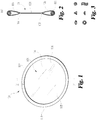
- retractor 100 can comprise a frame 102 and a membrane 104 wrapped around portions of the frame 102 in a wrapped area 106, to secure the membrane 104, as shown in FIGs. 1-2 .
- the frame 102 can be a deformable frame capable of deformation in one or more directions while maintaining the structural integrity 102 of the frame.
- the frame 102 is a deformable resilient frame that is capable of being deformed in one or more directions with a propensity to recover to an undeformed and/or lesser deformed configuration.
- the frame 102 may have a shape-memory.
- portions of the frame 102 may comprise shape memory materials, such as a shape memory alloy such as NiTi to name one non-limiting example.
- the membrane 104 can comprise a material formed into a sheet and/or film-like arrangement. Other variations are also contemplated.
- the membrane 104 can comprise a series of elongated members, such as fibers, extending between portions of the frame 102, across the central opening 109. In some instances, elongated members extending across portions of the central opening 109 extend from a portion of the frame 102 to another elongated member, forming a mesh-like arrangement.
- the membrane 104 has a thickness substantially less than that of the frame 102. However, other variations are contemplated. For example, the membrane 104 and the frame 102 may have substantially the same thickness, or the membrane 104 may have a substantially greater thickness than that of the frame 102.
- the wrapped area 106 of the membrane 104 can have sealing lines 108 securing portions of the membrane 104 to itself and portions of the membrane 104 around the frame 102.
- sealing lines 108 can correspond with locations of heat bonding and/or adhesive bonding of the membrane 104 that form the wrapped portion of the membrane 104 extending around the frame 102 and securing the membrane 104 to the frame 102.
- the frame 102 comprises an elongated body following a path that defines a central opening 109.
- frame 102 can comprise a relatively thin-walled member that forms the central opening 109 across which the membrane 104 extends.
- the retractor 100 can optionally have a segment 110 of the frame 102 that is free of attachment to the membrane 104. This segment 110 may leave expansion room for the membrane 104 during, for example, the deformation process of the retractor 100. Additionally, segment 110 may allow for a portion of the frame 102 to telescopically slide within another portion of the frame 102, so as to allow the size and/or shape of the frame 102 and/or central opening 109 to change.
- the membrane 104 can be attached completely around the frame 102 in some embodiments.
- the frame 102 can form a closed structure around the central opening 109 or an open structure, following less than the perimeter of the central opening 109.
- the frame 102 can form a planar arrangement in its relaxed position, or the relaxed position of the frame 102 can form a non-planar convex shape.
- the perimeter formed by the frame 102 provides for attachment of the membrane 104 across the central opening 109 or a suitable portion thereof.
- the membrane 104 may or may not be attached to itself and/or to the frame 102 at all portions of the perimeter of the central opening 109.
- the membrane 104 is attached around substantially all of the perimeter.
- FIG. 2 A cross sectional view through the retractor 100 of FIG. 1 along the 2-2 line is illustrated in FIG. 2 .
- the membrane 104 is wrapped around the frame 102 in the wrapped area 106 and is secured to itself by sealing lines 108.
- the frame 102 has a circular or round cross-section, as illustrated in FIG. 2 .
- the frame 102 may have a number of cross-sectional shapes at portions along the length of the frame 102 such as triangular, oval, pentagonal, wavy rectangular, semi-circular, or circular with hollow, as shown in FIG. 3 .
- any reasonable cross sectional shape of the frame 102 can be used.
- Frame 102 having a triangular and/or wavy rectangular cross section may provide better self-retaining properties for the retractor 100 once the retractor 100 is deployed, as the triangular and/or wavy rectangular cross-section may provide greater latch when in contact with wall of the body cavity. Additionally, in the embodiments where the cross-sectional shape of the frame 102 is semi-circular or triangular, twisting and folding the semi-circular or triangular frame 102 into a two layer configuration, as illustrated in FIG. 6b , results in a circular or diamond cross sectional profile, which further assists in inserting the retractor 100 into the abdominal incision.
- the cross section of the frame with a circular cross section can measure from about 0.1 cm to about 3 cm in diameter, in some embodiments from about 0.25 to about 2.5 cm, and in additional embodiments about 0.5 cm to about 2 cm in diameter.
- the size of the cross section is more easily defined with the perimeter instead of diameter.
- the frame can have a perimeter around a cross section of the frame of about 0.25 cm to about 10 cm, in some embodiments of about 0.5 cm to about 8 cm, and in additional embodiments of about 1 cm to about 6 cm.
- the membrane 104 is coupled to the frame 102 using a coupling member such as an adhesive and/or heat sealing techniques, although other techniques known in the art may also be used.
- the membrane 104 may wrap around the frame 102 and attach or seal to itself as shown in FIGs. 1 and 2 .
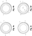
- the wrap around configuration with various sealing methods is further illustrated by schematic diagrams in FIGs. 4a-d .
- membrane 134 wraps around frame 132 creating a wrapped around area 136 around the frame 132 that is secured by sealing line 138 , which is the point of attachment of the membrane 134 onto itself, such as via adhesive or heating of the membrane 134 material.
- the sealing line 138 may be created with stitches 140 as shown in FIG.
- the membrane 134 can be directly attached to the material of the frame 132.
- the membrane 134 material can be glued, heat bonded, stitched and/or stapled directly to the frame 132.
- the membrane 134 can be attached around a majority of the perimeter of the frame 132, although the membrane 134 may be attached around the entire perimeter of the frame 132.
- the frame of the retractor in general can be composed of resilient, flexible material to permit twisting, bending, and generally deformation of the retractor. Padding or cushion can be added around the frame to improve traction between the retractor and the wall of the body cavity while preventing applying excess pressure to cause injury to the tissue of the cavity.
- the frame can be formed from one or more biocompatible materials, including, for example, metals, such as stainless steel or alloys, e.g., Nitinol®, or polymers such as polyether-amide block co-polymer (PEBAX®), nylon (polyamides), polyolefins, polyesters, polycarbonates or other suitable biocompatible polymers including elastomeric polymer, such as suitable polyurethanes, polydimethyl siloxane, acrylonitrile butadiene styrene (ABS), high density polyethylene (HDPE), rubber, polyisoprene (i.e., synthetic rubbers), and polytetrafluoroethylene.
- metals such as stainless steel or alloys, e.g., Nitinol®
- polymers such as polyether-amide block co-polymer (PEBAX®), nylon (polyamides), polyolefins, polyesters, polycarbonates or other suitable biocompatible polymers including elastomeric polymer,
- a metal frame can be covered in a polymeric cover or the like.
- different portions of frame can be formed from different materials to introduce desired stiffness/flexibility for the particular portion of the frame.
- the frame can be made from polymer embedded with metal wire. Suitable polymers include, for example, polyamides, i.e., nylons.
- the metal wire can be braided, coiled or otherwise placed over a polymer tubing liner with some tension.
- a polymer jacket can be then placed over the top of metal wire or the like. Upon heating over the softening temperature of the polymer and subsequent cooling, the wire becomes embedded within the polymer.
- the liner and jacket can be the same or different materials.
- the wire adds additional mechanical strength while maintaining appropriate amounts of flexibility.
- the frame is made of material that has sufficient resilience to substantially regain its resting configuration after being deformed, which is self-extendable.
- the frame may be a durometer from about 40 A to about 90 A on the A durometer scale or from about 50 D to about 90 D on the D durometer scale, as specified in ASTM protocol D2240-00.
- Frames formed from elastic polymers, such as rubbers or the like, can be convenient and relatively inexpensive.
- the membrane can be constructed from a biocompatible sheet, fabric, net, or a combination thereof.
- the membrane may be made out of transparent or semitransparent materials, such as polymers.
- FIG. 4d shows a schematic diagram of a round shaped retractor with perforations 112 on the membrane.
- the membrane can alternatively be constructed from material that can be punctured by medical instruments such as a laparoscope to gain better visualization from trochar sites proximal to the retractor.
- the membrane may be clear, transparent, translucent, opaque and made of a variety of different materials with different characteristics.
- the membrane can be made from an elastomer such as polyisoprene, polyurethane, silicone polyurethane, or silicone.
- the membrane may be non-elastic or slightly elastic so that the membrane can restrain organs or other body portions without significantly distending the membrane.
- inelastic materials such as polyethylene terephthalate can be used to form the membrane or portions thereof.
- the thickness of the membrane may vary, for example, from about 0.005 inches (0.0127 cm) to about 0.1 inches (0.254 cm) and in some embodiments of about 0.01 inches (0.0254 cm) to about 0.05 inches (0.127 cm).
- a person of ordinary skill in the art will recognize that additional ranges of thickness within the explicit ranges above are contemplated and are within the present disclosure.
- the membrane in general is foldable and has sufficient strength to retain organ while being extended across the central opening and/or around the frame.
- the retractor can be made of disposable materials, such that the retractor may be thrown away after use, although the retractor can be made of a durable, reusable material in some embodiments.
- the resilient nature of the frame permits twisting and folding of the retractor to allow insertion into small abdominal wall incisions, and permits the retractor to conform to the inner contours of the inner aspect of the patient's abdomen to effectively retract bowel away from the surgical field.
- Clinical experience has demonstrated that during open abdominal laparotomy in an approximately 70 kg male the abdominal cavity measures approximately 6-8 inches (15, 2-20,3 cm) in anterior to posterior (A-P) plane and 10-12 inches (25,4-30,5 cm) in lateral plane.
- the natural or "resting" dimensions of the retractor can have a suitable diameter of approximately 6 to 20 inches (15,2-50,8 cm), in some embodiments from about 8 to about 18 in (20,3 to about 45,7 cm) and in additional embodiments from about 10 to about 16 inches (25,4 to about 40,6 cm) in diameter.
- the resting A-P dimensions within the patient can be from about 2 to about 12 inches (5,1 to about 30,5 cm), in some embodiments from about 4 to about 10 inches (10,2 to about 25,4 cm) and in further embodiments from about 6 to about 8 inches (15,2 to about 20,3 cm).
- Lateral dimensions, across the patient, of a generally non-planar convex shaped retractor within the patient can be about 6 to about 20 inches (15,2 to about 50,8 cm), in further embodiments from about 8 to about 18 inches (20,3 to about 45,7 cm), and in other embodiments form about 10 to about 16 inches (25,4 to about 40,6 cm).
- a person of ordinary skill in the art will recognize that additional dimensional ranges within the explicit ranges above are contemplated and are within the present disclosure.
- A-P peritoneal dimensions are 9-12 inches (22,9-30,5 cm) and lateral dimensions are 10-12 inches (25,4-30,5 cm).
- the lateral dimensions are similar to open cases, since laparoscopic insufflations of the abdomen increases the A-P dimension much more than the lateral dimensions, which stays reasonably unchanged.
- the natural or "resting" dimensions of the retractor has a diameter from about 6 to about 24 inches (15,2 to about 61 cm), in further embodiments from about 8 to about 20 (20,3 to about 50,8) and in other embodiments from about 10 to about 16 inches (25,4 to about 40,6 cm).
- the resting A-P dimensions can be in some embodiment from about 6 to about 20 inches (15,2 to about 50,8 cm), in further embodiments from about 8 to about 18 inches (20,3 to about 45,7 cm) and in other embodiment from about 9 to about 14 inches (22,9 to about 35,6 cm).
- Lateral dimensions for a generally ovoid retractor within the patient would be approximately the same as for an "open" version of the retractor i.e., from about 6 to about 20 inches (15,2 to about 50,8 cm), in further embodiments from about 8 to about 18 inches (20,3 to about 45,7 cm) and in additional embodiments from about 10 to about 16 inches (25,4 to about 40,6 cm).
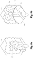
- planar retractor shapes such as square, rectangle, oval, oblong, bean, and "U" or horse shoe or composite shape shown in FIG. 5 a - ⁇ , can be adopted. Some of these frame shapes form a closed structure around the interior.
- the frame of the "U" or horse shoe shaped retractor does not surround the perimeter of the membrane and has an opening area 122 that can be more easily deformed than other parts of the retractor.
- the retractor can be made with a frame that is non-planar in its resting or natural configuration.
- An example of a non-planar convex circular retractor is shown in FIG. 5 g , although retractors with other shapes can be made three dimensionally convex also.
- the degree of curvature out of the plane can be selected to suit desired properties of the retractor.
- the non-planar convex shaped retractor may be desirable in some applications, as the retractor may or may not rely on the interaction between the wall and the frame only to create the convex shape for restraining the organs within the patient.
- the dimensions of the frame of a non-planar retractor can be evaluated by distorting the frame to a planar configuration for the measurements, and then the measurements described above for the naturally planar retractors can be applied to the non-planar designs.
- the retractor can be made of various sizes and configurations for use in various size humans and animals depending on the size and weight of the individual (e.g. small, medium and large), body habitus, prior abdominal surgery, size and dimensions of the peritoneal cavity, and whether open vs. laparoscopic surgery is being performed.
- the concavity of a bean shaped retractor may be placed over retroperitoneal vessel and/or conduit to prevent compression or occlusion of the vessel and/or conduit.
- the size of the retractor is more conveniently defined with the perimeter instead of diameter.
- the retractor can have a perimeter from about 5 to about 200 inches (12.7 to 508 cm), in some embodiments from about 10 to about 150 inches (25.4 to 381 cm), in additional embodiments from about 20 to about 100 inches (50.8 to 254 cm).
- a person of ordinary skill in the art will recognize that additional ranges of perimeter within the explicit ranges above are contemplated and are within the present disclosure.
- portions of the retractor 100 are arranged for complete disposal within the body of a patient (e.g., beneath the skin of the patient).
- the frame 102 of the retractor 100 is arranged for complete disposal within the abdomen of a patient.
- some embodiments of the present disclosure lack a portion that extends outside of the body of the patient.
- the deformable resilient frame lacks a portion that extends outside of the body of the patient, such as a handle.
- insertion and/or retrieval portions of the retractor 100 and/or an accessory may extend to a position outside of the body of the patient (e.g., extending through the abdominal wall and the skin of the patient to a position outside of the patient's skin).
- the retractor may additionally be combined with other surgical instruments such as a wound retractor or a laparoscopic access device.
- the retractor may affix to the proximal aspect of an abdominal wound retractor such as the "Alexis" retractor by Applied Medical, hand-assisted laparoscopic access devices such as the "Gelport” also from Applied Medical, or the "Dextrus” hand access device from Ethicon Endosurgery.
- the wound retractor and the access devices commonly has an inner plastic or polymer ring that can partially retain the retractor in the abdominal wound.
- the retractor described herein may attach to a selected location of the ring of the wound access device using an approximately clip-on attachment which attaches the retractor to the inner ring of the abdominal wound retractor.
- Such a clip-on attachment can attach around the inner ring, while not interfering, impinging or perforating the sleeve aspect of the abdominal wound retractor and retracts viscera into the upper abdomen.
- Various fasteners can be adapted for interfacing the surgical retractor described herein with the wound access retractor lower ring. The interfacing of the surgical retractor with the wound retractor provides for ability to obtain the advantages of both devices while limiting any interference between the devices.
- the retractor described herein can be made to be disposable items to avoid the need for subsequent cleaning and sterilization.
- the generally sterile biocompatible retractor may additionally be coated with bacterialcidal or antiinflammatory agents to further prevent infection or other complication during the surgical procedure.
- the expandable retractor may be shaped into different sizes and shapes to be suitable to surgical cavities of difference shape and sizes.
- the expandable retractor can also provide versatility during the delivery as well as the deployment and retrieval processes.
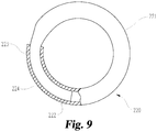
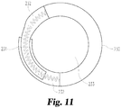
- an expandable retractor 220 comprises a tubular ring 221 with one end 222 of the tubular ring 221 having a slightly smaller diameter than the opposite end 223.
- the smaller diameter end 222 of the tubular ring 221 is inserted into the larger diameter end 223 to have a slidably overlapping section 224 to create a generally circular ring.
- the overlapping section 224 may be large or small. In some embodiments, the overlapping section 224 can comprise part or more than 50% circumferences of the tubular ring 221.
- the expandable retractor 220 contracts in size. Conversely, the smaller end 222 may be withdrawn out of the larger tubular member end 223 to reduce or diminish the overlapping section 224 to create an expandable retractor 220 with a larger diameter and surface area.
- the retractor ring comprises a series of segments of tubular members with incrementally decreasing diameters, wherein the transition from a larger to a smaller diameter is by means of a "step down” or “shoulder” from the larger to the smaller diameter segment.
- the "step downs” or “shoulders” are also present on the smaller diameter end of the retractor ring.
- the retractor ring may be expanded serially from one "step down” or “shoulder” to the next, and the ring will be held in place by means of the shoulders abutting against each other to prevent the ends of the ring from slipping within each other and loss of retractor diameter to keep the retractor in a pre-determined expanded diameter.
- This embodiment may be manufactured by inserting a plurality of tubular members within each other, wherein the outer diameter of the smaller member is the same as the inner diameter of the larger tubular member. Having inserted the smaller diameter member within the larger diameter member the members are affixed. This is repeated a plurality of times resulting in a series of tubular members of decreasing inner and outer diameters, wherein the "step down" or "shoulders" on the inner and outer aspects are staggered along the length of the final tubular structure. The smaller diameter end of the resulting tubular device is then inserted into the larger diameter end, resulting in a ring device. As the ring is expanded, it is held in place by the outer and inner "shoulders" abutting against each other.
- ratchets located at points along the circumference of the outer and inner tubular member.
- This "ratchet” configuration holds the inner and outer tubular member at a given diameter, and prevents the inner tube from unintentionally advancing further into the outer tubular member and thereby decreasing the diameter of the retractor.
- the “ratchet” mechanism therefore holds the retractor ring at any pre-determined diameter, so facilitating retraction of the peritoneal contents.
- all or part of the tubular member 225 may be hollow.
- An insert 226, such as a reinforcing member, can be used to add the required properties of malleability flexibility or shape memory properties to the tubular member 225.
- the insert 226 may be present throughout part or all of the circumference of the outer tubular member 225 or throughout a portion of the hollow outer ring, depending on whether the hollow outer ring is fully contracted and/or closed (i.e. smallest diameter) or fully expanded (i.e. largest diameter).
- the midpoint 227 of the insert 226 and the midpoint 228 of the tubular member 225 are located preferably 30-330 degrees apart, more preferably 90-270 degrees apart or most preferably approximately 180 degrees apart, to prevent the disruption of the retractor.
- the insert 226 may also be partially or completely hollow to allow the ends of the insert 226 to slide in and out as the retractor is contracted, expanded, closed, and/or opened.
- Both or either the insert 226 and the tubular member 225 may be made of metal, polymer, or a combination thereof to have the desired flexibility malleability bending twisting or shape memory properties to provide the desired performance of the ring retractor as a whole.
- the retractor may assume different shapes in its contracted and/or expanded configurations.
- the retractor may be a circular shape in its contracted configuration, and expand into an oval configuration in the expanded configuration and/or as the retractor is expanded. Any combination or mixture of shapes may be provided as the retractor is expanded and contracted, in order to provide the desired size and shape retractor to provide the preferred retraction of the intra-abdominal organs in individual sized patients.
- the central opening and the membrane expand and contract as the outer ring is made larger and smaller or as the ring assumes a variety of different shapes.
- the membrane 229 is made of a rubber type material, similar to that found in elastic balloons, which freely expands and contracts. This expandability also provides the necessary flexibility of the membrane 229 to allow it to be folded and twisted into different shapes, for instance twisted into a figure-of-eight then folded upon itself to make a retractor approximately half of its original size.
- the retractor ring 230 may be expandable by a device or method such as a spring 231 located within the lumen of the outer ring 232 as described above.
- the ring 230 may expand by means of force exerted from a compressed spring 231 located within the outer ring 232 with corresponding increase in the surface area of the membrane 233 of the retractor.
- contraction of the ring 230 i.e., making the ring smaller results in compression of the contained spring 231.
- the contracted and/or closed retractor ring 230 is insertable into the abdomen, since this arrangement has a smaller maximum outer dimension than the expanded arrangement.
- the expandable retractors described herein can be delivered or deployed using the push-and-hook device and methods described below.
- the expandable retractor may be twisted into a figure-of-eight and folded upon itself. After inserting the retractor into the abdomen the retractor "unfurls" to its planar form, and may then be further expanded by means of the contained mechanism, such as the spring 231 or insert 226, to further increase the surface area of the central opening and/or the membrane.
- the retractor Having inserted the ring retractor into the body cavity, the retractor “unfurls” to its resting shape, and may then be further “opened” or expanded by a combination of laparoscopic graspers, manually (as in hand assisted surgery) or a combination of both.
- protrusions are present at locations around the retractor ring which can be grasped by laparoscopic instruments to facilitate opening or expanding the ring.
- the size the expandable retractor can be adjusted such as using the "shoulder" mechanism described above.
- Alternative embodiments include other means of expanding the ring such as infusion of gas or liquid into the lumen of the ring, so expanding the diameter of the ring.
- Alternative embodiments include a method or device to automatically open the ring, such as a "release" mechanism incorporated into the outer ring and spring interface. Pressing the release mechanism then allow the spring to open and thereby widen or expand the retractor ring.
- a push-and-hook type of device (hereinafter the PH device) can be used to facilitate the delivery and retrieval of the surgical retractors of interest during surgical procedures.
- the PH device can be used to elongate the profile of a retractor so the retractor can be inserted through a trochar. Once inserted, the retractor is released to retract organ. After the completion of the surgical procedure, the retractor can be retrieved with the PH device through the trochar.
- the PH device may be used to twist the retractor before the twisted retractor can be delivered. Referring to FIG.
- the PH device 300 has a shaft 302 comprising a proximal end region 303, a distal end region 304, and a retractor coupling portion 305.
- the retractor coupling portion 305 comprises an inserting portion 306 arranged to insert a portion of the retractor 100.
- the inserting portion 306 comprises a recess arranged to receive a portion of the retractor 100.
- the inserting portion 306 may comprise an "n" shaped pusher hook 307 that can be used to push a retractor through a trochar 400 during the insertion or delivery process.
- the retractor coupling portion 305 comprises a retrieving portion 308 arranged to retrieve a portion of the retractor 100 from inside of the body of a patient, such as retrieving a portion of the retractor 100 into and/or out of the trochar 400.
- the retrieving portion 308 is proximal to the insertion portion 306, such as the "n" shaped hook 307. Additionally, or alternatively, similar to the inserting portion 306, the retrieving portion 308 can comprise a recess arranged to receive a portion of the retractor 100.
- the retrieving portion 308 comprises a "u" shaped retrieval hook that can be used to retrieve the retractor 100 and, in some cases, pull it out from the surgical cavity via the trochar 400.
- the diameter, shape and size of inserting portion 306 and/or retrieving portion 308 and/or hooks 307 and 309 can be the same or slightly larger than the diameter of the frame 102 of the retractor 100.
- the peripheral frame 102 of the retractor 100 can have a maximum diameter of 5mm, and optionally a hemispherical cross-section such that two sections of the frame 102 can be brought together to roughly form a spherical cross section with a corresponding small overall cross section in the deformed configuration. As shown in Figs.
- the PH device 300 consisting of the shaft 302 (in some instances 1mm diameter) is detachably affixed in the coupling portion 305 of the distal end region 304 to the frame 102 via the inserting portion 306, such as the coupling "n" shaped hook 307, and can simply push a portion of the retractor 100 through the operative trochar 400 into the peritoneal cavity.
- the retractor 100 exits the distal end region of the trochar 400 it can open up to provide retraction of the abdominal contents, and the PH device 300 is simply removed from the trochar 400.
- a hemispherical cross section of the frame 102 of the rectractor 100 can form a generally circular profile when portions of the frame 102 are brought into adjacent position, such as when the retractor is compressed within the operative trochar 400, so as to reduce the cross-sectional surface area of the retractor 100.
- the membrane 104 of the retractor 100 When pushed into the operative trochar 400, the membrane 104 of the retractor 100 is compressed and/or sandwiched between the two opposing portions of the frame 102 of the retractor 100.
- the membrane 104 of the retractor 100 may be wrapped around the frame 102 of the retractor 100 when the retractor 100 is in a collapsed configuration.
- the PH device 300 is reinserted into the abdomen via the trochar 400 and the retrieving portion 308 of the coupling portion 305, such as the "u" shaped retrival hook 309, at the distal end region 304 of the PH device 300 couples to a portion of the frame 102 of the retractor 100 to pull the retractor 100 out of the abdomen through the trochar 400.
- the retrieving portion 308 of the coupling portion 305 such as the "u" shaped retrival hook 309
- the frame 102 of a retractor 100 has a maximum diameter of 5mm. Additionally, in some instances, it may be preferable that the frame 102 have a hemispherical cross-section.
- the retractor 100 can be twisted around a PH device 300 to form a helical arrangement, sometimes referred to as a "twizzler" shape, to minimize the maximum outer dimension of the retractor 100. Referring to FIG. 14 , similar to the PH device 300 of FIG.
- the distal end region 304 of the PH device 300 has a coupling portion 305 that may comprise hooks 307 and 309 located at and/or near the distal tip of the PH device 300.
- the coupling portion 305 is arranged for twistable coupling of the retractor 100 to the PH device 300 such that one or more portions of the retractor 100 may be twisted and/or rotated with respect to the PH device 300 when a portion of the retractor 100 is coupled to the PH device 300.
- an inverted (“n" shaped) hook 307 arranged to stabilize a distal aspect of the retractor 100 during twisting of the frame 102 and/or to push a portion of the retractor 100 through a trochar 400 during insertion into the body of a patient (e.g., beneath the skin of a patient).
- the frame 102 of the retractor 100 is extended and/or stretched proximally substantially along the axis of the shaft 302 of the PH device 300 so as to configure the retractor 100, including frame 102, into an elongated profile.
- the proximal end 314 of the frame 102 is rotated in a clockwise or anti-clockwise direction 315, while the distal end 316 is prevented from rotating by means of the coupling portion 305 such as hook 307 located near and/or at the tip of the shaft 302 of the PH device 300.
- the twisting is continued until the retractor 100 has been satisfactorily elongated in its axial plane and contracted and/or compressed in its maximum outer dimension in the transverse plane, such as by a decreased cross-sectional surface area.
- the resulting configuration resembles a helically wound, sometimes referred to as a "twizzler", configuration 317, as shown in FIG. 16 .
- the frame 102 of the retractor 100 forms a double helix that extends along a length of the PH device 300.
- the twisting can be accomplished by any means apparent to one of ordinary skill in the art, such as by a rotatable screw and/or a threaded device 318 located on the proximal aspect of the shaft 302.
- the screw and/or knob 318 may be made unidirectional by means of ratchets to prevent unfurling of a portion of the retractor 100 such as the frame 102.
- the frame 102 of the retractor 100 is stretched and/or extended proximally substantially along the axis of the shaft 302, to make an elongated profile.
- the distal end 316 of the frame 102 is then rotated in a clockwise or anti-clockwise direction 315 around the shaft 302 of the PH device 300, whilst the proximal end 314 is prevented from rotating around a portion of the PH device 300.
- the frame 102 is stretched and/or extended proximally substantially along the axis of the shaft 302, to make an elongated profile.
- the proximal end 314 of the frame 102 is then rotated in a clockwise or anti-clockwise direction 315, whilst the distal end 316 is rotated in the opposite direction.
- the distal end 316 is simply advanced (e.g., pushed) through the operative access device, such as a trochar 400, whereupon it opens up in the peritoneal cavity once it exits the distal end of the access device, e.g., trochar 400.
- the triangular or hemispherical cross section profile of the frame 102 forms a generally circular profile when the frame 102 is twisted into its helically-coiled shape, so as to reduce the cross-sectional surface area.
- the membrane 104 of the retractor 100 is compressed and/or sandwiched between the two opposing sides of the frame 102 of the retractor 100.
- the membrane 104 of the retractor 100 may be wrapped around the frame 102 of the retractor 100 in its stretched and/or extended configuration when advanced (e.g., pushed) into the operative access device (e.g., trochar 400).
- the PH device 300 is readvanced and/or reinserted into the operative access device and the retrieving portion 308 of the coupling portion 305, such as the "u" shaped retrieval hook 309 at and/or near the tip of the pusher, couples and/or hooks a portion of the retractor 100, such as the frame 102, to retrieve (e.g., pull) it out of the abdominal cavity.
- the retractor is pre-assembled and inserted into an outer sheath or cylinder in a helically wound (e.g., "twizzler") configuration.
- the outer sheath or cylinder is slightly less than 12mm in diameter.
- No shaft 302 of the PH device 300 may be necessary in the final assembled product in this arrangement.
- the sheath-retractor assembly can be inserted into the operative trochar 400 and the retractor is simply advanced (e.g., pushed) out of the sheath by a simple pushing device.
- the retractor 100 may be retrieved in the same way as the embodiments described above.
- the PH device 300 can be made of biocompatible metal, polymer or a combination thereof.
- the shaft 302, hooks 307 and/or 309, and knob can adopt any reasonable size with desirable physical integrity.
- the shaft 302 can have a diameter of about 1mm to 3 mm.
- the portions of the retractor 100 are arranged to receive portions of the PH device 300.
- the PH device 300 in general can be used to facilitate the delivery and/or retrieval of the retractors described herein.
- the PH device 300 in general can have a coupling portion 305 comprising an inserting portion 306 and/or a retrieving portion 308 arranged to insert and/or retrieve a portion of a retractor 100 into and/or out of the body of a patient (e.g., beneath the skin of a patient).
- the coupling portion 305 comprises a pusher hook 307 and/or a retrieval hook 309.
- the portions of the coupling portion 305 can be positioned at different locations on the shaft 302, not necessarily adjacent each other as shown in FIG. 12 . Additionally, the size, shape, and the number of the portions of the coupling portion 305, such as hook(s) 307 and/or 309 positioned at the distal end of the shaft of the PH device 300, may vary to suit different surgical needs. In some embodiments, the PH device 300 may have only one portion, such as inserting portion 306 and/or pusher hook 307, to facilitate the delivery of one or more retractors 100.
- the PH device 300 may have only a retrieving portion 308 in the coupling portion 305, such as one retrieval hook 309, to facilitate the retrieval of one or more retractors 100.
- the portions of the PH devices 300 such as the inserting portion 306, retrieving portion 308, "n" shaped pusher hook 307, and/or "u” shaped retrieval hook 309 can be used singly or in combination to facilitate the delivery and/or the retrieval processes of one or more retractors 100.
- one or more of the portions of the coupling portion 305 may be removable.
- the pusher hook 307 can be removed after being used to facilitate the delivery of one or more retractors 100, leaving only the retrieval hook 309 to be used in the retractor 100 retrieval process.
- the PH device 300 may start with fewer than all of the portions of the coupling portion 305, such as only the inserting portion 306 comprising pusher hook 307, to be used to facilitate the delivery of the retractors 100, and, upon completion of the delivery process, the inserting portion 306 is removed and a the retrieving portion 308 (e.g., retrieval hook 309) is adapted onto the shaft 302 of the PH device 300 so the PH device 300 is now suitable to facilitate the subsequent retrieval process.
- the shaft 302 of the PH device 300 in general is straight. Although curvature can be built into the shaft 302 to adapt the PH device 300 for appropriate surgical applications.
- the PH device 300 described herein can be used to facilitate the delivery and retrieval of retractors 100 through a variety of surgical openings and is not limited to be used in conjunction with trochar 400 only.
- a circular retractor can be used in abdominal surgeries by twisting the retractor into a folded shape, such as a figure-eight shape or other convenient folded shape.
- a figure eight shape formed from a circular retractor can be further folded upon itself to make it approximately half its original diameter.
- Non-circular shaped retractors can be similarly appropriately folded for insertion into the patient.
- the folded or deformed retractor can then be inserted into a small laparoscopic incision into the peritoneal cavity. Having inserted the retractor into the peritoneal cavity, the retractor "unfurls" and assumes substantially its original size and retracts small bowel out of the pelvic cavity.
- FIG. 6 a a circular retractor 100 of FIG.
- FIG. 6 b When released, the deformed retractor can substantially regain its resting configuration, and the particular resulting shape and size of the deformable retractor can conform to the peritoneal cavity into which it is placed.
- the resilient retractor when deformed can be inserted into smaller incisions than would otherwise be possible.
- the unfolding of the deformed retractor to assume substantially its original size inside a body cavity allows the retractor to push against the wall of the cavity to become self-retainable inside the cavity.
- the resiliency is generally not excessive so that the retractor does not injure any organs or the wall of the body cavity.
- the retractor can be compressed in the anterior-posterior (A-P) plane by pressure from the anterior abdominal wall into an ovoid shape, and further bent in the lateral plane into a convex or non-planar "U” form, by pressure from the lateral abdominal wall.
- the retractor is positioned for and capable to support organs in a vertical plan (e.g., preventing movement of organs along a superior to inferior direction and/or vice versa in the abdominal cavity).
- convex deployed configuration is discussed, it is understood that other deployed configurations such as planar or concave relative to the lower part of the patient are also contemplated and within the present disclosure.
- the resulting two dimensional pressures not only distribute the pressures substantially along the entire circumference of the retractor to reduce or prevent organ injury or excessive local pressure at any one location, but also maintain the retractor in place without additional external force or devices.
- the membrane expands in an anterior-posterior and lateral direction to serve as the retractor surface in the axial plane, which effectively occludes the abdominal cavity, retracts viscera out of the pelvis, and thereby prevents the small bowel from entering the surgical field.
- the retractor provides retraction in all three planes and is self retaining.
- a retractor that has a natural non-planar convex shape in the un-deformed or resting configuration.
- a non-planar convex shaped retractor When such a non-planar convex shaped retractor is released inside a body cavity, it regains substantially its convexity and pushes organs away to create desired working space.
- the great vessels in the retroperitoneum are not significantly impinged, compressed or obstructed.
- This use of the device avoids arterial insufficiency (which results from aortic compression) and also avoids impeding venous return (which results from vena caval compression), both of which can be potentially life threatening.
- the deployed circular retractor or other suitable device design avoids trauma to or compression of the retroperitoneal structures during sudden deflation of the abdomen, which can happen from time to time during laparoscopic surgery.
- the retractor simply distorts to a more ovoid shape exerting little or no additional force on the retroperitoneum or viscera. Additionally, the retractor avoids pressure necrosis or even perforation of small bowel or other delicate viscera. The reduction or elimination of compression or occlusion of the major blood vessels avoids a potential drop in blood pressure, which can be a life-threatening problem with metal mechanical retractors known in the art.
- the retractor may be bean shaped to provide the concavity of the bean over the retroperitoneum to further reduce compression of the great vessels.
- FIG. 8 a a schematic diagram of abdominal cavity 202 is shown with bowel loops 204 inside the pelvic cavity.
- a circular retractor placed inside the abdominal cavity is shown in FIG. 8 b , whereupon it gently "unfurls" to assume substantially its original size.
- the retractor assumes the contours of the inner aspect of the patients inner abdominal wall and forms a convex shape to effectively retract bowel loops into the upper abdominal cavity and prevent them from falling into pelvic cavity where surgery can be performed.
- a working space 208 is created inside the pelvic cavity exposing great vessels 206 .
- the retractor After completion of the surgery, the retractor is gently pulled out of the incision, and its flexible nature avoids any injury to the abdominal viscera or the incision itself. Once inside the abdominal cavity, the retractor is released and effectively retain organ. The working space created by the retractor is substantially free from the retained organs, thus providing improved access to surgical site of interest.
- the 3-D retractor can be rotated around the peritoneal cavity or around the inner ring of the abdominal wound retractor to provide access to the left colon or splenic flexure for the purpose of surgical mobilization, whilst still retracting the viscera out of the surgical field.
- the retractor is rotated counter-clockwise within the peritoneal cavity.
- the retractor may also be rotated or repositioned to enable mobilization of the right colon and hepatic flexure, again keeping the viscera out of the surgical field.
- the retractor is rotated clockwise within the peritoneal cavity.
- the lateral one thirds of a circular resting retractor may be individually “twisted” 180 degrees in their axial plane, preferably one in a clockwise and the other in a counter-clockwise manner
- a central ovoid When each lateral ovoids are released, they untwist in the opposite directions, when viewed end-on from one direction. Since both lateral ovoids are located at diametrically opposing ends of the central ovoid, the lateral ovoids "untwist" in a mirror image manner of each other.
- each lateral ovoid may then be folded 180 degrees to overlay the central ovoid, resulting in a 3-layer, generally circular or ovoid shape, one third of the original diameter.
- the 3-layer deformed retractor is inserted into peritoneal cavity, the two lateral one third "ovoids" unfurl laterally and untwist axially to assume the generally U shaped retractor configuration detailed above.
- the deployed retractor may also adopt a concave shape directing the bowel or other organs toward the head, or a planar shape inside the body cavity, which can be particularly effective for embodiments of membranes that are essentially not elastic.
- the aforementioned twisting and folding maneuver can be repeated a plurality of times, to further decrease the diameter of the retractor for example to one quarter, one eighth, or one sixteenth etc of the original resting configuration.
- This smaller configuration of the retractor facilitates insertion of the retractor into the peritoneal cavity via an abdominal wound retractor or hand assisted laparoscopic access retractor.
- the retractor can be used in conjunction with a SILS access device by Covidien or a plastic HALS retractor such as the "Dextrus" by Ethicon Endosurgery, or with the "Lexus” HALS retractor made by Applied Medical. This combination provides much improved surgical exposure and is highly desirable during laparoscopic surgeries.
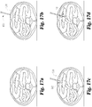
- FIGs. 17a-g illustrate the abdominal cavity of a patient as viewed along a inferior to superior direction.
- an access device such as a trochar 400 is advanced towards the outer surface of the skin 500 of a patient.
- the trochar 400 gains access to the abdominal cavity 502.
- a retractor system 50 comprising a retractor and/or an accessory such as a push-and-hook type delivery device can then be advanced through a lumen of the trochar 400.
- the retractor system 50 is advanced substantially along an anterior to posterior direction.
- the retractor 100 is released and one or more portions of the retractor 100, such as the frame 102, self-extend so as to spread the membrane 104 into a spread-open configuration.
- any delivery device associated with the retractor system 50 such as the PH device 300 may be withdrawn from the abdominal cavity through the lumen defined by the trochar 400, to a position outside of the body.
- a lumen of the trochar can also be used to perform additional surgical procedures.
Landscapes
- Health & Medical Sciences (AREA)
- Life Sciences & Earth Sciences (AREA)
- Surgery (AREA)
- Heart & Thoracic Surgery (AREA)
- Engineering & Computer Science (AREA)
- Biomedical Technology (AREA)
- Nuclear Medicine, Radiotherapy & Molecular Imaging (AREA)
- Medical Informatics (AREA)
- Molecular Biology (AREA)
- Animal Behavior & Ethology (AREA)
- General Health & Medical Sciences (AREA)
- Public Health (AREA)
- Veterinary Medicine (AREA)
- Surgical Instruments (AREA)
Claims (13)
- Écarteur biocompatible (100, 220), comprenant :un corps d'écarteur comprenant un cadre résilient déformable (102, 221, 225, 230) délimitant une ouverture centrale (109) et une membrane déformable (104, 229, 233) accouplée audit cadre résilient déformable et s'étendant en travers d'une partie de ladite ouverture centrale ;une première extrémité (223) dudit cadre résilient déformable délimitant une première lumière conçue pour accueillir une seconde extrémité (222) dudit cadre résilient déformable et accouplée coulissante à ladite seconde extrémité dudit cadre résilient de sorte que ledit cadre résilient déformable soit conçu pour faire varier la taille de l'ouverture centrale et soit conçu pour terminer l'installation dans le corps d'un patient ; etdans lequel ledit cadre résilient déformable est autodéployable et est susceptible de s'autodéployer depuis une configuration contractée vers une configuration déployée.
- Écarteur biocompatible selon la revendication 1, comprenant :un élément de sollicitation (231) accouplant des première et seconde parties dudit cadre résilient déformable.
- Écarteur biocompatible selon la revendication 2, dans lequel :ledit élément de sollicitation (231) comprend un ressort.
- Écarteur biocompatible selon l'une quelconque des revendications 2 et 3, dans lequel :ledit élément de sollicitation (231) est positionné à l'intérieur dudit cadre résilient.
- Écarteur biocompatible selon l'une quelconque des revendications 2 à 4, dans lequel :ledit élément de sollicitation (231) sollicite lesdites première et seconde parties à l'opposé l'une de l'autre.
- Écarteur biocompatible selon l'une quelconque des revendications précédentes, comprenant en outre :un élément inséré (226) accouplé audit cadre résilient déformable.
- Écarteur biocompatible selon la revendication 6, dans lequel :ledit élément inséré (226) est positionné à l'intérieur dudit cadre résilient.
- Écarteur biocompatible selon l'une quelconque des revendications précédentes, dans lequel :ledit corps d'écarteur peut être configuré entre une configuration contractée et une configuration déployée conçues pour rétracter des tissus.
- Écarteur biocompatible selon la revendication 8, dans lequel :ledit corps d'écarteur est sollicité dans ladite configuration déployée.
- Écarteur biocompatible (100, 220) destiné à une insertion sous la peau d'un patient, comprenant :un corps d'écarteur comprenant un cadre résilient déformable (102, 221, 225, 230) délimitant une ouverture centrale (109) et une membrane déformable (104, 229, 233) accouplée audit cadre résilient déformable et s'étendant en travers d'une partie de ladite ouverture centrale ;une première extrémité (223) dudit cadre résilient déformable délimitant une première lumière conçue pour accueillir une seconde extrémité (222) dudit cadre résilient déformable et accouplée coulissante à ladite seconde extrémité dudit cadre résilient de sorte que ledit cadre résilient déformable puisse être configuré entre une configuration contractée et une configuration déployée conçues pour rétracter un tissu ;dans lequel ladite configuration contractée est conçue pour une insertion laparoscopique à travers la peau d'un patient ;dans lequel ledit cadre résilient déformable dans ladite configuration déployée est conçu pour une installation complète à l'intérieur du corps d'un patient ; etdans lequel ledit cadre résilient déformable (102, 221, 225, 230) est autodéployable depuis ladite configuration contractée vers ladite configuration déployée.
- Écarteur biocompatible selon la revendication 10, dans lequel :ledit cadre résilient déformable (102, 221, 225, 230) dans ladite configuration contractée comprend un agencement allongé.
- Écarteur biocompatible selon l'une quelconque des revendications 10 et 11, dans lequel :ledit cadre résilient déformable (102, 221, 225, 230) dans ladite configuration contractée est enroulé en hélice.
- Écarteur biocompatible selon la revendication 12, dans lequel :ledit cadre résilient déformable (102, 221, 225, 230) dans ladite configuration contractée forme une double hélice.
Applications Claiming Priority (2)
| Application Number | Priority Date | Filing Date | Title |
|---|---|---|---|
| US201161507166P | 2011-07-13 | 2011-07-13 | |
| PCT/US2012/046733 WO2013010107A2 (fr) | 2011-07-13 | 2012-07-13 | Ecarteur chirurgical |
Publications (2)
| Publication Number | Publication Date |
|---|---|
| EP2731508A2 EP2731508A2 (fr) | 2014-05-21 |
| EP2731508B1 true EP2731508B1 (fr) | 2018-02-28 |
Family
ID=46598967
Family Applications (1)
| Application Number | Title | Priority Date | Filing Date |
|---|---|---|---|
| EP12741176.7A Active EP2731508B1 (fr) | 2011-07-13 | 2012-07-13 | Dispositif écarteur chirurgical |
Country Status (3)
| Country | Link |
|---|---|
| US (1) | US9521996B2 (fr) |
| EP (1) | EP2731508B1 (fr) |
| WO (1) | WO2013010107A2 (fr) |
Families Citing this family (408)
| Publication number | Priority date | Publication date | Assignee | Title |
|---|---|---|---|---|
| US20070084897A1 (en) | 2003-05-20 | 2007-04-19 | Shelton Frederick E Iv | Articulating surgical stapling instrument incorporating a two-piece e-beam firing mechanism |
| US9060770B2 (en) | 2003-05-20 | 2015-06-23 | Ethicon Endo-Surgery, Inc. | Robotically-driven surgical instrument with E-beam driver |
| US11890012B2 (en) | 2004-07-28 | 2024-02-06 | Cilag Gmbh International | Staple cartridge comprising cartridge body and attached support |
| US8215531B2 (en) | 2004-07-28 | 2012-07-10 | Ethicon Endo-Surgery, Inc. | Surgical stapling instrument having a medical substance dispenser |
| US10159482B2 (en) | 2005-08-31 | 2018-12-25 | Ethicon Llc | Fastener cartridge assembly comprising a fixed anvil and different staple heights |
| US11246590B2 (en) | 2005-08-31 | 2022-02-15 | Cilag Gmbh International | Staple cartridge including staple drivers having different unfired heights |
| US11484312B2 (en) | 2005-08-31 | 2022-11-01 | Cilag Gmbh International | Staple cartridge comprising a staple driver arrangement |
| US7669746B2 (en) | 2005-08-31 | 2010-03-02 | Ethicon Endo-Surgery, Inc. | Staple cartridges for forming staples having differing formed staple heights |
| US7934630B2 (en) | 2005-08-31 | 2011-05-03 | Ethicon Endo-Surgery, Inc. | Staple cartridges for forming staples having differing formed staple heights |
| US9237891B2 (en) | 2005-08-31 | 2016-01-19 | Ethicon Endo-Surgery, Inc. | Robotically-controlled surgical stapling devices that produce formed staples having different lengths |
| US20070106317A1 (en) | 2005-11-09 | 2007-05-10 | Shelton Frederick E Iv | Hydraulically and electrically actuated articulation joints for surgical instruments |
| US8186555B2 (en) | 2006-01-31 | 2012-05-29 | Ethicon Endo-Surgery, Inc. | Motor-driven surgical cutting and fastening instrument with mechanical closure system |
| US7845537B2 (en) | 2006-01-31 | 2010-12-07 | Ethicon Endo-Surgery, Inc. | Surgical instrument having recording capabilities |
| US7753904B2 (en) | 2006-01-31 | 2010-07-13 | Ethicon Endo-Surgery, Inc. | Endoscopic surgical instrument with a handle that can articulate with respect to the shaft |
| US20110024477A1 (en) | 2009-02-06 | 2011-02-03 | Hall Steven G | Driven Surgical Stapler Improvements |
| US11278279B2 (en) | 2006-01-31 | 2022-03-22 | Cilag Gmbh International | Surgical instrument assembly |
| US20110290856A1 (en) | 2006-01-31 | 2011-12-01 | Ethicon Endo-Surgery, Inc. | Robotically-controlled surgical instrument with force-feedback capabilities |
| US11224427B2 (en) | 2006-01-31 | 2022-01-18 | Cilag Gmbh International | Surgical stapling system including a console and retraction assembly |
| US20120292367A1 (en) | 2006-01-31 | 2012-11-22 | Ethicon Endo-Surgery, Inc. | Robotically-controlled end effector |
| US8708213B2 (en) | 2006-01-31 | 2014-04-29 | Ethicon Endo-Surgery, Inc. | Surgical instrument having a feedback system |
| US11793518B2 (en) | 2006-01-31 | 2023-10-24 | Cilag Gmbh International | Powered surgical instruments with firing system lockout arrangements |
| US8820603B2 (en) | 2006-01-31 | 2014-09-02 | Ethicon Endo-Surgery, Inc. | Accessing data stored in a memory of a surgical instrument |
| US8992422B2 (en) | 2006-03-23 | 2015-03-31 | Ethicon Endo-Surgery, Inc. | Robotically-controlled endoscopic accessory channel |
| US8322455B2 (en) | 2006-06-27 | 2012-12-04 | Ethicon Endo-Surgery, Inc. | Manually driven surgical cutting and fastening instrument |
| US10568652B2 (en) | 2006-09-29 | 2020-02-25 | Ethicon Llc | Surgical staples having attached drivers of different heights and stapling instruments for deploying the same |
| US20080078802A1 (en) | 2006-09-29 | 2008-04-03 | Hess Christopher J | Surgical staples and stapling instruments |
| US8652120B2 (en) | 2007-01-10 | 2014-02-18 | Ethicon Endo-Surgery, Inc. | Surgical instrument with wireless communication between control unit and sensor transponders |
| US8684253B2 (en) | 2007-01-10 | 2014-04-01 | Ethicon Endo-Surgery, Inc. | Surgical instrument with wireless communication between a control unit of a robotic system and remote sensor |
| US11291441B2 (en) | 2007-01-10 | 2022-04-05 | Cilag Gmbh International | Surgical instrument with wireless communication between control unit and remote sensor |
| US11039836B2 (en) | 2007-01-11 | 2021-06-22 | Cilag Gmbh International | Staple cartridge for use with a surgical stapling instrument |
| US20080169332A1 (en) | 2007-01-11 | 2008-07-17 | Shelton Frederick E | Surgical stapling device with a curved cutting member |
| US20090001121A1 (en) | 2007-03-15 | 2009-01-01 | Hess Christopher J | Surgical staple having an expandable portion |
| US8893946B2 (en) | 2007-03-28 | 2014-11-25 | Ethicon Endo-Surgery, Inc. | Laparoscopic tissue thickness and clamp load measuring devices |
| US8931682B2 (en) | 2007-06-04 | 2015-01-13 | Ethicon Endo-Surgery, Inc. | Robotically-controlled shaft based rotary drive systems for surgical instruments |
| US11672531B2 (en) | 2007-06-04 | 2023-06-13 | Cilag Gmbh International | Rotary drive systems for surgical instruments |
| US7753245B2 (en) | 2007-06-22 | 2010-07-13 | Ethicon Endo-Surgery, Inc. | Surgical stapling instruments |
| US11849941B2 (en) | 2007-06-29 | 2023-12-26 | Cilag Gmbh International | Staple cartridge having staple cavities extending at a transverse angle relative to a longitudinal cartridge axis |
| US7866527B2 (en) | 2008-02-14 | 2011-01-11 | Ethicon Endo-Surgery, Inc. | Surgical stapling apparatus with interlockable firing system |
| US8758391B2 (en) | 2008-02-14 | 2014-06-24 | Ethicon Endo-Surgery, Inc. | Interchangeable tools for surgical instruments |
| US7819298B2 (en) | 2008-02-14 | 2010-10-26 | Ethicon Endo-Surgery, Inc. | Surgical stapling apparatus with control features operable with one hand |
| US9179912B2 (en) | 2008-02-14 | 2015-11-10 | Ethicon Endo-Surgery, Inc. | Robotically-controlled motorized surgical cutting and fastening instrument |
| US8636736B2 (en) | 2008-02-14 | 2014-01-28 | Ethicon Endo-Surgery, Inc. | Motorized surgical cutting and fastening instrument |
| US8573465B2 (en) | 2008-02-14 | 2013-11-05 | Ethicon Endo-Surgery, Inc. | Robotically-controlled surgical end effector system with rotary actuated closure systems |
| BRPI0901282A2 (pt) | 2008-02-14 | 2009-11-17 | Ethicon Endo Surgery Inc | instrumento cirúrgico de corte e fixação dotado de eletrodos de rf |
| US10390823B2 (en) | 2008-02-15 | 2019-08-27 | Ethicon Llc | End effector comprising an adjunct |
| US11272927B2 (en) | 2008-02-15 | 2022-03-15 | Cilag Gmbh International | Layer arrangements for surgical staple cartridges |
| US9005230B2 (en) | 2008-09-23 | 2015-04-14 | Ethicon Endo-Surgery, Inc. | Motorized surgical instrument |
| US8210411B2 (en) | 2008-09-23 | 2012-07-03 | Ethicon Endo-Surgery, Inc. | Motor-driven surgical cutting instrument |
| US11648005B2 (en) | 2008-09-23 | 2023-05-16 | Cilag Gmbh International | Robotically-controlled motorized surgical instrument with an end effector |
| US9386983B2 (en) | 2008-09-23 | 2016-07-12 | Ethicon Endo-Surgery, Llc | Robotically-controlled motorized surgical instrument |
| US8608045B2 (en) | 2008-10-10 | 2013-12-17 | Ethicon Endo-Sugery, Inc. | Powered surgical cutting and stapling apparatus with manually retractable firing system |
| US8517239B2 (en) | 2009-02-05 | 2013-08-27 | Ethicon Endo-Surgery, Inc. | Surgical stapling instrument comprising a magnetic element driver |
| BRPI1008667A2 (pt) | 2009-02-06 | 2016-03-08 | Ethicom Endo Surgery Inc | aperfeiçoamento do grampeador cirúrgico acionado |
| US8444036B2 (en) | 2009-02-06 | 2013-05-21 | Ethicon Endo-Surgery, Inc. | Motor driven surgical fastener device with mechanisms for adjusting a tissue gap within the end effector |
| US8220688B2 (en) | 2009-12-24 | 2012-07-17 | Ethicon Endo-Surgery, Inc. | Motor-driven surgical cutting instrument with electric actuator directional control assembly |
| US8851354B2 (en) | 2009-12-24 | 2014-10-07 | Ethicon Endo-Surgery, Inc. | Surgical cutting instrument that analyzes tissue thickness |
| US20110172495A1 (en) * | 2010-03-26 | 2011-07-14 | Armstrong David N | Surgical retractor |
| US8783543B2 (en) | 2010-07-30 | 2014-07-22 | Ethicon Endo-Surgery, Inc. | Tissue acquisition arrangements and methods for surgical stapling devices |
| US8360296B2 (en) | 2010-09-09 | 2013-01-29 | Ethicon Endo-Surgery, Inc. | Surgical stapling head assembly with firing lockout for a surgical stapler |
| US11298125B2 (en) | 2010-09-30 | 2022-04-12 | Cilag Gmbh International | Tissue stapler having a thickness compensator |
| US11812965B2 (en) | 2010-09-30 | 2023-11-14 | Cilag Gmbh International | Layer of material for a surgical end effector |
| US11849952B2 (en) | 2010-09-30 | 2023-12-26 | Cilag Gmbh International | Staple cartridge comprising staples positioned within a compressible portion thereof |
| US9364233B2 (en) | 2010-09-30 | 2016-06-14 | Ethicon Endo-Surgery, Llc | Tissue thickness compensators for circular surgical staplers |
| US8864009B2 (en) | 2010-09-30 | 2014-10-21 | Ethicon Endo-Surgery, Inc. | Tissue thickness compensator for a surgical stapler comprising an adjustable anvil |
| US9629814B2 (en) | 2010-09-30 | 2017-04-25 | Ethicon Endo-Surgery, Llc | Tissue thickness compensator configured to redistribute compressive forces |
| US9861361B2 (en) | 2010-09-30 | 2018-01-09 | Ethicon Llc | Releasable tissue thickness compensator and fastener cartridge having the same |
| US9839420B2 (en) | 2010-09-30 | 2017-12-12 | Ethicon Llc | Tissue thickness compensator comprising at least one medicament |
| US10945731B2 (en) | 2010-09-30 | 2021-03-16 | Ethicon Llc | Tissue thickness compensator comprising controlled release and expansion |
| US9386988B2 (en) | 2010-09-30 | 2016-07-12 | Ethicon End-Surgery, LLC | Retainer assembly including a tissue thickness compensator |
| US9232941B2 (en) | 2010-09-30 | 2016-01-12 | Ethicon Endo-Surgery, Inc. | Tissue thickness compensator comprising a reservoir |
| US8695866B2 (en) | 2010-10-01 | 2014-04-15 | Ethicon Endo-Surgery, Inc. | Surgical instrument having a power control circuit |
| US9149265B2 (en) | 2011-02-26 | 2015-10-06 | Abbott Cardiovascular Systems, Inc. | Hinged tissue support device |
| US8632462B2 (en) | 2011-03-14 | 2014-01-21 | Ethicon Endo-Surgery, Inc. | Trans-rectum universal ports |
| JP6026509B2 (ja) | 2011-04-29 | 2016-11-16 | エシコン・エンド−サージェリィ・インコーポレイテッドEthicon Endo−Surgery,Inc. | ステープルカートリッジ自体の圧縮可能部分内に配置されたステープルを含むステープルカートリッジ |
| US11207064B2 (en) | 2011-05-27 | 2021-12-28 | Cilag Gmbh International | Automated end effector component reloading system for use with a robotic system |
| US9072535B2 (en) | 2011-05-27 | 2015-07-07 | Ethicon Endo-Surgery, Inc. | Surgical stapling instruments with rotatable staple deployment arrangements |
| US9044230B2 (en) | 2012-02-13 | 2015-06-02 | Ethicon Endo-Surgery, Inc. | Surgical cutting and fastening instrument with apparatus for determining cartridge and firing motion status |
| BR112014024098B1 (pt) | 2012-03-28 | 2021-05-25 | Ethicon Endo-Surgery, Inc. | cartucho de grampos |
| JP6305979B2 (ja) | 2012-03-28 | 2018-04-04 | エシコン・エンド−サージェリィ・インコーポレイテッドEthicon Endo−Surgery,Inc. | 複数の層を含む組織厚さコンペンセーター |
| MX353040B (es) | 2012-03-28 | 2017-12-18 | Ethicon Endo Surgery Inc | Unidad retenedora que incluye un compensador de grosor de tejido. |
| US9101358B2 (en) | 2012-06-15 | 2015-08-11 | Ethicon Endo-Surgery, Inc. | Articulatable surgical instrument comprising a firing drive |
| US9289256B2 (en) | 2012-06-28 | 2016-03-22 | Ethicon Endo-Surgery, Llc | Surgical end effectors having angled tissue-contacting surfaces |
| US11202631B2 (en) | 2012-06-28 | 2021-12-21 | Cilag Gmbh International | Stapling assembly comprising a firing lockout |
| US9204879B2 (en) | 2012-06-28 | 2015-12-08 | Ethicon Endo-Surgery, Inc. | Flexible drive member |
| US9649111B2 (en) | 2012-06-28 | 2017-05-16 | Ethicon Endo-Surgery, Llc | Replaceable clip cartridge for a clip applier |
| US20140001231A1 (en) | 2012-06-28 | 2014-01-02 | Ethicon Endo-Surgery, Inc. | Firing system lockout arrangements for surgical instruments |
| BR112014032776B1 (pt) | 2012-06-28 | 2021-09-08 | Ethicon Endo-Surgery, Inc | Sistema de instrumento cirúrgico e kit cirúrgico para uso com um sistema de instrumento cirúrgico |
| EP2866686A1 (fr) | 2012-06-28 | 2015-05-06 | Ethicon Endo-Surgery, Inc. | Verrouillage de cartouche d'agrafes vide |
| US20140001234A1 (en) | 2012-06-28 | 2014-01-02 | Ethicon Endo-Surgery, Inc. | Coupling arrangements for attaching surgical end effectors to drive systems therefor |
| WO2014110209A1 (fr) * | 2013-01-09 | 2014-07-17 | Cook Medical Technologies Llc | Écarteur abdominal |
| US9486132B2 (en) * | 2013-01-17 | 2016-11-08 | Abbott Cardiovascular Systems, Inc. | Access device for accessing tissue |
| BR112015021098B1 (pt) | 2013-03-01 | 2022-02-15 | Ethicon Endo-Surgery, Inc | Cobertura para uma junta de articulação e instrumento cirúrgico |
| JP6345707B2 (ja) | 2013-03-01 | 2018-06-20 | エシコン・エンド−サージェリィ・インコーポレイテッドEthicon Endo−Surgery,Inc. | ソフトストップを備えた外科用器具 |
| US9808244B2 (en) | 2013-03-14 | 2017-11-07 | Ethicon Llc | Sensor arrangements for absolute positioning system for surgical instruments |
| US9629629B2 (en) | 2013-03-14 | 2017-04-25 | Ethicon Endo-Surgey, LLC | Control systems for surgical instruments |
| US9867612B2 (en) | 2013-04-16 | 2018-01-16 | Ethicon Llc | Powered surgical stapler |
| BR112015026109B1 (pt) | 2013-04-16 | 2022-02-22 | Ethicon Endo-Surgery, Inc | Instrumento cirúrgico |
| US9775609B2 (en) | 2013-08-23 | 2017-10-03 | Ethicon Llc | Tamper proof circuit for surgical instrument battery pack |
| JP6416260B2 (ja) | 2013-08-23 | 2018-10-31 | エシコン エルエルシー | 動力付き外科用器具のための発射部材後退装置 |
| US9492153B2 (en) * | 2013-10-25 | 2016-11-15 | Vlv Associates, Inc. | Wound protector |
| US9962161B2 (en) | 2014-02-12 | 2018-05-08 | Ethicon Llc | Deliverable surgical instrument |
| CN106232029B (zh) | 2014-02-24 | 2019-04-12 | 伊西康内外科有限责任公司 | 包括击发构件锁定件的紧固系统 |
| US9820738B2 (en) | 2014-03-26 | 2017-11-21 | Ethicon Llc | Surgical instrument comprising interactive systems |
| US9750499B2 (en) | 2014-03-26 | 2017-09-05 | Ethicon Llc | Surgical stapling instrument system |
| US9826977B2 (en) | 2014-03-26 | 2017-11-28 | Ethicon Llc | Sterilization verification circuit |
| BR112016021943B1 (pt) | 2014-03-26 | 2022-06-14 | Ethicon Endo-Surgery, Llc | Instrumento cirúrgico para uso por um operador em um procedimento cirúrgico |
| US10299792B2 (en) | 2014-04-16 | 2019-05-28 | Ethicon Llc | Fastener cartridge comprising non-uniform fasteners |
| JP6636452B2 (ja) | 2014-04-16 | 2020-01-29 | エシコン エルエルシーEthicon LLC | 異なる構成を有する延在部を含む締結具カートリッジ |
| US20150297223A1 (en) | 2014-04-16 | 2015-10-22 | Ethicon Endo-Surgery, Inc. | Fastener cartridges including extensions having different configurations |
| US9801628B2 (en) | 2014-09-26 | 2017-10-31 | Ethicon Llc | Surgical staple and driver arrangements for staple cartridges |
| BR112016023807B1 (pt) | 2014-04-16 | 2022-07-12 | Ethicon Endo-Surgery, Llc | Conjunto de cartucho de prendedores para uso com um instrumento cirúrgico |
| CN106456158B (zh) | 2014-04-16 | 2019-02-05 | 伊西康内外科有限责任公司 | 包括非一致紧固件的紧固件仓 |
| US10016199B2 (en) | 2014-09-05 | 2018-07-10 | Ethicon Llc | Polarity of hall magnet to identify cartridge type |
| US11311294B2 (en) | 2014-09-05 | 2022-04-26 | Cilag Gmbh International | Powered medical device including measurement of closure state of jaws |
| BR112017004361B1 (pt) | 2014-09-05 | 2023-04-11 | Ethicon Llc | Sistema eletrônico para um instrumento cirúrgico |
| US10105142B2 (en) | 2014-09-18 | 2018-10-23 | Ethicon Llc | Surgical stapler with plurality of cutting elements |
| US11523821B2 (en) | 2014-09-26 | 2022-12-13 | Cilag Gmbh International | Method for creating a flexible staple line |
| BR112017005981B1 (pt) | 2014-09-26 | 2022-09-06 | Ethicon, Llc | Material de escora para uso com um cartucho de grampos cirúrgicos e cartucho de grampos cirúrgicos para uso com um instrumento cirúrgico |
| US10076325B2 (en) | 2014-10-13 | 2018-09-18 | Ethicon Llc | Surgical stapling apparatus comprising a tissue stop |
| US9924944B2 (en) | 2014-10-16 | 2018-03-27 | Ethicon Llc | Staple cartridge comprising an adjunct material |
| US10517594B2 (en) | 2014-10-29 | 2019-12-31 | Ethicon Llc | Cartridge assemblies for surgical staplers |
| US11141153B2 (en) | 2014-10-29 | 2021-10-12 | Cilag Gmbh International | Staple cartridges comprising driver arrangements |
| US9844376B2 (en) | 2014-11-06 | 2017-12-19 | Ethicon Llc | Staple cartridge comprising a releasable adjunct material |
| US10736636B2 (en) | 2014-12-10 | 2020-08-11 | Ethicon Llc | Articulatable surgical instrument system |
| BR112017012996B1 (pt) | 2014-12-18 | 2022-11-08 | Ethicon Llc | Instrumento cirúrgico com uma bigorna que é seletivamente móvel sobre um eixo geométrico imóvel distinto em relação a um cartucho de grampos |
| US9844374B2 (en) | 2014-12-18 | 2017-12-19 | Ethicon Llc | Surgical instrument systems comprising an articulatable end effector and means for adjusting the firing stroke of a firing member |
| US10188385B2 (en) | 2014-12-18 | 2019-01-29 | Ethicon Llc | Surgical instrument system comprising lockable systems |
| US9844375B2 (en) | 2014-12-18 | 2017-12-19 | Ethicon Llc | Drive arrangements for articulatable surgical instruments |
| US9943309B2 (en) | 2014-12-18 | 2018-04-17 | Ethicon Llc | Surgical instruments with articulatable end effectors and movable firing beam support arrangements |
| US10085748B2 (en) | 2014-12-18 | 2018-10-02 | Ethicon Llc | Locking arrangements for detachable shaft assemblies with articulatable surgical end effectors |
| US9987000B2 (en) | 2014-12-18 | 2018-06-05 | Ethicon Llc | Surgical instrument assembly comprising a flexible articulation system |
| US9931118B2 (en) | 2015-02-27 | 2018-04-03 | Ethicon Endo-Surgery, Llc | Reinforced battery for a surgical instrument |
| US11154301B2 (en) | 2015-02-27 | 2021-10-26 | Cilag Gmbh International | Modular stapling assembly |
| US10180463B2 (en) | 2015-02-27 | 2019-01-15 | Ethicon Llc | Surgical apparatus configured to assess whether a performance parameter of the surgical apparatus is within an acceptable performance band |
| US9993248B2 (en) | 2015-03-06 | 2018-06-12 | Ethicon Endo-Surgery, Llc | Smart sensors with local signal processing |
| JP2020121162A (ja) | 2015-03-06 | 2020-08-13 | エシコン エルエルシーEthicon LLC | 測定の安定性要素、クリープ要素、及び粘弾性要素を決定するためのセンサデータの時間依存性評価 |
| US9808246B2 (en) | 2015-03-06 | 2017-11-07 | Ethicon Endo-Surgery, Llc | Method of operating a powered surgical instrument |
| US9924961B2 (en) | 2015-03-06 | 2018-03-27 | Ethicon Endo-Surgery, Llc | Interactive feedback system for powered surgical instruments |
| US10052044B2 (en) | 2015-03-06 | 2018-08-21 | Ethicon Llc | Time dependent evaluation of sensor data to determine stability, creep, and viscoelastic elements of measures |
| US10245033B2 (en) | 2015-03-06 | 2019-04-02 | Ethicon Llc | Surgical instrument comprising a lockable battery housing |
| US10687806B2 (en) | 2015-03-06 | 2020-06-23 | Ethicon Llc | Adaptive tissue compression techniques to adjust closure rates for multiple tissue types |
| US10617412B2 (en) | 2015-03-06 | 2020-04-14 | Ethicon Llc | System for detecting the mis-insertion of a staple cartridge into a surgical stapler |
| US10441279B2 (en) | 2015-03-06 | 2019-10-15 | Ethicon Llc | Multiple level thresholds to modify operation of powered surgical instruments |
| US9901342B2 (en) | 2015-03-06 | 2018-02-27 | Ethicon Endo-Surgery, Llc | Signal and power communication system positioned on a rotatable shaft |
| US10213201B2 (en) | 2015-03-31 | 2019-02-26 | Ethicon Llc | Stapling end effector configured to compensate for an uneven gap between a first jaw and a second jaw |
| US11058425B2 (en) | 2015-08-17 | 2021-07-13 | Ethicon Llc | Implantable layers for a surgical instrument |
| US10327769B2 (en) | 2015-09-23 | 2019-06-25 | Ethicon Llc | Surgical stapler having motor control based on a drive system component |
| US10363036B2 (en) | 2015-09-23 | 2019-07-30 | Ethicon Llc | Surgical stapler having force-based motor control |
| US10238386B2 (en) | 2015-09-23 | 2019-03-26 | Ethicon Llc | Surgical stapler having motor control based on an electrical parameter related to a motor current |
| US10105139B2 (en) | 2015-09-23 | 2018-10-23 | Ethicon Llc | Surgical stapler having downstream current-based motor control |
| US10299878B2 (en) | 2015-09-25 | 2019-05-28 | Ethicon Llc | Implantable adjunct systems for determining adjunct skew |
| US10478188B2 (en) | 2015-09-30 | 2019-11-19 | Ethicon Llc | Implantable layer comprising a constricted configuration |
| US11890015B2 (en) | 2015-09-30 | 2024-02-06 | Cilag Gmbh International | Compressible adjunct with crossing spacer fibers |
| US10980539B2 (en) | 2015-09-30 | 2021-04-20 | Ethicon Llc | Implantable adjunct comprising bonded layers |
| US10736633B2 (en) | 2015-09-30 | 2020-08-11 | Ethicon Llc | Compressible adjunct with looping members |
| US10265068B2 (en) | 2015-12-30 | 2019-04-23 | Ethicon Llc | Surgical instruments with separable motors and motor control circuits |
| US10292704B2 (en) | 2015-12-30 | 2019-05-21 | Ethicon Llc | Mechanisms for compensating for battery pack failure in powered surgical instruments |
| US10368865B2 (en) | 2015-12-30 | 2019-08-06 | Ethicon Llc | Mechanisms for compensating for drivetrain failure in powered surgical instruments |
| US11213293B2 (en) | 2016-02-09 | 2022-01-04 | Cilag Gmbh International | Articulatable surgical instruments with single articulation link arrangements |
| BR112018016098B1 (pt) | 2016-02-09 | 2023-02-23 | Ethicon Llc | Instrumento cirúrgico |
| US10245029B2 (en) | 2016-02-09 | 2019-04-02 | Ethicon Llc | Surgical instrument with articulating and axially translatable end effector |
| US10258331B2 (en) | 2016-02-12 | 2019-04-16 | Ethicon Llc | Mechanisms for compensating for drivetrain failure in powered surgical instruments |
| US10448948B2 (en) | 2016-02-12 | 2019-10-22 | Ethicon Llc | Mechanisms for compensating for drivetrain failure in powered surgical instruments |
| US11224426B2 (en) | 2016-02-12 | 2022-01-18 | Cilag Gmbh International | Mechanisms for compensating for drivetrain failure in powered surgical instruments |
| US10413293B2 (en) | 2016-04-01 | 2019-09-17 | Ethicon Llc | Interchangeable surgical tool assembly with a surgical end effector that is selectively rotatable about a shaft axis |
| US11284890B2 (en) | 2016-04-01 | 2022-03-29 | Cilag Gmbh International | Circular stapling system comprising an incisable tissue support |
| US10456140B2 (en) | 2016-04-01 | 2019-10-29 | Ethicon Llc | Surgical stapling system comprising an unclamping lockout |
| US10617413B2 (en) | 2016-04-01 | 2020-04-14 | Ethicon Llc | Closure system arrangements for surgical cutting and stapling devices with separate and distinct firing shafts |
| US10485542B2 (en) | 2016-04-01 | 2019-11-26 | Ethicon Llc | Surgical stapling instrument comprising multiple lockouts |
| US10405859B2 (en) | 2016-04-15 | 2019-09-10 | Ethicon Llc | Surgical instrument with adjustable stop/start control during a firing motion |
| US11607239B2 (en) | 2016-04-15 | 2023-03-21 | Cilag Gmbh International | Systems and methods for controlling a surgical stapling and cutting instrument |
| US10335145B2 (en) | 2016-04-15 | 2019-07-02 | Ethicon Llc | Modular surgical instrument with configurable operating mode |
| US10456137B2 (en) | 2016-04-15 | 2019-10-29 | Ethicon Llc | Staple formation detection mechanisms |
| US11179150B2 (en) | 2016-04-15 | 2021-11-23 | Cilag Gmbh International | Systems and methods for controlling a surgical stapling and cutting instrument |
| US10426467B2 (en) | 2016-04-15 | 2019-10-01 | Ethicon Llc | Surgical instrument with detection sensors |
| US10828028B2 (en) | 2016-04-15 | 2020-11-10 | Ethicon Llc | Surgical instrument with multiple program responses during a firing motion |
| US10492783B2 (en) | 2016-04-15 | 2019-12-03 | Ethicon, Llc | Surgical instrument with improved stop/start control during a firing motion |
| US10357247B2 (en) | 2016-04-15 | 2019-07-23 | Ethicon Llc | Surgical instrument with multiple program responses during a firing motion |
| US20170296173A1 (en) | 2016-04-18 | 2017-10-19 | Ethicon Endo-Surgery, Llc | Method for operating a surgical instrument |
| US10426469B2 (en) | 2016-04-18 | 2019-10-01 | Ethicon Llc | Surgical instrument comprising a primary firing lockout and a secondary firing lockout |
| US11317917B2 (en) | 2016-04-18 | 2022-05-03 | Cilag Gmbh International | Surgical stapling system comprising a lockable firing assembly |
| US10675026B2 (en) | 2016-12-21 | 2020-06-09 | Ethicon Llc | Methods of stapling tissue |
| US20180168615A1 (en) | 2016-12-21 | 2018-06-21 | Ethicon Endo-Surgery, Llc | Method of deforming staples from two different types of staple cartridges with the same surgical stapling instrument |
| US10835245B2 (en) | 2016-12-21 | 2020-11-17 | Ethicon Llc | Method for attaching a shaft assembly to a surgical instrument and, alternatively, to a surgical robot |
| US10758229B2 (en) | 2016-12-21 | 2020-09-01 | Ethicon Llc | Surgical instrument comprising improved jaw control |
| US10568626B2 (en) | 2016-12-21 | 2020-02-25 | Ethicon Llc | Surgical instruments with jaw opening features for increasing a jaw opening distance |
| US11134942B2 (en) | 2016-12-21 | 2021-10-05 | Cilag Gmbh International | Surgical stapling instruments and staple-forming anvils |
| US10568624B2 (en) | 2016-12-21 | 2020-02-25 | Ethicon Llc | Surgical instruments with jaws that are pivotable about a fixed axis and include separate and distinct closure and firing systems |
| US10856868B2 (en) | 2016-12-21 | 2020-12-08 | Ethicon Llc | Firing member pin configurations |
| US11160551B2 (en) | 2016-12-21 | 2021-11-02 | Cilag Gmbh International | Articulatable surgical stapling instruments |
| CN110087565A (zh) | 2016-12-21 | 2019-08-02 | 爱惜康有限责任公司 | 外科缝合系统 |
| US10893864B2 (en) | 2016-12-21 | 2021-01-19 | Ethicon | Staple cartridges and arrangements of staples and staple cavities therein |
| US10667809B2 (en) | 2016-12-21 | 2020-06-02 | Ethicon Llc | Staple cartridge and staple cartridge channel comprising windows defined therein |
| US11419606B2 (en) | 2016-12-21 | 2022-08-23 | Cilag Gmbh International | Shaft assembly comprising a clutch configured to adapt the output of a rotary firing member to two different systems |
| US10758230B2 (en) | 2016-12-21 | 2020-09-01 | Ethicon Llc | Surgical instrument with primary and safety processors |
| US10426471B2 (en) | 2016-12-21 | 2019-10-01 | Ethicon Llc | Surgical instrument with multiple failure response modes |
| US20180168619A1 (en) | 2016-12-21 | 2018-06-21 | Ethicon Endo-Surgery, Llc | Surgical stapling systems |
| CN110099619B (zh) | 2016-12-21 | 2022-07-15 | 爱惜康有限责任公司 | 用于外科端部执行器和可替换工具组件的闭锁装置 |
| JP7010956B2 (ja) | 2016-12-21 | 2022-01-26 | エシコン エルエルシー | 組織をステープル留めする方法 |
| US10898186B2 (en) | 2016-12-21 | 2021-01-26 | Ethicon Llc | Staple forming pocket arrangements comprising primary sidewalls and pocket sidewalls |
| US10980537B2 (en) | 2017-06-20 | 2021-04-20 | Ethicon Llc | Closed loop feedback control of motor velocity of a surgical stapling and cutting instrument based on measured time over a specified number of shaft rotations |
| US10813639B2 (en) | 2017-06-20 | 2020-10-27 | Ethicon Llc | Closed loop feedback control of motor velocity of a surgical stapling and cutting instrument based on system conditions |
| US11517325B2 (en) | 2017-06-20 | 2022-12-06 | Cilag Gmbh International | Closed loop feedback control of motor velocity of a surgical stapling and cutting instrument based on measured displacement distance traveled over a specified time interval |
| US10368864B2 (en) | 2017-06-20 | 2019-08-06 | Ethicon Llc | Systems and methods for controlling displaying motor velocity for a surgical instrument |
| US10307170B2 (en) | 2017-06-20 | 2019-06-04 | Ethicon Llc | Method for closed loop control of motor velocity of a surgical stapling and cutting instrument |
| US11071554B2 (en) | 2017-06-20 | 2021-07-27 | Cilag Gmbh International | Closed loop feedback control of motor velocity of a surgical stapling and cutting instrument based on magnitude of velocity error measurements |
| US10881396B2 (en) | 2017-06-20 | 2021-01-05 | Ethicon Llc | Surgical instrument with variable duration trigger arrangement |
| US10646220B2 (en) | 2017-06-20 | 2020-05-12 | Ethicon Llc | Systems and methods for controlling displacement member velocity for a surgical instrument |
| USD879808S1 (en) | 2017-06-20 | 2020-03-31 | Ethicon Llc | Display panel with graphical user interface |
| US10624633B2 (en) | 2017-06-20 | 2020-04-21 | Ethicon Llc | Systems and methods for controlling motor velocity of a surgical stapling and cutting instrument |
| US11653914B2 (en) | 2017-06-20 | 2023-05-23 | Cilag Gmbh International | Systems and methods for controlling motor velocity of a surgical stapling and cutting instrument according to articulation angle of end effector |
| US10390841B2 (en) | 2017-06-20 | 2019-08-27 | Ethicon Llc | Control of motor velocity of a surgical stapling and cutting instrument based on angle of articulation |
| US11382638B2 (en) | 2017-06-20 | 2022-07-12 | Cilag Gmbh International | Closed loop feedback control of motor velocity of a surgical stapling and cutting instrument based on measured time over a specified displacement distance |
| US11090046B2 (en) | 2017-06-20 | 2021-08-17 | Cilag Gmbh International | Systems and methods for controlling displacement member motion of a surgical stapling and cutting instrument |
| USD879809S1 (en) | 2017-06-20 | 2020-03-31 | Ethicon Llc | Display panel with changeable graphical user interface |
| US10779820B2 (en) | 2017-06-20 | 2020-09-22 | Ethicon Llc | Systems and methods for controlling motor speed according to user input for a surgical instrument |
| USD890784S1 (en) | 2017-06-20 | 2020-07-21 | Ethicon Llc | Display panel with changeable graphical user interface |
| US10881399B2 (en) | 2017-06-20 | 2021-01-05 | Ethicon Llc | Techniques for adaptive control of motor velocity of a surgical stapling and cutting instrument |
| US10888321B2 (en) | 2017-06-20 | 2021-01-12 | Ethicon Llc | Systems and methods for controlling velocity of a displacement member of a surgical stapling and cutting instrument |
| US10327767B2 (en) | 2017-06-20 | 2019-06-25 | Ethicon Llc | Control of motor velocity of a surgical stapling and cutting instrument based on angle of articulation |
| US11141154B2 (en) | 2017-06-27 | 2021-10-12 | Cilag Gmbh International | Surgical end effectors and anvils |
| US10772629B2 (en) | 2017-06-27 | 2020-09-15 | Ethicon Llc | Surgical anvil arrangements |
| US10993716B2 (en) | 2017-06-27 | 2021-05-04 | Ethicon Llc | Surgical anvil arrangements |
| US11324503B2 (en) | 2017-06-27 | 2022-05-10 | Cilag Gmbh International | Surgical firing member arrangements |
| US10856869B2 (en) | 2017-06-27 | 2020-12-08 | Ethicon Llc | Surgical anvil arrangements |
| US11266405B2 (en) | 2017-06-27 | 2022-03-08 | Cilag Gmbh International | Surgical anvil manufacturing methods |
| USD851762S1 (en) | 2017-06-28 | 2019-06-18 | Ethicon Llc | Anvil |
| US11564686B2 (en) | 2017-06-28 | 2023-01-31 | Cilag Gmbh International | Surgical shaft assemblies with flexible interfaces |
| EP4070740A1 (fr) | 2017-06-28 | 2022-10-12 | Cilag GmbH International | Instrument chirurgical comprenant des coupleurs rotatifs actionnables de façon sélective |
| US10588633B2 (en) | 2017-06-28 | 2020-03-17 | Ethicon Llc | Surgical instruments with open and closable jaws and axially movable firing member that is initially parked in close proximity to the jaws prior to firing |
| US11058424B2 (en) | 2017-06-28 | 2021-07-13 | Cilag Gmbh International | Surgical instrument comprising an offset articulation joint |
| USD854151S1 (en) | 2017-06-28 | 2019-07-16 | Ethicon Llc | Surgical instrument shaft |
| USD869655S1 (en) | 2017-06-28 | 2019-12-10 | Ethicon Llc | Surgical fastener cartridge |
| US11259805B2 (en) | 2017-06-28 | 2022-03-01 | Cilag Gmbh International | Surgical instrument comprising firing member supports |
| US11246592B2 (en) | 2017-06-28 | 2022-02-15 | Cilag Gmbh International | Surgical instrument comprising an articulation system lockable to a frame |
| USD906355S1 (en) | 2017-06-28 | 2020-12-29 | Ethicon Llc | Display screen or portion thereof with a graphical user interface for a surgical instrument |
| US10765427B2 (en) | 2017-06-28 | 2020-09-08 | Ethicon Llc | Method for articulating a surgical instrument |
| US10716614B2 (en) | 2017-06-28 | 2020-07-21 | Ethicon Llc | Surgical shaft assemblies with slip ring assemblies with increased contact pressure |
| US10211586B2 (en) | 2017-06-28 | 2019-02-19 | Ethicon Llc | Surgical shaft assemblies with watertight housings |
| US10903685B2 (en) | 2017-06-28 | 2021-01-26 | Ethicon Llc | Surgical shaft assemblies with slip ring assemblies forming capacitive channels |
| US10258418B2 (en) | 2017-06-29 | 2019-04-16 | Ethicon Llc | System for controlling articulation forces |
| US11007022B2 (en) | 2017-06-29 | 2021-05-18 | Ethicon Llc | Closed loop velocity control techniques based on sensed tissue parameters for robotic surgical instrument |
| US10898183B2 (en) | 2017-06-29 | 2021-01-26 | Ethicon Llc | Robotic surgical instrument with closed loop feedback techniques for advancement of closure member during firing |
| US10932772B2 (en) | 2017-06-29 | 2021-03-02 | Ethicon Llc | Methods for closed loop velocity control for robotic surgical instrument |
| US10398434B2 (en) | 2017-06-29 | 2019-09-03 | Ethicon Llc | Closed loop velocity control of closure member for robotic surgical instrument |
| US11471155B2 (en) | 2017-08-03 | 2022-10-18 | Cilag Gmbh International | Surgical system bailout |
| US11944300B2 (en) | 2017-08-03 | 2024-04-02 | Cilag Gmbh International | Method for operating a surgical system bailout |
| US11304695B2 (en) | 2017-08-03 | 2022-04-19 | Cilag Gmbh International | Surgical system shaft interconnection |
| USD907647S1 (en) | 2017-09-29 | 2021-01-12 | Ethicon Llc | Display screen or portion thereof with animated graphical user interface |
| US11399829B2 (en) | 2017-09-29 | 2022-08-02 | Cilag Gmbh International | Systems and methods of initiating a power shutdown mode for a surgical instrument |
| US10743872B2 (en) | 2017-09-29 | 2020-08-18 | Ethicon Llc | System and methods for controlling a display of a surgical instrument |
| USD907648S1 (en) | 2017-09-29 | 2021-01-12 | Ethicon Llc | Display screen or portion thereof with animated graphical user interface |
| USD917500S1 (en) | 2017-09-29 | 2021-04-27 | Ethicon Llc | Display screen or portion thereof with graphical user interface |
| US10765429B2 (en) | 2017-09-29 | 2020-09-08 | Ethicon Llc | Systems and methods for providing alerts according to the operational state of a surgical instrument |
| US10796471B2 (en) | 2017-09-29 | 2020-10-06 | Ethicon Llc | Systems and methods of displaying a knife position for a surgical instrument |
| US10729501B2 (en) | 2017-09-29 | 2020-08-04 | Ethicon Llc | Systems and methods for language selection of a surgical instrument |
| US11134944B2 (en) | 2017-10-30 | 2021-10-05 | Cilag Gmbh International | Surgical stapler knife motion controls |
| US11090075B2 (en) | 2017-10-30 | 2021-08-17 | Cilag Gmbh International | Articulation features for surgical end effector |
| US10842490B2 (en) | 2017-10-31 | 2020-11-24 | Ethicon Llc | Cartridge body design with force reduction based on firing completion |
| US10779903B2 (en) | 2017-10-31 | 2020-09-22 | Ethicon Llc | Positive shaft rotation lock activated by jaw closure |
| US10779825B2 (en) | 2017-12-15 | 2020-09-22 | Ethicon Llc | Adapters with end effector position sensing and control arrangements for use in connection with electromechanical surgical instruments |
| US10687813B2 (en) | 2017-12-15 | 2020-06-23 | Ethicon Llc | Adapters with firing stroke sensing arrangements for use in connection with electromechanical surgical instruments |
| US11071543B2 (en) | 2017-12-15 | 2021-07-27 | Cilag Gmbh International | Surgical end effectors with clamping assemblies configured to increase jaw aperture ranges |
| US10966718B2 (en) | 2017-12-15 | 2021-04-06 | Ethicon Llc | Dynamic clamping assemblies with improved wear characteristics for use in connection with electromechanical surgical instruments |
| US11197670B2 (en) | 2017-12-15 | 2021-12-14 | Cilag Gmbh International | Surgical end effectors with pivotal jaws configured to touch at their respective distal ends when fully closed |
| US10828033B2 (en) | 2017-12-15 | 2020-11-10 | Ethicon Llc | Handheld electromechanical surgical instruments with improved motor control arrangements for positioning components of an adapter coupled thereto |
| US10869666B2 (en) | 2017-12-15 | 2020-12-22 | Ethicon Llc | Adapters with control systems for controlling multiple motors of an electromechanical surgical instrument |
| US11006955B2 (en) | 2017-12-15 | 2021-05-18 | Ethicon Llc | End effectors with positive jaw opening features for use with adapters for electromechanical surgical instruments |
| US10743874B2 (en) | 2017-12-15 | 2020-08-18 | Ethicon Llc | Sealed adapters for use with electromechanical surgical instruments |
| US10743875B2 (en) | 2017-12-15 | 2020-08-18 | Ethicon Llc | Surgical end effectors with jaw stiffener arrangements configured to permit monitoring of firing member |
| US10779826B2 (en) | 2017-12-15 | 2020-09-22 | Ethicon Llc | Methods of operating surgical end effectors |
| US11033267B2 (en) | 2017-12-15 | 2021-06-15 | Ethicon Llc | Systems and methods of controlling a clamping member firing rate of a surgical instrument |
| US10835330B2 (en) | 2017-12-19 | 2020-11-17 | Ethicon Llc | Method for determining the position of a rotatable jaw of a surgical instrument attachment assembly |
| US11020112B2 (en) | 2017-12-19 | 2021-06-01 | Ethicon Llc | Surgical tools configured for interchangeable use with different controller interfaces |
| USD910847S1 (en) | 2017-12-19 | 2021-02-16 | Ethicon Llc | Surgical instrument assembly |
| US10716565B2 (en) | 2017-12-19 | 2020-07-21 | Ethicon Llc | Surgical instruments with dual articulation drivers |
| US10729509B2 (en) | 2017-12-19 | 2020-08-04 | Ethicon Llc | Surgical instrument comprising closure and firing locking mechanism |
| US11045270B2 (en) | 2017-12-19 | 2021-06-29 | Cilag Gmbh International | Robotic attachment comprising exterior drive actuator |
| US11129680B2 (en) | 2017-12-21 | 2021-09-28 | Cilag Gmbh International | Surgical instrument comprising a projector |
| US11583274B2 (en) | 2017-12-21 | 2023-02-21 | Cilag Gmbh International | Self-guiding stapling instrument |
| US11076853B2 (en) | 2017-12-21 | 2021-08-03 | Cilag Gmbh International | Systems and methods of displaying a knife position during transection for a surgical instrument |
| US11311290B2 (en) | 2017-12-21 | 2022-04-26 | Cilag Gmbh International | Surgical instrument comprising an end effector dampener |
| GB2570719B (en) * | 2018-02-06 | 2022-02-02 | Prosys Int Ltd | Surgical tool |
| JP7235776B2 (ja) * | 2018-06-12 | 2023-03-08 | テルモ カーディオバスキュラー システムズ コーポレイション | 心血管弁処置のための円形リトラクタ |
| US11039834B2 (en) | 2018-08-20 | 2021-06-22 | Cilag Gmbh International | Surgical stapler anvils with staple directing protrusions and tissue stability features |
| US10856870B2 (en) | 2018-08-20 | 2020-12-08 | Ethicon Llc | Switching arrangements for motor powered articulatable surgical instruments |
| US11291440B2 (en) | 2018-08-20 | 2022-04-05 | Cilag Gmbh International | Method for operating a powered articulatable surgical instrument |
| US11253256B2 (en) | 2018-08-20 | 2022-02-22 | Cilag Gmbh International | Articulatable motor powered surgical instruments with dedicated articulation motor arrangements |
| US11207065B2 (en) | 2018-08-20 | 2021-12-28 | Cilag Gmbh International | Method for fabricating surgical stapler anvils |
| US10779821B2 (en) | 2018-08-20 | 2020-09-22 | Ethicon Llc | Surgical stapler anvils with tissue stop features configured to avoid tissue pinch |
| US10842492B2 (en) | 2018-08-20 | 2020-11-24 | Ethicon Llc | Powered articulatable surgical instruments with clutching and locking arrangements for linking an articulation drive system to a firing drive system |
| US10912559B2 (en) | 2018-08-20 | 2021-02-09 | Ethicon Llc | Reinforced deformable anvil tip for surgical stapler anvil |
| USD914878S1 (en) | 2018-08-20 | 2021-03-30 | Ethicon Llc | Surgical instrument anvil |
| US11045192B2 (en) | 2018-08-20 | 2021-06-29 | Cilag Gmbh International | Fabricating techniques for surgical stapler anvils |
| US11083458B2 (en) | 2018-08-20 | 2021-08-10 | Cilag Gmbh International | Powered surgical instruments with clutching arrangements to convert linear drive motions to rotary drive motions |
| US11324501B2 (en) | 2018-08-20 | 2022-05-10 | Cilag Gmbh International | Surgical stapling devices with improved closure members |
| US20220133294A1 (en) * | 2019-02-11 | 2022-05-05 | Sunnybrook Research Institute | Deep orbital access retractor |
| US11147553B2 (en) | 2019-03-25 | 2021-10-19 | Cilag Gmbh International | Firing drive arrangements for surgical systems |
| US11172929B2 (en) | 2019-03-25 | 2021-11-16 | Cilag Gmbh International | Articulation drive arrangements for surgical systems |
| US11696761B2 (en) | 2019-03-25 | 2023-07-11 | Cilag Gmbh International | Firing drive arrangements for surgical systems |
| US11147551B2 (en) | 2019-03-25 | 2021-10-19 | Cilag Gmbh International | Firing drive arrangements for surgical systems |
| US11426251B2 (en) | 2019-04-30 | 2022-08-30 | Cilag Gmbh International | Articulation directional lights on a surgical instrument |
| US11648009B2 (en) | 2019-04-30 | 2023-05-16 | Cilag Gmbh International | Rotatable jaw tip for a surgical instrument |
| US11432816B2 (en) | 2019-04-30 | 2022-09-06 | Cilag Gmbh International | Articulation pin for a surgical instrument |
| US11253254B2 (en) | 2019-04-30 | 2022-02-22 | Cilag Gmbh International | Shaft rotation actuator on a surgical instrument |
| US11452528B2 (en) | 2019-04-30 | 2022-09-27 | Cilag Gmbh International | Articulation actuators for a surgical instrument |
| US11903581B2 (en) | 2019-04-30 | 2024-02-20 | Cilag Gmbh International | Methods for stapling tissue using a surgical instrument |
| US11471157B2 (en) | 2019-04-30 | 2022-10-18 | Cilag Gmbh International | Articulation control mapping for a surgical instrument |
| US11246678B2 (en) | 2019-06-28 | 2022-02-15 | Cilag Gmbh International | Surgical stapling system having a frangible RFID tag |
| US11638587B2 (en) | 2019-06-28 | 2023-05-02 | Cilag Gmbh International | RFID identification systems for surgical instruments |
| US11478241B2 (en) | 2019-06-28 | 2022-10-25 | Cilag Gmbh International | Staple cartridge including projections |
| US11259803B2 (en) | 2019-06-28 | 2022-03-01 | Cilag Gmbh International | Surgical stapling system having an information encryption protocol |
| US11298127B2 (en) | 2019-06-28 | 2022-04-12 | Cilag GmbH Interational | Surgical stapling system having a lockout mechanism for an incompatible cartridge |
| US11426167B2 (en) | 2019-06-28 | 2022-08-30 | Cilag Gmbh International | Mechanisms for proper anvil attachment surgical stapling head assembly |
| US11660163B2 (en) | 2019-06-28 | 2023-05-30 | Cilag Gmbh International | Surgical system with RFID tags for updating motor assembly parameters |
| US11627959B2 (en) | 2019-06-28 | 2023-04-18 | Cilag Gmbh International | Surgical instruments including manual and powered system lockouts |
| US11684434B2 (en) | 2019-06-28 | 2023-06-27 | Cilag Gmbh International | Surgical RFID assemblies for instrument operational setting control |
| US11291451B2 (en) | 2019-06-28 | 2022-04-05 | Cilag Gmbh International | Surgical instrument with battery compatibility verification functionality |
| US11523822B2 (en) | 2019-06-28 | 2022-12-13 | Cilag Gmbh International | Battery pack including a circuit interrupter |
| US11553971B2 (en) | 2019-06-28 | 2023-01-17 | Cilag Gmbh International | Surgical RFID assemblies for display and communication |
| US11497492B2 (en) | 2019-06-28 | 2022-11-15 | Cilag Gmbh International | Surgical instrument including an articulation lock |
| US11376098B2 (en) | 2019-06-28 | 2022-07-05 | Cilag Gmbh International | Surgical instrument system comprising an RFID system |
| US11298132B2 (en) | 2019-06-28 | 2022-04-12 | Cilag GmbH Inlernational | Staple cartridge including a honeycomb extension |
| US11051807B2 (en) | 2019-06-28 | 2021-07-06 | Cilag Gmbh International | Packaging assembly including a particulate trap |
| US11241235B2 (en) | 2019-06-28 | 2022-02-08 | Cilag Gmbh International | Method of using multiple RFID chips with a surgical assembly |
| US11399837B2 (en) | 2019-06-28 | 2022-08-02 | Cilag Gmbh International | Mechanisms for motor control adjustments of a motorized surgical instrument |
| US11771419B2 (en) | 2019-06-28 | 2023-10-03 | Cilag Gmbh International | Packaging for a replaceable component of a surgical stapling system |
| US11464601B2 (en) | 2019-06-28 | 2022-10-11 | Cilag Gmbh International | Surgical instrument comprising an RFID system for tracking a movable component |
| US11219455B2 (en) | 2019-06-28 | 2022-01-11 | Cilag Gmbh International | Surgical instrument including a lockout key |
| US11224497B2 (en) | 2019-06-28 | 2022-01-18 | Cilag Gmbh International | Surgical systems with multiple RFID tags |
| US11291447B2 (en) | 2019-12-19 | 2022-04-05 | Cilag Gmbh International | Stapling instrument comprising independent jaw closing and staple firing systems |
| US11446029B2 (en) | 2019-12-19 | 2022-09-20 | Cilag Gmbh International | Staple cartridge comprising projections extending from a curved deck surface |
| US11529137B2 (en) | 2019-12-19 | 2022-12-20 | Cilag Gmbh International | Staple cartridge comprising driver retention members |
| US11607219B2 (en) | 2019-12-19 | 2023-03-21 | Cilag Gmbh International | Staple cartridge comprising a detachable tissue cutting knife |
| US11844520B2 (en) | 2019-12-19 | 2023-12-19 | Cilag Gmbh International | Staple cartridge comprising driver retention members |
| US11559304B2 (en) | 2019-12-19 | 2023-01-24 | Cilag Gmbh International | Surgical instrument comprising a rapid closure mechanism |
| US11464512B2 (en) | 2019-12-19 | 2022-10-11 | Cilag Gmbh International | Staple cartridge comprising a curved deck surface |
| US11576672B2 (en) | 2019-12-19 | 2023-02-14 | Cilag Gmbh International | Surgical instrument comprising a closure system including a closure member and an opening member driven by a drive screw |
| US11304696B2 (en) | 2019-12-19 | 2022-04-19 | Cilag Gmbh International | Surgical instrument comprising a powered articulation system |
| US11234698B2 (en) | 2019-12-19 | 2022-02-01 | Cilag Gmbh International | Stapling system comprising a clamp lockout and a firing lockout |
| US11701111B2 (en) | 2019-12-19 | 2023-07-18 | Cilag Gmbh International | Method for operating a surgical stapling instrument |
| US11529139B2 (en) | 2019-12-19 | 2022-12-20 | Cilag Gmbh International | Motor driven surgical instrument |
| US11504122B2 (en) | 2019-12-19 | 2022-11-22 | Cilag Gmbh International | Surgical instrument comprising a nested firing member |
| US11931033B2 (en) | 2019-12-19 | 2024-03-19 | Cilag Gmbh International | Staple cartridge comprising a latch lockout |
| US11911032B2 (en) | 2019-12-19 | 2024-02-27 | Cilag Gmbh International | Staple cartridge comprising a seating cam |
| USD974560S1 (en) | 2020-06-02 | 2023-01-03 | Cilag Gmbh International | Staple cartridge |
| USD975278S1 (en) | 2020-06-02 | 2023-01-10 | Cilag Gmbh International | Staple cartridge |
| USD975850S1 (en) | 2020-06-02 | 2023-01-17 | Cilag Gmbh International | Staple cartridge |
| USD975851S1 (en) | 2020-06-02 | 2023-01-17 | Cilag Gmbh International | Staple cartridge |
| USD967421S1 (en) | 2020-06-02 | 2022-10-18 | Cilag Gmbh International | Staple cartridge |
| USD976401S1 (en) | 2020-06-02 | 2023-01-24 | Cilag Gmbh International | Staple cartridge |
| USD966512S1 (en) | 2020-06-02 | 2022-10-11 | Cilag Gmbh International | Staple cartridge |
| US20220031320A1 (en) | 2020-07-28 | 2022-02-03 | Cilag Gmbh International | Surgical instruments with flexible firing member actuator constraint arrangements |
| US11779330B2 (en) | 2020-10-29 | 2023-10-10 | Cilag Gmbh International | Surgical instrument comprising a jaw alignment system |
| USD1013170S1 (en) | 2020-10-29 | 2024-01-30 | Cilag Gmbh International | Surgical instrument assembly |
| US11534259B2 (en) | 2020-10-29 | 2022-12-27 | Cilag Gmbh International | Surgical instrument comprising an articulation indicator |
| US11452526B2 (en) | 2020-10-29 | 2022-09-27 | Cilag Gmbh International | Surgical instrument comprising a staged voltage regulation start-up system |
| US11844518B2 (en) | 2020-10-29 | 2023-12-19 | Cilag Gmbh International | Method for operating a surgical instrument |
| USD980425S1 (en) | 2020-10-29 | 2023-03-07 | Cilag Gmbh International | Surgical instrument assembly |
| US11517390B2 (en) | 2020-10-29 | 2022-12-06 | Cilag Gmbh International | Surgical instrument comprising a limited travel switch |
| US11931025B2 (en) | 2020-10-29 | 2024-03-19 | Cilag Gmbh International | Surgical instrument comprising a releasable closure drive lock |
| US11617577B2 (en) | 2020-10-29 | 2023-04-04 | Cilag Gmbh International | Surgical instrument comprising a sensor configured to sense whether an articulation drive of the surgical instrument is actuatable |
| US11717289B2 (en) | 2020-10-29 | 2023-08-08 | Cilag Gmbh International | Surgical instrument comprising an indicator which indicates that an articulation drive is actuatable |
| US11896217B2 (en) | 2020-10-29 | 2024-02-13 | Cilag Gmbh International | Surgical instrument comprising an articulation lock |
| US11744581B2 (en) | 2020-12-02 | 2023-09-05 | Cilag Gmbh International | Powered surgical instruments with multi-phase tissue treatment |
| US11944296B2 (en) | 2020-12-02 | 2024-04-02 | Cilag Gmbh International | Powered surgical instruments with external connectors |
| US11653915B2 (en) | 2020-12-02 | 2023-05-23 | Cilag Gmbh International | Surgical instruments with sled location detection and adjustment features |
| US11849943B2 (en) | 2020-12-02 | 2023-12-26 | Cilag Gmbh International | Surgical instrument with cartridge release mechanisms |
| US11737751B2 (en) | 2020-12-02 | 2023-08-29 | Cilag Gmbh International | Devices and methods of managing energy dissipated within sterile barriers of surgical instrument housings |
| US11653920B2 (en) | 2020-12-02 | 2023-05-23 | Cilag Gmbh International | Powered surgical instruments with communication interfaces through sterile barrier |
| US11890010B2 (en) | 2020-12-02 | 2024-02-06 | Cllag GmbH International | Dual-sided reinforced reload for surgical instruments |
| US11627960B2 (en) | 2020-12-02 | 2023-04-18 | Cilag Gmbh International | Powered surgical instruments with smart reload with separately attachable exteriorly mounted wiring connections |
| US11678882B2 (en) | 2020-12-02 | 2023-06-20 | Cilag Gmbh International | Surgical instruments with interactive features to remedy incidental sled movements |
| US11696757B2 (en) | 2021-02-26 | 2023-07-11 | Cilag Gmbh International | Monitoring of internal systems to detect and track cartridge motion status |
| US11812964B2 (en) | 2021-02-26 | 2023-11-14 | Cilag Gmbh International | Staple cartridge comprising a power management circuit |
| US11751869B2 (en) | 2021-02-26 | 2023-09-12 | Cilag Gmbh International | Monitoring of multiple sensors over time to detect moving characteristics of tissue |
| US11793514B2 (en) | 2021-02-26 | 2023-10-24 | Cilag Gmbh International | Staple cartridge comprising sensor array which may be embedded in cartridge body |
| US11950779B2 (en) | 2021-02-26 | 2024-04-09 | Cilag Gmbh International | Method of powering and communicating with a staple cartridge |
| US11730473B2 (en) | 2021-02-26 | 2023-08-22 | Cilag Gmbh International | Monitoring of manufacturing life-cycle |
| US11701113B2 (en) | 2021-02-26 | 2023-07-18 | Cilag Gmbh International | Stapling instrument comprising a separate power antenna and a data transfer antenna |
| US11723657B2 (en) | 2021-02-26 | 2023-08-15 | Cilag Gmbh International | Adjustable communication based on available bandwidth and power capacity |
| US11925349B2 (en) | 2021-02-26 | 2024-03-12 | Cilag Gmbh International | Adjustment to transfer parameters to improve available power |
| US11744583B2 (en) | 2021-02-26 | 2023-09-05 | Cilag Gmbh International | Distal communication array to tune frequency of RF systems |
| US11950777B2 (en) | 2021-02-26 | 2024-04-09 | Cilag Gmbh International | Staple cartridge comprising an information access control system |
| US11749877B2 (en) | 2021-02-26 | 2023-09-05 | Cilag Gmbh International | Stapling instrument comprising a signal antenna |
| US11723658B2 (en) | 2021-03-22 | 2023-08-15 | Cilag Gmbh International | Staple cartridge comprising a firing lockout |
| US11806011B2 (en) | 2021-03-22 | 2023-11-07 | Cilag Gmbh International | Stapling instrument comprising tissue compression systems |
| US11826042B2 (en) | 2021-03-22 | 2023-11-28 | Cilag Gmbh International | Surgical instrument comprising a firing drive including a selectable leverage mechanism |
| US11717291B2 (en) | 2021-03-22 | 2023-08-08 | Cilag Gmbh International | Staple cartridge comprising staples configured to apply different tissue compression |
| US11737749B2 (en) | 2021-03-22 | 2023-08-29 | Cilag Gmbh International | Surgical stapling instrument comprising a retraction system |
| US11826012B2 (en) | 2021-03-22 | 2023-11-28 | Cilag Gmbh International | Stapling instrument comprising a pulsed motor-driven firing rack |
| US11759202B2 (en) | 2021-03-22 | 2023-09-19 | Cilag Gmbh International | Staple cartridge comprising an implantable layer |
| US11744603B2 (en) | 2021-03-24 | 2023-09-05 | Cilag Gmbh International | Multi-axis pivot joints for surgical instruments and methods for manufacturing same |
| US11832816B2 (en) | 2021-03-24 | 2023-12-05 | Cilag Gmbh International | Surgical stapling assembly comprising nonplanar staples and planar staples |
| US11903582B2 (en) | 2021-03-24 | 2024-02-20 | Cilag Gmbh International | Leveraging surfaces for cartridge installation |
| US11786239B2 (en) | 2021-03-24 | 2023-10-17 | Cilag Gmbh International | Surgical instrument articulation joint arrangements comprising multiple moving linkage features |
| US11849944B2 (en) | 2021-03-24 | 2023-12-26 | Cilag Gmbh International | Drivers for fastener cartridge assemblies having rotary drive screws |
| US11857183B2 (en) | 2021-03-24 | 2024-01-02 | Cilag Gmbh International | Stapling assembly components having metal substrates and plastic bodies |
| US11849945B2 (en) | 2021-03-24 | 2023-12-26 | Cilag Gmbh International | Rotary-driven surgical stapling assembly comprising eccentrically driven firing member |
| US11786243B2 (en) | 2021-03-24 | 2023-10-17 | Cilag Gmbh International | Firing members having flexible portions for adapting to a load during a surgical firing stroke |
| US11793516B2 (en) | 2021-03-24 | 2023-10-24 | Cilag Gmbh International | Surgical staple cartridge comprising longitudinal support beam |
| US11944336B2 (en) | 2021-03-24 | 2024-04-02 | Cilag Gmbh International | Joint arrangements for multi-planar alignment and support of operational drive shafts in articulatable surgical instruments |
| US11896218B2 (en) | 2021-03-24 | 2024-02-13 | Cilag Gmbh International | Method of using a powered stapling device |
| US11896219B2 (en) | 2021-03-24 | 2024-02-13 | Cilag Gmbh International | Mating features between drivers and underside of a cartridge deck |
| US11826047B2 (en) | 2021-05-28 | 2023-11-28 | Cilag Gmbh International | Stapling instrument comprising jaw mounts |
| US11957337B2 (en) | 2021-10-18 | 2024-04-16 | Cilag Gmbh International | Surgical stapling assembly with offset ramped drive surfaces |
| US11877745B2 (en) | 2021-10-18 | 2024-01-23 | Cilag Gmbh International | Surgical stapling assembly having longitudinally-repeating staple leg clusters |
| US11937816B2 (en) | 2021-10-28 | 2024-03-26 | Cilag Gmbh International | Electrical lead arrangements for surgical instruments |
Family Cites Families (50)
| Publication number | Priority date | Publication date | Assignee | Title |
|---|---|---|---|---|
| US2591783A (en) | 1951-04-03 | 1952-04-08 | Douglas L Craddock | Protecting shield |
| GB1151993A (en) | 1966-08-12 | 1969-05-14 | Johnson & Johnson | Wound Edge Protector |
| US3863639A (en) * | 1974-04-04 | 1975-02-04 | Richard N Kleaveland | Disposable visceral retainer |
| US4190042A (en) | 1978-03-16 | 1980-02-26 | Manfred Sinnreich | Surgical retractor for endoscopes |
| US5080088A (en) | 1987-11-09 | 1992-01-14 | Minnesota Scientific, Inc. | Flexible retractor |
| US4889107A (en) | 1988-02-10 | 1989-12-26 | Kaufman Jack W | Surgical retractor |
| US5370134A (en) | 1991-05-29 | 1994-12-06 | Orgin Medsystems, Inc. | Method and apparatus for body structure manipulation and dissection |
| US5704372A (en) | 1991-05-29 | 1998-01-06 | Origin Medsystems, Inc. | Endoscopic inflatable retraction devices for separating layers of tissue, and methods of using |
| ATE168545T1 (de) | 1991-05-29 | 1998-08-15 | Origin Medsystems Inc | Retraktor-vorrichtung fuer endoskopische chirurgie |
| US5651762A (en) | 1993-07-09 | 1997-07-29 | Bridges; Doye R. | Apparatus for holding intestines out of an operative field |
| US5795290A (en) | 1993-07-09 | 1998-08-18 | Bioplexus Corporation | Apparatus for holding intestines out of an operative field |
| US6063025A (en) | 1993-07-09 | 2000-05-16 | Bioenterics Corporation | Apparatus for holding intestines out of an operative field |
| US5460170A (en) | 1994-08-23 | 1995-10-24 | Hammerslag; Julius G. | Adjustable surgical retractor |
| US5803902A (en) * | 1994-10-06 | 1998-09-08 | United States Surgical Corporation | Surgical retractor |
| US5879290A (en) | 1997-10-20 | 1999-03-09 | Bioplexus Corporation | Apparatus for holding intestines out of an operative field |
| US7195590B2 (en) | 1998-12-01 | 2007-03-27 | Atropos Limited | Surgical device |
| US6042539A (en) | 1999-03-26 | 2000-03-28 | Ethicon Endo-Surgery, Inc. | Vacuum-actuated tissue-lifting device and method |
| WO2001045568A1 (fr) | 1999-12-20 | 2001-06-28 | Dexterity Surgical, Inc. | Dispositif chirurgical reglable protecteur et ecarteur pour blessure |
| US6248062B1 (en) | 2000-11-09 | 2001-06-19 | Flexbar Machine Corp. | Laparoscopic retractor |
| US7052454B2 (en) * | 2001-10-20 | 2006-05-30 | Applied Medical Resources Corporation | Sealed surgical access device |
| WO2003061480A1 (fr) | 2001-10-20 | 2003-07-31 | Applied Medical Resources Corporation | Appareil et procede d'ecartement de lesions |
| EP1610696B1 (fr) * | 2002-09-19 | 2007-06-13 | Atropos Limited | Systeme ecarteur pour plaie |
| EP1545348B1 (fr) | 2002-10-04 | 2008-07-09 | Atropos Limited | Retracteur de plaie |
| CA2512986A1 (fr) * | 2003-01-24 | 2004-08-12 | Applied Medical Resources Corporation | Retracteur de tissus internes |
| US7294103B2 (en) | 2003-11-12 | 2007-11-13 | Endoscopic Technologies, Inc. | Retractor with inflatable blades |
| US20070078477A1 (en) * | 2005-02-04 | 2007-04-05 | Heneveld Scott H Sr | Anatomical spacer and method to deploy |
| US7766824B2 (en) | 2005-03-31 | 2010-08-03 | Tyco Healthcare Group Lp | Surgical hand access apparatus |
| AU2006301984A1 (en) * | 2005-10-14 | 2007-04-19 | Applied Medical Resources Corporation | Method of making a hand access laparoscopic device |
| US20070270882A1 (en) | 2006-05-19 | 2007-11-22 | Acorn Cardiovascular, Inc. | Pericardium management method for intra-pericardial surgical procedures |
| US20080011307A1 (en) | 2006-07-12 | 2008-01-17 | Beckman Andrew T | Hand assisted laparoscopic device |
| US20080021362A1 (en) | 2006-07-18 | 2008-01-24 | Fihe Carrie I | Roll-up wound protector with tricuspidate ring |
| US7749161B2 (en) | 2006-12-01 | 2010-07-06 | Ethicon Endo-Surgery, Inc. | Hand assisted laparoscopic device |
| US7967748B2 (en) | 2006-12-15 | 2011-06-28 | Ethicon Endo-Surgery, Inc. | Resiliently supported seal cap for hand assisted laparoscopic surgical procedures |
| US7819800B2 (en) * | 2006-12-15 | 2010-10-26 | Ethicon Endo-Surgery, Inc. | Fully automated iris seal for hand assisted laparoscopic surgical procedures |
| CA2682923C (fr) | 2007-05-11 | 2014-10-07 | Applied Medical Resources Corporation | Ecarteur chirurgical avec coussin de gel |
| ES2623049T3 (es) | 2007-05-11 | 2017-07-10 | Applied Medical Resources Corporation | Retractor quirúrgico |
| KR101511497B1 (ko) | 2007-10-05 | 2015-04-13 | 코비디엔 엘피 | 수술 절차에 사용하기 위한 밀봉부 고정구 |
| CN101888805A (zh) | 2007-10-07 | 2010-11-17 | Ez外科有限公司 | 腹腔镜组织牵引器 |
| US8128559B2 (en) | 2007-11-26 | 2012-03-06 | Ethicon Endo-Surgery, Inc. | Tissue retractors |
| WO2009155537A1 (fr) | 2008-06-19 | 2009-12-23 | Bristol-Myers Squibb Company | Accessoire de stomie pour diriger une sortie d'effluent |
| JP2011529733A (ja) | 2008-07-30 | 2011-12-15 | コーネル ユニヴァーシティー | 体内管腔又は体腔内の病変又は異常の三次元露出がもたらされるように、体内管腔又は体腔の側壁を真っすぐに伸ばし、平坦化するための、及び/又は器具を前記体内管腔又は体腔に対して安定させるための方法と装置 |
| US20100113883A1 (en) | 2008-10-30 | 2010-05-06 | Widenhouse Christopher W | Surgical access port with adjustable ring geometry |
| EP2389220A4 (fr) * | 2009-01-23 | 2017-09-13 | Intersect ENT, Inc. | Dispositifs et procédés de dilatation de tissus |
| US20100280326A1 (en) | 2009-05-04 | 2010-11-04 | Hess Christopher J | Surgical devices for internal access through tissue |
| EP3556299B1 (fr) | 2009-07-21 | 2022-12-21 | Applied Medical Resources Corporation | Dispositif d'accès chirurgical comprenant un rétracteur interne |
| ES2776949T3 (es) | 2009-08-31 | 2020-08-03 | Applied Med Resources | Sistema de acceso quirúrgico multifuncional |
| US20110172495A1 (en) | 2010-03-26 | 2011-07-14 | Armstrong David N | Surgical retractor |
| US20120130184A1 (en) * | 2010-11-23 | 2012-05-24 | Tyco Healthcare Group Lp | Access assembly with anti-collapsing structure |
| WO2012087112A1 (fr) | 2010-12-21 | 2012-06-28 | Erasmus University Medical Center Rotterdam | Ecarteur dilatable pour chirurgie minimalement invasive et son procédé de fabrication |
| US8758235B2 (en) | 2011-07-13 | 2014-06-24 | Cook Medical Technologies Llc | Foldable surgical retractor |
-
2012
- 2012-07-13 EP EP12741176.7A patent/EP2731508B1/fr active Active
- 2012-07-13 US US13/548,541 patent/US9521996B2/en active Active
- 2012-07-13 WO PCT/US2012/046733 patent/WO2013010107A2/fr active Application Filing
Also Published As
| Publication number | Publication date |
|---|---|
| WO2013010107A3 (fr) | 2013-08-22 |
| US20130018228A1 (en) | 2013-01-17 |
| US9521996B2 (en) | 2016-12-20 |
| WO2013010107A2 (fr) | 2013-01-17 |
| EP2731508A2 (fr) | 2014-05-21 |
Similar Documents
| Publication | Publication Date | Title |
|---|---|---|
| EP2731508B1 (fr) | Dispositif écarteur chirurgical | |
| US20110172495A1 (en) | Surgical retractor | |
| US8758235B2 (en) | Foldable surgical retractor | |
| JP7069100B2 (ja) | 多機能手術用アクセスシステム | |
| EP2943131B1 (fr) | Écarteur abdominal | |
| US20210000462A1 (en) | Surgical bowel retractor devices | |
| JP4148973B2 (ja) | 密閉式外科用アクセス装置 | |
| ES2958293T3 (es) | Sistemas para la extracción de tejido | |
| JP4460293B2 (ja) | 密閉式外科用アクセス装置 | |
| JP2022130372A (ja) | 組織取り出しシステムおよび方法 | |
| ES2669003T3 (es) | Anclaje de trocar | |
| US20130085339A1 (en) | Surgical retractor | |
| JP2018083114A (ja) | 手術用アクセスデバイス | |
| US20070083229A1 (en) | Method and device for cavity obliteration | |
| WO2004075730A2 (fr) | Dispositif d'acces chirurgical hermetique | |
| US20080306497A1 (en) | Hernia Patch Frame | |
| WO2007115110A2 (fr) | procédé et dispositif pour la FERMETURE D'UNE cavité | |
| JP2010240417A (ja) | 外科用アクセスポートおよび関連した導入器機構 | |
| EP3157441B1 (fr) | Écarteurs souples | |
| US20120059225A1 (en) | Expandable space-occupying tissue retractors | |
| US20090131881A1 (en) | Cannula | |
| EP3145418B1 (fr) | Système de découplage à fenêtre pour fixation sélective interne à des organes à tissu mous |
Legal Events
| Date | Code | Title | Description |
|---|---|---|---|
| PUAI | Public reference made under article 153(3) epc to a published international application that has entered the european phase |
Free format text: ORIGINAL CODE: 0009012 |
|
| 17P | Request for examination filed |
Effective date: 20140131 |
|
| AK | Designated contracting states |
Kind code of ref document: A2 Designated state(s): AL AT BE BG CH CY CZ DE DK EE ES FI FR GB GR HR HU IE IS IT LI LT LU LV MC MK MT NL NO PL PT RO RS SE SI SK SM TR |
|
| STAA | Information on the status of an ep patent application or granted ep patent |
Free format text: STATUS: EXAMINATION IS IN PROGRESS |
|
| 17Q | First examination report despatched |
Effective date: 20170210 |
|
| GRAP | Despatch of communication of intention to grant a patent |
Free format text: ORIGINAL CODE: EPIDOSNIGR1 |
|
| STAA | Information on the status of an ep patent application or granted ep patent |
Free format text: STATUS: GRANT OF PATENT IS INTENDED |
|
| INTG | Intention to grant announced |
Effective date: 20170922 |
|
| GRAS | Grant fee paid |
Free format text: ORIGINAL CODE: EPIDOSNIGR3 |
|
| GRAA | (expected) grant |
Free format text: ORIGINAL CODE: 0009210 |
|
| STAA | Information on the status of an ep patent application or granted ep patent |
Free format text: STATUS: THE PATENT HAS BEEN GRANTED |
|
| AK | Designated contracting states |
Kind code of ref document: B1 Designated state(s): AL AT BE BG CH CY CZ DE DK EE ES FI FR GB GR HR HU IE IS IT LI LT LU LV MC MK MT NL NO PL PT RO RS SE SI SK SM TR |
|
| REG | Reference to a national code |
Ref country code: GB Ref legal event code: FG4D Ref country code: CH Ref legal event code: EP |
|
| REG | Reference to a national code |
Ref country code: AT Ref legal event code: REF Ref document number: 973249 Country of ref document: AT Kind code of ref document: T Effective date: 20180315 |
|
| REG | Reference to a national code |
Ref country code: IE Ref legal event code: FG4D |
|
| REG | Reference to a national code |
Ref country code: DE Ref legal event code: R096 Ref document number: 602012043375 Country of ref document: DE |
|
| REG | Reference to a national code |
Ref country code: NL Ref legal event code: MP Effective date: 20180228 |
|
| REG | Reference to a national code |
Ref country code: LT Ref legal event code: MG4D |
|
| REG | Reference to a national code |
Ref country code: AT Ref legal event code: MK05 Ref document number: 973249 Country of ref document: AT Kind code of ref document: T Effective date: 20180228 |
|
| PG25 | Lapsed in a contracting state [announced via postgrant information from national office to epo] |
Ref country code: LT Free format text: LAPSE BECAUSE OF FAILURE TO SUBMIT A TRANSLATION OF THE DESCRIPTION OR TO PAY THE FEE WITHIN THE PRESCRIBED TIME-LIMIT Effective date: 20180228 Ref country code: CY Free format text: LAPSE BECAUSE OF FAILURE TO SUBMIT A TRANSLATION OF THE DESCRIPTION OR TO PAY THE FEE WITHIN THE PRESCRIBED TIME-LIMIT Effective date: 20180228 Ref country code: NL Free format text: LAPSE BECAUSE OF FAILURE TO SUBMIT A TRANSLATION OF THE DESCRIPTION OR TO PAY THE FEE WITHIN THE PRESCRIBED TIME-LIMIT Effective date: 20180228 Ref country code: FI Free format text: LAPSE BECAUSE OF FAILURE TO SUBMIT A TRANSLATION OF THE DESCRIPTION OR TO PAY THE FEE WITHIN THE PRESCRIBED TIME-LIMIT Effective date: 20180228 Ref country code: NO Free format text: LAPSE BECAUSE OF FAILURE TO SUBMIT A TRANSLATION OF THE DESCRIPTION OR TO PAY THE FEE WITHIN THE PRESCRIBED TIME-LIMIT Effective date: 20180528 Ref country code: HR Free format text: LAPSE BECAUSE OF FAILURE TO SUBMIT A TRANSLATION OF THE DESCRIPTION OR TO PAY THE FEE WITHIN THE PRESCRIBED TIME-LIMIT Effective date: 20180228 Ref country code: ES Free format text: LAPSE BECAUSE OF FAILURE TO SUBMIT A TRANSLATION OF THE DESCRIPTION OR TO PAY THE FEE WITHIN THE PRESCRIBED TIME-LIMIT Effective date: 20180228 |
|
| PG25 | Lapsed in a contracting state [announced via postgrant information from national office to epo] |
Ref country code: RS Free format text: LAPSE BECAUSE OF FAILURE TO SUBMIT A TRANSLATION OF THE DESCRIPTION OR TO PAY THE FEE WITHIN THE PRESCRIBED TIME-LIMIT Effective date: 20180228 Ref country code: SE Free format text: LAPSE BECAUSE OF FAILURE TO SUBMIT A TRANSLATION OF THE DESCRIPTION OR TO PAY THE FEE WITHIN THE PRESCRIBED TIME-LIMIT Effective date: 20180228 Ref country code: GR Free format text: LAPSE BECAUSE OF FAILURE TO SUBMIT A TRANSLATION OF THE DESCRIPTION OR TO PAY THE FEE WITHIN THE PRESCRIBED TIME-LIMIT Effective date: 20180529 Ref country code: LV Free format text: LAPSE BECAUSE OF FAILURE TO SUBMIT A TRANSLATION OF THE DESCRIPTION OR TO PAY THE FEE WITHIN THE PRESCRIBED TIME-LIMIT Effective date: 20180228 Ref country code: BG Free format text: LAPSE BECAUSE OF FAILURE TO SUBMIT A TRANSLATION OF THE DESCRIPTION OR TO PAY THE FEE WITHIN THE PRESCRIBED TIME-LIMIT Effective date: 20180528 Ref country code: AT Free format text: LAPSE BECAUSE OF FAILURE TO SUBMIT A TRANSLATION OF THE DESCRIPTION OR TO PAY THE FEE WITHIN THE PRESCRIBED TIME-LIMIT Effective date: 20180228 |
|
| PG25 | Lapsed in a contracting state [announced via postgrant information from national office to epo] |
Ref country code: AL Free format text: LAPSE BECAUSE OF FAILURE TO SUBMIT A TRANSLATION OF THE DESCRIPTION OR TO PAY THE FEE WITHIN THE PRESCRIBED TIME-LIMIT Effective date: 20180228 Ref country code: IT Free format text: LAPSE BECAUSE OF FAILURE TO SUBMIT A TRANSLATION OF THE DESCRIPTION OR TO PAY THE FEE WITHIN THE PRESCRIBED TIME-LIMIT Effective date: 20180228 Ref country code: EE Free format text: LAPSE BECAUSE OF FAILURE TO SUBMIT A TRANSLATION OF THE DESCRIPTION OR TO PAY THE FEE WITHIN THE PRESCRIBED TIME-LIMIT Effective date: 20180228 Ref country code: PL Free format text: LAPSE BECAUSE OF FAILURE TO SUBMIT A TRANSLATION OF THE DESCRIPTION OR TO PAY THE FEE WITHIN THE PRESCRIBED TIME-LIMIT Effective date: 20180228 Ref country code: RO Free format text: LAPSE BECAUSE OF FAILURE TO SUBMIT A TRANSLATION OF THE DESCRIPTION OR TO PAY THE FEE WITHIN THE PRESCRIBED TIME-LIMIT Effective date: 20180228 |
|
| REG | Reference to a national code |
Ref country code: DE Ref legal event code: R097 Ref document number: 602012043375 Country of ref document: DE |
|
| PG25 | Lapsed in a contracting state [announced via postgrant information from national office to epo] |
Ref country code: SK Free format text: LAPSE BECAUSE OF FAILURE TO SUBMIT A TRANSLATION OF THE DESCRIPTION OR TO PAY THE FEE WITHIN THE PRESCRIBED TIME-LIMIT Effective date: 20180228 Ref country code: CZ Free format text: LAPSE BECAUSE OF FAILURE TO SUBMIT A TRANSLATION OF THE DESCRIPTION OR TO PAY THE FEE WITHIN THE PRESCRIBED TIME-LIMIT Effective date: 20180228 Ref country code: SM Free format text: LAPSE BECAUSE OF FAILURE TO SUBMIT A TRANSLATION OF THE DESCRIPTION OR TO PAY THE FEE WITHIN THE PRESCRIBED TIME-LIMIT Effective date: 20180228 Ref country code: DK Free format text: LAPSE BECAUSE OF FAILURE TO SUBMIT A TRANSLATION OF THE DESCRIPTION OR TO PAY THE FEE WITHIN THE PRESCRIBED TIME-LIMIT Effective date: 20180228 |
|
| PLBE | No opposition filed within time limit |
Free format text: ORIGINAL CODE: 0009261 |
|
| STAA | Information on the status of an ep patent application or granted ep patent |
Free format text: STATUS: NO OPPOSITION FILED WITHIN TIME LIMIT |
|
| 26N | No opposition filed |
Effective date: 20181129 |
|
| PG25 | Lapsed in a contracting state [announced via postgrant information from national office to epo] |
Ref country code: SI Free format text: LAPSE BECAUSE OF FAILURE TO SUBMIT A TRANSLATION OF THE DESCRIPTION OR TO PAY THE FEE WITHIN THE PRESCRIBED TIME-LIMIT Effective date: 20180228 |
|
| REG | Reference to a national code |
Ref country code: CH Ref legal event code: PL |
|
| PG25 | Lapsed in a contracting state [announced via postgrant information from national office to epo] |
Ref country code: MC Free format text: LAPSE BECAUSE OF FAILURE TO SUBMIT A TRANSLATION OF THE DESCRIPTION OR TO PAY THE FEE WITHIN THE PRESCRIBED TIME-LIMIT Effective date: 20180228 Ref country code: LU Free format text: LAPSE BECAUSE OF NON-PAYMENT OF DUE FEES Effective date: 20180713 |
|
| REG | Reference to a national code |
Ref country code: BE Ref legal event code: MM Effective date: 20180731 |
|
| PG25 | Lapsed in a contracting state [announced via postgrant information from national office to epo] |
Ref country code: FR Free format text: LAPSE BECAUSE OF NON-PAYMENT OF DUE FEES Effective date: 20180731 Ref country code: CH Free format text: LAPSE BECAUSE OF NON-PAYMENT OF DUE FEES Effective date: 20180731 Ref country code: LI Free format text: LAPSE BECAUSE OF NON-PAYMENT OF DUE FEES Effective date: 20180731 |
|
| PG25 | Lapsed in a contracting state [announced via postgrant information from national office to epo] |
Ref country code: BE Free format text: LAPSE BECAUSE OF NON-PAYMENT OF DUE FEES Effective date: 20180731 |
|
| PG25 | Lapsed in a contracting state [announced via postgrant information from national office to epo] |
Ref country code: MT Free format text: LAPSE BECAUSE OF NON-PAYMENT OF DUE FEES Effective date: 20180713 |
|
| PG25 | Lapsed in a contracting state [announced via postgrant information from national office to epo] |
Ref country code: TR Free format text: LAPSE BECAUSE OF FAILURE TO SUBMIT A TRANSLATION OF THE DESCRIPTION OR TO PAY THE FEE WITHIN THE PRESCRIBED TIME-LIMIT Effective date: 20180228 |
|
| PG25 | Lapsed in a contracting state [announced via postgrant information from national office to epo] |
Ref country code: HU Free format text: LAPSE BECAUSE OF FAILURE TO SUBMIT A TRANSLATION OF THE DESCRIPTION OR TO PAY THE FEE WITHIN THE PRESCRIBED TIME-LIMIT; INVALID AB INITIO Effective date: 20120713 Ref country code: PT Free format text: LAPSE BECAUSE OF FAILURE TO SUBMIT A TRANSLATION OF THE DESCRIPTION OR TO PAY THE FEE WITHIN THE PRESCRIBED TIME-LIMIT Effective date: 20180228 |
|
| PG25 | Lapsed in a contracting state [announced via postgrant information from national office to epo] |
Ref country code: MK Free format text: LAPSE BECAUSE OF NON-PAYMENT OF DUE FEES Effective date: 20180228 |
|
| PG25 | Lapsed in a contracting state [announced via postgrant information from national office to epo] |
Ref country code: IS Free format text: LAPSE BECAUSE OF FAILURE TO SUBMIT A TRANSLATION OF THE DESCRIPTION OR TO PAY THE FEE WITHIN THE PRESCRIBED TIME-LIMIT Effective date: 20180628 |
|
| P01 | Opt-out of the competence of the unified patent court (upc) registered |
Effective date: 20230602 |
|
| PGFP | Annual fee paid to national office [announced via postgrant information from national office to epo] |
Ref country code: IE Payment date: 20230626 Year of fee payment: 12 |
|
| PGFP | Annual fee paid to national office [announced via postgrant information from national office to epo] |
Ref country code: GB Payment date: 20230614 Year of fee payment: 12 |
|
| PGFP | Annual fee paid to national office [announced via postgrant information from national office to epo] |
Ref country code: DE Payment date: 20230614 Year of fee payment: 12 |