EP2731401A2 - Cabriolet-Verdeck mit Heckscheibenheizung - Google Patents
Cabriolet-Verdeck mit Heckscheibenheizung Download PDFInfo
- Publication number
- EP2731401A2 EP2731401A2 EP13192494.6A EP13192494A EP2731401A2 EP 2731401 A2 EP2731401 A2 EP 2731401A2 EP 13192494 A EP13192494 A EP 13192494A EP 2731401 A2 EP2731401 A2 EP 2731401A2
- Authority
- EP
- European Patent Office
- Prior art keywords
- rear window
- contact plug
- window frame
- contact
- hood according
- Prior art date
- Legal status (The legal status is an assumption and is not a legal conclusion. Google has not performed a legal analysis and makes no representation as to the accuracy of the status listed.)
- Granted
Links
- 238000010438 heat treatment Methods 0.000 title claims description 10
- 239000004744 fabric Substances 0.000 claims description 8
- 238000002347 injection Methods 0.000 claims description 2
- 239000007924 injection Substances 0.000 claims description 2
- 239000000463 material Substances 0.000 description 4
- 238000003780 insertion Methods 0.000 description 1
- 230000037431 insertion Effects 0.000 description 1
- 239000002184 metal Substances 0.000 description 1
- 238000000034 method Methods 0.000 description 1
- 239000004753 textile Substances 0.000 description 1
Images


Classifications
-
- H—ELECTRICITY
- H05—ELECTRIC TECHNIQUES NOT OTHERWISE PROVIDED FOR
- H05B—ELECTRIC HEATING; ELECTRIC LIGHT SOURCES NOT OTHERWISE PROVIDED FOR; CIRCUIT ARRANGEMENTS FOR ELECTRIC LIGHT SOURCES, IN GENERAL
- H05B3/00—Ohmic-resistance heating
- H05B3/84—Heating arrangements specially adapted for transparent or reflecting areas, e.g. for demisting or de-icing windows, mirrors or vehicle windshields
-
- B—PERFORMING OPERATIONS; TRANSPORTING
- B60—VEHICLES IN GENERAL
- B60J—WINDOWS, WINDSCREENS, NON-FIXED ROOFS, DOORS, OR SIMILAR DEVICES FOR VEHICLES; REMOVABLE EXTERNAL PROTECTIVE COVERINGS SPECIALLY ADAPTED FOR VEHICLES
- B60J1/00—Windows; Windscreens; Accessories therefor
- B60J1/18—Windows; Windscreens; Accessories therefor arranged at the vehicle rear
- B60J1/1807—Windows; Windscreens; Accessories therefor arranged at the vehicle rear movable for vehicles with convertible top
- B60J1/1815—Windows; Windscreens; Accessories therefor arranged at the vehicle rear movable for vehicles with convertible top non-adjustably mounted in and moving with the soft-top cover
-
- H—ELECTRICITY
- H05—ELECTRIC TECHNIQUES NOT OTHERWISE PROVIDED FOR
- H05B—ELECTRIC HEATING; ELECTRIC LIGHT SOURCES NOT OTHERWISE PROVIDED FOR; CIRCUIT ARRANGEMENTS FOR ELECTRIC LIGHT SOURCES, IN GENERAL
- H05B2203/00—Aspects relating to Ohmic resistive heating covered by group H05B3/00
- H05B2203/016—Heaters using particular connecting means
-
- H—ELECTRICITY
- H05—ELECTRIC TECHNIQUES NOT OTHERWISE PROVIDED FOR
- H05B—ELECTRIC HEATING; ELECTRIC LIGHT SOURCES NOT OTHERWISE PROVIDED FOR; CIRCUIT ARRANGEMENTS FOR ELECTRIC LIGHT SOURCES, IN GENERAL
- H05B2203/00—Aspects relating to Ohmic resistive heating covered by group H05B3/00
- H05B2203/033—Heater including particular mechanical reinforcing means
Definitions
- the invention relates to a hood of a convertible vehicle having the features of the preamble of patent claim 1.
- Such a canopy is known from practice and serves as an adjustable roof of a motor vehicle designed as a convertible.
- the hood includes for this purpose a top cloth, which is adjustable by means of a top link between a vehicle occupant space spanning closed position and the vehicle occupant space upwardly releasing storage position.
- the convertible top cover takes on a rear window, which is provided with a rear window frame for connection to the convertible top cover.
- the rear window may have a rear window heating, which is connected via a connection element with an electrical supply line.
- a formed on the electrical supply line counter-element to the connection element is attached to the rear window frame or even to a hood frame associated rear window frame for mechanical fixation by means of fastening material, such as a cable tie, a Velcro or the like.
- fastening material such as a cable tie, a Velcro or the like.
- the use of the mounting material requires a complex assembly and is also associated with additional costs.
- the invention has for its object to provide a hood of the aforementioned type, which allows a comparison with the prior art described above simplified and cost-effective connection of the rear window heating to a supply line.
- a convertible top of a convertible vehicle which comprises a convertible top cover, which is adjustable by means of a top link between a closed position spanning a vehicle passenger compartment and a storage position which releases the vehicle passenger compartment upwards.
- a rear-side cutout of the top cloth takes on a rear window, which is provided for connection to the top cloth with a rear window frame and has a rear window heating, which is connected via a connecting element with an electrical supply line.
- the connection element is a contact lug, which engages with a contact plug of the electrical supply line, which is latched in a corresponding receptacle of the rear window frame.
- the contact plug is fixed in that it is locked or clipped directly to the rear window frame, in the specially provided for the contact plug receptacle of the rear window frame. It is therefore no additional fastening material for fixing the contact plug and thus no additional space for selbiges required.
- the plugging and locking the contact plug is a simple assembly step. By appropriate design of the rear window frame, the contact plug is also process reliable and space-saving in the space defined by the recording space.
- the contact plug preferably has an at least approximately cuboid-shaped housing, which is held by at least two latching hooks of the rear window frame in the receptacle.
- the geometry of the locking hooks can be kept simple.
- the latching hooks limit the receptacle and thus also the contact plug laterally, wherein they engage over the housing of the contact plug in each case with a hook portion.
- the latching hooks may be resilient.
- the contact plug can be passed from above between the hook portions which snap on reaching the mounting position on the contact plug housing and hold the contact plug from above in the recording.
- locking means are provided in a preferred embodiment of the hood according to the invention, which hold the housing of the contact plug parallel to the axis of the contact tab on the rear window frame in position.
- recesses are laterally formed on the housing of the contact plug, in each of which a latching pin or the like engages, which is resiliently formed on the rear window frame.
- the engaging in the recess of the housing of the contact plug element may also be one of the latching hook, which limits the receptacle laterally.
- a detent may be provided which engages behind the housing of the contact plug on the rear window facing away from end face and supports.
- the housing of the contact plug preferably has a stop which cooperates with a counter-stop of the rear window frame and defines an end position of the contact plug relative to the rear window frame during assembly.
- the counter-abutment is formed, for example, by a guide web which laterally delimits the receptacle and whose guide surface facing the receptacle is aligned with a contact surface of the latching hook arranged on the respective side.
- the contact tab expediently extends at least approximately in its section engaging with the contact plug, at least approximately parallel to the plane of the rear window.
- the rear window frame In order to be able to give the rear window frame a requirement which may correspond to the requirements, possibly even complex geometry, it is preferably designed as a plastic injection-molded part.
- a folding top 10 is shown, which is an adjustable roof of a designed as a convertible, otherwise not shown in detail motor vehicle and this between an in FIG. 1 illustrated, a vehicle occupant space spanning closed position and the vehicle occupant space upwardly releasing storage position is adjustable, in which it is taken from a rear-facing top storage box of the motor vehicle.
- the folding top on a non-illustrated convertible top linkage, which is mounted on corresponding main bearing in the rear side decking box of the motor vehicle.
- the folding top 10 comprises a top cloth 12 made of a waterproof and weather-resistant textile material, which can be clamped by means of the top linkage for overstretching the vehicle passenger compartment.
- the top cloth 12 has a cutout 14 in which a rear window 16 is arranged, which has a in the FIGS. 2 to 5 shown rear window frame 18 is connected to the top cloth 12.
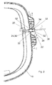
- the rear window 16 is provided with a trained in a conventional manner and therefore not shown in detail rear window heater, which is provided with a connection element which is designed as a contact tab 20 which, as FIG. 3 can be seen from a rear window inside, on which the rear window heating is formed along the profile of the rear window frame 18 is guided to a heating connection area 22.
- a connection element which is designed as a contact tab 20 which, as FIG. 3 can be seen from a rear window inside, on which the rear window heating is formed along the profile of the rear window frame 18 is guided to a heating connection area 22.
- the contact lug 20 made of a metal strip engages with a contact plug 24 which is formed on a supply line 26, which leads to a On-board network of the relevant motor vehicle leads.
- the contact plug 24 is thus attached to the contact tab 20
- a receptacle 28 is formed in the heating connection area 22, which corresponds to the cuboid shape of a housing 30 of the contact plug 24.
- the receptacle 28 is laterally bounded on each side by two guide webs 32 and in each case by a latching hook 34, which is arranged between the two guide webs 32 of the respective side.
- the guide webs 32 and the latching hooks 34 are in the mounting position on the side of the housing 30 of the contact plug 24.
- the latching hooks 34 each have a hook section 36 on the front side, which engages over the housing 30 of the contact plug 24 and thus holds it in position or in the receptacle 28 of the rear window frame 18 from above.
- a locking projection 38 is further formed on the rear window frame 18 as an additional locking means, which engages behind the rear window 16 facing away from the front side of the housing 30 of the contact plug 24.
- the housing 30 of the contact plug 24 in the region of its rear, that is, the rear window 16 facing away from a stop 40 which comes into abutment with one of the guide webs 32 in the mounted state and so the end position of Contact plug 24 during its assembly, that is defined at its connection to the contact tab 20.
Landscapes
- Engineering & Computer Science (AREA)
- Mechanical Engineering (AREA)
- Window Of Vehicle (AREA)
- Air-Conditioning For Vehicles (AREA)
- Body Structure For Vehicles (AREA)
Abstract
Description
- Die Erfindung betrifft ein Verdeck eines Cabriolet-Fahrzeugs mit den Merkmalen des Oberbegriffs des Patentanspruchs 1.
- Ein derartiges Verdeck ist aus der Praxis bekannt und dient als verstellbares Dach eines als Cabriolet ausgebildeten Kraftfahrzeuges. Das Verdeck umfasst hierzu einen Verdeckbezug, der mittels eines Verdeckgestänges zwischen einer einen Fahrzeuginsassenraum überspannenden Schließstellung und einer den Fahrzeuginsassenraum nach oben freigebenden Ablagestellung verstellbar ist. In einem heckseitigen Ausschnitt nimmt der Verdeckbezug eine Heckscheibe auf, die zur Anbindung an den Verdeckbezug mit einem Heckscheibenrahmen versehen ist. Die Heckscheibe kann eine Heckscheibenheizung aufweisen, die über ein Anschlusselement mit einer elektrischen Versorgungsleitung verbunden ist. Ein an der elektrischen Versorgungsleitung ausgebildetes Gegenelement zu dem Anschlusselement ist zur mechanischen Fixierung mittels Befestigungsmaterial, wie einen Kabelbinder, ein Klettband oder dergleichen, an dem Heckscheibenrahmen oder auch an einem dem Verdeckgestänge zugeordneten Heckscheibenrahmenlenker befestigt. Die Verwendung des Befestigungsmaterials erfordert eine aufwändige Montage und ist zudem mit zusätzlichen Kosten verbunden.
- Der Erfindung liegt die Aufgabe zugrunde, ein Verdeck der einleitend genannten Gattung zu schaffen, das eine gegenüber dem vorstehend beschriebenen Stand der Technik vereinfachte und kostengünstigere Anbindung der Heckscheibenheizung an eine Versorgungsleitung ermöglicht.
- Diese Aufgabe ist erfindungsgemäß durch das Verdeck mit den Merkmalen des Oberbegriffs des Patentanspruchs 1 gelöst.
- Erfindungsgemäß wird mithin ein Verdeck eines Cabriolet-Fahrzeugs vorgeschlagen, das einen Verdeckbezug umfasst, der mittels eines Verdeckgestänges zwischen einer einen Fahrzeuginsassenraum überspannenden Schließstellung und einer den Fahrzeuginsassenraum nach oben freigebenden Ablagestellung verstellbar ist. In einem heckseitigen Ausschnitt nimmt der Verdeckbezug eine Heckscheibe auf, die zur Anbindung an den Verdeckbezug mit einem Heckscheibenrahmen versehen ist und eine Heckscheibenheizung aufweist, die über ein Anschlusselement mit einer elektrischen Versorgungsleitung verbunden ist. Das Anschlusselement ist eine Kontaktlasche, die mit einem Kontaktstecker der elektrischen Versorgungsleitung in Eingriff steht, der in einer korrespondierenden Aufnahme des Heckscheibenrahmens verrastet ist.
- Vorgeschlagen wird gemäß der Erfindung also eine Steckverbindung zwischen dem eine Kontaktlasche darstellenden Anschlusselement und dem Kontaktstecker der elektrischen Versorgungsleitung. Zudem ist der Kontaktstecker dadurch fixiert, dass er direkt an dem Heckscheibenrahmen verrastet bzw. verklipst ist, und zwar in der eigens für den Kontaktstecker vorgesehenen Aufnahme des Heckscheibenrahmens. Es ist damit kein zusätzliches Befestigungsmaterial zum Fixieren des Kontaktsteckers und damit auch kein zusätzlicher Bauraum für selbiges erforderlich. Zudem stellt das Stecken und Verrasten des Kontaktsteckers einen einfachen Montageschritt dar. Durch entsprechende Gestaltung des Heckscheibenrahmens ist der Kontaktstecker auch prozesssicher und platzsparend in dem durch die Aufnahme definierten Bauraum verbaubar.
- Bei einer besonders montagefreundlichen Ausführungsform weist der Kontaktstecker vorzugsweise ein zumindest annähernd quaderförmig ausgebildetes Gehäuse auf, das von mindestens zwei Rasthaken des Heckscheibenrahmens in der Aufnahme gehalten ist. Damit kann auch die Geometrie der Rasthaken einfach gehalten werden.
- Bei einer zweckmäßigen Ausführungsform des Verdecks nach der Erfindung begrenzen die Rasthaken die Aufnahme und damit auch den Kontaktstecker seitlich, wobei sie das Gehäuse des Kontaktsteckers jeweils mit einem Hakenabschnitt übergreifen. Die Rasthaken können federnd ausgebildet sein. Damit kann der Kontaktstecker von oben zwischen den Hakenabschnitten hindurchgeführt werden, die bei Erreichen der Montagestellung über das Kontaktsteckergehäuse schnappen und den Kontaktstecker von oben in der Aufnahme halten.
- Um den Kontaktstecker bzw. dessen Gehäuse auch in einer dritten Raumrichtung sicher an dem Heckscheibenrahmen halten zu können, sind bei einer bevorzugten Ausführungsform des Verdecks nach der Erfindung Rastmittel vorgesehen, die das Gehäuse des Kontaktsteckers parallel zur Achse der Kontaktlasche an dem Heckscheibenrahmen in Position halten. Beispielsweise sind an dem Gehäuse des Kontaktsteckers seitlich Ausnehmungen ausgebildet, in die jeweils ein Rastzapfen oder dergleichen eingreift, der federnd an dem Heckscheibenrahmen ausgebildet ist. Das in die Ausnehmung des Gehäuses des Kontaktsteckers eingreifende Element kann auch einer der Rasthaken sein, der die Aufnahme seitlich begrenzt. Auch kann eine Rastnase vorgesehen sein, die das Gehäuse des Kontaktsteckers an dessen der Heckscheibe abgewandten Stirnseite hintergreift und stützt.
- Um eine Endposition des Kontaktsteckers bei der Montage an dem Heckscheibenrahmen zu definieren, weist das Gehäuse des Kontaktsteckers vorzugsweise einen Anschlag auf, der mit einem Gegenanschlag des Heckscheibenrahmens zusammenwirkt und eine Endlage des Kontaktsteckers gegenüber dem Heckscheibenrahmen bei der Montage definiert. Der Gegenanschlag ist beispielsweise von einem Führungssteg gebildet, der die Aufnahme seitlich begrenzt und dessen der Aufnahme zugewandte Führungsfläche mit einer Anlagefläche des auf der betreffenden Seite angeordneten Rasthakens fluchtet.
- Die Kontaktlasche erstreckt sich zweckmäßigerweise zumindest in ihrem mit dem Kontaktstecker in Eingriff stehenden Abschnitt zumindest annährend parallel zur Ebene der Heckscheibe. Damit kann ein einfaches Einschieben des Kontaktsteckers in die Aufnahme des Heckscheibenrahmens gewährleistet werden und der Kontaktstecker entlang einer Linie in die Aufnahme des Heckscheibenrahmens eingeschoben werden, die der Achse der Kontaktlasche entspricht.
- Um dem Heckscheibenrahmen eine den Anforderungen entsprechende, gegebenenfalls auch komplexe Geometrie verleihen zu können, ist dieser vorzugsweise als Kunststoffspritzgießteil ausgebildet.
- Weitere Vorteile und vorteilhafte Ausgestaltungen des Gegenstandes der Erfindung sind der Beschreibung, der Zeichnung und den Patentansprüchen entnehmbar.
- Ein Ausführungsbeispiel eines Verdecks nach der Erfindung ist in der Zeichnung schematisch vereinfacht dargestellt und wird in der nachfolgenden Beschreibung näher erläutert. Es zeigt:
- Figur 1
- eine perspektivische Ansicht auf ein Faltverdeck in dessen einen Fahrzeuginsassenraum überspannenden Schließstellung;
- Figur 2
- eine Draufsicht auf einen Heckscheibenrahmen nach
Figur 2 des Faltverdecks; - Figur 3
- einen Schnitt durch den Heckscheibenrahmen entlang der Linie D-D in
Figur 2 ; - Figur 4
- einen Schnitt durch den Heckscheibenrahmen nach
Figur 2 entlang der Linie C-C inFigur 2 ; und - Figur 5
- einen weiteren Schnitt durch den Heckscheibenrahmen nach
Figur 2 entlang der Linie B-B inFigur 2 . - In der Zeichnung ist ein Faltverdeck 10 dargestellt, das ein verstellbares Dach eines als Cabriolet ausgebildeten, im Übrigen nicht näher dargestellten Kraftfahrzeuges ist und hierzu zwischen einer in
Figur 1 dargestellten, einen Fahrzeuginsassenraum überspannenden Schließstellung und einer den Fahrzeuginsassenraum nach oben freigebenden Ablagestellung verstellbar ist, in der es von einem heckseitigen Verdeckablagekasten des Kraftfahrzeuges aufgenommen ist. Zum Verstellen weist das Faltverdeck ein nicht näher dargestelltes Verdeckgestänge auf, das über entsprechende Hauptlager im Bereich des heckseitigen Verdeckablagekastens des Kraftfahrzeuges gelagert ist. - Das Faltverdeck 10 umfasst einen Verdeckbezug 12 aus einem wasserdichten und witterungsbeständigen textilen Material, der mittels des Verdeckgestänges zum Überspannen des Fahrzeuginsassenraums aufspannbar ist. In einem heckseitigen Abschnitt weist der Verdeckbezug 12 einen Ausschnitt 14 auf, in dem eine Heckscheibe 16 angeordnet ist, die über einen in den
Figuren 2 bis 5 näher dargestellten Heckscheibenrahmen 18 an den Verdeckbezug 12 angebunden ist. - Die Heckscheibe 16 ist mit einer in üblicher Weise ausgebildeten und daher nicht näher dargestellten Heckscheibenheizung versehen, welche mit einem Anschlusselement versehen ist, das als Kontaktlasche 20 ausgebildet ist, welche, wie
Figur 3 zu entnehmen ist, von einer Heckscheibeninnenseite, an der die Heckscheibenheizung ausgebildet ist, entlang der Profilierung des Heckscheibenrahmens 18 zu einem Heizungsanschlussbereich 22 geführt ist. In dem Heizungsanschlussbereich 22, in dem sich die Achse der Kontaktlasche 20 zumindest weitgehend annähernd parallel zur Ebene der Heckscheibe 16 erstreckt, steht die aus einem Metallstreifen gefertigte Kontaktlasche 20 mit einem Kontaktstecker 24 in Eingriff, der an einer Versorgungsleitung 26 ausgebildet ist, welche zu einem Bordnetz des betreffenden Kraftfahrzeuges führt. Der Kontaktstecker 24 ist also auf die Kontaktlasche 20 aufgesteckt - An dem ein Kunststoffspritzgießteil darstellenden Heckscheibenrahmen 18 ist in dem Heizungsanschlussbereich 22 eine Aufnahme 28 ausgeformt, welche mit der quaderartigen Form eines Gehäuses 30 des Kontaktsteckers 24 korrespondiert.
- Bezogen auf die Längsachse des Kontaktsteckers 24 ist die Aufnahme 28 beidseits seitlich jeweils von zwei Führungsstegen 32 und jeweils von einem Rasthaken 34 begrenzt, der zwischen den beiden Führungsstegen 32 der jeweiligen Seite angeordnet ist. Die Führungsstege 32 und die Rasthaken 34 liegen in Montagestellung seitlich an dem Gehäuse 30 des Kontaktsteckers 24 an. Die Rasthaken 34 weisen stirnseitig jeweils einen Hakenabschnitt 36 auf, der das Gehäuse 30 des Kontaktsteckers 24 übergreift und diesen so von oben in Position bzw. in der Aufnahme 28 des Heckscheibenrahmens 18 hält.
- Um ein Lösen des Kontaktsteckers 24 in seiner axialen Richtung zu verhindern, ist an dem Heckscheibenrahmen 18 des Weiteren als zusätzliches Rastmittel ein Rastvorsprung 38 ausgebildet, der die der Heckscheibe 16 abgewandte Stirnseite des Gehäuses 30 des Kontaktsteckers 24 hintergreift.
- Zudem weist das Gehäuse 30 des Kontaktsteckers 24 im Bereich seiner hinteren, das heißt der Heckscheibe 16 abgewandten Stirnseite einen Anschlag 40 auf, der mit einem der Führungsstege 32 im montierten Zustand zur Anlage kommt und so die Endlage des Kontaktsteckers 24 bei seiner Montage, das heißt bei seiner Anbindung an die Kontaktlasche 20 definiert.
-
- 10
- Faltverdeck
- 12
- Verdeckbezug
- 14
- Ausschnitt
- 16
- Heckscheibe
- 18
- Heckscheibenrahmen
- 20
- Kontaktlasche
- 22
- Heizungsanschlussbereich
- 24
- Kontaktstecker
- 26
- Versorgungsleitung
- 28
- Aufnahme
- 30
- Gehäuse
- 32
- Führungsstege
- 34
- Rasthaken
- 36
- Hakenabschnitt
- 38
- Rastvorsprung
- 40
- Anschlag
Claims (7)
- Verdeck eines Cabriolet-Fahrzeugs, umfassend einen Verdeckbezug, der mittels eines Verdeckgestänges zwischen einer einen Fahrzeuginsassenraum überspannenden Schließstellung und einer den Fahrzeuginsassenraum nach oben freigebenden Ablagestellung verstellbar ist und in einem heckseitigen Ausschnitt eine Heckscheibe (16) aufnimmt, die zur Anbindung an den Verdeckbezug mit einem Heckscheibenrahmen (18) versehen ist und eine Heckscheibenheizung aufweist, die über ein Anschlusselement mit einer elektrischen Versorgungsleitung (26) verbunden ist, dadurch gekennzeichnet, dass das Anschlusselement eine Kontaktlasche (20) ist, die mit einem Kontaktstecker (24) der elektrischen Versorgungsleitung (26) in Eingriff steht, der in einer korrespondierenden Aufnahme (28) des Heckscheibenrahmens (18) verrastet ist.
- Verdeck nach Anspruch 1, dadurch gekennzeichnet, dass der Kontaktstecker (24) ein zumindest annährend quaderformig ausgebildetes Gehäuse (30) aufweist, das von mindestens zwei Rasthaken (34), die an dem Heckscheibenrahmen (18) ausgebildet sind, in der Aufnahme gehalten ist.
- Verdeck nach Anspruch 2, dadurch gekennzeichnet, dass die Rasthaken (34) die Aufnahme (28) seitlich begrenzen und das Gehäuse (30) des Kontaktsteckers (24) jeweils mit einem Hakenabschnitt (36) übergreifen.
- Verdeck nach einem der Ansprüche 1 bis 3, gekennzeichnet durch Rastmittel (38), die das Gehäuse (30) des Kontaktsteckers (24) parallel zur Achse der Kontaktlasche (20) an dem Heckscheibenrahmen (16) in Position halten.
- Verdeck nach einem der Ansprüche 1 bis 4, dadurch gekennzeichnet, dass das Gehäuse (30) des Kontaktsteckers (24) einen Anschlag (40) aufweist, der mit einem Gegenanschlag des Heckscheibenrahmens (16) zusammenwirkt und eine Endlage des Kontaktsteckers (24) gegenüber dem Heckscheibenrahmen (16) bei der Montage definiert.
- Verdeck nach einem der Ansprüche 1 bis 5, dadurch gekennzeichnet, dass sich die Kontaktlasche (20) zumindest in seinem mit dem Kontaktstecker (24) in Eingriff stehenden Abschnitt zumindest annähernd parallel zur Ebene der Heckscheibe (16) erstreckt.
- Verdeck nach einem der Ansprüche 1 bis 6, dadurch gekennzeichnet, dass der Heckscheibenrahmen (18) ein Kunststoffspritzgießteil ist.
Applications Claiming Priority (1)
| Application Number | Priority Date | Filing Date | Title |
|---|---|---|---|
| DE102012110906.0A DE102012110906B4 (de) | 2012-11-13 | 2012-11-13 | Cabriolet-Verdeck mit Heckscheibenheizung |
Publications (3)
| Publication Number | Publication Date |
|---|---|
| EP2731401A2 true EP2731401A2 (de) | 2014-05-14 |
| EP2731401A3 EP2731401A3 (de) | 2016-07-13 |
| EP2731401B1 EP2731401B1 (de) | 2017-08-09 |
Family
ID=49578156
Family Applications (1)
| Application Number | Title | Priority Date | Filing Date |
|---|---|---|---|
| EP13192494.6A Not-in-force EP2731401B1 (de) | 2012-11-13 | 2013-11-12 | Cabriolet-Verdeck mit Heckscheibenheizung |
Country Status (2)
| Country | Link |
|---|---|
| EP (1) | EP2731401B1 (de) |
| DE (1) | DE102012110906B4 (de) |
Family Cites Families (6)
| Publication number | Priority date | Publication date | Assignee | Title |
|---|---|---|---|---|
| DE2529619A1 (de) * | 1975-07-03 | 1977-01-20 | Daimler Benz Ag | Steckbarer elektrischer anschluss |
| JP4010467B2 (ja) * | 1997-05-12 | 2007-11-21 | マツダ株式会社 | コンバーチブル・トップ組立体、並びにその製造方法、及び装置 |
| DE102007003015A1 (de) * | 2007-01-20 | 2008-07-24 | Wilhelm Karmann Gmbh | Anordnung wenigstens eines Halteelements an einer Kunststoffscheibe |
| DE102007046320A1 (de) * | 2007-09-27 | 2009-04-02 | Robert Bosch Gmbh | Kontaktierungsanordnung und Kontaktierungsverfahren für Leiterbahnen von Heizungen und Antennen in Kraftfahrzeugscheiben |
| DE102010035696A1 (de) * | 2009-10-12 | 2011-04-14 | Carl Freudenberg Kg | Elektrisch leitende Verbindung und Verbundglasscheibe damit |
| DE102010049103A1 (de) * | 2010-10-21 | 2012-04-26 | Daimler Ag | Kontakteinrichtung zum Kontaktieren von Leitungsstrukturen in einem Glasbauteil eines Kraftfahrzeuges |
-
2012
- 2012-11-13 DE DE102012110906.0A patent/DE102012110906B4/de not_active Expired - Fee Related
-
2013
- 2013-11-12 EP EP13192494.6A patent/EP2731401B1/de not_active Not-in-force
Non-Patent Citations (1)
| Title |
|---|
| None |
Also Published As
| Publication number | Publication date |
|---|---|
| DE102012110906B4 (de) | 2017-02-09 |
| DE102012110906A1 (de) | 2014-05-15 |
| EP2731401B1 (de) | 2017-08-09 |
| EP2731401A3 (de) | 2016-07-13 |
Similar Documents
| Publication | Publication Date | Title |
|---|---|---|
| DE102005054186B4 (de) | Windabweiser im Kraftfahrzeugbereich | |
| EP2282917B1 (de) | Wischblatt sowie wischarm | |
| DE102009048212A1 (de) | Wischblatt | |
| DE102011001630A1 (de) | Baugruppe, Adapter und Stecker für eine Baugruppe sowie Scheibenwischersystem mit einer Baugruppe | |
| DE102013104902A1 (de) | Wischarm für eine Scheibenwischanlage eines Kraftfahrzeugs, Wischblatt und Wischeinrichtung | |
| DE102009041903B3 (de) | Mechanik für Schiebedächer | |
| DE102008052965A1 (de) | Vorrichtung zur Befestigung eines Formhimmels an einem Panorama-oder Schiebedach eines Fahrzeugs | |
| DE102019203686A1 (de) | Scheibenwischeranordnung mit einer separaten Anschlusseinheit zum Herstellen einer elektrischen Verbindung | |
| EP3331716B1 (de) | Windabweiser mit befestigungssystem für aufspannbares abweiserelement | |
| DE102019203715A1 (de) | Scheibenwischeranordnung mit einer Adaptereinheit zum Herstellen von fluidleitenden und elektrischen Verbindungen | |
| DE102013010883A1 (de) | Kraftfahrzeugverdeck | |
| DE102011011094A1 (de) | Blende für eine Antenne eines Kraftfahrzeugs und Dachanordnung | |
| EP2731401B1 (de) | Cabriolet-Verdeck mit Heckscheibenheizung | |
| DE102013208652A1 (de) | Befestigungselement zur Anbindung von Übertragungsmitteln an ein Hebelelement | |
| DE102009057022B4 (de) | Vorrichtung zum Führen von Reinigungsflüssigkeit | |
| WO2012079857A1 (de) | Wischblattvorrichtung | |
| EP2382104B1 (de) | Verdeck eines cabriolet-fahrzeugs mit wenigstens zwei dachsegmenten und einem innenhimmel | |
| EP2358554B1 (de) | Verdeck eines cabriolet-fahrzeugs mit wenigstens zwei dachsegmenten und einem innenhimmel | |
| DE112020003702B4 (de) | Sonnenblende für ein fahrzeug und verfahren zur montage | |
| DE102017108297A1 (de) | Verdeck mit Zentrierzapfen für Dachspitze | |
| DE102018132128A1 (de) | Windabweiseranordnung für ein Fahrzeugdach eines Fahrzeugs, Fahrzeugdach sowie Verfahren zur Montage einer Windabweiseranordnung | |
| DE102017213776A1 (de) | Anordnung für einen Fahrzeuginnenraum | |
| DE102021124555B4 (de) | Rolloanordnung mit Zugspriegel und Antriebskabeln | |
| DE102012205835A1 (de) | Wischblattvorrichtung | |
| DE10160461B4 (de) | Softtop-Fahrzeugverdeck mit einem Dichtungselement |
Legal Events
| Date | Code | Title | Description |
|---|---|---|---|
| PUAI | Public reference made under article 153(3) epc to a published international application that has entered the european phase |
Free format text: ORIGINAL CODE: 0009012 |
|
| 17P | Request for examination filed |
Effective date: 20131112 |
|
| AK | Designated contracting states |
Kind code of ref document: A2 Designated state(s): AL AT BE BG CH CY CZ DE DK EE ES FI FR GB GR HR HU IE IS IT LI LT LU LV MC MK MT NL NO PL PT RO RS SE SI SK SM TR |
|
| AX | Request for extension of the european patent |
Extension state: BA ME |
|
| PUAL | Search report despatched |
Free format text: ORIGINAL CODE: 0009013 |
|
| AK | Designated contracting states |
Kind code of ref document: A3 Designated state(s): AL AT BE BG CH CY CZ DE DK EE ES FI FR GB GR HR HU IE IS IT LI LT LU LV MC MK MT NL NO PL PT RO RS SE SI SK SM TR |
|
| AX | Request for extension of the european patent |
Extension state: BA ME |
|
| RIC1 | Information provided on ipc code assigned before grant |
Ipc: H05B 3/84 20060101ALI20160608BHEP Ipc: B60J 1/18 20060101ALI20160608BHEP Ipc: H01R 13/639 20060101ALI20160608BHEP Ipc: H05B 3/34 20060101AFI20160608BHEP |
|
| STAA | Information on the status of an ep patent application or granted ep patent |
Free format text: STATUS: REQUEST FOR EXAMINATION WAS MADE |
|
| R17P | Request for examination filed (corrected) |
Effective date: 20170105 |
|
| RBV | Designated contracting states (corrected) |
Designated state(s): AL AT BE BG CH CY CZ DE DK EE ES FI FR GB GR HR HU IE IS IT LI LT LU LV MC MK MT NL NO PL PT RO RS SE SI SK SM TR |
|
| GRAP | Despatch of communication of intention to grant a patent |
Free format text: ORIGINAL CODE: EPIDOSNIGR1 |
|
| STAA | Information on the status of an ep patent application or granted ep patent |
Free format text: STATUS: GRANT OF PATENT IS INTENDED |
|
| INTG | Intention to grant announced |
Effective date: 20170322 |
|
| GRAS | Grant fee paid |
Free format text: ORIGINAL CODE: EPIDOSNIGR3 |
|
| GRAA | (expected) grant |
Free format text: ORIGINAL CODE: 0009210 |
|
| STAA | Information on the status of an ep patent application or granted ep patent |
Free format text: STATUS: THE PATENT HAS BEEN GRANTED |
|
| AK | Designated contracting states |
Kind code of ref document: B1 Designated state(s): AL AT BE BG CH CY CZ DE DK EE ES FI FR GB GR HR HU IE IS IT LI LT LU LV MC MK MT NL NO PL PT RO RS SE SI SK SM TR |
|
| REG | Reference to a national code |
Ref country code: GB Ref legal event code: FG4D Free format text: NOT ENGLISH |
|
| REG | Reference to a national code |
Ref country code: CH Ref legal event code: EP Ref country code: AT Ref legal event code: REF Ref document number: 918126 Country of ref document: AT Kind code of ref document: T Effective date: 20170815 |
|
| REG | Reference to a national code |
Ref country code: IE Ref legal event code: FG4D Free format text: LANGUAGE OF EP DOCUMENT: GERMAN |
|
| REG | Reference to a national code |
Ref country code: DE Ref legal event code: R096 Ref document number: 502013007993 Country of ref document: DE |
|
| REG | Reference to a national code |
Ref country code: NL Ref legal event code: MP Effective date: 20170809 |
|
| REG | Reference to a national code |
Ref country code: LT Ref legal event code: MG4D |
|
| PG25 | Lapsed in a contracting state [announced via postgrant information from national office to epo] |
Ref country code: HR Free format text: LAPSE BECAUSE OF FAILURE TO SUBMIT A TRANSLATION OF THE DESCRIPTION OR TO PAY THE FEE WITHIN THE PRESCRIBED TIME-LIMIT Effective date: 20170809 Ref country code: SE Free format text: LAPSE BECAUSE OF FAILURE TO SUBMIT A TRANSLATION OF THE DESCRIPTION OR TO PAY THE FEE WITHIN THE PRESCRIBED TIME-LIMIT Effective date: 20170809 Ref country code: NL Free format text: LAPSE BECAUSE OF FAILURE TO SUBMIT A TRANSLATION OF THE DESCRIPTION OR TO PAY THE FEE WITHIN THE PRESCRIBED TIME-LIMIT Effective date: 20170809 Ref country code: LT Free format text: LAPSE BECAUSE OF FAILURE TO SUBMIT A TRANSLATION OF THE DESCRIPTION OR TO PAY THE FEE WITHIN THE PRESCRIBED TIME-LIMIT Effective date: 20170809 Ref country code: NO Free format text: LAPSE BECAUSE OF FAILURE TO SUBMIT A TRANSLATION OF THE DESCRIPTION OR TO PAY THE FEE WITHIN THE PRESCRIBED TIME-LIMIT Effective date: 20171109 Ref country code: FI Free format text: LAPSE BECAUSE OF FAILURE TO SUBMIT A TRANSLATION OF THE DESCRIPTION OR TO PAY THE FEE WITHIN THE PRESCRIBED TIME-LIMIT Effective date: 20170809 |
|
| PG25 | Lapsed in a contracting state [announced via postgrant information from national office to epo] |
Ref country code: IS Free format text: LAPSE BECAUSE OF FAILURE TO SUBMIT A TRANSLATION OF THE DESCRIPTION OR TO PAY THE FEE WITHIN THE PRESCRIBED TIME-LIMIT Effective date: 20171209 Ref country code: BG Free format text: LAPSE BECAUSE OF FAILURE TO SUBMIT A TRANSLATION OF THE DESCRIPTION OR TO PAY THE FEE WITHIN THE PRESCRIBED TIME-LIMIT Effective date: 20171109 Ref country code: ES Free format text: LAPSE BECAUSE OF FAILURE TO SUBMIT A TRANSLATION OF THE DESCRIPTION OR TO PAY THE FEE WITHIN THE PRESCRIBED TIME-LIMIT Effective date: 20170809 Ref country code: PL Free format text: LAPSE BECAUSE OF FAILURE TO SUBMIT A TRANSLATION OF THE DESCRIPTION OR TO PAY THE FEE WITHIN THE PRESCRIBED TIME-LIMIT Effective date: 20170809 Ref country code: LV Free format text: LAPSE BECAUSE OF FAILURE TO SUBMIT A TRANSLATION OF THE DESCRIPTION OR TO PAY THE FEE WITHIN THE PRESCRIBED TIME-LIMIT Effective date: 20170809 Ref country code: GR Free format text: LAPSE BECAUSE OF FAILURE TO SUBMIT A TRANSLATION OF THE DESCRIPTION OR TO PAY THE FEE WITHIN THE PRESCRIBED TIME-LIMIT Effective date: 20171110 Ref country code: RS Free format text: LAPSE BECAUSE OF FAILURE TO SUBMIT A TRANSLATION OF THE DESCRIPTION OR TO PAY THE FEE WITHIN THE PRESCRIBED TIME-LIMIT Effective date: 20170809 |
|
| PG25 | Lapsed in a contracting state [announced via postgrant information from national office to epo] |
Ref country code: DK Free format text: LAPSE BECAUSE OF FAILURE TO SUBMIT A TRANSLATION OF THE DESCRIPTION OR TO PAY THE FEE WITHIN THE PRESCRIBED TIME-LIMIT Effective date: 20170809 Ref country code: CZ Free format text: LAPSE BECAUSE OF FAILURE TO SUBMIT A TRANSLATION OF THE DESCRIPTION OR TO PAY THE FEE WITHIN THE PRESCRIBED TIME-LIMIT Effective date: 20170809 Ref country code: RO Free format text: LAPSE BECAUSE OF FAILURE TO SUBMIT A TRANSLATION OF THE DESCRIPTION OR TO PAY THE FEE WITHIN THE PRESCRIBED TIME-LIMIT Effective date: 20170809 |
|
| REG | Reference to a national code |
Ref country code: DE Ref legal event code: R097 Ref document number: 502013007993 Country of ref document: DE |
|
| PG25 | Lapsed in a contracting state [announced via postgrant information from national office to epo] |
Ref country code: SK Free format text: LAPSE BECAUSE OF FAILURE TO SUBMIT A TRANSLATION OF THE DESCRIPTION OR TO PAY THE FEE WITHIN THE PRESCRIBED TIME-LIMIT Effective date: 20170809 Ref country code: EE Free format text: LAPSE BECAUSE OF FAILURE TO SUBMIT A TRANSLATION OF THE DESCRIPTION OR TO PAY THE FEE WITHIN THE PRESCRIBED TIME-LIMIT Effective date: 20170809 Ref country code: SM Free format text: LAPSE BECAUSE OF FAILURE TO SUBMIT A TRANSLATION OF THE DESCRIPTION OR TO PAY THE FEE WITHIN THE PRESCRIBED TIME-LIMIT Effective date: 20170809 Ref country code: IT Free format text: LAPSE BECAUSE OF FAILURE TO SUBMIT A TRANSLATION OF THE DESCRIPTION OR TO PAY THE FEE WITHIN THE PRESCRIBED TIME-LIMIT Effective date: 20170809 |
|
| PLBE | No opposition filed within time limit |
Free format text: ORIGINAL CODE: 0009261 |
|
| STAA | Information on the status of an ep patent application or granted ep patent |
Free format text: STATUS: NO OPPOSITION FILED WITHIN TIME LIMIT |
|
| PG25 | Lapsed in a contracting state [announced via postgrant information from national office to epo] |
Ref country code: MC Free format text: LAPSE BECAUSE OF FAILURE TO SUBMIT A TRANSLATION OF THE DESCRIPTION OR TO PAY THE FEE WITHIN THE PRESCRIBED TIME-LIMIT Effective date: 20170809 |
|
| 26N | No opposition filed |
Effective date: 20180511 |
|
| PG25 | Lapsed in a contracting state [announced via postgrant information from national office to epo] |
Ref country code: LI Free format text: LAPSE BECAUSE OF NON-PAYMENT OF DUE FEES Effective date: 20171130 Ref country code: CH Free format text: LAPSE BECAUSE OF NON-PAYMENT OF DUE FEES Effective date: 20171130 |
|
| PG25 | Lapsed in a contracting state [announced via postgrant information from national office to epo] |
Ref country code: SI Free format text: LAPSE BECAUSE OF FAILURE TO SUBMIT A TRANSLATION OF THE DESCRIPTION OR TO PAY THE FEE WITHIN THE PRESCRIBED TIME-LIMIT Effective date: 20170809 Ref country code: LU Free format text: LAPSE BECAUSE OF NON-PAYMENT OF DUE FEES Effective date: 20171112 |
|
| REG | Reference to a national code |
Ref country code: FR Ref legal event code: ST Effective date: 20180731 Ref country code: BE Ref legal event code: MM Effective date: 20171130 |
|
| REG | Reference to a national code |
Ref country code: IE Ref legal event code: MM4A |
|
| PG25 | Lapsed in a contracting state [announced via postgrant information from national office to epo] |
Ref country code: MT Free format text: LAPSE BECAUSE OF FAILURE TO SUBMIT A TRANSLATION OF THE DESCRIPTION OR TO PAY THE FEE WITHIN THE PRESCRIBED TIME-LIMIT Effective date: 20170809 |
|
| PG25 | Lapsed in a contracting state [announced via postgrant information from national office to epo] |
Ref country code: IE Free format text: LAPSE BECAUSE OF NON-PAYMENT OF DUE FEES Effective date: 20171112 Ref country code: FR Free format text: LAPSE BECAUSE OF NON-PAYMENT OF DUE FEES Effective date: 20171130 |
|
| PG25 | Lapsed in a contracting state [announced via postgrant information from national office to epo] |
Ref country code: BE Free format text: LAPSE BECAUSE OF NON-PAYMENT OF DUE FEES Effective date: 20171130 |
|
| PG25 | Lapsed in a contracting state [announced via postgrant information from national office to epo] |
Ref country code: HU Free format text: LAPSE BECAUSE OF FAILURE TO SUBMIT A TRANSLATION OF THE DESCRIPTION OR TO PAY THE FEE WITHIN THE PRESCRIBED TIME-LIMIT; INVALID AB INITIO Effective date: 20131112 |
|
| PG25 | Lapsed in a contracting state [announced via postgrant information from national office to epo] |
Ref country code: CY Free format text: LAPSE BECAUSE OF NON-PAYMENT OF DUE FEES Effective date: 20170809 |
|
| PG25 | Lapsed in a contracting state [announced via postgrant information from national office to epo] |
Ref country code: MK Free format text: LAPSE BECAUSE OF FAILURE TO SUBMIT A TRANSLATION OF THE DESCRIPTION OR TO PAY THE FEE WITHIN THE PRESCRIBED TIME-LIMIT Effective date: 20170809 |
|
| REG | Reference to a national code |
Ref country code: AT Ref legal event code: MM01 Ref document number: 918126 Country of ref document: AT Kind code of ref document: T Effective date: 20181112 |
|
| PG25 | Lapsed in a contracting state [announced via postgrant information from national office to epo] |
Ref country code: AT Free format text: LAPSE BECAUSE OF NON-PAYMENT OF DUE FEES Effective date: 20181112 |
|
| PG25 | Lapsed in a contracting state [announced via postgrant information from national office to epo] |
Ref country code: TR Free format text: LAPSE BECAUSE OF FAILURE TO SUBMIT A TRANSLATION OF THE DESCRIPTION OR TO PAY THE FEE WITHIN THE PRESCRIBED TIME-LIMIT Effective date: 20170809 |
|
| PG25 | Lapsed in a contracting state [announced via postgrant information from national office to epo] |
Ref country code: PT Free format text: LAPSE BECAUSE OF FAILURE TO SUBMIT A TRANSLATION OF THE DESCRIPTION OR TO PAY THE FEE WITHIN THE PRESCRIBED TIME-LIMIT Effective date: 20170809 |
|
| PG25 | Lapsed in a contracting state [announced via postgrant information from national office to epo] |
Ref country code: AL Free format text: LAPSE BECAUSE OF FAILURE TO SUBMIT A TRANSLATION OF THE DESCRIPTION OR TO PAY THE FEE WITHIN THE PRESCRIBED TIME-LIMIT Effective date: 20170809 |
|
| PGFP | Annual fee paid to national office [announced via postgrant information from national office to epo] |
Ref country code: GB Payment date: 20221123 Year of fee payment: 10 Ref country code: DE Payment date: 20221121 Year of fee payment: 10 |
|
| REG | Reference to a national code |
Ref country code: DE Ref legal event code: R119 Ref document number: 502013007993 Country of ref document: DE |
|
| GBPC | Gb: european patent ceased through non-payment of renewal fee |
Effective date: 20231112 |