EP2730863A1 - Dispositif de réfrigération et de climatisation et procédé pour commander le dispositif de réfrigération et de climatisation - Google Patents
Dispositif de réfrigération et de climatisation et procédé pour commander le dispositif de réfrigération et de climatisation Download PDFInfo
- Publication number
- EP2730863A1 EP2730863A1 EP11868973.6A EP11868973A EP2730863A1 EP 2730863 A1 EP2730863 A1 EP 2730863A1 EP 11868973 A EP11868973 A EP 11868973A EP 2730863 A1 EP2730863 A1 EP 2730863A1
- Authority
- EP
- European Patent Office
- Prior art keywords
- refrigerant
- compressor
- detection means
- composition
- refrigerating
- Prior art date
- Legal status (The legal status is an assumption and is not a legal conclusion. Google has not performed a legal analysis and makes no representation as to the accuracy of the status listed.)
- Granted
Links
- 238000004378 air conditioning Methods 0.000 title claims abstract description 103
- 238000005057 refrigeration Methods 0.000 title claims abstract description 36
- 238000000034 method Methods 0.000 title claims description 11
- 239000003507 refrigerant Substances 0.000 claims abstract description 416
- 238000001514 detection method Methods 0.000 claims abstract description 275
- 239000000203 mixture Substances 0.000 claims abstract description 248
- 230000000704 physical effect Effects 0.000 claims description 8
- 230000001419 dependent effect Effects 0.000 claims description 3
- 238000012545 processing Methods 0.000 description 31
- 238000007906 compression Methods 0.000 description 26
- 230000007246 mechanism Effects 0.000 description 25
- 239000007788 liquid Substances 0.000 description 23
- 230000008859 change Effects 0.000 description 21
- 238000011156 evaluation Methods 0.000 description 16
- 239000012071 phase Substances 0.000 description 9
- 238000005516 engineering process Methods 0.000 description 8
- 238000004088 simulation Methods 0.000 description 8
- 230000006835 compression Effects 0.000 description 6
- 230000003247 decreasing effect Effects 0.000 description 5
- 238000010438 heat treatment Methods 0.000 description 5
- 239000007791 liquid phase Substances 0.000 description 5
- 230000009471 action Effects 0.000 description 4
- 230000007423 decrease Effects 0.000 description 4
- 238000011161 development Methods 0.000 description 4
- 238000010586 diagram Methods 0.000 description 4
- 238000004364 calculation method Methods 0.000 description 3
- 238000001816 cooling Methods 0.000 description 3
- 230000008569 process Effects 0.000 description 3
- 230000009467 reduction Effects 0.000 description 3
- 230000000694 effects Effects 0.000 description 2
- 238000009434 installation Methods 0.000 description 2
- 230000035945 sensitivity Effects 0.000 description 2
- 230000001052 transient effect Effects 0.000 description 2
- 238000009835 boiling Methods 0.000 description 1
- 230000003292 diminished effect Effects 0.000 description 1
- 238000001704 evaporation Methods 0.000 description 1
- 238000002474 experimental method Methods 0.000 description 1
- -1 for example Substances 0.000 description 1
- 230000006872 improvement Effects 0.000 description 1
- 230000004044 response Effects 0.000 description 1
- 230000000087 stabilizing effect Effects 0.000 description 1
- 238000012360 testing method Methods 0.000 description 1
- 238000010792 warming Methods 0.000 description 1
Images

Classifications
-
- F—MECHANICAL ENGINEERING; LIGHTING; HEATING; WEAPONS; BLASTING
- F25—REFRIGERATION OR COOLING; COMBINED HEATING AND REFRIGERATION SYSTEMS; HEAT PUMP SYSTEMS; MANUFACTURE OR STORAGE OF ICE; LIQUEFACTION SOLIDIFICATION OF GASES
- F25B—REFRIGERATION MACHINES, PLANTS OR SYSTEMS; COMBINED HEATING AND REFRIGERATION SYSTEMS; HEAT PUMP SYSTEMS
- F25B49/00—Arrangement or mounting of control or safety devices
- F25B49/02—Arrangement or mounting of control or safety devices for compression type machines, plants or systems
-
- F—MECHANICAL ENGINEERING; LIGHTING; HEATING; WEAPONS; BLASTING
- F25—REFRIGERATION OR COOLING; COMBINED HEATING AND REFRIGERATION SYSTEMS; HEAT PUMP SYSTEMS; MANUFACTURE OR STORAGE OF ICE; LIQUEFACTION SOLIDIFICATION OF GASES
- F25B—REFRIGERATION MACHINES, PLANTS OR SYSTEMS; COMBINED HEATING AND REFRIGERATION SYSTEMS; HEAT PUMP SYSTEMS
- F25B49/00—Arrangement or mounting of control or safety devices
-
- F—MECHANICAL ENGINEERING; LIGHTING; HEATING; WEAPONS; BLASTING
- F25—REFRIGERATION OR COOLING; COMBINED HEATING AND REFRIGERATION SYSTEMS; HEAT PUMP SYSTEMS; MANUFACTURE OR STORAGE OF ICE; LIQUEFACTION SOLIDIFICATION OF GASES
- F25B—REFRIGERATION MACHINES, PLANTS OR SYSTEMS; COMBINED HEATING AND REFRIGERATION SYSTEMS; HEAT PUMP SYSTEMS
- F25B13/00—Compression machines, plants or systems, with reversible cycle
-
- F—MECHANICAL ENGINEERING; LIGHTING; HEATING; WEAPONS; BLASTING
- F25—REFRIGERATION OR COOLING; COMBINED HEATING AND REFRIGERATION SYSTEMS; HEAT PUMP SYSTEMS; MANUFACTURE OR STORAGE OF ICE; LIQUEFACTION SOLIDIFICATION OF GASES
- F25B—REFRIGERATION MACHINES, PLANTS OR SYSTEMS; COMBINED HEATING AND REFRIGERATION SYSTEMS; HEAT PUMP SYSTEMS
- F25B2700/00—Sensing or detecting of parameters; Sensors therefor
- F25B2700/19—Pressures
- F25B2700/193—Pressures of the compressor
- F25B2700/1931—Discharge pressures
-
- F—MECHANICAL ENGINEERING; LIGHTING; HEATING; WEAPONS; BLASTING
- F25—REFRIGERATION OR COOLING; COMBINED HEATING AND REFRIGERATION SYSTEMS; HEAT PUMP SYSTEMS; MANUFACTURE OR STORAGE OF ICE; LIQUEFACTION SOLIDIFICATION OF GASES
- F25B—REFRIGERATION MACHINES, PLANTS OR SYSTEMS; COMBINED HEATING AND REFRIGERATION SYSTEMS; HEAT PUMP SYSTEMS
- F25B2700/00—Sensing or detecting of parameters; Sensors therefor
- F25B2700/19—Pressures
- F25B2700/193—Pressures of the compressor
- F25B2700/1933—Suction pressures
-
- F—MECHANICAL ENGINEERING; LIGHTING; HEATING; WEAPONS; BLASTING
- F25—REFRIGERATION OR COOLING; COMBINED HEATING AND REFRIGERATION SYSTEMS; HEAT PUMP SYSTEMS; MANUFACTURE OR STORAGE OF ICE; LIQUEFACTION SOLIDIFICATION OF GASES
- F25B—REFRIGERATION MACHINES, PLANTS OR SYSTEMS; COMBINED HEATING AND REFRIGERATION SYSTEMS; HEAT PUMP SYSTEMS
- F25B2700/00—Sensing or detecting of parameters; Sensors therefor
- F25B2700/21—Temperatures
- F25B2700/2115—Temperatures of a compressor or the drive means therefor
- F25B2700/21151—Temperatures of a compressor or the drive means therefor at the suction side of the compressor
-
- F—MECHANICAL ENGINEERING; LIGHTING; HEATING; WEAPONS; BLASTING
- F25—REFRIGERATION OR COOLING; COMBINED HEATING AND REFRIGERATION SYSTEMS; HEAT PUMP SYSTEMS; MANUFACTURE OR STORAGE OF ICE; LIQUEFACTION SOLIDIFICATION OF GASES
- F25B—REFRIGERATION MACHINES, PLANTS OR SYSTEMS; COMBINED HEATING AND REFRIGERATION SYSTEMS; HEAT PUMP SYSTEMS
- F25B2700/00—Sensing or detecting of parameters; Sensors therefor
- F25B2700/21—Temperatures
- F25B2700/2115—Temperatures of a compressor or the drive means therefor
- F25B2700/21152—Temperatures of a compressor or the drive means therefor at the discharge side of the compressor
Definitions
- the present invention relates to a refrigerating and air-conditioning apparatus that uses a non-azeotropic refrigerant mixture as a refrigerant, and particularly relates to a refrigerating and air-conditioning apparatus that is modified to improve accuracy of detecting the composition of the refrigerant.
- a refrigerating and air-conditioning apparatus that uses a non-azeotropic refrigerant mixture
- the composition of the circulating refrigerant may change.
- a change in the refrigerant composition becomes noticeable.
- changes in the condensing temperature or the evaporating temperature may occur even there is no change in the pressure.
- an improper refrigerant saturation temperature at a heat exchanger hinders the refrigerant from being readily condensed and liquefied or evaporated and gasified at the heat exchanger, and the heat exchange efficiency may be reduced.
- a refrigerating and air-conditioning apparatus including a refrigerant storage container (receiver) at a high-pressure side has a smaller fluctuation range of the composition of a circulating refrigerant than that of a refrigerating and air-conditioning apparatus including a refrigerant storage container (accumulator) at a low-pressure side.
- the fluctuation range of the refrigerant composition is increased regardless of whether the refrigerant storage container is at the low-pressure side or the high-pressure side. In other words, it is possible to detect refrigerant leak by detecting a fluctuation of the refrigerant composition.
- various refrigerating and air-conditioning apparatuses including means for detecting a refrigerant composition in order to suppress reduction in heat exchange efficiency, to avoid compressor damage, to suppress generation of refrigerant sound, to suppress an unstable phenomenon, and to detect refrigerant leak, have been proposed.
- a refrigerating and air-conditioning apparatus which includes a bypass connected so as to bypass a compressor and in which a double pipe heat exchanger and a capillary tube are connected to the bypass (e.g., see Patent Literature 1).
- a bypass connected so as to bypass a compressor and in which a double pipe heat exchanger and a capillary tube are connected to the bypass.
- Patent Literature 1 the temperature at the refrigerant inflow side of the capillary tube, the temperature at the refrigerant outflow side of the capillary tube, and the pressure at the refrigerant outflow side of the capillary tube are detected, and a refrigerant composition is calculated on the basis of these detection results.
- a refrigerating and air-conditioning apparatus which detects an excess refrigerant amount within an accumulator and calculates a refrigerant composition (e.g., see Patent Literature 2).
- a refrigerant composition is calculated on the basis of a correlation between information such as the number of operating indoor units and the outside air temperature and a previously obtained refrigerant composition, an excess refrigerant amount within the accumulator is detected, and the calculated refrigerant composition is corrected, whereby the composition of a circulating refrigerant is calculated.
- Patent Literature 1 is configured to detect a composition on the basis of states before and after an expansion process at the capillary tube. For example, when a plurality of expansion processes are present in parallel in a refrigeration cycle of the refrigerating and air-conditioning apparatus, the detection accuracy of a refrigerant composition to be detected may be decreased.
- Patent Literature 1 since the bypass is provided, an amount of the refrigerant circulating through the refrigeration cycle is reduced. Thus, the capability exerted by the refrigerating and air-conditioning apparatus is diminished, and the operation reliability of the refrigerating and air-conditioning apparatus may be decreased.
- Patent Literature 2 it is necessary to previously grasp a refrigerant composition from an operating state of the refrigerating and air-conditioning apparatus, and a considerable amount of evaluation work or simulation is required for each refrigerating and air-conditioning apparatus. Thus, the load and the cost of development are increased.
- a refrigerating and air-conditioning apparatus intends to provide a refrigerating and air-conditioning apparatus that has improved accuracy of detecting the composition of a circulating refrigerant and has improved operation reliability during operation while suppressing a cost increase.
- a refrigerating and air-conditioning apparatus includes a compressor, a condenser, an expansion device, and an evaporator, has a refrigeration cycle configured by these components being connected by a refrigerant pipe, and uses a non-azeotropic refrigerant mixture as a refrigerant circulating through the refrigeration cycle.
- the refrigerating and air-conditioning apparatus includes: operating state detection means for detecting an operating state of the compressor; output detection means for detecting an output of the compressor; and composition detection means for calculating a correlation between the operating state, the output, and a refrigerant composition and retaining data indicating the correlation.
- the composition detection means calculates a composition of the refrigerant circulating through the refrigeration cycle on the basis of a detection result of the operating state detection means, a detection result of the output detection means, and the data indicating the correlation.
- the composition detection means calculates the composition of the refrigerant circulating through the refrigeration cycle, on the basis of the detection result of the operating state detection means, the detection result of the output detection means, and the data indicating the correlation.
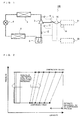
- Fig. 1 shows an example of a refrigerant circuit configuration of a refrigerating and air-conditioning apparatus 100 according to Embodiment 1 of the present invention.
- the refrigerating and air-conditioning apparatus 100 according to Embodiment 1 uses a non-azeotropic refrigerant mixture as a refrigerant, and performs control of various devices such as an opening degree of an expansion device (corresponding to a pressure reducing mechanism 4 described later) by detecting the refrigerant composition of the refrigerant.
- the refrigerating and air-conditioning apparatus 100 according to Embodiment 1 is modified to improve accuracy of detecting the composition of the refrigerant.
- a composition refers to the composition of a refrigerant circulating through a refrigeration cycle, and is not the composition of a refrigerant to be charged and the composition of a refrigerant present within a component of the refrigeration cycle.
- the refrigerating and air-conditioning apparatus 100 includes a compressor 2 which compresses the refrigerant, a condenser 3 which condenses and liquefies the refrigerant, the pressure reducing mechanism 4 which reduces the pressure of the refrigerant to expand the refrigerant, an evaporator 5 which evaporates and gasifies the refrigerant, and an accumulator 6 which stores an excess refrigerant, and has a refrigeration cycle configured by these components being connected by a refrigerant pipe.
- the refrigerating and air-conditioning apparatus 100 uses the non-azeotropic refrigerant mixture as a refrigerant circulating through the refrigeration cycle.
- Embodiment 1 as the non-azeotropic refrigerant mixture, R32 (a charged composition of R32 is 54 wt%) is used as a low-boiling-point refrigerant, and HFO1234yf (the charged composition thereof is 46 wt%) is used as a high-boiling-point refrigerant. It should be noted that in the case of this charged refrigerant composition, the global warming potential (GWP) of the non-azeotropic refrigerant mixture is 300.
- GWP global warming potential
- the refrigerating and air-conditioning apparatus 100 includes various devices for detecting the composition of the non-azeotropic refrigerant mixture.
- the refrigerating and air-conditioning apparatus 100 includes suction-side pressure detection means 11 which detects the pressure of the refrigerant sucked into the compressor 2, suction-side temperature detection means 12 which detects the temperature of the refrigerant sucked into the compressor 2, discharge-side pressure detection means 13 which detects the pressure of the refrigerant discharged from the compressor 2, rotation speed detection means 14 which detects the rotation speed of the compressor 2, and output detection means 15 which detects an output of the compressor 2.
- the refrigerating and air-conditioning apparatus 100 includes composition detection means 20 which detects a refrigerant composition on the basis of detection results of these detection means 11 to 15, and a controller 21 which integrally controls the rotation speed of the compressor 2 and various devices.
- the compressor 2 sucks the refrigerant, compresses the refrigerant into a high-temperature and high-pressure state, and discharges the refrigerant.
- the compressor 2 is connected at a discharge side thereof to the condenser 3 and connected at a suction side thereof to the accumulator 6.
- the compressor 2 may be, for example, a capacity-controllable inverter compressor or the like.
- the condenser 3 condenses and liquefies the high-temperature and high-pressure refrigerant supplied from the compressor 2.
- the condenser 3 is connected at one end thereof to the compressor 2 and connected at another end thereof to the pressure reducing mechanism 4. It should be noted that the condenser 3 is equipped with a fan (not shown) and prompts heat exchange between the refrigerant and air supplied from the fan. The air that is heat-exchanged with the refrigerant is blown out to, for example, the outside of a room or the like by the action of the fan.
- the pressure reducing mechanism 4 reduces the pressure of a liquid refrigerant flowing thereinto from the condenser 3, to expand the liquid refrigerant.
- the pressure reducing mechanism 4 may be a mechanism whose opening degree is variably controllable, such as an electronic expansion valve.
- the pressure reducing mechanism 4 is connected at one end thereof to the condenser 3 and connected at another end thereof to the evaporator 5.
- the evaporator 5 evaporates and gasifies a gas-liquid two-phase refrigerant flowing thereinto from the pressure reducing mechanism 4.
- the evaporator 5 is connected at one end thereof to the pressure reducing mechanism 4 and connected at another end thereof to the accumulator 6.
- the evaporator 5 is equipped with a fan (not shown) and prompts heat exchange between the refrigerant and air supplied from the fan.
- the air that is heat-exchanged with the refrigerant is blown out to an air-conditioned space (e.g., the inside of a room, a storehouse, etc.) by the action of the fan.
- the accumulator 6 stores an excess refrigerant caused by a change of a transient operation (e.g., a change of the output of the compressor 2).
- the accumulator 6 is connected at one end thereof to the evaporator 5 and connected at another end thereof to the suction side of the compressor 2.
- the suction-side pressure detection means 11 detects the pressure of the refrigerant sucked into the compressor 2 (low-pressure-side refrigerant pressure), and is, for example, a pressure sensor or the like. In other words, the suction-side pressure detection means 11 detects the pressure of the refrigerant whose pressure is reduced by the action of the pressure reducing mechanism 4, in order to detect a refrigerant composition. In addition, the suction-side pressure detection means 11 is connected to the composition detection means 20.
- Fig. 1 illustrates an example where the suction-side pressure detection means 11 is installed on a refrigerant pipe near an inlet of the compressor 2, but the present invention is not limited thereto.
- the suction-side pressure detection means 11 may be installed on a refrigerant pipe (including the evaporator 5 and the accumulator 6) from a refrigerant outlet of the pressure reducing mechanism 4 to the inlet of the compressor 2.
- a pressure detection sensor (not shown) for controlling the rotation speed of the fan of the condenser 3, the opening degree of the pressure reducing mechanism 4, and the like, into one unit, and thus it is possible to reduce the cost.
- the suction-side temperature detection means 12 detects the temperature of the refrigerant sucked into the compressor 2 (low-pressure-side refrigerant temperature), and is, for example, a temperature sensor or the like. In addition, the suction-side temperature detection means 12 is connected to the composition detection means 20.
- Fig. 1 illustrates an example where the suction-side temperature detection means 12 is installed on a refrigerant pipe connecting the accumulator 6 to the compressor 2, but the present invention is not limited thereto. Specifically, the suction-side temperature detection means 12 may be installed inside the compressor 2 and at a position before the refrigerant is compressed (at a position before entering a compression process).
- the suction-side temperature detection means 12 when the suction-side temperature detection means 12 is provided on the pipe surface, the suction-side temperature detection means 12 is susceptible to the ambient environment (disturbance). For example, when one type of compressors are installed in a plurality of different refrigerating and air-conditioning apparatuses, there is a possibility that the installation position of the suction-side temperature detection means 12 differs in each refrigerating and air-conditioning apparatus, and the suction-side temperature detection means 12 is affected by an error of detection results or the like caused by the difference in installation position.
- the discharge-side pressure detection means 13 detects the pressure of the refrigerant discharged from the compressor 2 (high-pressure-side refrigerant pressure), and is, for example, a pressure sensor or the like. In other words, the discharge-side pressure detection means 13 detects the pressure of the refrigerant whose pressure is increased by the action of the compressor 2. In addition, the discharge-side pressure detection means 13 is connected to the composition detection means 20.
- Fig. 1 illustrates an example where the discharge-side pressure detection means 13 is installed on a refrigerant pipe near an outlet of the compressor 2, but the present invention is not limited thereto.
- the discharge-side pressure detection means 13 may be installed on a refrigerant pipe (including the condenser 3) from the outlet of the compressor 2 to a refrigerant inlet of the pressure reducing mechanism 4.
- a pressure detection sensor not shown for controlling the rotation speed of the fan of the evaporator 5, the opening degree of the pressure reducing mechanism 4, and the like, into one unit, and thus it is possible to reduce the cost.
- the rotation speed detection means 14 detects the rotation speed of the compressor 2, and is, for example, a non-contact rotation speed sensor or the like. It should be noted that a method of the rotation speed detection means 14 for detecting a rotation speed is not limited to this, and may be a method in which a command value output to the compressor 2 by control means 21 which controls the rotation speed of the compressor 2 is used as a rotation speed. In addition, the rotation speed detection means 14 is connected to the composition detection means 20.
- the suction-side pressure detection means 11, the suction-side temperature detection means 12, the discharge-side pressure detection means 13, and the rotation speed detection means 14 detect an operating state of the compressor 2, and these detection means 11 to 14 constitute operating state detection means.
- the output detection means 15 detects the output of the compressor 2.
- the output detection means 15 is connected between the compressor 2 and the controller 21 via a power supply line L.
- the output detection means 15 is able to detect power supplied from a power source, which is not shown, via a controller 20 to the compressor 2.
- the output detection means 15 is connected to the composition detection means 20.
- the composition detection means 20 has stored therein functions described in formulas 1 to 8 described below, and calculates the power consumption of the compressor 2 on the basis of detection results of the suction-side pressure detection means 11, the suction-side temperature detection means 12, the discharge-side pressure detection means 13, and the rotation speed detection means 14 and formulas 1 to 8.
- the composition detection means 20 is composed of, for example, a microcomputer or an electronic circuit equivalent to the microcomputer.
- the composition detection means 20 calculates a refrigerant composition on the basis of the calculated power consumption of the compressor 2 and a detection result of the output detection means 15.
- composition detection means 20 has stored therein the functions described in formulas 1 to 8, and it means that the functions have been formulated by polynomials of arguments (Pd, Ps, Ts, ⁇ , N, etc.) and stored therein.
- composition detection means 20 is connected to the detection means 11 to 15. It should be noted that the composition detection means 20 may be connected to the detection means 11 to 15 via wires or wirelessly, and the present invention is not particularly limited.
- the composition detection means 20 may not be in a form in which the functions described in formulas 1 to 8 have been stored therein.
- the composition detection means 2 may be in a form in which a data table corresponding to formulas 1 to 8 has been created and stored so as to appropriately interpolate data therein. Accordingly, creating the data table can reduce a calculation time, and thus the controllability of the composition detection means 20 can be stabilized.
- the composition detection means 20 detects the refrigerant composition of the low-boiling-point refrigerant. Specifically, the composition detection means 20 has stored therein formulas for the low-boiling-point refrigerant, and a data table. When the value of the refrigerant composition of the low-boiling-point refrigerant is ⁇ , the refrigerant composition of the high-boiling-point refrigerant is calculated by 1 - ⁇ .
- composition detection means 20 may previously have stored therein the formulas and the data table, and also may be the one capable of setting and updating the formulas and the data table later on.
- the controller 21 controls operations such as the opening degree of the pressure reducing mechanism 4, the rotation speed of the compressor 2, and the rotation speeds of the fans provided in the condenser 3 and the evaporator 5, respectively.
- the controller 21 of the refrigerating and air-conditioning apparatus 100 according to Embodiment 1 is able to control operations of the various devices descried above on the basis of a detection result of the composition detection means 20.
- the controller 21 is connected to the power source which is not shown, and is connected to the output detection means 15 and the compressor 2 via the power supply line L.
- a refrigerant operation of the refrigerating and air-conditioning apparatus 100 will be described.
- the high-temperature and high-pressure gas refrigerant compressed by the compressor 2 flows into the condenser 3 and condenses and liquefies.
- the liquid refrigerant having flowed out of the condenser 3 flows into the pressure reducing mechanism 4 and is reduced in pressure.
- the low-pressure gas-liquid two-phase refrigerant having flowed out of the pressure reducing mechanism 4 flows into the evaporator 5 and evaporates and gasifies.
- the gas refrigerant having flowed out of the evaporator 5 flows into the accumulator 6 in which an excess refrigerant occurring depending on an operating condition or a load condition of the refrigerating and air-conditioning apparatus 100 is stored.
- the gas refrigerant having flowed out of the accumulator 6 is sucked and compressed again by the compressor 2.
- a change in the refrigerant composition refers to a change in the composition of the refrigerant circulating through the refrigeration cycle with respect to the composition of the refrigerant charged in the refrigeration cycle.
- composition of the low-boiling-point refrigerant relative to the entire refrigerant circulating through the refrigeration cycle may be decreased, will be described.
- a refrigerating and air-conditioning apparatus includes a plurality of indoor units and these indoor units perform a heating operation
- a liquid refrigerant may stay in the indoor units.
- the composition of the low-boiling-point refrigerant relative to the entire refrigerant circulating through the refrigeration cycle is decreased by the amount of the staying liquid refrigerant.
- the formulas used when the composition detection means 20 of the refrigerating and air-conditioning apparatus 100 according to Embodiment 1 calculates a refrigerant composition will be described.
- the pressure of the refrigerant at the suction side of the compressor 2 is Ps
- the temperature of the refrigerant at the suction side of the compressor 2 is Ts
- the pressure of the refrigerant at the discharge side of the compressor 2 is Pd
- the rotation speed of the compressor 2 is N
- the refrigerant composition of the low-boiling-point refrigerant relative to the entire refrigerant is ⁇ the stroke volume of the compressor 2 is Vst
- the refrigerant density of the refrigerant at the suction side of the compressor 2 is ps
- the entropy of the refrigerant at the suction side of the compressor 2 is Ss
- an enthalpy difference between before and after the refrigerant is compressed by the compressor 2 is ⁇ h
- the compressor efficiency of the compressor 2 is
- formulas 1 and 2 are definitional equations of the volume efficiency ⁇ v and the compressor efficiency ⁇ c, respectively.
- Formulas 3, 5, and 6 are functions determined by pressure, temperature, refrigerant composition, and entropy. Specifically, formula 3 is a function of pressure, temperature, and refrigerant composition.
- the first term of formula 5 is a function of pressure, entropy, and refrigerant composition
- the second term of formula 5 is a function of pressure, temperature, and refrigerant composition.
- formula 6 is a function of pressure, temperature, and refrigerant composition.
- Formulas 4 and 7 are indexes for the performance of the compressor 2 and are expansions of formula 1, which is the definitional equation of the volume efficiency ⁇ v, and formula 2, which is the definitional equation of the compressor efficiency ⁇ c, respectively. Then, unit evaluation of the compressor 2 is conducted under a plurality of conditions, and the unit evaluation result and the expansion of the volume efficiency ⁇ v described above and the expansion of the compressor efficiency ⁇ c are curve-fitted to set various constants in each expansion. It should be noted that the volume efficiency ⁇ v and the compressor efficiency ⁇ c may be obtained by conducting prediction through simulation if its accuracy is high. In addition, the unit evaluation of the above-described compressor 2 and the simulation may be used in combination. In other words, the number of tests for unit evaluation described above is reduced, and the volume efficiency ⁇ v and the compressor efficiency ⁇ c are obtained by interpolating and extrapolating the obtained result through the simulation.
- the power consumption W of the compressor 2 is represented by formula 8.
- the term described in the first parenthesis is a term corresponding to refrigerant physical properties calculated from an operating state of the refrigerating and air-conditioning apparatus 100
- the term described in the next parenthesis is a term corresponding to compressor characteristics calculated from an operating state of the refrigerating and air-conditioning apparatus 100.
- the refrigerant physical properties are the refrigerant density ps and the enthalpy difference ⁇ h in the compression process.
- the compressor characteristics are the rotation speed N of the compressor 2, the stroke volume Vst of the compressor 2, the volume efficiency ⁇ v, and the compressor efficiency ⁇ c. It should be noted that the stroke volume Vst of the compressor 2 is specific to the compressor 2 and is a known numerical value.
- the composition detection means 20 performs various calculations of formulas 3 to 8, the arguments described in formulas 1 to 8 are not essential, and an argument having low sensitivity may be omitted if no problem arises.
- the refrigerant density ps in formula 8 may be a constant.
- the composition detection means 20 calculates power consumption W of the compressor 2 on the basis of formula 8 thus obtained, and calculates a refrigerant composition on the basis of the calculated power consumption and a detection result of the output detection means 15.
- the method for calculating a refrigerant composition refer to a description of Fig. 6 described later.
- Fig. 2 is a Mollier diagram illustrating a state change in the compression process by the compressor 2 when the refrigerant composition ratio of the low-boiling-point refrigerant is changed.
- Fig. 3 is a graph illustrating a relationship between the proportion of the low-boiling-point refrigerant included in the circulating refrigerant and the refrigerant density.
- Fig. 4 is a graph illustrating a relationship between the proportion of the low-boiling-point refrigerant included in the circulating refrigerant and an enthalpy difference in the compression process by the compressor 2 (before and after compression).
- Fig. 1 is a Mollier diagram illustrating a state change in the compression process by the compressor 2 when the refrigerant composition ratio of the low-boiling-point refrigerant is changed.
- Fig. 3 is a graph illustrating a relationship between the proportion of the low-boiling-point refrigerant included in the circulating refrigerant and
- FIG. 5 is a graph illustrating a relationship between the proportion of the low-boiling-point refrigerant included in the circulating refrigerant and the power consumption of the compressor 2.
- the Mollier diagram Fig. 2
- the proportion of the low-boiling-point refrigerant the composition ratio of the low-boiling-point refrigerant
- the refrigerant density ps Fig. 3
- the enthalpy difference ⁇ h in the compression process Fig. 4
- the power consumption W of the compressor 2 Fig. 5
- results shown in Figs. 2 to 5 indicate the similar tendency even when the temperature at the outlet of the condenser 3 is used instead of the subcooling at the outlet of the condenser 3 and the temperature at the outlet of the evaporator 5 is used instead of the superheat at the outlet of the evaporator 5.
- the compression process shifts to a high enthalpy side (the right side of the sheet surface) and the gradient in the compression process increases.
- the proportion of the low-boiling-point refrigerant increases, the refrigerant density ps monotonously decreases.
- the proportion of the low-boiling-point refrigerant increases, the enthalpy difference ⁇ h in the compression process increases. Therefore, as shown in Fig. 5 , the power consumption W of the compressor 2 monotonously increases.
- the proportion of the refrigerant composition and the power consumption W of the compressor 2 have a simple correspondence relationship.
- the simple correspondence relationship suffices to be, for example, a one-to-one relationship such a linear line or a curve close to a linear line. Therefore, the composition detection means 20 of the refrigerating and air-conditioning apparatus 100 according to Embodiment 1 is able to assuredly detect a refrigerant composition.
- the volume efficiency ⁇ v decreases as the refrigerant density ps decreases.
- the refrigerant density ps itself does not change much, and thus a change in the volume efficiency ⁇ v does not affect the power consumption W of the compressor 2.
- the compressor efficiency ⁇ c tends to have a peak at a proper compression ratio dependent on a fixed compression volume ratio.
- the density ratio between the refrigerant at the suction side of the compressor and the refrigerant at the discharge side of the compressor changes.
- the compression volume ratio is fixed, the proper compression ratio changes.
- the degree of a change in the density ratio is as small as that of the refrigerant density ps, and thus a change in the compressor efficiency ⁇ c does not affect the power consumption W of the compressor.
- the refrigerating and air-conditioning apparatus 100 performs refrigerant composition detection control described below, detects the composition of the circulating refrigerant with high accuracy, and uses the detection result for operation control.
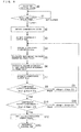
- Fig. 6 is a flowchart illustrating control for detecting a refrigerant composition in the refrigerating and air-conditioning apparatus 100 according to Embodiment 1 of the present invention.
- control for detecting a refrigerant composition refrigerant composition detection control
- a request signal for refrigerant composition detection control from the controller 21 is received by the composition detection means 20, and the composition detection means 20 starts refrigerant composition detection control. Then, the processing proceeds to step S1.
- the composition detection means 20 determines whether a given time period has elapsed.
- step S2 When the given time period has elapsed, the processing proceeds to step S2.
- step S1 is repeated.
- the given time period may be set as a short cycle such as 10 sec or 20 sec.
- the suction-side pressure detection means 11 detects the pressure of the refrigerant at the suction side of the compressor 2
- the suction-side temperature detection means 12 detects the temperature of the refrigerant at the suction side of the compressor 2
- the discharge-side pressure detection means 13 detects the pressure of the refrigerant at the discharge side of the compressor 2
- the rotation speed detection means 14 detects the rotation speed of the compressor 2. Then, the processing proceeds to step S3.
- the output detection means 15 detects power consumption Wdet as an output of the compressor 2. Then, the processing proceeds to step S4.
- the composition detection means 20 assumes and sets the value of the refrigerant composition ⁇ as ⁇ tmp. Then, the processing proceeds to step S5.
- the refrigerant composition ⁇ in the last refrigerant composition detection control may be set as a set value of ⁇ tmp in entering a loop of steps S4 to S11 for the first time.
- the number of loops required for convergence in steps S4 to S11 is reduced, and thereby stabilizing the controllability.
- the composition detection means 20 calculates refrigerant physical properties. Specifically, the composition detection means 20 calculates the refrigerant density ps of the refrigerant at the suction side of the compressor 2, the enthalpy difference ⁇ h in the compression process, and the entropy Ss of the refrigerant at the suction side of the compressor 2 on the basis of the detection results (Ps, Ts, Pt) of the suction-side pressure detection means 11, the suction-side temperature detection means 12, and the discharge-side pressure detection means 13 in step S2, ⁇ tmp set in step S4, and formulas 3, 5, and 6. Then, the processing proceeds to step S6.
- the composition detection means 20 calculates compressor characteristics. Specifically, the composition detection means 20 calculates the volume efficiency ⁇ v and the compressor efficiency ⁇ c on the basis of the detection results (Ps, Ts, Pd, N) of the suction-side pressure detection means 11, the suction-side temperature detection means 12, the discharge-side pressure detection means 13, and the rotation speed detection means 14 in step S2, the detection result Wdet of the output detection means 15 in step S3, ⁇ tmp set in step S4, and formula 4 for the volume efficiency ⁇ v and formula 7 for the compressor efficiency ⁇ c which are obtained by curve-fitting the unit evaluation result of the compressor 2. Then, the processing proceeds to step S7.
- curve fitting the unit evaluation result of the compressor 2 specifies as follows; only the compressor 2 is subjected to an evaluation conducted under a plurality of conditions, and curve-fit the compressor efficiency ⁇ c obtained from the evaluation result to the expansion formula for the compressor efficiency ⁇ c to determine various constants in the expansion formula.
- the composition detection means 20 calculates power consumption Wcal of the compressor 2 on the basis of the detection result (Wdet) of the output detection means 15 in step S3, the refrigerant density ps of the refrigerant at the suction side of the compressor 2 and the enthalpy difference ⁇ h in the compression process which are calculated in step S5, the preset stroke volume Vst, the volume efficiency ⁇ v and the compressor efficiency ⁇ c which are calculated in step S6, and formula 8. Then, the processing proceeds to step S8.
- the composition detection means 20 determines whether the power consumption Wcal calculated in step S7 is equal to or less than Wdet + ⁇ W which is a restricted upper limit.
- step S10 If the power consumption Wcal is equal to or less than Wdet + ⁇ W which is the restricted upper limit, the processing proceeds to step S10.
- step S9 If the power consumption Wcal is not equal to or less than Wdet + ⁇ W which is the restricted upper limit, the processing proceeds to step S9.
- ⁇ W (>0) is an allowable error.
- ⁇ W may be a fixed value, or may be changed on the basis of the difference between Wcal and Wdet + ⁇ W.
- the composition detection means 20 sets, as ⁇ tmp, a value obtained by subtracting a predetermined value ⁇ from ⁇ tmp set in step S4. Then, the processing proceeds to step S4.
- ⁇ may be a fixed value, or may be changed on the basis of the difference between Wcal and Wdet + ⁇ W.
- the composition detection means 20 determines whether the power consumption Wcal calculated in step S7 is equal to or greater than Wdet - ⁇ W which is a restricted lower limit.
- step S12 If the power consumption Wcal is equal to or greater than Wdet - ⁇ W which is the restricted lower limit, the processing proceeds to step S12.
- step S11 If the power consumption Wcal is not equal to or greater than Wdet - ⁇ W which is the restricted lower limit, the processing proceeds to step S11.
- ⁇ W (>0) is an allowable error.
- ⁇ W may be a fixed value, or may be changed on the basis of the difference between Wcal and Wdet - ⁇ W.
- the composition detection means 20 set, as ⁇ tmp, a value obtained by adding a predetermined value ⁇ to ⁇ tmp set in step S4. Then, the processing proceeds to step S4.
- ⁇ may be a fixed value, or may be changed on the basis of the difference between Wcal and Wdet - ⁇ W.
- the composition detection means 20 sets ⁇ tmp as a composition ⁇ of the refrigerant circulating through the refrigeration cycle. Then, the processing proceeds to step S13.
- the composition detection means 20 ends the control for detecting the refrigerant composition.
- steps S5 to S8 are a process for calculating the power consumption of the compressor 2 from the operating state of the compressor 2.
- steps S5 to S8 may be integrated into a single step by assuming all operating states and calculating and tabling the power consumption of the compressor 2.
- R32 and R1234yf are used as the non-azeotropic refrigerant mixture, but another low-boiling-point refrigerant and another high-boiling-point refrigerant may be used.
- a hydrofluoroolefin-based refrigerant having double bonds may be used, a low flammable refrigerant may be used, or a flammable HC-based refrigerant may be used.
- the non-azeotropic refrigerant mixture is composed of a mixture of two refrigerants, but may be composed of a mixture of three or more refrigerants.
- refrigerant compositions of the other refrigerants may be calculated previously by an experiment, simulation, or the like.
- the refrigerant composition of one refrigerant is calculated as in the refrigerating and air-conditioning apparatus 100 according to Embodiment 1, it is also possible to calculate the other refrigerant compositions.
- the refrigerating and air-conditioning apparatus 100 uses the power consumption of the compressor as an output of the compressor 2.
- the connection position of the output detection means 15 may be a primary-side input including inverter loss, or may be a secondary-side input-output not including inverter loss.
- a condition regarding the connection position of the output detection means 15 may be adjusted.
- the power consumption of the compressor 2 is used as the output detected by the output detection means 15, but a current of the compressor 2 may be used.
- the power consumption of the compressor 2 is defined as a product of a voltage, a current, and a power factor, and it has been confirmed in a real machine that the power consumption and the current have a one-to-one correlation under the same operating state of the compressor 2.
- the output detection means 15 may be one (a current sensor) that detects the current of the compressor 2. In this case, when the output detection means 15 is commonalized with one installed for the reason such as overcurrent protection, it is possible to reduce the cost.
- the refrigerating and air-conditioning apparatus 100 detects a refrigerant composition through a control flow as in steps S0 to S13.
- the refrigerating and air-conditioning apparatus 100 detects the composition of the refrigerant in accordance with a simple relationship between the refrigerant composition and the power consumption of the compressor 2.
- the refrigerating and air-conditioning apparatus 100 is able to detect the composition with high accuracy even when the composition of the circulating refrigerant is changed due to the operating condition.
- the refrigerating and air-conditioning apparatus 100 detects a refrigerant composition on the basis of the pressure and the temperature of the refrigerant at the suction side of the compressor 2 and the pressure of the refrigerant at the discharge side of the compressor 2. In other words, once the specifications of the compressor 2 are determined, the refrigerating and air-conditioning apparatus 100 realizes the control for detecting the refrigerant composition, and does not depend on the specifications of the refrigerating and air-conditioning apparatus 100.
- the refrigerating and air-conditioning apparatus 100 does not perform composition detection at a branched refrigerant path.
- the refrigerating and air-conditioning apparatus 100 performs composition detection at a single path of the compression process, and hence enables composition detection even in a gas-liquid two-phase state.
- the compressor 2 of the refrigerating and air-conditioning apparatus 100 is restrained from being damaged, and hence it is possible to suppress reduction of the reliability.
- the refrigerating and air-conditioning apparatus 100 detects a refrigerant composition with the components such as the suction-side pressure detection means 11, the suction-side temperature detection means 12, the discharge-side pressure detection means 13, the rotation speed detection means 14, and the output detection means 15.
- the refrigerating and air-conditioning apparatus 100 does not use expensive components such as a bypass composed of a heat exchanger, an expansion mechanism, and the like and a liquid level detector of an accumulator, and thus the detection of refrigerant composition is able to be performed at low cost.
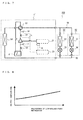
- Fig. 7 shows an example of a refrigerant circuit configuration of a refrigerating and air-conditioning apparatus 200 according to Embodiment 2 of the present invention.
- the same parts as those in Embodiment 1 are denoted by the same reference characters, and the difference from Embodiment 1 will be mainly described.
- the unit evaluation of the compressor 2 is conducted under a plurality of conditions, and the unit evaluation result and the expansion formula for the compressor efficiency ⁇ c are curve-fitted to each other to determine various constants in the expansion formula for ⁇ v.
- the composition detection means 20 of the refrigerating and air-conditioning apparatus 100 according to Embodiment 1 performs unit evaluation and calculation such as curve fitting for calculating ⁇ v and calculates the refrigerant composition ⁇
- the composition detection means 20 of the refrigerating apparatus 200 according to Embodiment 2 calculates the refrigerant composition ⁇ without using formula 4.
- an outdoor unit 51 including an accumulator 6, a compressor 2, a four-way valve 53, an outdoor heat exchanger 54, etc. and indoor units 52 each including an indoor heat exchanger 57 and a pressure reducing mechanism 56 are connected to each other via a liquid extension pipe 55 and a gas extension pipe 58 to form a refrigeration cycle.
- Fig. 7 illustrates an example where the refrigerating and air-conditioning apparatus 200 includes two indoor units 52, but the present invention is not limited thereto, and the refrigerating and air-conditioning apparatus 200 may include three or more indoor units 52.
- the outdoor unit 51 includes the compressor 2 which compresses a refrigerant, the four-way valve 53 which switches a refrigerant flow path, the outdoor heat exchanger 54 which serves as a condenser during a cooling operation and as an evaporator during a heating operation, and the accumulator 6 which stores an excess refrigerant.
- the outdoor unit 51 includes the suction-side pressure detection means 11, the suction-side temperature detection means 12, the discharge-side pressure detection means 13, and the rotation speed detection means 14 which are described in Embodiment 1.
- the outdoor unit 51 includes discharge-side temperature detection means 16 which detects the temperature of the refrigerant discharged from the compressor 2. It should be noted that the outdoor unit 51 does not include the output detection means 15 described in Embodiment 1.
- the outdoor unit 51 includes composition detection means 20 which detects a refrigerant composition on the basis of detection results of these detection means 11 to 14 and 16; and a controller 21 which integrally controls the rotation speed of the compressor 2 and various devices.
- Each indoor unit 52 includes the indoor heat exchanger 57 which serves as an evaporator during a cooling operation and as a condenser during a heating operation; and the pressure reducing mechanism 56 which reduces the pressure of the refrigerant to expand the refrigerant.
- the liquid extension pipe 55 and the gas extension pipe 58 are pipes connecting the outdoor unit 51 to the indoor units 52.
- the liquid extension pipe 55 is connected at one end to the outdoor heat exchanger 54 and connected another end to each pressure reducing mechanism 56.
- the gas extension pipe 58 is connected at one end to the four-way valve 53 and connected at another end to each indoor heat exchanger 57.
- the four-way valve 53 switches the refrigerant flow path.
- the four-way valve 53 is switched to connect the compressor 2 to the outdoor heat exchanger 54 and connect the accumulator 6 to each indoor heat exchanger 57 during a cooling operation, and is switched to connected the compressor 2 to each indoor heat exchanger 57 and connect the outdoor heat exchanger 54 to the accumulator 6 during a heating operation.
- the discharge-side temperature detection means 16 detects the temperature of the refrigerant discharged from the compressor 2 (high-pressure-side refrigerant pressure).
- the discharge-side temperature detection means 16 is connected to the composition detection means 20.
- Fig. 7 illustrates an example where the discharge-side temperature detection means 16 is installed on a refrigerant pipe connecting the accumulator 6 to the compressor 2, but the present invention is not limited thereto.
- the discharge-side temperature detection means 16 may be installed within the compressor 2 and at a position after the refrigerant is compressed (a position after a compression process). Thus, it is possible to detect a refrigerant composition with high accuracy.
- the composition detection means 20 has stored therein a function described in formula 9, in addition to the functions described in formulas 5 to 7 described in Embodiment 1.
- the composition detection means 20 is able to calculate the temperature of the refrigerant at the discharge side of the compressor 2 on the basis of detection results of the suction-side pressure detection means 11, the suction-side temperature detection means 12, the discharge-side pressure detection means 13, and the rotation speed detection means 14, the above formulas 5 to 7, and formula 9.
- the composition detection means 20 calculates a refrigerant composition on the basis of the calculated refrigerant temperature and a detection result of the discharge-side temperature detection means 16.
- formula 9 is obtained from formulas 5 to 7.
- the composition detection means 20 of the refrigerating and air-conditioning apparatus 200 calculates the temperature T of the refrigerant at the discharge side of the compressor 2 on the basis of the detection results of the suction-side pressure detection means 11, the suction-side temperature detection means 12, the discharge-side pressure detection means 13, and the rotation speed detection means 14 and formula 9.
- the composition detection means 20 calculates a refrigerant composition on the basis of the calculated temperature T of the refrigerant at the discharge side and the detection result of the discharge-side temperature detection means 16.
- the method for calculating a refrigerant composition refer to a description of Fig. 9 described later.
- Fig. 8 is a graph illustrating a relationship between the proportion of a low-boiling-point refrigerant included in the circulating refrigerant and the temperature at the discharge side of the compressor 2.
- the temperature of the refrigerant at the discharge side of the compressor 2 when the proportion of the low-boiling-point refrigerant (the composition ratio of the low-boiling-point refrigerant) is changed will be described. It should be noted that in Fig. 8 as well, similarly to Figs.
- the pressure of the refrigerant at the suction side of the compressor 2, the pressure of the refrigerant at the discharge side of the compressor 2, subcooling at the outlet of the condenser 3, and superheat at the outlet of the evaporator 5 are fixed, and the composition of the circulating refrigerant is changed.
- the temperature of the refrigerant at the discharge side of the compressor 2 monotonously increases.
- the proportion of the refrigerant composition and the temperature of the refrigerant at the discharge side of the compressor 2 have a simple correspondence relationship. Therefore, the composition detection means 20 of the refrigerating and air-conditioning apparatus 200 according to Embodiment 2 is able to assuredly detect a refrigerant composition.
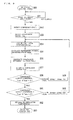
- Fig. 9 is a flowchart illustrating control for detecting a refrigerant composition in the refrigerating and air-conditioning apparatus 200 according to Embodiment 2 of the present invention. With reference to Fig. 9 , a method for detecting a refrigerant composition will be described.
- a request signal for refrigerant composition detection control from the controller 21 is received by the composition detection means 20, and the composition detection means 20 starts refrigerant composition detection control. Then, the processing proceeds to step S51.
- the composition detection means 20 determines whether a given time period has elapsed.
- step S52 When the given time period has elapsed, the processing proceeds to step S52.
- step S51 is repeated.
- the given time period may be set as a short cycle such as 10 sec or 20 sec.
- the suction-side pressure detection means 11 detects the pressure of the refrigerant at the suction side of the compressor 2
- the suction-side temperature detection means 12 detects the temperature of the refrigerant at the suction side of the compressor 2
- the discharge-side pressure detection means 13 detects the pressure of the refrigerant at the discharge side of the compressor 2
- the rotation speed detection means 14 detects the rotation speed of the compressor 2. Then, the processing proceeds to step S53.
- the discharge-side temperature detection means 16 detects a temperature Tdet of the refrigerant at the discharge side of the compressor 2. Then, the processing proceeds to step S54.
- the composition detection means 20 sets the value of the refrigerant composition ⁇ as ⁇ tmp. Then, the processing proceeds to step S55.
- the refrigerant composition ⁇ in the last refrigerant composition detection control may be set as a set value of ⁇ tmp in entering a loop of steps S54 to S61 for the first time.
- the number of loops required for convergence in steps S54 to S61 is small, and it is possible to stabilize the controllability.
- the composition detection means 20 calculates refrigerant physical properties. Specifically, the composition detection means 20 calculates the entropy Ss of the refrigerant at the suction side of the compressor 2 and the enthalpy difference ⁇ h in the compression process on the basis of the detection results (Ps, Ts, Td) of the suction-side pressure detection means 11, the suction-side temperature detection means 12, and the discharge-side pressure detection means 13 in step S2, ⁇ tmp set in step S54, and formulas 3, 5, and 6. Then, the processing proceeds to step S56.
- the composition detection means 20 calculates a compressor characteristic. Specifically, the composition detection means 20 calculates compressor efficiency ⁇ c on the basis of the detection results (Ps, Ts, Pd, N) of the suction-side pressure detection means 11, the suction-side temperature detection means 12, the discharge-side pressure detection means 13, and the rotation speed detection means 14 in step S52, the detection result Tdet of the discharge-side temperature detection means 16 in step S53, ⁇ tmp set in step S54, and formula 7 for the compressor efficiency ⁇ c which is obtained by curve-fitting the unit evaluation result of the compressor 2. Then, the processing proceeds to step S57.
- the composition detection means 20 calculates a temperature Tcal of the refrigerant at the discharge side of the compressor 2 on the basis of the detection result (Tdet) of the discharge-side temperature detection means 16 in step S53, the enthalpy difference ⁇ h in the compression process which is calculated in step S55, the compressor efficiency ⁇ c which is calculated in step S56, and formula 9. Then, the processing proceeds to step S58.
- the composition detection means 20 determines whether the temperature Tcal calculated in step S57 is equal to or less than Tdet + ⁇ T which is a restricted upper limit.
- step S60 If the temperature Tcal is equal to or less than Tdet + ⁇ T which is the restricted upper limit, the processing proceeds to step S60.
- ⁇ T (>0) is an allowable error.
- ⁇ T may be a fixed value, or may be changed on the basis of the difference between Tcal and Tdet + ⁇ T.
- the composition detection means 20 sets, as ⁇ tmp, a value obtained by subtracting a predetermined value ⁇ T from ⁇ tmp set in step S54. Then, the processing proceeds to step S54.
- ⁇ T may be a fixed value, or may be changed on the basis of the difference between Tcal and Tdet + ⁇ T.
- the composition detection means 20 determines whether the temperature Tcal calculated in step S57 is equal to or greater than Tdet - ⁇ T which is a restricted lower limit.
- ⁇ T (>0) is an allowable error.
- ⁇ T may be a fixed value, or may be changed on the basis of the difference between Tcal and Tdet - ⁇ T.
- the composition detection means 20 sets, as ⁇ tmp, a value obtained by adding a predetermined value ⁇ T to ⁇ tmp set in step S54. Then, the processing proceeds to step S54.
- ⁇ T may be a fixed value, or may be changed on the basis of the difference between Tcal and Tdet - ⁇ T.
- the composition detection means 20 sets ⁇ tmp as a composition ⁇ of the refrigerant circulating through the refrigeration cycle. Then, the processing proceeds to step S63.
- the composition detection means 20 ends the control for detecting the refrigerant composition.
- the refrigerating and air-conditioning apparatus 200 detects a refrigerant composition through a control flow as in steps S50 to S63.
- the refrigerating and air-conditioning apparatus 200 detects the composition of the refrigerant in accordance with a simple relationship between the refrigerant composition and the temperature of the refrigerant at the discharge side of the compressor 2.
- the refrigerating and air-conditioning apparatus 200 is able to detect the composition with high accuracy even when the composition of the circulating refrigerant is changed depending on the operating condition.
- the refrigerating and air-conditioning apparatus 200 detects a refrigerant composition on the basis of the pressure and the temperature of the refrigerant at the suction side of the compressor 2 and the temperature of the refrigerant at the discharge side of the compressor 2.
- the control for detecting the refrigerant composition is capable of being realized when the specifications of the compressor 2 alone are determined, and does not depend on the specifications of the refrigerating and air-conditioning apparatus 200 (unit).
- the refrigerating and air-conditioning apparatus 100 does not perform composition detection at a branched refrigerant path.
- the refrigerating and air-conditioning apparatus 100 performs composition detection at a single path of the compression process, and hence enables composition detection even in a gas-liquid two-phase state.
- the compressor 2 of the refrigerating and air-conditioning apparatus 100 is restrained from being damaged, and hence it is possible to suppress reduction of the reliability.
- the refrigerating and air-conditioning apparatus 200 detects a refrigerant composition with the components such as the suction-side pressure detection means 11, the suction-side temperature detection means 12, the discharge-side pressure detection means 13, the rotation speed detection means 14, and the output detection means 15.
- the refrigerating and air-conditioning apparatus 200 does not use expensive components such as a bypass composed of a heat exchanger, an expansion mechanism, and the like and a liquid level detector of an accumulator, and thus is able to detect a refrigerant composition at low cost.
Landscapes
- Engineering & Computer Science (AREA)
- Physics & Mathematics (AREA)
- Mechanical Engineering (AREA)
- Thermal Sciences (AREA)
- General Engineering & Computer Science (AREA)
- Air Conditioning Control Device (AREA)
- Compression-Type Refrigeration Machines With Reversible Cycles (AREA)
Applications Claiming Priority (1)
| Application Number | Priority Date | Filing Date | Title |
|---|---|---|---|
| PCT/JP2011/003895 WO2013005260A1 (fr) | 2011-07-07 | 2011-07-07 | Dispositif de réfrigération et de climatisation et procédé pour commander le dispositif de réfrigération et de climatisation |
Publications (3)
| Publication Number | Publication Date |
|---|---|
| EP2730863A1 true EP2730863A1 (fr) | 2014-05-14 |
| EP2730863A4 EP2730863A4 (fr) | 2015-02-25 |
| EP2730863B1 EP2730863B1 (fr) | 2020-06-03 |
Family
ID=47436636
Family Applications (1)
| Application Number | Title | Priority Date | Filing Date |
|---|---|---|---|
| EP11868973.6A Active EP2730863B1 (fr) | 2011-07-07 | 2011-07-07 | Dispositif de réfrigération et de climatisation et procédé pour commander le dispositif de réfrigération et de climatisation |
Country Status (5)
| Country | Link |
|---|---|
| US (1) | US9453671B2 (fr) |
| EP (1) | EP2730863B1 (fr) |
| JP (1) | JP5791716B2 (fr) |
| CN (1) | CN103688117B (fr) |
| WO (1) | WO2013005260A1 (fr) |
Cited By (2)
| Publication number | Priority date | Publication date | Assignee | Title |
|---|---|---|---|---|
| CN106813917A (zh) * | 2017-03-14 | 2017-06-09 | 广东志高暖通设备股份有限公司 | 一种空调、检测冷媒异常节流的装置与方法 |
| EP3764027A4 (fr) * | 2018-03-05 | 2021-05-19 | Panasonic Intellectual Property Management Co., Ltd. | Dispositif à cycle de réfrigération |
Families Citing this family (9)
| Publication number | Priority date | Publication date | Assignee | Title |
|---|---|---|---|---|
| US9982930B2 (en) * | 2014-02-05 | 2018-05-29 | Lennox Industries Inc. | System for controlling operation of an HVAC system |
| KR102460483B1 (ko) * | 2016-02-04 | 2022-10-31 | 엘지전자 주식회사 | 인공지능 기능을 수반하는 공기 조화기 및 그 제어방법 |
| JP6747109B2 (ja) * | 2016-07-06 | 2020-08-26 | ダイキン工業株式会社 | スクロール圧縮機 |
| JP6767841B2 (ja) | 2016-10-14 | 2020-10-14 | サンデン・オートモーティブクライメイトシステム株式会社 | 車両用空気調和装置 |
| JP6678762B2 (ja) * | 2016-10-28 | 2020-04-08 | 三菱電機株式会社 | スクロール圧縮機、冷凍サイクル装置およびシェル |
| TWI666532B (zh) * | 2017-10-05 | 2019-07-21 | 群光電能科技股份有限公司 | 效能預測方法 |
| US11067319B2 (en) * | 2018-03-05 | 2021-07-20 | Johnson Controls Technology Company | Heat exchanger with multiple conduits and valve control system |
| CN110375466B (zh) | 2018-04-13 | 2022-10-28 | 开利公司 | 用于空气源热泵系统的制冷剂泄露的检测装置和方法 |
| US10895393B2 (en) * | 2018-07-06 | 2021-01-19 | Johnson Controls Technology Company | Variable refrigerant flow system with pressure optimization using extremum-seeking control |
Family Cites Families (15)
| Publication number | Priority date | Publication date | Assignee | Title |
|---|---|---|---|---|
| JP3178103B2 (ja) * | 1992-08-31 | 2001-06-18 | 株式会社日立製作所 | 冷凍サイクル |
| CN1079528C (zh) * | 1993-10-28 | 2002-02-20 | 株式会社日立制作所 | 制冷循环及其控制方法 |
| DE69526979T2 (de) * | 1994-07-21 | 2003-02-06 | Mitsubishi Electric Corp | Klimagerät mit nichtazeotropischem Kältemittel und Steuerungsinformations-Erfassungsgerät |
| CN1083093C (zh) * | 1994-08-30 | 2002-04-17 | 株式会社东芝 | 空调器 |
| JPH08254363A (ja) | 1995-03-15 | 1996-10-01 | Toshiba Corp | 空調制御装置 |
| JP3463710B2 (ja) * | 1995-03-27 | 2003-11-05 | 三菱電機株式会社 | 非共沸混合冷媒搭載の冷凍装置 |
| JP3655681B2 (ja) * | 1995-06-23 | 2005-06-02 | 三菱電機株式会社 | 冷媒循環システム |
| JPH10122711A (ja) * | 1996-10-18 | 1998-05-15 | Matsushita Electric Ind Co Ltd | 冷凍サイクル制御装置 |
| JPH10160273A (ja) * | 1996-12-02 | 1998-06-19 | Hitachi Ltd | 空気調和装置 |
| JP3185722B2 (ja) * | 1997-08-20 | 2001-07-11 | 三菱電機株式会社 | 冷凍空調装置および冷凍空調装置の冷媒組成を求める方法 |
| JP2001099501A (ja) | 1999-09-30 | 2001-04-13 | Yamaha Motor Co Ltd | 非共沸冷媒を使用した冷媒循環式熱移動装置 |
| US6701725B2 (en) * | 2001-05-11 | 2004-03-09 | Field Diagnostic Services, Inc. | Estimating operating parameters of vapor compression cycle equipment |
| US8443624B2 (en) | 2008-06-16 | 2013-05-21 | Mitsubishi Electric Corporation | Non-Azeotropic refrigerant mixture and refrigeration cycle apparatus |
| JP2010002090A (ja) * | 2008-06-19 | 2010-01-07 | Panasonic Corp | 冷凍サイクル装置 |
| US20100122545A1 (en) * | 2008-11-19 | 2010-05-20 | E. I. Du Pont De Nemours And Company | Tetrafluoropropene compositions and uses thereof |
-
2011
- 2011-07-07 JP JP2013522369A patent/JP5791716B2/ja active Active
- 2011-07-07 WO PCT/JP2011/003895 patent/WO2013005260A1/fr active Application Filing
- 2011-07-07 US US14/128,167 patent/US9453671B2/en active Active
- 2011-07-07 EP EP11868973.6A patent/EP2730863B1/fr active Active
- 2011-07-07 CN CN201180072135.3A patent/CN103688117B/zh active Active
Cited By (2)
| Publication number | Priority date | Publication date | Assignee | Title |
|---|---|---|---|---|
| CN106813917A (zh) * | 2017-03-14 | 2017-06-09 | 广东志高暖通设备股份有限公司 | 一种空调、检测冷媒异常节流的装置与方法 |
| EP3764027A4 (fr) * | 2018-03-05 | 2021-05-19 | Panasonic Intellectual Property Management Co., Ltd. | Dispositif à cycle de réfrigération |
Also Published As
| Publication number | Publication date |
|---|---|
| CN103688117B (zh) | 2016-04-06 |
| EP2730863A4 (fr) | 2015-02-25 |
| US9453671B2 (en) | 2016-09-27 |
| WO2013005260A1 (fr) | 2013-01-10 |
| EP2730863B1 (fr) | 2020-06-03 |
| CN103688117A (zh) | 2014-03-26 |
| JPWO2013005260A1 (ja) | 2015-02-23 |
| US20140123693A1 (en) | 2014-05-08 |
| JP5791716B2 (ja) | 2015-10-07 |
Similar Documents
| Publication | Publication Date | Title |
|---|---|---|
| EP2730863B1 (fr) | Dispositif de réfrigération et de climatisation et procédé pour commander le dispositif de réfrigération et de climatisation | |
| US11131490B2 (en) | Refrigeration device having condenser unit connected to compressor unit with on-site pipe interposed therebetween and remote from the compressor unit | |
| EP3683524B1 (fr) | Dispositif frigorifique | |
| EP3026371B1 (fr) | Appareil de circuit de refrigeration | |
| US10323862B2 (en) | Air conditioning unit having dynamic target condensing and evaporating values based on load requirements | |
| US10753660B2 (en) | Air-conditioning apparatus | |
| US20150362238A1 (en) | Refrigeration cycle apparatus and method of controlling refrigeration cycle apparatus | |
| KR101901540B1 (ko) | 공기 조화 장치 | |
| EP2878899B1 (fr) | Climatiseur | |
| WO2020115935A1 (fr) | Système de conditionnement d'air | |
| WO2013093981A1 (fr) | Dispositif pour cycle de réfrigération | |
| JP2011047552A (ja) | 冷凍サイクル装置及び空気調和装置 | |
| EP3757483A1 (fr) | Appareil de cycle de réfrigération et appareil de climatisation équipé de celui-ci | |
| JP2017075760A (ja) | 空気調和機 | |
| JP2019002639A (ja) | 空気調和機の冷媒漏洩検知方法、および、空気調和機 | |
| EP3401612A1 (fr) | Climatiseur et procédé de commande de climatiseur | |
| JP2943613B2 (ja) | 非共沸混合冷媒を用いた冷凍空調装置 | |
| GB2562639A (en) | Refrigeration device | |
| JP6537629B2 (ja) | 空気調和装置 | |
| JPWO2016207992A1 (ja) | 空気調和機 | |
| JP2008249240A (ja) | コンデンシングユニット及びそれを備えた冷凍装置 | |
| GB2618030A (en) | Refrigeration cycle device | |
| AU1550301A (en) | Refrigerating device | |
| JPH10253187A (ja) | 空気調和機 |
Legal Events
| Date | Code | Title | Description |
|---|---|---|---|
| PUAI | Public reference made under article 153(3) epc to a published international application that has entered the european phase |
Free format text: ORIGINAL CODE: 0009012 |
|
| 17P | Request for examination filed |
Effective date: 20140201 |
|
| AK | Designated contracting states |
Kind code of ref document: A1 Designated state(s): AL AT BE BG CH CY CZ DE DK EE ES FI FR GB GR HR HU IE IS IT LI LT LU LV MC MK MT NL NO PL PT RO RS SE SI SK SM TR |
|
| DAX | Request for extension of the european patent (deleted) | ||
| A4 | Supplementary search report drawn up and despatched |
Effective date: 20150127 |
|
| RIC1 | Information provided on ipc code assigned before grant |
Ipc: F25B 1/00 20060101ALI20150121BHEP Ipc: F25B 13/00 20060101ALI20150121BHEP Ipc: F25B 49/00 20060101ALI20150121BHEP Ipc: F25B 49/02 20060101AFI20150121BHEP |
|
| STAA | Information on the status of an ep patent application or granted ep patent |
Free format text: STATUS: EXAMINATION IS IN PROGRESS |
|
| 17Q | First examination report despatched |
Effective date: 20161221 |
|
| GRAP | Despatch of communication of intention to grant a patent |
Free format text: ORIGINAL CODE: EPIDOSNIGR1 |
|
| STAA | Information on the status of an ep patent application or granted ep patent |
Free format text: STATUS: GRANT OF PATENT IS INTENDED |
|
| INTG | Intention to grant announced |
Effective date: 20191218 |
|
| GRAS | Grant fee paid |
Free format text: ORIGINAL CODE: EPIDOSNIGR3 |
|
| GRAA | (expected) grant |
Free format text: ORIGINAL CODE: 0009210 |
|
| STAA | Information on the status of an ep patent application or granted ep patent |
Free format text: STATUS: THE PATENT HAS BEEN GRANTED |
|
| AK | Designated contracting states |
Kind code of ref document: B1 Designated state(s): AL AT BE BG CH CY CZ DE DK EE ES FI FR GB GR HR HU IE IS IT LI LT LU LV MC MK MT NL NO PL PT RO RS SE SI SK SM TR |
|
| REG | Reference to a national code |
Ref country code: GB Ref legal event code: FG4D |
|
| REG | Reference to a national code |
Ref country code: CH Ref legal event code: EP Ref country code: AT Ref legal event code: REF Ref document number: 1277421 Country of ref document: AT Kind code of ref document: T Effective date: 20200615 |
|
| REG | Reference to a national code |
Ref country code: DE Ref legal event code: R096 Ref document number: 602011067195 Country of ref document: DE |
|
| REG | Reference to a national code |
Ref country code: LT Ref legal event code: MG4D |
|
| PG25 | Lapsed in a contracting state [announced via postgrant information from national office to epo] |
Ref country code: SE Free format text: LAPSE BECAUSE OF FAILURE TO SUBMIT A TRANSLATION OF THE DESCRIPTION OR TO PAY THE FEE WITHIN THE PRESCRIBED TIME-LIMIT Effective date: 20200603 Ref country code: LT Free format text: LAPSE BECAUSE OF FAILURE TO SUBMIT A TRANSLATION OF THE DESCRIPTION OR TO PAY THE FEE WITHIN THE PRESCRIBED TIME-LIMIT Effective date: 20200603 Ref country code: NO Free format text: LAPSE BECAUSE OF FAILURE TO SUBMIT A TRANSLATION OF THE DESCRIPTION OR TO PAY THE FEE WITHIN THE PRESCRIBED TIME-LIMIT Effective date: 20200903 Ref country code: GR Free format text: LAPSE BECAUSE OF FAILURE TO SUBMIT A TRANSLATION OF THE DESCRIPTION OR TO PAY THE FEE WITHIN THE PRESCRIBED TIME-LIMIT Effective date: 20200904 Ref country code: FI Free format text: LAPSE BECAUSE OF FAILURE TO SUBMIT A TRANSLATION OF THE DESCRIPTION OR TO PAY THE FEE WITHIN THE PRESCRIBED TIME-LIMIT Effective date: 20200603 |
|
| REG | Reference to a national code |
Ref country code: NL Ref legal event code: MP Effective date: 20200603 |
|
| PG25 | Lapsed in a contracting state [announced via postgrant information from national office to epo] |
Ref country code: LV Free format text: LAPSE BECAUSE OF FAILURE TO SUBMIT A TRANSLATION OF THE DESCRIPTION OR TO PAY THE FEE WITHIN THE PRESCRIBED TIME-LIMIT Effective date: 20200603 Ref country code: HR Free format text: LAPSE BECAUSE OF FAILURE TO SUBMIT A TRANSLATION OF THE DESCRIPTION OR TO PAY THE FEE WITHIN THE PRESCRIBED TIME-LIMIT Effective date: 20200603 Ref country code: BG Free format text: LAPSE BECAUSE OF FAILURE TO SUBMIT A TRANSLATION OF THE DESCRIPTION OR TO PAY THE FEE WITHIN THE PRESCRIBED TIME-LIMIT Effective date: 20200903 Ref country code: RS Free format text: LAPSE BECAUSE OF FAILURE TO SUBMIT A TRANSLATION OF THE DESCRIPTION OR TO PAY THE FEE WITHIN THE PRESCRIBED TIME-LIMIT Effective date: 20200603 |
|
| REG | Reference to a national code |
Ref country code: AT Ref legal event code: MK05 Ref document number: 1277421 Country of ref document: AT Kind code of ref document: T Effective date: 20200603 |
|
| PG25 | Lapsed in a contracting state [announced via postgrant information from national office to epo] |
Ref country code: AL Free format text: LAPSE BECAUSE OF FAILURE TO SUBMIT A TRANSLATION OF THE DESCRIPTION OR TO PAY THE FEE WITHIN THE PRESCRIBED TIME-LIMIT Effective date: 20200603 Ref country code: NL Free format text: LAPSE BECAUSE OF FAILURE TO SUBMIT A TRANSLATION OF THE DESCRIPTION OR TO PAY THE FEE WITHIN THE PRESCRIBED TIME-LIMIT Effective date: 20200603 |
|
| PG25 | Lapsed in a contracting state [announced via postgrant information from national office to epo] |
Ref country code: IT Free format text: LAPSE BECAUSE OF FAILURE TO SUBMIT A TRANSLATION OF THE DESCRIPTION OR TO PAY THE FEE WITHIN THE PRESCRIBED TIME-LIMIT Effective date: 20200603 Ref country code: RO Free format text: LAPSE BECAUSE OF FAILURE TO SUBMIT A TRANSLATION OF THE DESCRIPTION OR TO PAY THE FEE WITHIN THE PRESCRIBED TIME-LIMIT Effective date: 20200603 Ref country code: PT Free format text: LAPSE BECAUSE OF FAILURE TO SUBMIT A TRANSLATION OF THE DESCRIPTION OR TO PAY THE FEE WITHIN THE PRESCRIBED TIME-LIMIT Effective date: 20201006 Ref country code: CZ Free format text: LAPSE BECAUSE OF FAILURE TO SUBMIT A TRANSLATION OF THE DESCRIPTION OR TO PAY THE FEE WITHIN THE PRESCRIBED TIME-LIMIT Effective date: 20200603 Ref country code: ES Free format text: LAPSE BECAUSE OF FAILURE TO SUBMIT A TRANSLATION OF THE DESCRIPTION OR TO PAY THE FEE WITHIN THE PRESCRIBED TIME-LIMIT Effective date: 20200603 Ref country code: AT Free format text: LAPSE BECAUSE OF FAILURE TO SUBMIT A TRANSLATION OF THE DESCRIPTION OR TO PAY THE FEE WITHIN THE PRESCRIBED TIME-LIMIT Effective date: 20200603 Ref country code: EE Free format text: LAPSE BECAUSE OF FAILURE TO SUBMIT A TRANSLATION OF THE DESCRIPTION OR TO PAY THE FEE WITHIN THE PRESCRIBED TIME-LIMIT Effective date: 20200603 Ref country code: SM Free format text: LAPSE BECAUSE OF FAILURE TO SUBMIT A TRANSLATION OF THE DESCRIPTION OR TO PAY THE FEE WITHIN THE PRESCRIBED TIME-LIMIT Effective date: 20200603 |
|
| PG25 | Lapsed in a contracting state [announced via postgrant information from national office to epo] |
Ref country code: SK Free format text: LAPSE BECAUSE OF FAILURE TO SUBMIT A TRANSLATION OF THE DESCRIPTION OR TO PAY THE FEE WITHIN THE PRESCRIBED TIME-LIMIT Effective date: 20200603 Ref country code: PL Free format text: LAPSE BECAUSE OF FAILURE TO SUBMIT A TRANSLATION OF THE DESCRIPTION OR TO PAY THE FEE WITHIN THE PRESCRIBED TIME-LIMIT Effective date: 20200603 Ref country code: IS Free format text: LAPSE BECAUSE OF FAILURE TO SUBMIT A TRANSLATION OF THE DESCRIPTION OR TO PAY THE FEE WITHIN THE PRESCRIBED TIME-LIMIT Effective date: 20201003 |
|
| REG | Reference to a national code |
Ref country code: CH Ref legal event code: PL |
|
| REG | Reference to a national code |
Ref country code: DE Ref legal event code: R097 Ref document number: 602011067195 Country of ref document: DE |
|
| PG25 | Lapsed in a contracting state [announced via postgrant information from national office to epo] |
Ref country code: MC Free format text: LAPSE BECAUSE OF FAILURE TO SUBMIT A TRANSLATION OF THE DESCRIPTION OR TO PAY THE FEE WITHIN THE PRESCRIBED TIME-LIMIT Effective date: 20200603 |
|
| PLBE | No opposition filed within time limit |
Free format text: ORIGINAL CODE: 0009261 |
|
| STAA | Information on the status of an ep patent application or granted ep patent |
Free format text: STATUS: NO OPPOSITION FILED WITHIN TIME LIMIT |
|
| REG | Reference to a national code |
Ref country code: BE Ref legal event code: MM Effective date: 20200731 |
|
| PG25 | Lapsed in a contracting state [announced via postgrant information from national office to epo] |
Ref country code: LU Free format text: LAPSE BECAUSE OF NON-PAYMENT OF DUE FEES Effective date: 20200707 Ref country code: FR Free format text: LAPSE BECAUSE OF NON-PAYMENT OF DUE FEES Effective date: 20200803 Ref country code: CH Free format text: LAPSE BECAUSE OF NON-PAYMENT OF DUE FEES Effective date: 20200731 Ref country code: DK Free format text: LAPSE BECAUSE OF FAILURE TO SUBMIT A TRANSLATION OF THE DESCRIPTION OR TO PAY THE FEE WITHIN THE PRESCRIBED TIME-LIMIT Effective date: 20200603 Ref country code: IE Free format text: LAPSE BECAUSE OF NON-PAYMENT OF DUE FEES Effective date: 20200707 Ref country code: LI Free format text: LAPSE BECAUSE OF NON-PAYMENT OF DUE FEES Effective date: 20200731 |
|
| 26N | No opposition filed |
Effective date: 20210304 |
|
| PG25 | Lapsed in a contracting state [announced via postgrant information from national office to epo] |
Ref country code: BE Free format text: LAPSE BECAUSE OF NON-PAYMENT OF DUE FEES Effective date: 20200731 Ref country code: SI Free format text: LAPSE BECAUSE OF FAILURE TO SUBMIT A TRANSLATION OF THE DESCRIPTION OR TO PAY THE FEE WITHIN THE PRESCRIBED TIME-LIMIT Effective date: 20200603 |
|
| PG25 | Lapsed in a contracting state [announced via postgrant information from national office to epo] |
Ref country code: TR Free format text: LAPSE BECAUSE OF FAILURE TO SUBMIT A TRANSLATION OF THE DESCRIPTION OR TO PAY THE FEE WITHIN THE PRESCRIBED TIME-LIMIT Effective date: 20200603 Ref country code: MT Free format text: LAPSE BECAUSE OF FAILURE TO SUBMIT A TRANSLATION OF THE DESCRIPTION OR TO PAY THE FEE WITHIN THE PRESCRIBED TIME-LIMIT Effective date: 20200603 Ref country code: CY Free format text: LAPSE BECAUSE OF FAILURE TO SUBMIT A TRANSLATION OF THE DESCRIPTION OR TO PAY THE FEE WITHIN THE PRESCRIBED TIME-LIMIT Effective date: 20200603 |
|
| PG25 | Lapsed in a contracting state [announced via postgrant information from national office to epo] |
Ref country code: MK Free format text: LAPSE BECAUSE OF FAILURE TO SUBMIT A TRANSLATION OF THE DESCRIPTION OR TO PAY THE FEE WITHIN THE PRESCRIBED TIME-LIMIT Effective date: 20200603 |
|
| REG | Reference to a national code |
Ref country code: DE Ref legal event code: R084 Ref document number: 602011067195 Country of ref document: DE |
|
| REG | Reference to a national code |
Ref country code: GB Ref legal event code: 746 Effective date: 20230104 |
|
| P01 | Opt-out of the competence of the unified patent court (upc) registered |
Effective date: 20230512 |
|
| PGFP | Annual fee paid to national office [announced via postgrant information from national office to epo] |
Ref country code: GB Payment date: 20230601 Year of fee payment: 13 |
|
| PGFP | Annual fee paid to national office [announced via postgrant information from national office to epo] |
Ref country code: DE Payment date: 20230531 Year of fee payment: 13 |