EP2730516B1 - Vorrichtung zum Gruppieren und Transportieren einer Batterie von Hülsen, die für die Erstellung von Verpackungen bestimmt sind - Google Patents
Vorrichtung zum Gruppieren und Transportieren einer Batterie von Hülsen, die für die Erstellung von Verpackungen bestimmt sind Download PDFInfo
- Publication number
- EP2730516B1 EP2730516B1 EP13189224.2A EP13189224A EP2730516B1 EP 2730516 B1 EP2730516 B1 EP 2730516B1 EP 13189224 A EP13189224 A EP 13189224A EP 2730516 B1 EP2730516 B1 EP 2730516B1
- Authority
- EP
- European Patent Office
- Prior art keywords
- transport device
- uprights
- top panel
- stack
- base
- Prior art date
- Legal status (The legal status is an assumption and is not a legal conclusion. Google has not performed a legal analysis and makes no representation as to the accuracy of the status listed.)
- Active
Links
Images


Classifications
-
- B—PERFORMING OPERATIONS; TRANSPORTING
- B65—CONVEYING; PACKING; STORING; HANDLING THIN OR FILAMENTARY MATERIAL
- B65D—CONTAINERS FOR STORAGE OR TRANSPORT OF ARTICLES OR MATERIALS, e.g. BAGS, BARRELS, BOTTLES, BOXES, CANS, CARTONS, CRATES, DRUMS, JARS, TANKS, HOPPERS, FORWARDING CONTAINERS; ACCESSORIES, CLOSURES, OR FITTINGS THEREFOR; PACKAGING ELEMENTS; PACKAGES
- B65D71/00—Bundles of articles held together by packaging elements for convenience of storage or transport, e.g. portable segregating carrier for plural receptacles such as beer cans or pop bottles; Bales of material
- B65D71/06—Packaging elements holding or encircling completely or almost completely the bundle of articles, e.g. wrappers
- B65D71/12—Packaging elements holding or encircling completely or almost completely the bundle of articles, e.g. wrappers the packaging elements, e.g. wrappers being formed by folding a single blank
- B65D71/14—Packaging elements holding or encircling completely or almost completely the bundle of articles, e.g. wrappers the packaging elements, e.g. wrappers being formed by folding a single blank having the shape of a tube, without, or not being characterised by, end walls
- B65D71/16—Packaging elements holding or encircling completely or almost completely the bundle of articles, e.g. wrappers the packaging elements, e.g. wrappers being formed by folding a single blank having the shape of a tube, without, or not being characterised by, end walls with article-locating elements
- B65D71/22—Openings or windows formed in the side walls
-
- B—PERFORMING OPERATIONS; TRANSPORTING
- B65—CONVEYING; PACKING; STORING; HANDLING THIN OR FILAMENTARY MATERIAL
- B65D—CONTAINERS FOR STORAGE OR TRANSPORT OF ARTICLES OR MATERIALS, e.g. BAGS, BARRELS, BOTTLES, BOXES, CANS, CARTONS, CRATES, DRUMS, JARS, TANKS, HOPPERS, FORWARDING CONTAINERS; ACCESSORIES, CLOSURES, OR FITTINGS THEREFOR; PACKAGING ELEMENTS; PACKAGES
- B65D2571/00—Bundles of articles held together by packaging elements for convenience of storage or transport, e.g. portable segregating carrier for plural receptacles such as beer cans, pop bottles; Bales of material
- B65D2571/00123—Bundling wrappers or trays
- B65D2571/00129—Wrapper locking means
- B65D2571/00135—Wrapper locking means integral with the wrapper
- B65D2571/00141—Wrapper locking means integral with the wrapper glued
-
- B—PERFORMING OPERATIONS; TRANSPORTING
- B65—CONVEYING; PACKING; STORING; HANDLING THIN OR FILAMENTARY MATERIAL
- B65D—CONTAINERS FOR STORAGE OR TRANSPORT OF ARTICLES OR MATERIALS, e.g. BAGS, BARRELS, BOTTLES, BOXES, CANS, CARTONS, CRATES, DRUMS, JARS, TANKS, HOPPERS, FORWARDING CONTAINERS; ACCESSORIES, CLOSURES, OR FITTINGS THEREFOR; PACKAGING ELEMENTS; PACKAGES
- B65D2571/00—Bundles of articles held together by packaging elements for convenience of storage or transport, e.g. portable segregating carrier for plural receptacles such as beer cans, pop bottles; Bales of material
- B65D2571/00123—Bundling wrappers or trays
- B65D2571/00246—Locating elements for the contents
- B65D2571/00253—Locating elements for the contents integral with the wrapper
- B65D2571/00283—Openings in at least a side wall
-
- B—PERFORMING OPERATIONS; TRANSPORTING
- B65—CONVEYING; PACKING; STORING; HANDLING THIN OR FILAMENTARY MATERIAL
- B65D—CONTAINERS FOR STORAGE OR TRANSPORT OF ARTICLES OR MATERIALS, e.g. BAGS, BARRELS, BOTTLES, BOXES, CANS, CARTONS, CRATES, DRUMS, JARS, TANKS, HOPPERS, FORWARDING CONTAINERS; ACCESSORIES, CLOSURES, OR FITTINGS THEREFOR; PACKAGING ELEMENTS; PACKAGES
- B65D2571/00—Bundles of articles held together by packaging elements for convenience of storage or transport, e.g. portable segregating carrier for plural receptacles such as beer cans, pop bottles; Bales of material
- B65D2571/00123—Bundling wrappers or trays
- B65D2571/00432—Handles or suspending means
- B65D2571/00456—Handles or suspending means integral with the wrapper
- B65D2571/00475—Handles or suspending means integral with the wrapper and extending ion a substantially vertical plane
-
- B—PERFORMING OPERATIONS; TRANSPORTING
- B65—CONVEYING; PACKING; STORING; HANDLING THIN OR FILAMENTARY MATERIAL
- B65D—CONTAINERS FOR STORAGE OR TRANSPORT OF ARTICLES OR MATERIALS, e.g. BAGS, BARRELS, BOTTLES, BOXES, CANS, CARTONS, CRATES, DRUMS, JARS, TANKS, HOPPERS, FORWARDING CONTAINERS; ACCESSORIES, CLOSURES, OR FITTINGS THEREFOR; PACKAGING ELEMENTS; PACKAGES
- B65D2571/00—Bundles of articles held together by packaging elements for convenience of storage or transport, e.g. portable segregating carrier for plural receptacles such as beer cans, pop bottles; Bales of material
- B65D2571/00123—Bundling wrappers or trays
- B65D2571/00648—Elements used to form the wrapper
- B65D2571/00654—Blanks
- B65D2571/0066—Blanks formed from one single sheet
-
- B—PERFORMING OPERATIONS; TRANSPORTING
- B65—CONVEYING; PACKING; STORING; HANDLING THIN OR FILAMENTARY MATERIAL
- B65D—CONTAINERS FOR STORAGE OR TRANSPORT OF ARTICLES OR MATERIALS, e.g. BAGS, BARRELS, BOTTLES, BOXES, CANS, CARTONS, CRATES, DRUMS, JARS, TANKS, HOPPERS, FORWARDING CONTAINERS; ACCESSORIES, CLOSURES, OR FITTINGS THEREFOR; PACKAGING ELEMENTS; PACKAGES
- B65D2571/00—Bundles of articles held together by packaging elements for convenience of storage or transport, e.g. portable segregating carrier for plural receptacles such as beer cans, pop bottles; Bales of material
- B65D2571/00123—Bundling wrappers or trays
- B65D2571/00709—Shape of the formed wrapper, i.e. shape of each formed element if the wrapper is made from more than one element
- B65D2571/00716—Shape of the formed wrapper, i.e. shape of each formed element if the wrapper is made from more than one element tubular without end walls
-
- B—PERFORMING OPERATIONS; TRANSPORTING
- B65—CONVEYING; PACKING; STORING; HANDLING THIN OR FILAMENTARY MATERIAL
- B65D—CONTAINERS FOR STORAGE OR TRANSPORT OF ARTICLES OR MATERIALS, e.g. BAGS, BARRELS, BOTTLES, BOXES, CANS, CARTONS, CRATES, DRUMS, JARS, TANKS, HOPPERS, FORWARDING CONTAINERS; ACCESSORIES, CLOSURES, OR FITTINGS THEREFOR; PACKAGING ELEMENTS; PACKAGES
- B65D85/00—Containers, packaging elements or packages, specially adapted for particular articles or materials
- B65D85/62—Containers, packaging elements or packages, specially adapted for particular articles or materials for stacks of articles; for special arrangements of groups of articles
Definitions
- the present invention relates generally to a device for grouping and transporting a stack of patterns intended for the constitution of packaging, the device, hereinafter referred to as a "transport device” by concision, itself being derived from placing a blank of sheet material, such as corrugated cardboard or other properly cut and folded sheet material, into volume.
- a transport device by concision, itself being derived from placing a blank of sheet material, such as corrugated cardboard or other properly cut and folded sheet material, into volume.
- it relates to the transport of a stack of unbound patterns intended for making boxes, for example, for an object or a bottle.
- the present invention generally relates to a provision making it possible to optimize at least a part of the logistics chain from the manufacturer's place of manufacture to the place of use at the customer's premises and furthermore leading to other advantages.
- a device for transporting a stack of patterns for the constitution of packaging the transport device itself being derived from the setting volume of at least one blank of sheet material and characterized in that it comprises a bottom, at least two uprights for receiving between them the stack of patterns from the bottom to a top panel, each amount being in the form of a strip said material raised from the bottom to the top panel for joining the uprights, and in that each upright is connected to the bottom and the top panel by a fold line and is bordered beyond one of its sides formed by a fold line by a folded lateral extension outwardly of the transport device and extending from the bottom to the crown panel.
- such a transport device In addition, compared to a standard box-type packaging, such a transport device requires a quantity of packaging, necessary for its constitution, reduced, which minimizes the weight to be transported and reduces the resulting waste, and therefore sources of waste. .
- the fold lines connecting the amounts to the bottom on the one hand and the top panel on the other hand extend parallel to each other, and the fold lines connecting the amounts to the bottom on the one hand and at the other end panel extend perpendicular to the fold lines forming a side of the uprights bordered by a lateral extension.
- the patterns for the constitution of packaging each have a generally cruciform configuration. They thus make it possible to simply reconstitute a parallelepiped packaging, for example for a packaging of an object or a bottle.
- the crown panel extends in one piece between the uprights and comprises at least one gripping cutout forming a handle.
- the presence of the gripping cutout particularly facilitates the handling of the device, as well as to insert it into a packaging of greater capacity, such as for example to stack several transport devices in a pallet box, than to extract it or still position the transport device on a feeder of a machine.
- the handle may optionally be reinforced for example by an adhesive tape, possibly with reinforcing son.
- the top panel comprises two parts, each formed of an area by means of a fold line extending parallel to that connecting the top panel to at least one of the uprights, such that an area distal from a portion of the top panel, relative to the connection of the top panel to the posts, overlies a distal area of the other portion of the top panel, locking means intervening between the parts to keep them to each other.
- the transport device is made in one piece in a blank
- the transport device can also be opened by separating the two parts, or even collect a stack of patterns and be closed thanks to the locking means which are for example reversible.
- the locking means are in the form of a tab resulting from a cut in one of the portions of the top panel and intended to be engaged in a cut made in the other part of the panel top, the parts forming a handle in favor of their cuts. This thus makes it possible to produce the transport device and the locking means in one piece, by cutting a blank.
- the handle extends for example parallel to the fold lines connecting the uprights to the top panel.
- Such an arrangement makes it possible for example to minimize possible torsion effects in the uprights during an opening of the device, whatever the chosen mode of opening, that is to say for example unlocking the locking means s' they exist, or tear of an amount or other if the transport device is made of a material allowing it.
- the amounts are four in number, arranged in pairs on either side of the bottom, the lateral extensions of two amounts arranged on the same side facing towards each other.
- the presence of four uprights allows a better holding in position of the patterns, and it is also more difficult, if not impossible, to extract the patterns of the transport device without opening it.
- the four uprights are, for example, arranged in four corners of the bosses, especially if they have a cruciform shape.
- the lateral extensions of two uprights arranged on the same side and facing one another leave a perforated passage area between them for the passage of at least one branch of each of the patterns. of the stack, and, according to particular additional provisions, the lateral extensions of the two uprights arranged on the same side and facing each other are adapted to clamp between them a slice of the branch of each of the patrons of the stack passing between them.
- the transport device is thus minimized while allowing a maintenance of the bosses in stack, and a reduction of games between the bosses and the lateral extensions.
- two of the uprights located on two different sides of the bottom face each other and are each connected to the bottom, of a generally rectangular shape, from a longitudinal edge thereof.
- Such an arrangement allows for a better stability of the stack of patterns in the device.
- Such an arrangement also allows better ergonomics of the device, especially in the case where it is brought to lying down, for example in a feeder of a machine before extracting the stack of patterns.
- the bottom has at least one precut line for separating at least one first amount of a second amount by one of their ends.
- the presence of at least one precut line makes it possible to make the opening of the transport device easier and faster, independently of the presence of locking means in the top panel.
- the bottom is generally rectangular and comprises two precut lines forming two non-parallel sides of a trapezium whose bases coincide with the fold lines connecting it to the uprights.
- One of the bases then comprises one of the first or second amounts.
- a large base is connected to two of the uprights on the same side, and the other two uprights are located on either side of a small base, the same line connecting the small base of the fold lines of the two amounts that surround it.
- the big base is confused with a whole longitudinal edge of a rectangular bottom.
- the bottom has two parts and reversible connecting means intervening between these parts.
- This embodiment is particularly interesting for making reusable transport devices.
- the transport device is made in one piece in a blank, and the top panel is formed in one piece also; the reversible connection means allow opening and closing of the device.
- the transport device is made in two parts, a first part comprising at least one upright, a first part of the top panel and a first part of the bottom, and a second part of the transport device consequently comprising the minus another amount, a second part of the summit panel and a second part of the bottom.
- the reversible connecting means are in the form of self-gripping connection means, for example loops on one part and hooks on the other part, which is convenient for opening and closing the device quickly. In this case, for example, it is then convenient for one part to overlap the other.
- other reversible connection means are conceivable, such as for example a tongue formed in the first part of the bottom, and a slot in the second part.
- the first part is of generally rectangular shape and is connected to at least a first upright by a fold line, while the second part is formed by at least one tab connected to a second upright, also by a folding line.
- This tab may be adapted to cooperate with a slot, or for example include a portion of the hook-and-loop means, an ad hoc counterpart being present on the first part of the bottom.
- the sheet material of the blank is cardboard or corrugated cardboard, or, in another example, the sheet material of the blank is made from a semi-rigid plastic material, such as cellular PVC (Aquilux type, registered trademark) or a sandwich material, for example with a polystyrene foam core.
- semi-rigid is used here to mean that the plastic material makes it possible to mount the blank in volume, i.e. to hold a structure, while being foldable.
- Cardboard or corrugated cardboard is particularly useful for making lightweight and single-use transport devices, although cartons may be reusable. In addition, such devices are easily recyclable.
- a plastic material makes it possible to produce more robust transport devices, especially if multiple uses are to be envisaged.
- the object of the present invention is, according to another aspect, a pallet box, in which a plurality of transport devices as described above, each loaded with a stack of patterns, is arranged.
- a box pallet has the advantage of being reusable, and directly handy, for example by a forklift. It does not need to be manually moved by a user.
- the transport devices are arranged nested so as to allow compact stacking of the transport devices in the box pallet. This makes it possible to improve a filling rate of the pallet box, depending on the shape of the patterns, for example.
- a staggered arrangement is also advantageous for compact stacking of the transport devices in the pallet box.
- the transport devices are arranged on at least two levels in the pallet box, they are for example separated by a sheet of cardboard or corrugated board disposed between two levels.
- the pallet box has a flap or an openable panel, in particular to facilitate access to devices of a lower level.
- the transport device has a compactness such that it allows an increase in storage capacity compared to a box-type packaging for example, and thus a decrease in the number of trucks for transporting the same amount of patterns, involving a decrease in road traffic and forklifts, and thus a reduction in the carbon footprint.
- the transport devices as described above also make it possible to dispense with third reinforcing elements since their constitution gives them structural rigidity.
- the present invention relates to a blank of a device for transporting a pile of patterns intended for the constitution of packaging, characterized in that it is made of a suitably cut sheet material and groove, the blank being suitable for producing a device for transporting a stack of patterns intended for the constitution of packaging as described above.
- the transport device then comprises means for opening the bottom, for example a precut line or reversible connection means, arranged so as to separate at least the first amount of the second amount by articulation. both around the fold lines connecting the uprights to the bottom, fold lines connecting the uprights to the top panel, and the handle; the fold lines connecting the uprights to the bottom, the fold lines connecting the uprights to the top panel, and the handle extending parallel to each other.
- the opening means are for example a precut line formed parallel to the fold lines connecting the amounts to the bottom, other solutions are of course conceivable.
- Such a transport device then saves time to load the patterns in the feeder of a packaging machine.
- the supply chain is improved in at least some stages.
- Such a device according to at least some of the features presented above is, in addition, immediately adaptable to existing machines and processes, it is compatible with the current operation of packaging machines for example.
- the figure 1 has a blank 101 flat for a volume of a transport device 100 of a stack 200 of patterns 201 for the constitution of packaging (visible figure 2 ), according to an exemplary embodiment.
- the blank 101 is composed of a sheet material, for example of cardboard, smooth or corrugated, or a more rigid material, such as plastic, for example a cellular PVC (Aquilux type, trademark).
- a sheet material for example of cardboard, smooth or corrugated, or a more rigid material, such as plastic, for example a cellular PVC (Aquilux type, trademark).
- sheet material is meant that the blank is composed of a thin layer of material, typically a few millimeters thick maximum, resulting from cutting or molding.
- the blank 101 flat, is generally in a form of strip of material, rectangular in shape, with a central portion 102 intended to form a bottom 103 of the transport device 100 as wide as the strip of material, and amounts 104, in this case four on the embodiment of the invention. figure 1 , each positioned towards a corner 105 of the central portion 102, and arranged in pairs on either side of the bottom 103.
- the blank 101 further has longitudinal ends 106a, 106b, two portions 107a and 107b for forming a top panel 107 of the transport device 100 set in volume. Parts 107a and 107b also have the same width as the strip of material and the bottom 103.
- the portions 107a and 107b for forming the top panel 107 are each formed of an area 108a, 108b by means of a fold line 109a, 109b extending parallel to a fold line 110a, 110b each connecting part 107a, 107b of the top panel 107 to at least one of the uprights 104.
- a distal zone 108c, 108d of a portion 107a, 107b of the top panel 107 relative to the connection of the the top panel 107 at the uprights 104, covers a distal zone 108c, 108d of the other part 107a, 107b of the top panel 107.
- Locking means 111, 112 intervene between the parts 107a, 107b to maintain them to one another.
- the locking means 111, 112 are in the form of a tab 111 resulting from a cutout 113 in the part 107a of the top panel 107 and intended to be engaged in a cutout 112 made in the portion 107b of the top panel 107, the portions 107a and 107b forming a handle 114 through their cutouts 112, 113.
- the lug 111 is cut beyond the cutout 113 in order to take into account a thickness of the sheet of material. It thus has a root 111a forming a hinge zone.
- the crown panel 107 extends in one piece between the uprights 104 and comprises at least one gripping cutout forming a handle, such as for example two cuts symmetrical with respect to a median fold axis of the top panel 107. This would equate, on the blank of the figure 1 to draw the top panel 107 in the central portion 102 and the bottom 103 in two parts at the ends 106a, 106b of the strip of material.
- the handle 114 extends parallel to the fold lines 109a, 109b and 110a, 110b, connecting the posts 104 to the top panel 107.
- the uprights 104 are intended to receive between them the stack 200 of patterns 201 from the bottom 103 to the top panel 107 when the transport device 100 is set volume.
- Each upright 104 is in the form of a strip of material erected from the bottom 103 to the top panel 107 serving to join the uprights 104.
- Each upright connects to the bottom 103 and to the top panel 107 by a line 110a, 110b, and 115a, 115b and is bordered beyond one of its sides, in this case an inner side, formed by a fold line 116, by a lateral extension 117 extending from the bottom 103 to the top panel 107, and folded outwardly of the transport device 100 to provide resistance, especially against crushing, when it is set in volume and the transport device 100 supports a weight over- above him.
- the lateral extensions 117 of two uprights 104 arranged on the same side of the bottom 103 are facing each other.
- the lateral extensions 117 of two uprights 104 arranged on the same side and facing each other leave between them a perforated passage zone 118, for example for the passage of at least one branch 202 of each patterns 201 of stack 200 (visible figure 2 ).
- the lateral extensions 117 of the two uprights 104 arranged on the same side and facing each other are adapted to clamp together a slice of the branch 202 of each of the bosses 201 of the stack 200 passing between them. It is thus possible to adapt a transport device 100 from the setting volume of such a blank 101 to a large number of patterns 201 of varying shapes and dimensions while allowing their holding in position.
- the wider the branch 202 the greater the spacing of the lateral extensions 117 will be.
- Limits of dimension of patterns 201 are imposed in this regard only by a width of the perforated passage area 118 and a distance between the uprights 104 arranged on the same side.
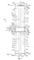
- the transport device 100 contains a stack 200 of pattern 201, to hold the stack 200 of pattern 201 in position.
- the patterns 201 have at least one branch 202 passing between the two extensions 117 side of the two uprights 104 located on the same side, the branch 202 maintains the lateral extensions 117 in an open position to the outside, which provides rigidity to the transport device 100, and the branch 202 is also maintained by these lateral extensions 117, between them, to have a minimum of movement latitude.
- the fold lines 115a, 115b and 110a, 110b respectively connecting the uprights 104 to the bottom 103 on the one hand and to the top panel 107 on the other hand extend parallel to each other. other.
- the fold lines 115a, 115b and 110a, 110b connecting the uprights 104 to the bottom 103 on the one hand and to the top panel 107 on the other hand extend perpendicular to the fold lines 116 forming the side of the uprights 104 bordered by the lateral extension 117.
- the transport device 100 has a parallelepiped shape adapted to receive a stack 200 of patterns 201.
- a generally cruciform configuration patterns 201 is particularly interesting for immobilization patterns in the transport device 100, as illustrated by the figure 2 for example.
- the uprights 104 located on two different sides of the bottom 103 face each other.
- the uprights 104 are each connected to the bottom 103, of a generally rectangular shape, from a longitudinal edge 119a, 119b thereof. This brings in particular a better stability to the transport device 100 when it is put in a supine position, for example on a feeder 300 of a machine, as illustrated by figure 3 .
- the blank 101 may have at least one precut line 120 to facilitate the opening of the transport device 100, and for convenience the precut line 120 is located on the bottom 103.
- the bottom 103 has four precut lines 120 which each bypass an amount 104 for separating each amount 104 individually from the others.
- each precut line 120 connects a longitudinal edge 119a, 119b to a lateral edge 121.
- each precut line 120 opens, at a longitudinal edge 119a, 119b, beyond the lateral extension 117 of each amount 104.
- the blank 101 of the figure 1 has a notch 126 on an upright 104, located on an outer side 124 of the upright 104.
- a notch allows for example to extract more easily the blank 101 from the rest of the strip of material in which it was formed.
- Such a notch 126 also serves as a key during the introduction of the patterns 201, so that the opening of the transport device 100 on the feeder 300 is oriented in the required direction.
- the figure 2 presents an embodiment of a transport device 100, for example put in volume from a blank 101 as represented on the figure 1 .
- It also has two pairs of uprights 104, a pair of uprights 104 comprising two uprights 104 located along the same edge of the bottom 103, which is, as previously described a longitudinal edge 119a, 119b.
- the two pairs of uprights 104 receive between them a stack 200 of patterns 201, which here have a cruciform shape.
- a first branch 202 passes between the uprights 104 of the same pair, by separating their lateral extensions 117.
- two other branches 203, 204 forming a cross of the bosses 201 open on both sides out of the transport device 100.
- the transport device 100 can receive a large number of pattern 201 of different shapes and sizes. To a certain extent, the dimensions of the different branches do not influence the design of the transport device 100.
- the Figures 3 to 5 illustrate a method of feeding a feeder 300 in patterns 201 for the constitution of packaging.
- the figure 3 illustrates a first step of depositing a transport device 100 of a stack 200 of patterns 201 for the constitution of coated packaging in the feeder 300.
- the bottom 103 of the transport device 100 is generally rectangular and comprises two precut lines 120 forming two non-parallel sides of a trapezium whose bases 127, 128 are merged with the fold lines 115a, 115b connecting the bottom 103 to the amounts 104.
- each precut line 120 runs towards the center of a longitudinal edge 119b on the one hand, and towards a corner 105 of the bottom 103 on the other hand, opposite the longitudinal edge 119b.
- each precut line 120 passes towards the center of a longitudinal edge 119b on the one hand, and on one edge on the other hand 121, or on a first longitudinal edge 119b beyond an inner side of each upright 104 on the one hand, and on the other hand beyond an outer side 124 of each upright 104 the other longitudinal edge 119a, towards a corner 105 of the bottom 103 for example, in a case where the uprights 104 would be distant from the side edges 121 of the bottom 103.
- the two precut lines 120 opening on the same longitudinal edge 119b, between two uprights 104, here have, between them, a protuberance forming a tongue 125 to facilitate their tearing to open the bottom 103.
- the Figures 4a and 4b illustrate a second step of the method of opening the transport device 100 to separate at least two amounts from each other.
- the transport devices 100 have four uprights 104 connected in pairs to the longitudinal edges 119a, 119b of the bottom 103.
- the opening of the transport device 100 thus makes it possible to separate two uprights 104 of the same longitudinal edge 119a, 119b of the two others.
- the figure 4a presents the transport device 100 of the figure 3 .
- the figure 4b presents another embodiment of a transport device 100, in which the bottom 103 has two parts 103a and 103b, the first part 103a covering the second part 103b, and reversible connection means 129, 130 intervening between these parts.
- the reversible connecting means 129, 130 are in the form of self-gripping connection means, such as loops and hooks.
- a first portion 103a comprises loops 129 and a second portion 103b includes hooks 130.
- the reverse is of course conceivable.
- Such a transport device 100 is for example formed from two blanks. It could, however, be formed of a single blank with, for example, a vertex panel 107 in one piece.
- Such an embodiment is particularly suitable for transport devices 100 reusable, for example plastic.
- the first part 103a is here of generally rectangular shape and is connected to two uprights 104 of a pair, while the second part 103b is formed by two tabs connected to the two other uprights 104 of the other pair. And more specifically, each leg of the second portion 103b is here connected to a single amount 104.
- the figure 5 illustrates a third step of the method of sliding the stack 200 of patterns 201 relative to the transport device 100 along the feeder 300, then remove the transport device 100.
- the transport device 100 shown is that of the figure 4a however, that of the figure 4b , or a transport device 100 resulting from the setting volume of a blank 101 as shown figure 1 would also be appropriate.
- a precut line 120 separates opposite posts 104, and is more convenient than a rotation around the various fold lines 115a. 115b, 110a, 110b or 109a, 109b where appropriate, can be realized.
- the spacing of two opposite uprights 104 makes it possible to slide the pile 200 of patterns 201 between them. This is particularly convenient when the transport device 100 is lying on a feeder 300 in order to be able to load the patterns 201 easily and quickly.
- a piece 103c which remains connected to a post 104 after tearing of the bottom 103 remains in an extension of the amount 104, that is to say has the same width, so as not to hinder the sliding of the stack 200.
- the pieces 103c of the figure 4a are particularly appropriate, while those of the figure 1 would be less. It would then be possible to remedy it if the precut line 120 debouched on the longitudinal edge 119a, 119b coinciding with the root 122 on the inner side of a corresponding upright 104.
- the transport device 100 can easily be removed, then discarded and recycled, or stored somewhere for later reuse.
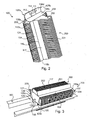
- figure 6 represents a pallet box 400, composed of a box 401 on a pallet 402, in which is disposed a plurality of transport devices 100 according to one of the embodiments described above, and each loaded with a stack 200 of patterns 201.
- the transport devices 100 are arranged nested so as to have a compact stack.
- the transport devices 100 could be arranged in staggered rows.
- the rigidity of the transport devices 100 in particular conferred by the presence of lateral extensions 117, allows stacking on two levels, or even several levels.
- a transport device 100 of a first level is separated from a transport device 100 of a second level by a sheet, for example made of corrugated cardboard, which gives them a better stability in the pallet box 400.
- the pallet box 400 has a flap or a workable panel 403, in particular to facilitate access to transport devices 100 of a lower level.
Landscapes
- Engineering & Computer Science (AREA)
- Mechanical Engineering (AREA)
- Making Paper Articles (AREA)
- Packaging Of Machine Parts And Wound Products (AREA)
Claims (18)
- Transportvorrichtung (100) zum Transportieren eines Stapels (200) von Schnittbögen (201), die zum Bilden von Verpackungen bestimmt sind, welche Vorrichtung ihrerseits durch Aufstellen zumindest eines Zuschnitts (101) aus Blattmaterial entsteht und dadurch gekennzeichnet ist, dass sie einen Boden (103) und zumindest zwei Stützen (104) aufweist, um zwischen diesen den Stapel (200) von Schnittbögen (201) von dem Boden (103) bis zu einer Scheitelwand (107) aufzunehmen, wobei jede Stütze (104) in Form eines Streifens aus dem genannten Material vorliegt, der von dem Boden (103) bis zur Scheitelwand (108) aufgerichtet ist, die als Verbindung der Stützen (104) dient, und dass jede Stütze (104) über eine Knicklinie (115a, 115b, 110a 110b) mit dem Boden (103) und mit der Scheitelwand (107) verbunden ist und über eine ihrer von der Knicklinie (116) gebildeten Seiten hinaus von einer seitlichen Verlängerung (117) gesäumt ist, die nach außerhalb der Transportvorrichtung (100) umgeknickt ist und sich vom Boden (103) bis zur Scheitelwand (107) erstreckt.
- Transportvorrichtung (100) nach Anspruch 1, dadurch gekennzeichnet, dass die Knicklinien (115a, 115b, 110a, 110b), die die Stützen (104) mit dem Boden (103) einerseits und mit der Scheitelwand (107) andererseits verbinden, sich parallel zueinander erstrecken und dass die Knicklinien (115a, 115b, 110a, 110b), die die Stützen (104) mit dem Boden (103) einerseits und mit der Scheitelwand (107) andererseits verbinden, sich senkrecht zu den Knicklinien (116) erstrecken, welche eine Seite der Stützen (104) bilden, die von einer seitlichen Verlängerung (117) umgeben ist.
- Transportvorrichtung (100) nach einem der Ansprüche 1 und 2, dadurch gekennzeichnet, dass die Schnittbögen (201), die zum Bilden von Verpackungen bestimmt und dazu vorgesehen sind, in die Transportvorrichtung (100) eingefügt zu werden, jeweils eine insgesamt kreuzförmige Gestalt haben.
- Transportvorrichtung (100) nach einem der Ansprüche 1 bis 3, dadurch gekennzeichnet, dass die Scheitelwand (107) sich in einem Stück zwischen den Stützen (104) erstreckt und zumindest einen Greifeinschnitt (112, 113) aufweist, der einen Griff (114) bildet.
- Transportvorrichtung (100) nach einem der Ansprüche 1 bis 3, dadurch gekennzeichnet, dass die Scheitelwand (107) zwei Abschnitte (107a, 107b) aufweist, die jeweils aus einem Bereich (108a, 108b) mit Hilfe einer Knicklinie (109a, 109b) gebildet sind, die sich parallel zu derjenigen (110a, 110b) erstreckt, welche die Scheitelwand (107) mit zumindest einer der Stützen (104) verbindet, so dass ein bezüglich der Verbindung der Scheitelwand (107) mit den Stützen (104) distaler Bereich (108c, 108d) eines Abschnitts (107a, 107b) der Scheitelwand (107) einen distalen Bereich (108c, 108d) des anderen Abschnitts (107a, 107b) der Scheitelwand (107) überdeckt, wobei Verriegelungsmittel (111, 112) zwischen den Abschnitten (107a, 107b) eingreifen, um sie aneinanderzuhalten, und dass die Verriegelungsmittel (111, 112) in Form einer Lasche (111) vorliegen, die aus einem Einschnitt (113) in einen der Abschnitte (107a, 107b) der Scheitelwand (107) stammt und dazu bestimmt ist, in einen Einschnitt (112) einzugreifen, der in dem anderen Abschnitt (107a, 107b) der Scheitelwand (107) ausgeführt ist, wobei die Abschnitte (107a, 107b) mit Hilfe ihrer Einschnitte (112, 113) einen Griff (114) bilden.
- Transportvorrichtung (100) nach einem der Ansprüche 4 oder 5, dadurch gekennzeichnet, dass der Griff (114) sich parallel zu den Knicklinien (110a, 110b) erstreckt, welche die Stützen (104) mit der Scheitelwand (107) verbinden.
- Transportvorrichtung (100) nach einem der Ansprüche 1 bis 6, dadurch gekennzeichnet, dass die Stützen (104) in einer Anzahl von vier vorliegen und paarweise beiderseits des Bodens (103) angeordnet sind, wobei die seitlichen Verlängerungen (117) zweier Stützen (104), die auf einer gleichen Seite angeordnet sind, einander zugewandt sind, und dass die seitlichen Verlängerungen (117) zweier Stützen (104), die auf einer gleichen Seite angeordnet und einander zugewandt sind, einen ausgesparten Durchgangsbereich (118) für den Durchtritt zumindest eines Schenkels (202) eines jeden der Schnittbögen (201) des Stapels (200) zwischen sich freilassen und dass die seitlichen Verlängerung (117) der beiden Stützen (104), die auf der gleichen Seite angeordnet und einander zugewandt sind, dazu ausgelegt sind, einen Rand des Schenkels (202) eines jeden der Schnittbögen (201) des Stapels (200) zwischen sich einzuklemmen, welcher Rand zwischen diesen durchtritt.
- Transportvorrichtung (100) nach Anspruch 7, dadurch gekennzeichnet, dass zwei der Stützen (104), die sich auf zwei verschiedenen Seiten des Bodens (103) befinden, einander gegenüberliegen und jeweils mit dem Boden (103) in im Allgemeinen rechteckiger Form ausgehend von einem Längsrand (119, 119b) desselben verbunden sind.
- Transportvorrichtung (100) nach einem der Ansprüche 1 bis 8, dadurch gekennzeichnet, dass der Boden (103) zumindest eine Perforationslinie (120) aufweist, über die es möglich ist, zumindest eine erste Stütze (104) von einer zweiten Stütze (104) über eines ihrer Enden abzutrennen.
- Transportvorrichtung (100) nach Anspruch 9, dadurch gekennzeichnet, dass der Boden (103) im Allgemeinen rechteckig ist und zwei Perforationslinien (120) aufweist, die zwei nicht parallele Seiten eines Trapezes bilden, dessen Grundseiten (127, 128) mit den Knicklinien (115a, 115b) zusammenfallen, welche dieses mit den Stützen (104) verbinden.
- Transportvorrichtung (100) nach einem der Ansprüche 1 bis 8, dadurch gekennzeichnet, dass der Boden (103) zwei Abschnitte (103a, 103b) und reversible Verbindungsmittel (129, 130) aufweist, die zwischen diese Abschnitte (103a, 103b) eingreifen.
- Transportvorrichtung (100) nach Anspruch 11, dadurch gekennzeichnet, dass die reversiblen Verbindungsmittel (129, 130) in Form von Klettverbindungsmittel vorliegen.
- Transportvorrichtung (100) nach Anspruch 11 oder 12, dadurch gekennzeichnet, dass ein erster Abschnitt (103a) im Allgemeinen in rechteckiger Form ist und über eine Knicklinie (115a) mit zumindest einer ersten Stütze (104) verbunden ist, während ein zweiter Abschnitt (103b) aus zumindest einer Lasche gebildet ist, die auch über eine Knicklinie (115b) mit einer zweiten Stütze (104) verbunden ist.
- Transportvorrichtung (100) nach einem der Ansprüche 1 bis 13, dadurch gekennzeichnet, dass das Blattmaterial des Zuschnitts (101) Karton oder Wellpappe ist.
- Transportvorrichtung (100) nach einem der Ansprüche 1 bis 13, dadurch gekennzeichnet, dass das Blattmaterial des Zuschnitts (101) ausgehend von einem halbstarren Kunststoffmaterial hergestellt ist.
- Palettenkiste (400), in welcher eine Mehrzahl von Transportvorrichtungen (100) nach einem der vorangehenden Ansprüche angeordnet ist, die jeweils mit einem Stapel (200) von Schnittbögen (201) beladen sind, wobei die Transportvorrichtungen (100) vorzugsweise überlappend angeordnet sind.
- Zuschnitt (101) für eine Transportvorrichtung (100) zum Transportieren eines Stapels (200) von Schnittbögen (201), die zum Bilden von Verpackungen bestimmt sind, dadurch gekennzeichnet, dass er aus einem geeignet zugeschnittenen und gefalzten Blattmaterial hergestellt ist, wobei der Zuschnitt (101) für die Herstellung einer Transportvorrichtung (100) zum Transportieren eines Stapels (200) von Schnittbögen (201) geeignet ist, die zum Bilden von Verpackungen nach einem der Ansprüche 1 bis 15 bestimmt sind.
- Verfahren zum Versorgen eines Anlegers (300) mit Schnittbögen (201), die zum Bilden von Verpackungen bestimmt sind, dadurch gekennzeichnet, dass es nachfolgende Schritte umfasst:- Einlegen einer Transportvorrichtung (100) zum Transportieren eines Stapels (200) von zum Bilden von Verpackungen bestimmten Schnittbögen (201) nach einem der Ansprüche 1 bis 17 liegend in den Anleger (300);- Öffnen der Transportvorrichtung (100), um zumindest zwei Stützen (104) voneinander zu trennen,- Verrücken des Stapels (200) von Schnittbögen (201) bezüglich der Transportvorrichtung (100) entlang des Anlegers (300) und Entfernen der Transportvorrichtung (100).
Applications Claiming Priority (1)
| Application Number | Priority Date | Filing Date | Title |
|---|---|---|---|
| FR1260671A FR2997929B1 (fr) | 2012-11-09 | 2012-11-09 | Dispositif de groupage et de transport d'une pile de patrons destines a la constitution d'emballages |
Publications (2)
| Publication Number | Publication Date |
|---|---|
| EP2730516A1 EP2730516A1 (de) | 2014-05-14 |
| EP2730516B1 true EP2730516B1 (de) | 2016-01-13 |
Family
ID=47624357
Family Applications (1)
| Application Number | Title | Priority Date | Filing Date |
|---|---|---|---|
| EP13189224.2A Active EP2730516B1 (de) | 2012-11-09 | 2013-10-18 | Vorrichtung zum Gruppieren und Transportieren einer Batterie von Hülsen, die für die Erstellung von Verpackungen bestimmt sind |
Country Status (3)
| Country | Link |
|---|---|
| EP (1) | EP2730516B1 (de) |
| ES (1) | ES2567331T3 (de) |
| FR (1) | FR2997929B1 (de) |
Family Cites Families (3)
| Publication number | Priority date | Publication date | Assignee | Title |
|---|---|---|---|---|
| US7021886B2 (en) * | 2002-04-12 | 2006-04-04 | Pitney Bowes Inc. | Paper supply system and cart for a high-speed sheet feeder |
| US8413809B2 (en) * | 2008-05-02 | 2013-04-09 | Certainteed Corporation | Packaging for specialty shingle |
| GB2483456A (en) * | 2010-09-08 | 2012-03-14 | Kcm Partnership | Packaging system for stacks of carton blanks |
-
2012
- 2012-11-09 FR FR1260671A patent/FR2997929B1/fr not_active Expired - Fee Related
-
2013
- 2013-10-18 ES ES13189224.2T patent/ES2567331T3/es active Active
- 2013-10-18 EP EP13189224.2A patent/EP2730516B1/de active Active
Also Published As
| Publication number | Publication date |
|---|---|
| FR2997929A1 (fr) | 2014-05-16 |
| ES2567331T3 (es) | 2016-04-21 |
| EP2730516A1 (de) | 2014-05-14 |
| FR2997929B1 (fr) | 2015-01-16 |
Similar Documents
| Publication | Publication Date | Title |
|---|---|---|
| EP1919782B1 (de) | Wellpappenschachtel mit durchbrochenen klappen und anordnung von zuschnitten, um diese zu erhalten | |
| EP3102494B1 (de) | Aus pappebahnmaterial hergestellte schale zur manuellen montage und rohling zur herstellung solch einer schale | |
| EP2730516B1 (de) | Vorrichtung zum Gruppieren und Transportieren einer Batterie von Hülsen, die für die Erstellung von Verpackungen bestimmt sind | |
| EP3243759B1 (de) | Paket, das einen gegenstand mit eingeschlossener korrosiver flüssigkeit umfasst | |
| EP0738664B1 (de) | Selbsttragende Verkaufsverpackung aus Pappe, insbesondere für thermogeformte Töpfe | |
| EP0765823A1 (de) | Behälter für Fahrräder | |
| EP3097021B1 (de) | In eine anzeige umwandelbarer transportbehälter | |
| EP0669257B1 (de) | Faltschachtel Karton oder dergleichen, insbesondere zur Aufnahme von Milchprodukt-Behältern, sowie Zuschnitt zu ihrer Herstellung | |
| WO2018078289A1 (fr) | Système de maintien d'une rangée de pots individualisés, kit de flans et conditionnement de pots individualisés | |
| FR3082510A1 (fr) | Emballage pour produit horticole | |
| FR2793472A1 (fr) | Conditionnement en deux parties emboitables l'une dans l'autre | |
| EP1120360B1 (de) | Schachtel mit zwei zu einander versetzten Ausgabeöffnungen | |
| EP2017182B1 (de) | Verpackung mit versenkbarem Griff | |
| BE1003769A3 (fr) | Boite en carton comportant une poignee. | |
| EP1088767A1 (de) | Ein voluminöses Material enthaltender Sack aus flexiblem Material und Säckestapel | |
| WO2018141837A1 (fr) | Decoupe plane pliable en carton et emballage pour fromage a la coupe realisé par pliage de ladite decoupe | |
| EP2956371B1 (de) | Keil zur immobilisierung von objekten in einer dose mit einem quadratischen oder rechteckigen querschnitt | |
| FR3135257A1 (fr) | Emballage transportable et superposable | |
| EP1795451B1 (de) | Behälter, insbesondere für Nahrungsmittel | |
| BE1001359A6 (fr) | Recipient empilable, flan pour la fabrication d'un tel recipient et presentoir forme de tels recipients empiles. | |
| FR3050180B1 (fr) | Element pour caisse en materiau semi-rigide pour ramettes de feuilles de papier | |
| EP2746179A1 (de) | Paarweise stapelbare Kartonsteigen | |
| FR3032945A1 (fr) | Feuille de carton formant couvercle de protection | |
| FR2969581A1 (fr) | Emballage en materiau semi-rigide | |
| FR2884808A1 (fr) | Conditionnement destine a regrouper une pluralite d'objets ou de produits individuellement separables. |
Legal Events
| Date | Code | Title | Description |
|---|---|---|---|
| PUAI | Public reference made under article 153(3) epc to a published international application that has entered the european phase |
Free format text: ORIGINAL CODE: 0009012 |
|
| 17P | Request for examination filed |
Effective date: 20131018 |
|
| AK | Designated contracting states |
Kind code of ref document: A1 Designated state(s): AL AT BE BG CH CY CZ DE DK EE ES FI FR GB GR HR HU IE IS IT LI LT LU LV MC MK MT NL NO PL PT RO RS SE SI SK SM TR |
|
| AX | Request for extension of the european patent |
Extension state: BA ME |
|
| R17P | Request for examination filed (corrected) |
Effective date: 20140924 |
|
| RBV | Designated contracting states (corrected) |
Designated state(s): AL AT BE BG CH CY CZ DE DK EE ES FI FR GB GR HR HU IE IS IT LI LT LU LV MC MK MT NL NO PL PT RO RS SE SI SK SM TR |
|
| RIC1 | Information provided on ipc code assigned before grant |
Ipc: B65D 85/62 20060101ALN20150428BHEP Ipc: B65D 71/22 20060101AFI20150428BHEP Ipc: B65H 1/02 20060101ALI20150428BHEP |
|
| GRAP | Despatch of communication of intention to grant a patent |
Free format text: ORIGINAL CODE: EPIDOSNIGR1 |
|
| GRAJ | Information related to disapproval of communication of intention to grant by the applicant or resumption of examination proceedings by the epo deleted |
Free format text: ORIGINAL CODE: EPIDOSDIGR1 |
|
| GRAP | Despatch of communication of intention to grant a patent |
Free format text: ORIGINAL CODE: EPIDOSNIGR1 |
|
| INTG | Intention to grant announced |
Effective date: 20150619 |
|
| INTG | Intention to grant announced |
Effective date: 20150629 |
|
| INTG | Intention to grant announced |
Effective date: 20150706 |
|
| GRAS | Grant fee paid |
Free format text: ORIGINAL CODE: EPIDOSNIGR3 |
|
| GRAA | (expected) grant |
Free format text: ORIGINAL CODE: 0009210 |
|
| AK | Designated contracting states |
Kind code of ref document: B1 Designated state(s): AL AT BE BG CH CY CZ DE DK EE ES FI FR GB GR HR HU IE IS IT LI LT LU LV MC MK MT NL NO PL PT RO RS SE SI SK SM TR |
|
| REG | Reference to a national code |
Ref country code: GB Ref legal event code: FG4D Free format text: NOT ENGLISH |
|
| REG | Reference to a national code |
Ref country code: CH Ref legal event code: EP |
|
| REG | Reference to a national code |
Ref country code: IE Ref legal event code: FG4D Free format text: LANGUAGE OF EP DOCUMENT: FRENCH |
|
| REG | Reference to a national code |
Ref country code: AT Ref legal event code: REF Ref document number: 770341 Country of ref document: AT Kind code of ref document: T Effective date: 20160215 |
|
| REG | Reference to a national code |
Ref country code: DE Ref legal event code: R096 Ref document number: 602013004605 Country of ref document: DE |
|
| REG | Reference to a national code |
Ref country code: ES Ref legal event code: FG2A Ref document number: 2567331 Country of ref document: ES Kind code of ref document: T3 Effective date: 20160421 |
|
| RAP2 | Party data changed (patent owner data changed or rights of a patent transferred) |
Owner name: DS SMITH PACKAGING CONSUMER |
|
| REG | Reference to a national code |
Ref country code: LT Ref legal event code: MG4D |
|
| REG | Reference to a national code |
Ref country code: NL Ref legal event code: MP Effective date: 20160113 |
|
| REG | Reference to a national code |
Ref country code: AT Ref legal event code: MK05 Ref document number: 770341 Country of ref document: AT Kind code of ref document: T Effective date: 20160113 |
|
| PG25 | Lapsed in a contracting state [announced via postgrant information from national office to epo] |
Ref country code: NL Free format text: LAPSE BECAUSE OF FAILURE TO SUBMIT A TRANSLATION OF THE DESCRIPTION OR TO PAY THE FEE WITHIN THE PRESCRIBED TIME-LIMIT Effective date: 20160113 |
|
| PG25 | Lapsed in a contracting state [announced via postgrant information from national office to epo] |
Ref country code: GR Free format text: LAPSE BECAUSE OF FAILURE TO SUBMIT A TRANSLATION OF THE DESCRIPTION OR TO PAY THE FEE WITHIN THE PRESCRIBED TIME-LIMIT Effective date: 20160414 Ref country code: FI Free format text: LAPSE BECAUSE OF FAILURE TO SUBMIT A TRANSLATION OF THE DESCRIPTION OR TO PAY THE FEE WITHIN THE PRESCRIBED TIME-LIMIT Effective date: 20160113 Ref country code: HR Free format text: LAPSE BECAUSE OF FAILURE TO SUBMIT A TRANSLATION OF THE DESCRIPTION OR TO PAY THE FEE WITHIN THE PRESCRIBED TIME-LIMIT Effective date: 20160113 Ref country code: NO Free format text: LAPSE BECAUSE OF FAILURE TO SUBMIT A TRANSLATION OF THE DESCRIPTION OR TO PAY THE FEE WITHIN THE PRESCRIBED TIME-LIMIT Effective date: 20160413 |
|
| REG | Reference to a national code |
Ref country code: FR Ref legal event code: PLFP Year of fee payment: 4 |
|
| PG25 | Lapsed in a contracting state [announced via postgrant information from national office to epo] |
Ref country code: LV Free format text: LAPSE BECAUSE OF FAILURE TO SUBMIT A TRANSLATION OF THE DESCRIPTION OR TO PAY THE FEE WITHIN THE PRESCRIBED TIME-LIMIT Effective date: 20160113 Ref country code: RS Free format text: LAPSE BECAUSE OF FAILURE TO SUBMIT A TRANSLATION OF THE DESCRIPTION OR TO PAY THE FEE WITHIN THE PRESCRIBED TIME-LIMIT Effective date: 20160113 Ref country code: SE Free format text: LAPSE BECAUSE OF FAILURE TO SUBMIT A TRANSLATION OF THE DESCRIPTION OR TO PAY THE FEE WITHIN THE PRESCRIBED TIME-LIMIT Effective date: 20160113 Ref country code: LT Free format text: LAPSE BECAUSE OF FAILURE TO SUBMIT A TRANSLATION OF THE DESCRIPTION OR TO PAY THE FEE WITHIN THE PRESCRIBED TIME-LIMIT Effective date: 20160113 Ref country code: PT Free format text: LAPSE BECAUSE OF FAILURE TO SUBMIT A TRANSLATION OF THE DESCRIPTION OR TO PAY THE FEE WITHIN THE PRESCRIBED TIME-LIMIT Effective date: 20160513 Ref country code: IS Free format text: LAPSE BECAUSE OF FAILURE TO SUBMIT A TRANSLATION OF THE DESCRIPTION OR TO PAY THE FEE WITHIN THE PRESCRIBED TIME-LIMIT Effective date: 20160513 Ref country code: AT Free format text: LAPSE BECAUSE OF FAILURE TO SUBMIT A TRANSLATION OF THE DESCRIPTION OR TO PAY THE FEE WITHIN THE PRESCRIBED TIME-LIMIT Effective date: 20160113 Ref country code: PL Free format text: LAPSE BECAUSE OF FAILURE TO SUBMIT A TRANSLATION OF THE DESCRIPTION OR TO PAY THE FEE WITHIN THE PRESCRIBED TIME-LIMIT Effective date: 20160113 |
|
| REG | Reference to a national code |
Ref country code: DE Ref legal event code: R097 Ref document number: 602013004605 Country of ref document: DE |
|
| PG25 | Lapsed in a contracting state [announced via postgrant information from national office to epo] |
Ref country code: DK Free format text: LAPSE BECAUSE OF FAILURE TO SUBMIT A TRANSLATION OF THE DESCRIPTION OR TO PAY THE FEE WITHIN THE PRESCRIBED TIME-LIMIT Effective date: 20160113 Ref country code: EE Free format text: LAPSE BECAUSE OF FAILURE TO SUBMIT A TRANSLATION OF THE DESCRIPTION OR TO PAY THE FEE WITHIN THE PRESCRIBED TIME-LIMIT Effective date: 20160113 |
|
| PLBE | No opposition filed within time limit |
Free format text: ORIGINAL CODE: 0009261 |
|
| STAA | Information on the status of an ep patent application or granted ep patent |
Free format text: STATUS: NO OPPOSITION FILED WITHIN TIME LIMIT |
|
| PG25 | Lapsed in a contracting state [announced via postgrant information from national office to epo] |
Ref country code: SK Free format text: LAPSE BECAUSE OF FAILURE TO SUBMIT A TRANSLATION OF THE DESCRIPTION OR TO PAY THE FEE WITHIN THE PRESCRIBED TIME-LIMIT Effective date: 20160113 Ref country code: SM Free format text: LAPSE BECAUSE OF FAILURE TO SUBMIT A TRANSLATION OF THE DESCRIPTION OR TO PAY THE FEE WITHIN THE PRESCRIBED TIME-LIMIT Effective date: 20160113 Ref country code: CZ Free format text: LAPSE BECAUSE OF FAILURE TO SUBMIT A TRANSLATION OF THE DESCRIPTION OR TO PAY THE FEE WITHIN THE PRESCRIBED TIME-LIMIT Effective date: 20160113 Ref country code: RO Free format text: LAPSE BECAUSE OF FAILURE TO SUBMIT A TRANSLATION OF THE DESCRIPTION OR TO PAY THE FEE WITHIN THE PRESCRIBED TIME-LIMIT Effective date: 20160113 |
|
| 26N | No opposition filed |
Effective date: 20161014 |
|
| PG25 | Lapsed in a contracting state [announced via postgrant information from national office to epo] |
Ref country code: BG Free format text: LAPSE BECAUSE OF FAILURE TO SUBMIT A TRANSLATION OF THE DESCRIPTION OR TO PAY THE FEE WITHIN THE PRESCRIBED TIME-LIMIT Effective date: 20160413 Ref country code: SI Free format text: LAPSE BECAUSE OF FAILURE TO SUBMIT A TRANSLATION OF THE DESCRIPTION OR TO PAY THE FEE WITHIN THE PRESCRIBED TIME-LIMIT Effective date: 20160113 Ref country code: BE Free format text: LAPSE BECAUSE OF NON-PAYMENT OF DUE FEES Effective date: 20161031 |
|
| REG | Reference to a national code |
Ref country code: CH Ref legal event code: PL |
|
| REG | Reference to a national code |
Ref country code: FR Ref legal event code: PLFP Year of fee payment: 5 |
|
| REG | Reference to a national code |
Ref country code: IE Ref legal event code: MM4A |
|
| PG25 | Lapsed in a contracting state [announced via postgrant information from national office to epo] |
Ref country code: LI Free format text: LAPSE BECAUSE OF NON-PAYMENT OF DUE FEES Effective date: 20161031 Ref country code: CH Free format text: LAPSE BECAUSE OF NON-PAYMENT OF DUE FEES Effective date: 20161031 |
|
| PG25 | Lapsed in a contracting state [announced via postgrant information from national office to epo] |
Ref country code: LU Free format text: LAPSE BECAUSE OF NON-PAYMENT OF DUE FEES Effective date: 20161018 |
|
| PG25 | Lapsed in a contracting state [announced via postgrant information from national office to epo] |
Ref country code: IE Free format text: LAPSE BECAUSE OF NON-PAYMENT OF DUE FEES Effective date: 20161018 |
|
| REG | Reference to a national code |
Ref country code: BE Ref legal event code: MM Effective date: 20161031 |
|
| PG25 | Lapsed in a contracting state [announced via postgrant information from national office to epo] |
Ref country code: CY Free format text: LAPSE BECAUSE OF FAILURE TO SUBMIT A TRANSLATION OF THE DESCRIPTION OR TO PAY THE FEE WITHIN THE PRESCRIBED TIME-LIMIT Effective date: 20160113 Ref country code: HU Free format text: LAPSE BECAUSE OF FAILURE TO SUBMIT A TRANSLATION OF THE DESCRIPTION OR TO PAY THE FEE WITHIN THE PRESCRIBED TIME-LIMIT; INVALID AB INITIO Effective date: 20131018 |
|
| PG25 | Lapsed in a contracting state [announced via postgrant information from national office to epo] |
Ref country code: MT Free format text: LAPSE BECAUSE OF FAILURE TO SUBMIT A TRANSLATION OF THE DESCRIPTION OR TO PAY THE FEE WITHIN THE PRESCRIBED TIME-LIMIT Effective date: 20160113 Ref country code: MK Free format text: LAPSE BECAUSE OF FAILURE TO SUBMIT A TRANSLATION OF THE DESCRIPTION OR TO PAY THE FEE WITHIN THE PRESCRIBED TIME-LIMIT Effective date: 20160113 Ref country code: MC Free format text: LAPSE BECAUSE OF FAILURE TO SUBMIT A TRANSLATION OF THE DESCRIPTION OR TO PAY THE FEE WITHIN THE PRESCRIBED TIME-LIMIT Effective date: 20160113 |
|
| REG | Reference to a national code |
Ref country code: FR Ref legal event code: PLFP Year of fee payment: 6 |
|
| PG25 | Lapsed in a contracting state [announced via postgrant information from national office to epo] |
Ref country code: TR Free format text: LAPSE BECAUSE OF FAILURE TO SUBMIT A TRANSLATION OF THE DESCRIPTION OR TO PAY THE FEE WITHIN THE PRESCRIBED TIME-LIMIT Effective date: 20160113 Ref country code: AL Free format text: LAPSE BECAUSE OF FAILURE TO SUBMIT A TRANSLATION OF THE DESCRIPTION OR TO PAY THE FEE WITHIN THE PRESCRIBED TIME-LIMIT Effective date: 20160113 |
|
| P01 | Opt-out of the competence of the unified patent court (upc) registered |
Effective date: 20230529 |
|
| PGFP | Annual fee paid to national office [announced via postgrant information from national office to epo] |
Ref country code: IT Payment date: 20250806 Year of fee payment: 13 |
|
| PGFP | Annual fee paid to national office [announced via postgrant information from national office to epo] |
Ref country code: FR Payment date: 20250930 Year of fee payment: 13 |
|
| PGFP | Annual fee paid to national office [announced via postgrant information from national office to epo] |
Ref country code: DE Payment date: 20251027 Year of fee payment: 13 |
|
| PGFP | Annual fee paid to national office [announced via postgrant information from national office to epo] |
Ref country code: GB Payment date: 20251022 Year of fee payment: 13 |
|
| PGFP | Annual fee paid to national office [announced via postgrant information from national office to epo] |
Ref country code: ES Payment date: 20251103 Year of fee payment: 13 |