EP2729261B1 - Siebrahmen für ultraschallsieb und ultraschallsieb - Google Patents
Siebrahmen für ultraschallsieb und ultraschallsieb Download PDFInfo
- Publication number
- EP2729261B1 EP2729261B1 EP12775606.2A EP12775606A EP2729261B1 EP 2729261 B1 EP2729261 B1 EP 2729261B1 EP 12775606 A EP12775606 A EP 12775606A EP 2729261 B1 EP2729261 B1 EP 2729261B1
- Authority
- EP
- European Patent Office
- Prior art keywords
- sieve
- frame
- sieve frame
- groove
- opening
- Prior art date
- Legal status (The legal status is an assumption and is not a legal conclusion. Google has not performed a legal analysis and makes no representation as to the accuracy of the status listed.)
- Active
Links
Images

Classifications
-
- B—PERFORMING OPERATIONS; TRANSPORTING
- B07—SEPARATING SOLIDS FROM SOLIDS; SORTING
- B07B—SEPARATING SOLIDS FROM SOLIDS BY SIEVING, SCREENING, SIFTING OR BY USING GAS CURRENTS; SEPARATING BY OTHER DRY METHODS APPLICABLE TO BULK MATERIAL, e.g. LOOSE ARTICLES FIT TO BE HANDLED LIKE BULK MATERIAL
- B07B1/00—Sieving, screening, sifting, or sorting solid materials using networks, gratings, grids, or the like
- B07B1/42—Drive mechanisms, regulating or controlling devices, or balancing devices, specially adapted for screens
-
- B—PERFORMING OPERATIONS; TRANSPORTING
- B07—SEPARATING SOLIDS FROM SOLIDS; SORTING
- B07B—SEPARATING SOLIDS FROM SOLIDS BY SIEVING, SCREENING, SIFTING OR BY USING GAS CURRENTS; SEPARATING BY OTHER DRY METHODS APPLICABLE TO BULK MATERIAL, e.g. LOOSE ARTICLES FIT TO BE HANDLED LIKE BULK MATERIAL
- B07B1/00—Sieving, screening, sifting, or sorting solid materials using networks, gratings, grids, or the like
- B07B1/06—Cone or disc shaped screens
-
- B—PERFORMING OPERATIONS; TRANSPORTING
- B07—SEPARATING SOLIDS FROM SOLIDS; SORTING
- B07B—SEPARATING SOLIDS FROM SOLIDS BY SIEVING, SCREENING, SIFTING OR BY USING GAS CURRENTS; SEPARATING BY OTHER DRY METHODS APPLICABLE TO BULK MATERIAL, e.g. LOOSE ARTICLES FIT TO BE HANDLED LIKE BULK MATERIAL
- B07B1/00—Sieving, screening, sifting, or sorting solid materials using networks, gratings, grids, or the like
- B07B1/46—Constructional details of screens in general; Cleaning or heating of screens
-
- B—PERFORMING OPERATIONS; TRANSPORTING
- B07—SEPARATING SOLIDS FROM SOLIDS; SORTING
- B07B—SEPARATING SOLIDS FROM SOLIDS BY SIEVING, SCREENING, SIFTING OR BY USING GAS CURRENTS; SEPARATING BY OTHER DRY METHODS APPLICABLE TO BULK MATERIAL, e.g. LOOSE ARTICLES FIT TO BE HANDLED LIKE BULK MATERIAL
- B07B2230/00—Specific aspects relating to the whole B07B subclass
- B07B2230/04—The screen or the screened materials being subjected to ultrasonic vibration
Definitions
- the invention relates to a sieve frame for an ultrasonic sieve with the features of the preamble of claim 1 protection and an ultrasonic sieve with the features of the preamble of claim 5 protection.
- the desire is naturally directed to a given screening machine after the shortest possible changeover and cleaning time for different screenings, e.g. Color powder of different colors to use.
- the tissue sound conductor represents an additional structure in the powder flow, which has niches, corners and edges and thus makes it difficult to clean the ultrasound sieve.
- the DE 10 2006 047 592 A1 , the DE 20 2006 009 068 U1 and the JP 2007 130 520 A each disclose a screen frame for an ultrasonic sieve with an upper surface for attachment of a sieve fabric, an underside opposite the upper side and an opening enclosed by the sieve frame, wherein a tissue sound conductor covers at least partially coupled from the rest of the sieve frame in the inner part of the sieve frame and the sieve Ultrasound is arranged.
- the sieve frame for an ultrasonic sieve has an upper side for attachment of a sieve fabric, an underside opposite the upper side and an opening enclosed by the sieve frame, through which the sieve material, when the sieve - e.g. is used in a screening machine, flows through it.
- the respective size is always in the direction of direct Way between the top and bottom of the screen frame to measure.
- the sieve frame has at least one groove running around the opening, so that the part of the sieve frame lying between the edge of the groove facing the opening and the opening forms a tissue sound conductor, which with respect to the transmission of ultrasound from one through the unmodified remainder of the screen frame formed outer screen frame is at least partially decoupled.
- This partial decoupling with regard to the transmission of ultrasound ensures that the remaining part of the sieve frame is at most weakly excited even with an ultrasound excitation of the part of the sieve frame forming the tissue sound conductor, which is necessary to effect the desired ultrasound excitation of the sieve tissue.
- this remaining part of the screen frame is the one to which the sealing elements abut when installed in the screening machine, the unwanted excitation of the sealing elements and the resulting generation of heat in the system is largely avoided.
- groove is to be interpreted broadly and functionally.
- the partial decoupling follows from the fact that when providing a circumferential groove in the sense of a depression or recess in the screen frame, the beginning and end of which merge into each other, in the region of the screen frame in which the groove is arranged, ultrasound only on the complementary to the groove Bridge can be transferred.
- “Complementary” means that the thickness of the web and the depth of the groove, measured respectively in the direction from the top of the screen frame to the bottom, together the thickness of the screen frame at a location where no groove is arranged, give.
- a groove in the sense of this patent application is present both when the depression was produced by removing material of the screen frame, as well as when the screen frame of a first, the tissue sound conductor forming part, an outer frame and between the tissue sound conductor and the arranged outside and attached to these or connected thereto web with a thickness which is smaller than the thickness of tissue sound conductor and outer frame composed.
- the use of the term "web” is not intended to imply that the web extending between the fabric sound conductor and the outer frame must have an edge in a direction laterally to its direction, in particular the complement to a circumferential groove whose beginning and end coincide, also from Bridge called.
- a sieve frame comprising an outer sieve frame, which is connected to a fabric sound conductor only via individual struts, between which a material passage from the Top to bottom of the screen frame is possible, not the invention.
- the groove is arranged on the upper side of the screen frame.
- the top of the screen frame is, as already defined above, the side of the screen frame over which the screen cloth is pulled.
- an adhesive layer covering the groove so that material to be screened from either side of the groove can not penetrate therein, which significantly simplifies the cleaning of the mesh frame.
- the ultrasonic sieve according to the invention has a sieve frame, a screen fabric stretched on the sieve frame, a tissue sound conductor for introducing ultrasound into the screen fabric stretched on the screen frame, an ultrasound converter for generating ultrasound and a feed sound conductor for supplying the ultrasound generated by the ultrasound converter to the tissue sound conductor.
- the sieve frame has at least one upper side, to which the sieve cloth is fastened, an underside opposite the upper side and an opening enclosed by the sieve frame, through which the sieve material can flow as it passes through the sieve cloth.
- the sieve frame has at least one groove running around the opening, so that the part of the sieve frame lying between the edge of the groove facing the opening and the opening forms a tissue sound conductor which is unmodified with respect to the transmission of ultrasound Rest formed of the screen frame outer screen frame of the screen frame is at least partially decoupled.
- the tissue sound conductor is a section of the screen frame, which is guided around an opening enclosed by the screen frame and arranged in the screen frame, which is at least partially decoupled from the rest of the screen frame with regard to the transmission of ultrasound.
- the sieve cloth is fastened to the sieve frame with an adhesive layer and the adhesive layer extends over the groove so that the groove or its opening in the direction of the upper side of the sieve frame is closed by the adhesive layer.
- the adhesive layer extends over the groove so that the groove or its opening in the direction of the upper side of the sieve frame is closed by the adhesive layer.
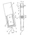
- FIG. 1a shows a top view obliquely from above on an ultrasonic sieve 10 with a sieve frame 1, which defines an opening 20 and with a arranged on top of the sieve frame screen fabric 6. Furthermore, one recognizes an ultrasonic converter 5 for generating ultrasound and a feed sound conductor 4. Like the ultrasound is introduced from the ultrasonic converter 5 using the feed sound conductor 4 in the screen fabric 6, will be explained in detail below.
- FIG. 1a Sieve frame 1 shown particularly well in the cross-sectional view of FIG. 1b explain. Since it is a cross section through a symmetrically constructed structure, only the right side of the figure has been provided with reference numerals, but the left side of Figure 1b is constructed identically from outside to inside as the right side viewed from outside to inside.
- This figure shows that the screen frame 1 has a groove 9 whose bottom is formed by a web 2, which for better illustration or emphasis in FIG. 1b is shown as a bold line.
- This groove 9 divides the sieve frame 1 into a tissue sound conductor 3 which passes through the region of the sieve frame 1 which faces the edge 8 of the sieve frame 1 facing the opening 20 and the opening 20 facing the opening 20 (ie, the opening 20 closer) 9 and an outer screen frame 23 formed by the unmodified remainder of the screen frame 1.
- FIG. 1b it can be seen that the screen fabric 6 is pulled to the side facing away from the opening 20 edge 7 of the screen frame 1 and further in the area between the opening 20 facing edge 8 of the screen frame 1 and the side facing away from the opening 20 edge 7 of the screen frame 1 with FIG. 1b shown as a dotted line an adhesive layer 21 is attached to the screen frame 1.
- the adhesive layer 21 advantageously also covers the groove 9, so that the groove 9 is protected on all sides against the ingress of screenings.
- the feed sound conductor 4 is expediently passed through the outer screen frame 23 in such a way that it does not transmit any vibrations to this part of the screen frame, so that only a direct excitation of the part of the screen frame 1 forming the tissue sound conductor 3 takes place.
- This can be achieved in a particularly advantageous manner, when the feed sound conductor 4 is passed through a hole in the outer screen frame 23, and the area of this passage is sealed by the sealant with a hole, because so the penetration of powder is effectively prevented, although a extensive vibrational decoupling between Feed sound conductor 4 and outer screen frame 23 consists.
- the tissue sound conductor 3 then initiates the ultrasound into the mesh screen 6.
- the concrete dimensioning of web 2 or the groove 9 complementary to this depends on the material and geometry of the screen frame 1, but it has proved to be particularly expedient to set a web thickness of 1 mm.
- FIGS. 2a and 2b Shown embodiment of an ultrasonic sieve 50 with screen frame 51, web 52, fabric sound conductor 53, feed sound conductor 54, ultrasonic converter 55, screen fabric 56, opening 60, remote from the opening edge 57, the opening facing edge 58, groove 59, adhesive layer 61, the opening facing edge
- the groove 62 and the rest or outer part of the screen frame 63 differs only in the geometric shape of the screen frame 51, which is rectangular. Basically, the screen geometry is limited only by the requirements of the application.
Landscapes
- Combined Means For Separation Of Solids (AREA)
Description
- Die Erfindung betrifft einen Siebrahmen für ein Ultraschallsieb mit den Merkmalen des Oberbegriffs des Schutzanspruchs 1 und ein Ultraschallsieb mit den Merkmalen des Oberbegriffs des Schutzanspruchs 5.
- Beim Ultraschallsieben insbesondere von Kunststoffpulvern im Pulverbeschichtungsprozess gibt es zwei wesentliche Probleme:
- Einerseits ist es essentiell, eine Erwärmung des zu siebenden Materials zu vermeiden. Eine derartige Erwärmung führt dazu, dass das Pulver weich wird und trotz der den Pulverdurchsatz unterstützenden Wirkung des Ultraschalls die Löcher des Siebgewebes verschließt, so dass der Siebprozess sukzessive zum Erliegen kommt.
- Untersucht man die Ursachen einer möglichen Erwärmung stellt man fest, dass diese besonders häufig dann auftritt, wenn der Ultraschall durch eine Ultraschallanregung des Siebrahmens auf das Siebgewebe übertragen wird. Der Grund hierfür liegt darin, dass der Siebrahmen in der Siebmaschine abgedichtet angeordnet werden muss, da sonst nicht gesiebtes Pulver am Sieb vorbei gelangen könnte. Somit kommt es zur Ultraschallanregung von unter Druck stehenden Abdichtelementen über den Rahmen, die fast vollständig in Wärme umgesetzt und dann über den Siebrahmen abgeführt wird. Dementsprechend wird der Siebrahmen warm und beheizt dann auch das Siebgewebe und das mit diesem wechselwirkende, zu siebende Material.
- Aus dem Stand der Technik ist es bekannt, eine solche Erwärmung dadurch zu vermeiden, dass die Anregung nicht über den Siebrahmen selbst erfolgt, sondern stattdessen der Ultraschall unter Vermeidung einer Anregung über den Siebrahmen über auf dem Siebgewebe angeordnete, separate Gewebeschallleiter in das Siebgewebe eingeleitet wird.
- Andererseits ist naturgemäß das Bestreben darauf gerichtet, eine gegebene Siebmaschine nach möglichst kurzer Umrüst- und Reinigungszeit für unterschiedliche Siebgüter, z.B. Farbpulver unterschiedlicher Farben, nutzen zu können. In der Praxis zeigt sich, dass der Gewebeschallleiter eine zusätzliche Struktur im Pulverfluss darstellt, die Nischen, Ecken und Kanten besitzt und dadurch die Reinigung des Ultraschallsiebes erschwert.
- Die
DE 10 2006 047 592 A1 , dieDE 20 2006 009 068 U1 und dieJP 2007 130 520 A - Aus der
US 3,792,774 A1 ist ein Siebrahmen mit einer darin angeordneten Nut bekannt, mit der die Siebspannung eingestellt werden kann. - Es stellt sich daher die Aufgabe, einen Siebrahmen für ein Ultraschallsieb und ein Ultraschallsieb bereitzustellen, bei dem einerseits eine Erwärmung des Siebgewebes weitestgehend vermieden wird, ohne dass ein erhöhter Reinigungsaufwand erforderlich ist.
- Diese Aufgabe wird gelöst durch einen Siebrahmen für ein Ultraschallsieb mit den Merkmalen des Schutzanspruchs 1 und durch ein Ultraschallsieb mit den Merkmalen des Schutzanspruchs 5. Vorteilhafte Ausgestaltungen der Erfindung sind Gegenstand der jeweiligen Unteransprüche.
- Der erfindungsgemäße Siebrahmen für ein Ultraschallsieb hat eine Oberseite zur Befestigung eines Siebgewebes, eine der O-berseite gegenüberliegenden Unterseite und eine vom Siebrahmen umschlossene Öffnung, durch die das Siebgut, wenn das Sieb - z.B. in einer Siebmaschine- verwendet wird, hindurchfließt.
- Wenn nachfolgend von der Begriff "Dicke" oder "Tiefe" verwendet wird, ist die jeweilige Größe stets in Richtung des direkten Wegs zwischen Ober- und Unterseite des Siebrahmens zu messen.
- Erfindungswesentlich ist, dass der Siebrahmen mindestens eine um die Öffnung herum laufende Nut aufweist, so dass der zwischen dem der Öffnung zugewandten Rand der Nut und der Öffnung liegende Teil des Siebrahmens einen Gewebeschallleiter bildet, der im Hinblick auf die Übertragung von Ultraschall von einem durch den unmodifizierten Rest des Siebrahmens gebildeten äußeren Siebrahmen zumindest partiell entkoppelt ist.
- Durch diese partielle Entkopplung im Hinblick auf die Übertragung von Ultraschall wird sichergestellt, dass auch bei einer Ultraschallanregung des den Gewebeschallleiter bildenden Teils des Siebrahmens, die notwendig ist, um die gewünschte Ultraschallanregung des Siebgewebes zu bewirken, der verbleibende Teil des Siebrahmens allenfalls schwach angeregt wird. Da dieser verbleibende Teil des Siebrahmens aber derjenige ist, an dem im in die Siebmaschine eingebauten Zustand die Dichtungselemente anliegen, wird die unerwünschte Anregung der Dichtungselemente und die daraus resultierende Erzeugung von Wärme im System weitgehend vermieden.
- Der Begriff "Nut" ist dabei breit und funktionell auszulegen. Die partielle Entkopplung folgt daraus, dass beim Vorsehen einer umlaufenden Nut im Sinne einer Vertiefung oder Ausnehmung im Siebrahmen, deren Anfang und deren Ende ineinander übergehen, in dem Bereich des Siebrahmens, in dem die Nut angeordnet ist, Ultraschall lediglich noch über den zur Nut komplementären Steg übertragen werden kann. "Komplementär" bedeutet dabei, dass die Dicke des Stegs und die Tiefe der Nut, gemessen jeweils in der Richtung von der Oberseite des Siebrahmens zu dessen Unterseite, zusammen die Dicke des Siebrahmens an einer Stelle, an der keine Nut angeordnet ist, ergeben.
- Besonders vorteilhaft ist eine Nut mit einem rechteckigen Querschnitt, dieser ist aber nicht zwingend erforderlich.
- Insbesondere ist eine Nut im Sinne dieser Schutzrechtsanmeldung sowohl dann vorhanden, wenn die Vertiefung durch Abtragen von Material des Siebrahmens erzeigt wurde, als auch dann, wenn der Siebrahmen aus einem ersten, den Gewebeschallleiter bildenden Teil, einem äußeren Rahmen und einem zwischen dem Gewebeschallleiter und dem äußeren Rahmen angeordneten und an diesen befestigten oder mit diesen verbundenen Steg mit einer Dicke, die geringer als die Dicke von Gewebeschallleiter und äußerem Rahmen ist, zusammengesetzt ist. Die Verwendung des Begriffs "Steg" soll dabei nicht implizieren, dass der zwischen Gewebeschallleiter und äußerem Rahmen verlaufende Steg in einer Richtung seitlich zu seiner Verlaufsrichtung einen Rand haben muss, insbesondere wird das Komplement zu einer umlaufenden Nut, deren Anfang und Ende zusammenfallen, ebenfalls aus Steg bezeichnet.
- Wesentlich für die Lösung des Teilproblems, ein einfach zu reinigendes System zu schaffen ist allerdings, dass eine Nut stets einen Boden hat. Ohne einen solchen Boden kommt es zum Eindringen signifikanter Mengen von Siebgut in den dann zumindest lokal vorhandenen, durchgehenden Zwischenraum zwischen Gewebeschallleiter und dem äußeren Siebrahmen, das in einem aufwändigen Reinigungsprozess entfernt werden muss. Wie schon bei intuitiver Würdigung des Begriffs "Nut" klar wird, unterfällt daher ein Siebrahmen umfassend einen äußeren Siebrahmen, der mit einem Gewebeschallleiter nur über einzelne Streben verbunden ist, zwischen denen ein Materialdurchtritt von der Oberseite zur Unterseite des Siebrahmens möglich ist, nicht der Erfindung.
- Besonders vorteilhaft ist es, wenn die Nut auf der Oberseite des Siebrahmens angeordnet ist. Die Oberseite des Siebrahmens ist, wie bereits weiter oben definiert wurde, die Seite des Siebrahmens, über die das Siebgewebe gezogen wird. Bei dieser Anordnung kann bei der Befestigung des Siebgewebes eine Klebeschicht verwendet werden, die die Nut bedeckt, so dass von keiner Seite der Nut zu siebendes Material in diese eindringen kann, was die Reinigung des Siebrahmens signifikant vereinfacht.
- Es hat sich ferner für eine schnelle und einfache Reinigung des Siebrahmens als Vorteil erwiesen, wenn die Oberfläche der Unterseite des Siebrahmens durchbrechungsfrei ist.
- Das erfindungsgemäße Ultraschallsieb hat einen Siebrahmen, ein auf dem Siebrahmen gespanntes Siebgewebe, einen Gewebeschallleiter zur Einleitung von Ultraschall in das auf dem Siebrahmen gespannte Siebgewebe, einen Ultraschallkonverter zur Erzeugung von Ultraschall und einem Zuführungsschallleiter zur Zufuhr des vom Ultraschallkonverter erzeugten Ultraschalls zum Gewebeschallleiter. Erfindungsgemäß weist der Siebrahmen zumindest eine Oberseite, an der das Siebgewebe befestigt ist, eine der Oberseite gegenüberliegenden Unterseite und eine vom Siebrahmen umschlossene Öffnung, durch die das Siebgut hindurchfließen kann, wenn es durch das Siebgewebe hindurchgelangt. Dabei weist der Siebrahmen mindestens eine um die Öffnung herum laufende Nut auf, so dass der zwischen dem der Öffnung zugewandten Rand der Nut und der Öffnung liegende Teil des Siebrahmens einen Gewebeschallleiter bildet, der im Hinblick auf die Übertragung von Ultraschall vom unmodifizierten Rest des Siebrahmens gebildeten äußeren Siebrahmen des Siebrahmens zumindest partiell entkoppelt ist.
- Mit anderen Worten gesagt ist also erfindungsgemäß der Gewebeschallleiter ein durch eine um eine vom Siebrahmen umschlossene Öffnung herum laufende, im Siebrahmen angeordnete Nut definierter Abschnitt des Siebrahmens, der im Hinblick auf die Übertragung von Ultraschall zumindest partiell vom Rest des Siebrahmens entkoppelt ist.
- In einer besonders vorteilhaften Ausgestaltung des Ultraschallsiebs ist das Siebgewebe mit einer Klebstoffschicht am Siebrahmen befestigt und die Klebstoffschicht erstreckt sich über die Nut hinweg erstreckt so dass die Nut bzw. deren Öffnung in Richtung auf die Oberseite des Siebrahmens durch die Klebstoffschicht verschlossen ist. Ergänzend zur Wirkung des zur Nut komplementären Stegs, der zugleich den Boden der Nut bildet, wird durch diese Maßnahme ein Eindringen von Siebgut in die Nut sicher verhindert, was eine besonders einfache und zeitsparende Reinigung ermöglicht.
- Dies gilt in noch stärkerem Ausmaß dann, wenn zusätzlich das Siebgewebe über den Gewebeschallleiter bis zum von der Öffnung abgewandten Rand des Siebrahmens gespannt ist und wenn die Klebstoffschicht sich vom von der Öffnung abgewandten Rand des Siebrahmens bis zum der Öffnung zugewandten Rand des Gewebeschallleiters erstreckt.
- Die Erfindung wird nachfolgend anhand von Zeichnungen, die Ausführungsbeispiele der Erfindung darstellen, näher beschrieben. Es zeigen:
- Fig. 1a:
- eine Darstellung einer ersten Ausführungsform eines Ultraschallsiebs
- Fig. 1b:
- eine Querschnittsdarstellung der Ausführungsform gemäß
Figur 1a - Fig. 2a:
- eine Darstellung einer zweiten Ausführungsform eines Ultraschallsiebs, und
- Fig. 2b:
- eine Querschnittsdarstellung der Ausführungsform gemäß
Figur 2a . - In unterschiedlichen Darstellungen gleicher Ausführungsformen der Erfindung werden gleiche Bezugszeichen verwendet, sofern nichts anderes angegeben ist.
-
Figur 1a zeigt eine Aufsicht von schräg oben auf ein Ultraschallsieb 10 mit einem Siebrahmen 1, der eine Öffnung 20 definiert und mit einem auf der Oberseite des Siebrahmens angeordneten Siebgewebe 6. Ferner erkennt man einen Ultraschallkonverter 5 zur Erzeugung von Ultraschall und einen Zuführungsschallleiter 4. Wie der Ultraschall vom Ultraschallkonverter 5 unter Verwendung des Zuführungsschallleiters 4 in das Siebgewebe 6 eingeleitet wird, wird weiter unten detailliert erläutert. - Der Aufbau des in
Figur 1a gezeigten Siebrahmens 1 lässt sich besonders gut in der Querschnittsdarstellung derFigur 1b erläutern. Da es sich um einen Querschnitt durch eine symmetrisch aufgebaute Struktur handelt, wurde nur die rechte Seite der Figur mit Bezugszeichen versehen, die linke Seite der Figur 1b ist aber von außen nach innen betrachtet identisch aufgebaut wie die rechte Seite von außen nach innen betrachtet. Dieser Figur entnimmt man, dass der Siebrahmen 1 eine Nut 9 aufweist, deren Boden durch einen Steg 2 gebildet wird, der zur besseren Veranschaulichung bzw. Hervorhebung inFigur 1b als fette Linie dargestellt ist. Diese Nut 9 teilt den Siebrahmen 1 in einen Gewebeschallleiter 3, der durch den Bereich des Siebrahmens 1, der zwischen dem der Öffnung 20 zugewandten Rand 8 des Siebrahmens 1 und dem der Öffnung 20 zugewandten (d.h. der Öffnung 20 näher liegenden) Rand 22 der Nut 9 und einen äußeren Siebrahmen 23, der durch den unmodifizierten Rest des Siebrahmens 1 gebildet wird, auf. - Ebenfalls insbesondere in
Figur 1b erkennt man, dass das Siebgewebe 6 bis zum von der Öffnung 20 abgewandten Rand 7 des Siebrahmens 1 gezogen ist und ferner im Bereich zwischen dem der Öffnung 20 zugewandten Rand 8 des Siebrahmens 1 und dem von der Öffnung 20 abgewandten Rand 7 des Siebrahmens 1 mit inFigur 1b als punktierte Linie dargestellten einer Klebstoffschicht 21 am Siebrahmen 1 befestigt ist. Die Klebstoffschicht 21 überdeckt vorteilhafterweise auch die Nut 9, so dass die Nut 9 allseitig vor dem Eindringen von Siebgut geschützt ist. - Zweckmäßigerweise ist der Zuführungsschallleiter 4 derart entkoppelt durch den äußeren Siebrahmen 23 hindurchgeführt, dass er keine Schwingungen auf diesen Teil des Siebrahmens überträgt, so dass lediglich eine direkte Anregung des den Gewebeschallleiter 3 bildenden Teils des Siebrahmens 1 erfolgt. Dies kann auf eine besonders vorteilhafte Weise erreicht werden, wenn der Zuführungsschallleiter 4 durch ein Loch im äußeren Siebrahmen 23 geführt wird, und der Bereich dieser Durchführung durch das Loch mit einer Dichtungsmasse abgedichtet ist, weil so das Eindringen von Pulver effektiv verhindert wird, obwohl eine weitgehende schwingungsmäßige Entkopplung zwischen Zuführungsschallleiter 4 und äußerem Siebrahmen 23 besteht. Der Gewebeschallleiter 3 leitet dann den Ultraschall in das Siebgewebe 6 ein.
- Eine Übertragung von Ultraschall vom Gewebeschallleiter 3 auf den Rest des Siebrahmens 1, der den äußeren Siebrahmen 23 bildet, ist lediglich über den Steg 2 möglich. Diese unerwünschte Übertragung ist umso schwächer, je dünner der Steg 2 ausgeführt ist. Da der Gewebeschallleiter 3 mit dem Siebgewebe 6 verklebt ist, kann der Steg 2 sogar so dünn gefertigt sein, dass er den Gewebeschallleiter 3 nicht allein tragen kann. Der Siebrahmen 1 sollte aber durch die Nut 2 am besten nicht einmal abschnittsweise vollständig durchbrochen sein, da dann die Verschmutzung der Nut durch Siebgut nicht mehr blockiert wird, was dann die durch die Erfindung erzielten Vorteile im Hinblick auf die schnelle Reinigung zumindest partiell zunichte macht.
- Die konkrete Dimensionierung von Steg 2 bzw. der zu diesem komplementären Nut 9 hängt von Material und Geometrie des Siebrahmens 1 ab, es hat sich aber als besonders zweckmäßig erwiesen, eine Stegdicke von 1 mm anzusetzen.
- Die in den
Figuren 2a und 2b gezeigte Ausführungsform eines Ultraschallsiebs 50 mit Siebrahmen 51, Steg 52, Gewebeschallleiter 53, Zuführungsschallleiter 54, Ultraschallkonverter 55, Siebgewebe 56, Öffnung 60, von der Öffnung abgewandtem Rand 57, der Öffnung zugewandtem Rand 58, Nut 59,Klebstoffschicht 61, der Öffnung zugewandtem Rand der Nut 62 und Rest oder äußerem Teil des Siebrahmens 63 unterscheidet sich nur durch die geometrische Form des Siebrahmens 51, der rechteckig ist. Grundsätzlich ist die Siebgeometrie lediglich durch die Erfordernisse der Anwendung beschränkt. -
- 1,51
- Siebrahmen
- 2, 52
- Steg
- 3,53
- Gewebeschallleiter
- 4,54
- Zuführungsschallleiter
- 5,55
- Ultraschallkonverter
- 6,56
- Siebgewebe
- 7,57
- von der Öffnung abgewandter Rand
- 8,58
- der Öffnung zugewandter Rand
- 9, 59
- Nut
- 10,50
- Ultraschallsieb
- 20,60
- Öffnung
- 21,61
- Klebstoffschicht
- 22,62
- der Öffnung zugewandter Rand der Nut
- 23,63
- Rest des Siebrahmens
Claims (7)
- Siebrahmen (1,51) für ein Ultraschallsieb (10,50), mit einer Oberseite zur Befestigung eines Siebgewebes (6,56), einer der Oberseite gegenüberliegenden Unterseite und einer vom Siebrahmen (1, 51) umschlossenen Öffnung (20,60),
dadurch gekennzeichnet, dass der Siebrahmen (1,51) mindestens eine um die Öffnung (20,60) herum laufende Nut (9,59) aufweist, so dass der zwischen dem der Öffnung (20,60) zugewandten Rand (22,62) der Nut (9,59) und der Öffnung (20,60) liegende Teil des Siebrahmens (1,51) einen Gewebeschallleiter (3,53) bildet, der im Hinblick auf die Übertragung von Ultraschall vom Rest (23,63) des Siebrahmens (1, 51) zumindest partiell entkoppelt ist. - Siebrahmen (1,51) nach Anspruch 1,
dadurch gekennzeichnet, dass die nut (9,59) auf der Oberseite des Siebrahmens (1, 51) angeordnet ist. - Siebrahmen (1,51) nach Anspruch 2,
dadurch gekennzeichnet, dass die Oberfläche der Unterseite des Siebrahmens (1,51) durchbrechungsfrei ist. - Siebrahmen (1,51) nach einem vorstehenden Anspruch,
dadurch gekennzeichnet, dass die Nut (9,59) einen rechteckigen Querschnitt hat. - Ultraschallsieb (10,50) mit einem Siebrahmen (1,51), einem auf dem Siebrahmen (1,51) gespannten Siebgewebe (6, 56), einem Gewebeschallleiter (3,53) zur Einleitung von Ultraschall in das auf dem Siebrahmen (1,51) gespannte Siebgewebe (6,56), einem Ultraschallkonverter (5,55) zur Erzeugung von Ultraschall und einem Zuführungsschallleiter (4,54) zur Zufuhr des vom Ultraschallkonverter (5,55) erzeugten Ultraschalls zum Gewebeschallleiter (3,53),
dadurch gekennzeichnet, dass der Siebrahmen (1, 51) ein Siebrahmen (1,51) nach einem der vorstehenden Ansprüche ist, so dass der Gewebeschallleiter (3,53) ein durch eine um eine vom Siebrahmen (1, 51) umschlossene Öffnung (20,60) herum laufende, im Siebrahmen (1,51) angeordnete Nut (9,59) definierter Abschnitt des Siebrahmens (1,51) ist, der im Hinblick auf die Übertragung von Ultraschall zumindest partiell vom Rest (23, 63) des Siebrahmens (1,51) entkoppelt ist. - Ultraschallsieb (10, 50) nach Anspruch 5,
dadurch gekennzeichnet, dass das Siebgewebe (3,53) mit einer Klebstoffschicht (21,61) am Siebrahmen (1,51) befestigt ist und dass die Klebstoffschicht (21, 61) sich über die Nut (9,59) hinweg erstreckt, so dass die Nut (9,59) durch die Klebstoffschicht (21,61) verschlossen ist. - Ultraschallsieb (10,50) nach Anspruch 6,
dadurch gekennzeichnet, dass das Siebgewebe (6, 56) über den Gewebeschallleiter (3, 53) bis zum von der Öffnung (20,60) abgewandten Rand (24,64) des Siebrahmens (1,51) gespannt ist und dass die Klebstoffschicht (21,61) sich vom von der Öffnung (20,60) abgewandten Rand (7,57) des Siebrahmens (1,51) bis zum der Öffnung (20,60) zugewandten Rand (8,58) des Gewebeschallleiters (3,53) erstreckt.
Priority Applications (1)
| Application Number | Priority Date | Filing Date | Title |
|---|---|---|---|
| PL12775606T PL2729261T3 (pl) | 2011-07-04 | 2012-07-03 | Rama sita do sita ultradźwiękowego i sito ultradźwiękowe |
Applications Claiming Priority (2)
| Application Number | Priority Date | Filing Date | Title |
|---|---|---|---|
| DE202011102752U DE202011102752U1 (de) | 2011-07-04 | 2011-07-04 | Siebrahmen für Ultraschallsieb und Ultraschallsieb |
| PCT/DE2012/100196 WO2013004229A2 (de) | 2011-07-04 | 2012-07-03 | Siebrahmen für ultraschallsieb und ultraschallsieb |
Publications (2)
| Publication Number | Publication Date |
|---|---|
| EP2729261A2 EP2729261A2 (de) | 2014-05-14 |
| EP2729261B1 true EP2729261B1 (de) | 2015-09-09 |
Family
ID=45403470
Family Applications (1)
| Application Number | Title | Priority Date | Filing Date |
|---|---|---|---|
| EP12775606.2A Active EP2729261B1 (de) | 2011-07-04 | 2012-07-03 | Siebrahmen für ultraschallsieb und ultraschallsieb |
Country Status (6)
| Country | Link |
|---|---|
| EP (1) | EP2729261B1 (de) |
| DE (1) | DE202011102752U1 (de) |
| DK (1) | DK2729261T3 (de) |
| ES (1) | ES2554156T3 (de) |
| PL (1) | PL2729261T3 (de) |
| WO (1) | WO2013004229A2 (de) |
Families Citing this family (1)
| Publication number | Priority date | Publication date | Assignee | Title |
|---|---|---|---|---|
| EP3031527A1 (de) | 2014-12-09 | 2016-06-15 | Frewitt fabrique de machines S.A. | Siebsystem für eine Zerkleinerungsvorrichtung, und Zerkleinerungsvorrichtung, die ein solches Siebsystem verwendet |
Family Cites Families (4)
| Publication number | Priority date | Publication date | Assignee | Title |
|---|---|---|---|---|
| US3792774A (en) * | 1972-04-05 | 1974-02-19 | J Rosenblum | Vibratory separator screens |
| DE202006009068U1 (de) * | 2005-08-05 | 2006-09-21 | Allgaier Werke Gmbh | Selbstreinigendes Sieb einer Taumelsiebmaschine |
| JP4729385B2 (ja) * | 2005-11-08 | 2011-07-20 | 株式会社村上精機工作所 | 振動ふるい装置 |
| DE102006047592C5 (de) * | 2006-10-05 | 2019-01-10 | Artech Systems Ag | Vorrichtung zur Anregung eines in einem Siebrahmen eingefassten Siebgewebes mittels Ultraschall |
-
2011
- 2011-07-04 DE DE202011102752U patent/DE202011102752U1/de not_active Expired - Lifetime
-
2012
- 2012-07-03 WO PCT/DE2012/100196 patent/WO2013004229A2/de not_active Ceased
- 2012-07-03 EP EP12775606.2A patent/EP2729261B1/de active Active
- 2012-07-03 DK DK12775606.2T patent/DK2729261T3/en active
- 2012-07-03 PL PL12775606T patent/PL2729261T3/pl unknown
- 2012-07-03 ES ES12775606.2T patent/ES2554156T3/es active Active
Also Published As
| Publication number | Publication date |
|---|---|
| WO2013004229A3 (de) | 2013-04-11 |
| PL2729261T3 (pl) | 2016-01-29 |
| DE202011102752U1 (de) | 2011-12-01 |
| ES2554156T3 (es) | 2015-12-16 |
| EP2729261A2 (de) | 2014-05-14 |
| DK2729261T3 (en) | 2015-12-14 |
| WO2013004229A2 (de) | 2013-01-10 |
Similar Documents
| Publication | Publication Date | Title |
|---|---|---|
| DE69515493T2 (de) | Sieb | |
| DE2911058B2 (de) | Einbauelement für Schichtverbundplatten | |
| DE102010052635B4 (de) | Halte-Reinigungsvorrichtung und Verfahren zum abschnittsweisen Reinigen gesägter Wafer | |
| AT523110A1 (de) | Anschlussprofilleiste | |
| DE2813630A1 (de) | Seitenabdichtung fuer eine siebmaschine | |
| EP4093930A1 (de) | Rahmenschalungselement | |
| DE202016103754U1 (de) | Siebmaschine | |
| EP0615874A2 (de) | Verfahren zur Herstellung eines starren Deckels für ein Fahrzeugdach und nach dem Verfahren hergestellter Deckel | |
| AT506031A1 (de) | Sägekette | |
| EP0194293A1 (de) | Wandelement für teigwarentrockner. | |
| DE602004000372T2 (de) | Einrichtung für ein Loch in einer Platte und so eingerichtete Platte | |
| DE202011102752U1 (de) | Siebrahmen für Ultraschallsieb und Ultraschallsieb | |
| EP1228814A2 (de) | Siebmaschine | |
| DE2252408C3 (de) | Verfahren und Vorrichtungen zur Herstellung eines vorgefertigten Wandteiles aus Glasbausteinen | |
| EP1694443B1 (de) | Verfahren zum befestigen eines siebeinsatzes in einer vibrationssiebmaschine und vibrationssiebmaschine für asphaltmischanlagen | |
| EP2412451B1 (de) | Sieb | |
| DE20111412U1 (de) | Wechselrahmen für Metallfenster, Metalltüren oder Metallfassaden | |
| EP3763878B1 (de) | Dichte verbindung von incomat- / betonmattensystemen | |
| DE2532379A1 (de) | Siebblech | |
| EP3418534A1 (de) | Anordnung zur herstellung einer isolierverkleidung und verfahren zum thermischen isolieren von maschinen- oder motorteilen | |
| DE19635156C2 (de) | Verfahren zur Herstellung von Sieben | |
| DE102008038768A1 (de) | Filter | |
| DE9108120U1 (de) | Vorrichtung zum spannbaren Festhalten von Siebdrucksieben oder Masken (Folie genannt), z.B. in einem Träger, z.B. Siebdruckrahmen oder direkt in einer Siebdruckmaschine (hier Rahmen genannt) | |
| EP1206957A1 (de) | Filterplatte, Verfahren zur Herstellung der Filterplatte, Verwendung der Filterplatte in einem Drehfilter | |
| AT517501B1 (de) | Siebmaschine |
Legal Events
| Date | Code | Title | Description |
|---|---|---|---|
| PUAI | Public reference made under article 153(3) epc to a published international application that has entered the european phase |
Free format text: ORIGINAL CODE: 0009012 |
|
| 17P | Request for examination filed |
Effective date: 20131209 |
|
| AK | Designated contracting states |
Kind code of ref document: A2 Designated state(s): AL AT BE BG CH CY CZ DE DK EE ES FI FR GB GR HR HU IE IS IT LI LT LU LV MC MK MT NL NO PL PT RO RS SE SI SK SM TR |
|
| DAX | Request for extension of the european patent (deleted) | ||
| GRAP | Despatch of communication of intention to grant a patent |
Free format text: ORIGINAL CODE: EPIDOSNIGR1 |
|
| INTG | Intention to grant announced |
Effective date: 20150325 |
|
| GRAS | Grant fee paid |
Free format text: ORIGINAL CODE: EPIDOSNIGR3 |
|
| RIN1 | Information on inventor provided before grant (corrected) |
Inventor name: KISING, JUERGEN Inventor name: BAJRIC, SEMIR |
|
| GRAA | (expected) grant |
Free format text: ORIGINAL CODE: 0009210 |
|
| AK | Designated contracting states |
Kind code of ref document: B1 Designated state(s): AL AT BE BG CH CY CZ DE DK EE ES FI FR GB GR HR HU IE IS IT LI LT LU LV MC MK MT NL NO PL PT RO RS SE SI SK SM TR |
|
| REG | Reference to a national code |
Ref country code: GB Ref legal event code: FG4D Free format text: NOT ENGLISH |
|
| REG | Reference to a national code |
Ref country code: AT Ref legal event code: REF Ref document number: 747676 Country of ref document: AT Kind code of ref document: T Effective date: 20150915 Ref country code: CH Ref legal event code: EP |
|
| REG | Reference to a national code |
Ref country code: IE Ref legal event code: FG4D Free format text: LANGUAGE OF EP DOCUMENT: GERMAN |
|
| REG | Reference to a national code |
Ref country code: DE Ref legal event code: R096 Ref document number: 502012004504 Country of ref document: DE |
|
| REG | Reference to a national code |
Ref country code: CH Ref legal event code: NV Representative=s name: R.A. EGLI AND CO, PATENTANWAELTE, CH |
|
| REG | Reference to a national code |
Ref country code: DK Ref legal event code: T3 Effective date: 20151208 |
|
| REG | Reference to a national code |
Ref country code: ES Ref legal event code: FG2A Ref document number: 2554156 Country of ref document: ES Kind code of ref document: T3 Effective date: 20151216 |
|
| REG | Reference to a national code |
Ref country code: SE Ref legal event code: TRGR |
|
| REG | Reference to a national code |
Ref country code: NL Ref legal event code: FP |
|
| PG25 | Lapsed in a contracting state [announced via postgrant information from national office to epo] |
Ref country code: LT Free format text: LAPSE BECAUSE OF FAILURE TO SUBMIT A TRANSLATION OF THE DESCRIPTION OR TO PAY THE FEE WITHIN THE PRESCRIBED TIME-LIMIT Effective date: 20150909 Ref country code: LV Free format text: LAPSE BECAUSE OF FAILURE TO SUBMIT A TRANSLATION OF THE DESCRIPTION OR TO PAY THE FEE WITHIN THE PRESCRIBED TIME-LIMIT Effective date: 20150909 |
|
| REG | Reference to a national code |
Ref country code: NO Ref legal event code: T2 Effective date: 20150909 |
|
| REG | Reference to a national code |
Ref country code: LT Ref legal event code: MG4D |
|
| PG25 | Lapsed in a contracting state [announced via postgrant information from national office to epo] |
Ref country code: RS Free format text: LAPSE BECAUSE OF FAILURE TO SUBMIT A TRANSLATION OF THE DESCRIPTION OR TO PAY THE FEE WITHIN THE PRESCRIBED TIME-LIMIT Effective date: 20150909 Ref country code: HR Free format text: LAPSE BECAUSE OF FAILURE TO SUBMIT A TRANSLATION OF THE DESCRIPTION OR TO PAY THE FEE WITHIN THE PRESCRIBED TIME-LIMIT Effective date: 20150909 |
|
| PG25 | Lapsed in a contracting state [announced via postgrant information from national office to epo] |
Ref country code: CZ Free format text: LAPSE BECAUSE OF FAILURE TO SUBMIT A TRANSLATION OF THE DESCRIPTION OR TO PAY THE FEE WITHIN THE PRESCRIBED TIME-LIMIT Effective date: 20150909 Ref country code: IS Free format text: LAPSE BECAUSE OF FAILURE TO SUBMIT A TRANSLATION OF THE DESCRIPTION OR TO PAY THE FEE WITHIN THE PRESCRIBED TIME-LIMIT Effective date: 20160109 Ref country code: EE Free format text: LAPSE BECAUSE OF FAILURE TO SUBMIT A TRANSLATION OF THE DESCRIPTION OR TO PAY THE FEE WITHIN THE PRESCRIBED TIME-LIMIT Effective date: 20150909 |
|
| REG | Reference to a national code |
Ref country code: SK Ref legal event code: T3 Ref document number: E 19962 Country of ref document: SK |
|
| PG25 | Lapsed in a contracting state [announced via postgrant information from national office to epo] |
Ref country code: RO Free format text: LAPSE BECAUSE OF FAILURE TO SUBMIT A TRANSLATION OF THE DESCRIPTION OR TO PAY THE FEE WITHIN THE PRESCRIBED TIME-LIMIT Effective date: 20150909 Ref country code: PT Free format text: LAPSE BECAUSE OF FAILURE TO SUBMIT A TRANSLATION OF THE DESCRIPTION OR TO PAY THE FEE WITHIN THE PRESCRIBED TIME-LIMIT Effective date: 20160111 |
|
| REG | Reference to a national code |
Ref country code: DE Ref legal event code: R097 Ref document number: 502012004504 Country of ref document: DE |
|
| REG | Reference to a national code |
Ref country code: GR Ref legal event code: EP Ref document number: 20150402500 Country of ref document: GR Effective date: 20160201 |
|
| PLBE | No opposition filed within time limit |
Free format text: ORIGINAL CODE: 0009261 |
|
| STAA | Information on the status of an ep patent application or granted ep patent |
Free format text: STATUS: NO OPPOSITION FILED WITHIN TIME LIMIT |
|
| REG | Reference to a national code |
Ref country code: FR Ref legal event code: PLFP Year of fee payment: 5 |
|
| 26N | No opposition filed |
Effective date: 20160610 |
|
| PG25 | Lapsed in a contracting state [announced via postgrant information from national office to epo] |
Ref country code: SI Free format text: LAPSE BECAUSE OF FAILURE TO SUBMIT A TRANSLATION OF THE DESCRIPTION OR TO PAY THE FEE WITHIN THE PRESCRIBED TIME-LIMIT Effective date: 20150909 |
|
| PG25 | Lapsed in a contracting state [announced via postgrant information from national office to epo] |
Ref country code: MC Free format text: LAPSE BECAUSE OF FAILURE TO SUBMIT A TRANSLATION OF THE DESCRIPTION OR TO PAY THE FEE WITHIN THE PRESCRIBED TIME-LIMIT Effective date: 20150909 |
|
| REG | Reference to a national code |
Ref country code: IE Ref legal event code: MM4A |
|
| REG | Reference to a national code |
Ref country code: FR Ref legal event code: PLFP Year of fee payment: 6 |
|
| PG25 | Lapsed in a contracting state [announced via postgrant information from national office to epo] |
Ref country code: IE Free format text: LAPSE BECAUSE OF NON-PAYMENT OF DUE FEES Effective date: 20160703 |
|
| PG25 | Lapsed in a contracting state [announced via postgrant information from national office to epo] |
Ref country code: HU Free format text: LAPSE BECAUSE OF FAILURE TO SUBMIT A TRANSLATION OF THE DESCRIPTION OR TO PAY THE FEE WITHIN THE PRESCRIBED TIME-LIMIT; INVALID AB INITIO Effective date: 20120703 Ref country code: CY Free format text: LAPSE BECAUSE OF FAILURE TO SUBMIT A TRANSLATION OF THE DESCRIPTION OR TO PAY THE FEE WITHIN THE PRESCRIBED TIME-LIMIT Effective date: 20150909 Ref country code: SM Free format text: LAPSE BECAUSE OF FAILURE TO SUBMIT A TRANSLATION OF THE DESCRIPTION OR TO PAY THE FEE WITHIN THE PRESCRIBED TIME-LIMIT Effective date: 20150909 |
|
| PG25 | Lapsed in a contracting state [announced via postgrant information from national office to epo] |
Ref country code: MT Free format text: LAPSE BECAUSE OF FAILURE TO SUBMIT A TRANSLATION OF THE DESCRIPTION OR TO PAY THE FEE WITHIN THE PRESCRIBED TIME-LIMIT Effective date: 20150909 Ref country code: MK Free format text: LAPSE BECAUSE OF FAILURE TO SUBMIT A TRANSLATION OF THE DESCRIPTION OR TO PAY THE FEE WITHIN THE PRESCRIBED TIME-LIMIT Effective date: 20150909 |
|
| REG | Reference to a national code |
Ref country code: FR Ref legal event code: PLFP Year of fee payment: 7 |
|
| PG25 | Lapsed in a contracting state [announced via postgrant information from national office to epo] |
Ref country code: BG Free format text: LAPSE BECAUSE OF FAILURE TO SUBMIT A TRANSLATION OF THE DESCRIPTION OR TO PAY THE FEE WITHIN THE PRESCRIBED TIME-LIMIT Effective date: 20150909 |
|
| PG25 | Lapsed in a contracting state [announced via postgrant information from national office to epo] |
Ref country code: AL Free format text: LAPSE BECAUSE OF FAILURE TO SUBMIT A TRANSLATION OF THE DESCRIPTION OR TO PAY THE FEE WITHIN THE PRESCRIBED TIME-LIMIT Effective date: 20150909 |
|
| P01 | Opt-out of the competence of the unified patent court (upc) registered |
Effective date: 20230418 |
|
| PGFP | Annual fee paid to national office [announced via postgrant information from national office to epo] |
Ref country code: TR Payment date: 20230622 Year of fee payment: 12 Ref country code: SK Payment date: 20230620 Year of fee payment: 12 |
|
| REG | Reference to a national code |
Ref country code: SK Ref legal event code: MM4A Ref document number: E 19962 Country of ref document: SK Effective date: 20240703 |
|
| PG25 | Lapsed in a contracting state [announced via postgrant information from national office to epo] |
Ref country code: SK Free format text: LAPSE BECAUSE OF NON-PAYMENT OF DUE FEES Effective date: 20240703 |
|
| PGFP | Annual fee paid to national office [announced via postgrant information from national office to epo] |
Ref country code: PL Payment date: 20250610 Year of fee payment: 14 |
|
| PGFP | Annual fee paid to national office [announced via postgrant information from national office to epo] |
Ref country code: NL Payment date: 20250723 Year of fee payment: 14 Ref country code: LU Payment date: 20250722 Year of fee payment: 14 |
|
| PGFP | Annual fee paid to national office [announced via postgrant information from national office to epo] |
Ref country code: ES Payment date: 20250819 Year of fee payment: 14 Ref country code: FI Payment date: 20250722 Year of fee payment: 14 |
|
| PGFP | Annual fee paid to national office [announced via postgrant information from national office to epo] |
Ref country code: DK Payment date: 20250723 Year of fee payment: 14 Ref country code: DE Payment date: 20250821 Year of fee payment: 14 |
|
| PGFP | Annual fee paid to national office [announced via postgrant information from national office to epo] |
Ref country code: NO Payment date: 20250722 Year of fee payment: 14 Ref country code: GR Payment date: 20250721 Year of fee payment: 14 |
|
| PGFP | Annual fee paid to national office [announced via postgrant information from national office to epo] |
Ref country code: IT Payment date: 20250731 Year of fee payment: 14 |
|
| PGFP | Annual fee paid to national office [announced via postgrant information from national office to epo] |
Ref country code: BE Payment date: 20250722 Year of fee payment: 14 Ref country code: GB Payment date: 20250724 Year of fee payment: 14 |
|
| PGFP | Annual fee paid to national office [announced via postgrant information from national office to epo] |
Ref country code: FR Payment date: 20250723 Year of fee payment: 14 Ref country code: AT Payment date: 20250721 Year of fee payment: 14 |
|
| PGFP | Annual fee paid to national office [announced via postgrant information from national office to epo] |
Ref country code: CH Payment date: 20250801 Year of fee payment: 14 Ref country code: SE Payment date: 20250723 Year of fee payment: 14 |