EP2728072A1 - Lader - Google Patents
Lader Download PDFInfo
- Publication number
- EP2728072A1 EP2728072A1 EP13188675.6A EP13188675A EP2728072A1 EP 2728072 A1 EP2728072 A1 EP 2728072A1 EP 13188675 A EP13188675 A EP 13188675A EP 2728072 A1 EP2728072 A1 EP 2728072A1
- Authority
- EP
- European Patent Office
- Prior art keywords
- loader
- link
- pivot
- sensor
- rocker
- Prior art date
- Legal status (The legal status is an assumption and is not a legal conclusion. Google has not performed a legal analysis and makes no representation as to the accuracy of the status listed.)
- Granted
Links
- 238000010276 construction Methods 0.000 description 3
- 238000013461 design Methods 0.000 description 2
- 238000009434 installation Methods 0.000 description 2
- 230000003287 optical effect Effects 0.000 description 2
- 238000013519 translation Methods 0.000 description 2
- 230000001419 dependent effect Effects 0.000 description 1
- 238000011161 development Methods 0.000 description 1
- 230000018109 developmental process Effects 0.000 description 1
- 238000006073 displacement reaction Methods 0.000 description 1
- 238000003780 insertion Methods 0.000 description 1
- 230000037431 insertion Effects 0.000 description 1
- 238000005259 measurement Methods 0.000 description 1
- 238000012986 modification Methods 0.000 description 1
- 230000004048 modification Effects 0.000 description 1
- 230000003068 static effect Effects 0.000 description 1
- 238000012546 transfer Methods 0.000 description 1
Images



Classifications
-
- E—FIXED CONSTRUCTIONS
- E02—HYDRAULIC ENGINEERING; FOUNDATIONS; SOIL SHIFTING
- E02F—DREDGING; SOIL-SHIFTING
- E02F3/00—Dredgers; Soil-shifting machines
- E02F3/04—Dredgers; Soil-shifting machines mechanically-driven
- E02F3/76—Graders, bulldozers, or the like with scraper plates or ploughshare-like elements; Levelling scarifying devices
- E02F3/80—Component parts
- E02F3/84—Drives or control devices therefor, e.g. hydraulic drive systems
- E02F3/844—Drives or control devices therefor, e.g. hydraulic drive systems for positioning the blade, e.g. hydraulically
- E02F3/845—Drives or control devices therefor, e.g. hydraulic drive systems for positioning the blade, e.g. hydraulically using mechanical sensors to determine the blade position, e.g. inclinometers, gyroscopes, pendulums
-
- E—FIXED CONSTRUCTIONS
- E02—HYDRAULIC ENGINEERING; FOUNDATIONS; SOIL SHIFTING
- E02F—DREDGING; SOIL-SHIFTING
- E02F3/00—Dredgers; Soil-shifting machines
- E02F3/04—Dredgers; Soil-shifting machines mechanically-driven
- E02F3/28—Dredgers; Soil-shifting machines mechanically-driven with digging tools mounted on a dipper- or bucket-arm, i.e. there is either one arm or a pair of arms, e.g. dippers, buckets
- E02F3/34—Dredgers; Soil-shifting machines mechanically-driven with digging tools mounted on a dipper- or bucket-arm, i.e. there is either one arm or a pair of arms, e.g. dippers, buckets with bucket-arms, i.e. a pair of arms, e.g. manufacturing processes, form, geometry, material of bucket-arms directly pivoted on the frames of tractors or self-propelled machines
- E02F3/3405—Dredgers; Soil-shifting machines mechanically-driven with digging tools mounted on a dipper- or bucket-arm, i.e. there is either one arm or a pair of arms, e.g. dippers, buckets with bucket-arms, i.e. a pair of arms, e.g. manufacturing processes, form, geometry, material of bucket-arms directly pivoted on the frames of tractors or self-propelled machines and comprising an additional linkage mechanism
- E02F3/3408—Dredgers; Soil-shifting machines mechanically-driven with digging tools mounted on a dipper- or bucket-arm, i.e. there is either one arm or a pair of arms, e.g. dippers, buckets with bucket-arms, i.e. a pair of arms, e.g. manufacturing processes, form, geometry, material of bucket-arms directly pivoted on the frames of tractors or self-propelled machines and comprising an additional linkage mechanism of the parallelogram-type
-
- E—FIXED CONSTRUCTIONS
- E02—HYDRAULIC ENGINEERING; FOUNDATIONS; SOIL SHIFTING
- E02F—DREDGING; SOIL-SHIFTING
- E02F3/00—Dredgers; Soil-shifting machines
- E02F3/04—Dredgers; Soil-shifting machines mechanically-driven
- E02F3/28—Dredgers; Soil-shifting machines mechanically-driven with digging tools mounted on a dipper- or bucket-arm, i.e. there is either one arm or a pair of arms, e.g. dippers, buckets
- E02F3/36—Component parts
- E02F3/42—Drives for dippers, buckets, dipper-arms or bucket-arms
- E02F3/43—Control of dipper or bucket position; Control of sequence of drive operations
- E02F3/431—Control of dipper or bucket position; Control of sequence of drive operations for bucket-arms, front-end loaders, dumpers or the like
-
- E—FIXED CONSTRUCTIONS
- E02—HYDRAULIC ENGINEERING; FOUNDATIONS; SOIL SHIFTING
- E02F—DREDGING; SOIL-SHIFTING
- E02F9/00—Component parts of dredgers or soil-shifting machines, not restricted to one of the kinds covered by groups E02F3/00 - E02F7/00
- E02F9/006—Pivot joint assemblies
-
- E—FIXED CONSTRUCTIONS
- E02—HYDRAULIC ENGINEERING; FOUNDATIONS; SOIL SHIFTING
- E02F—DREDGING; SOIL-SHIFTING
- E02F9/00—Component parts of dredgers or soil-shifting machines, not restricted to one of the kinds covered by groups E02F3/00 - E02F7/00
- E02F9/26—Indicating devices
- E02F9/264—Sensors and their calibration for indicating the position of the work tool
Definitions
- the invention relates to a loader with a loader rocker and arranged on the loader rocker tool carrier or tool, wherein the tool carrier or the tool is connected at a first pivot point with the loader rocker and at a second pivot point with a pivot linkage, wherein the pivot linkage a first and a second Handlebar includes, which are pivotally connected to each other at a first link point and wherein the first link at a second link point on the loader link and the second link at a second link point at the second pivot point are pivotally connected to the tool carrier or the tool, further comprising a sensor is provided, by means of which a pivot angle between the tool carrier or tool and loader rocker can be detected.
- Loaders such as front loaders, wheel loaders, telescopic loaders, rear loaders and the like are known. It is also known to provide such loaders with a sensor device, by means of which a pivot angle of a loader arranged on the tool carrier or tool is measured, wherein the pivot angle indicates a pivot position of the tool carrier, in particular relative to a loader arm or a boom of the loader.
- the arrangement of a sensor device on the loader is often difficult or expensive, since the sensor can be exposed to considerable stress and in particular must withstand soiling and damage due to load and must be correspondingly robust trained or protected.
- magnetostrictive sensors are arranged directly on a lifting cylinder of the supercharger, so that the stroke of the cylinder can be measured and can be deduced from the swivel angle on the tool.
- Magnetostrictive sensors are usually expensive to install and correspondingly expensive.
- rotation angle or rotation sensors on the loader, for example on the loader rocker, on the tool carrier or on the pivot linkage of the loader.
- the sensor must be additionally protected, for example by a robust cover.
- a cover can on the one hand, the view of the Restrict tool, on the other hand, it causes additional installation and cost.
- the object underlying the invention is seen in a front loader of the type mentioned in such a way that the above problems are overcome.
- a front-end loader of the initially mentioned type is designed such that the sensor is positioned in a cavity on the loader and an actuating device connected to the sensor is arranged, which extends in the cavity and is connected to a pivot pin of the first link arranged in the second link point wherein the pivot pin is rotatably connected to the first link.
- the fact that the sensor is arranged in a cavity on the loader this is protected by external influences, or covered automatically, so that externally acting objects have no access to the sensor.
- the assembly is also easy, since no additional covers are required.
- the cavity is preferably sought near the pivot linkage, so that the actuator can be made compact and a pivoting movement can be recorded and measured directly on the tool carrier or on the pivot linkage. This avoids inaccuracies and minimizes error tolerances.
- the sensor may be formed, for example, as a magnetic, potentiometric or optical rotation angle sensor or rotation sensor or rotation sensor.
- the cavity may for example be formed in the loader rocker, preferably near the pivot linkage.
- the loader arm or a boom may be formed as a hollow profile, so that the opening as a section of a Hollow profile wall is formed.
- the assembly also designed as simple and straightforward.
- a wiring for the sensor can be guided through the interior of the hollow profile, so that protection against damage from outside for the sensor and the wiring is given.
- the sensor could also be positioned in a cavity of the pivot linkage or the tool carrier, for example, between two spaced arms or support plates, wherein the opening is formed either by a recess on the handlebars or support plates or by the spacing of the links or support plates to each other.
- the actuating device comprises an axis of rotation connected to the sensor, a rotatably connected to the rotational axis first rotary lever, rotatably connected to the pivot pin second rotary lever and a control arm, wherein the control arm pivotally connects the first rotary lever with the second rotary lever such that a rotational movement of the Schwenkbolzenz is transmitted from the second rotary lever via the control arm to the first rotary lever and thus to the sensor.
- the axis of rotation serves as a rotary encoder or - transformer for the sensor and can be connected directly or indirectly, for example by a rotation angle translation with the sensor.
- the first rotary lever is designed as a rigid connecting arm to the axis of rotation of the sensor and extends radially to this.
- the first rotary lever thus transmits a movement exerted on the first rotary lever movement directly on the axis of rotation of the sensor.
- the second rotary lever is designed as a rigid connecting arm to the axis of rotation of the pivot pin and extends radially thereto.
- the second rotary lever thus transmits an executed on the pivot pin rotational movement on the control arm.
- the control arm which is designed as a pivotable arm or as a connecting rod, a rotation of the pivot pin is thus transmitted in a rotational movement of the axis of rotation of the sensor.
- the second rotary lever may be a transverse pin extending through a transverse bore in the pivot pin.
- the cross bolt can be guided through the transverse bore and held in the transverse bore via a fuse, for example a snap ring.
- the cross pin may also include a thread with which it is screwed into a thread of Querbohurng.
- the loader can be designed as a front loader, wheel loader, telescopic loader or rear loader, wherein the loader rocker is designed as a loader swing of a front loader or wheel loader or as a boom of a telescopic loader or rear loader.
- Front loaders and rear loaders can be used on agricultural tractors or construction machinery as attachments.
- Other loader-like devices and machines that have a Ladeerschwinge or a boom, such as construction equipment, such as excavators, bulldozers, or forestry machines for forestry, or possibly cranes, are to fall under the term loader.
- FIG. 1 a part of a loader 10 in the form of a front loader is shown.
- the front loader is operated in combination with a host vehicle, such as an agricultural tractor (not shown), and is commonly used in the agricultural and construction machinery industries.
- a host vehicle such as an agricultural tractor (not shown)
- a carrier vehicle (non-detachable) mounted loader 10 is referred to as a wheel loader, but in the context of this invention essentially a carrier vehicle with detachably mounted loader 10 (front loader) is similar.
- the loader 10 includes a loader boom 12 or boom.
- the loader rocker 12 comprises a first and a second
- Swing part 14, 16 which are guided parallel to each other and connected to each other via a cross member 18.
- the loader rocker 12 or the boom can also comprise only one swing part, as may be the case for example in telescopic loaders, cranes, excavators or forestry machines.
- the loader rocker 12 further comprises a first and second lifting cylinder 20, 22, at which a pivot linkage 24 with a transverse to the loader rocker 12 extending tool carrier 26 connects.
- the tool carrier 26 can be equipped with a tool (not shown) via a tool holder 28.
- permanently installed tools can be used in the form of a blade, so that can be dispensed with a tool carrier 26 and the pivot linkage 24 acts directly on the tool.
- the pivot linkage 24 comprises on both sides of the loader rocker 12, ie at each rocker part 14, 16, a first link 30, 32 and a second link 34, 36, which are hingedly connected to each other at a first link point 38, 40, wherein the said lifting cylinder 20, 22 at the first link point 38, 40 attack.
- the aforementioned arms 30, 32, 34, 36 are usually formed by pairs, arranged at a distance from each other, flat profiles for dynamic and static reasons, so that the pivot link 20 on both sides of the loader rocker 12 for each of said handlebars 30, 32, 34, 36 comprises a pair of flat profiles 30 ', 30 ", 32', 32", 34 ', 34 "and 36', 36".
- the said links 30, 32, 34, 36 can also be used as one-piece links 30, 32, 34, 36 (not paired flat profile pairs 30 ', 30 ", 32', 32", 34 ', 34 "and 36', 36 ") to be ordered.
- the tool carrier 26 has on both sides a first pivot point 42, 44, on which it is pivotally connected to a respective rocker part 14, 16 of the loader rocker 12 (pivot point 42 on the rocker part 14, pivot point 44 on the rocker part 16). Furthermore, the tool carrier 26 has on both sides a second pivot point 46, 48, on which it is in each case at a second link point 50, 52nd of the second link 34, 36 is connected thereto.
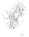
- a sensor 58 is arranged, which is connected via an actuating device 60 with the pivot linkage 26, in particular with the first link 30 and with its flat profile 30 '.
- the sensor 58 makes it possible, for example, to reproduce a swivel angle relative to the loader rocker 12.
- the actuating device 60 comprises an axis of rotation A, a first rotary lever 62, a second rotary lever 63 and a control arm 64.
- the first rotary lever is non-rotatably connected to the axis of rotation A, so that by actuation of the first rotary lever 62, the axis of rotation A is rotated and the sensor 58 is actuated ,
- the sensor information is routed via a corresponding data transfer, for example by cable or radio (not shown) to a data processor or to a data display (not shown) in a known manner and displayed.
- the axis of rotation A can pass on the angle information directly to the sensor (as in the illustrated embodiment) or it can be a further translation in mechanical form, for example by a gear stage.
- the control arm 64 is pivotable at a hinge point 66, that is articulated, connected to the first rotary lever 62. Further, the control arm 64 is pivotally mounted at a further pivot point 68, so articulated, on the second pivot lever 63.
- the second rotary lever 63 is rotatable with connected to the pivot pin 55, which in turn rotatably connected to the first link 30, 32 in conjunction.
- the sensor 58 is mounted on a mounting plate 70.
- the loader rocker 12 has on its inner side on the rocker part 14 in the region of the pivot linkage 24 an opening 74, which in the wall of the loader rocker 12, and the rocker part 14, access to a cavity 76 in the loader rocker 12, and the rocker part 14th , forms.
- the opening 74 is keyhole-shaped or formed as a slot cutout and has mounting holes 78 on its long sides.
- the opening 74 may alternatively be formed rectangular as a rectangular cutout.
- the mounting holes 78 are formed as through holes.
- the mounting plate 70 is oval-shaped, wherein the dimensions of the mounting plate are selected so that the mounting plate 70 can be inserted through the opening 74.
- On the mounting plate 70 corresponding mounting holes are provided, which coincide with the mounting holes 78 at the opening 74.
- the mounting holes on the mounting plate 70 are provided with a thread such that the mounting plate 70 by means of threaded screws 82 to the wall of the loader rocker 12, and the swing member 14, fastened (see FIGS. 6 and 10).
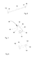
- FIGS. 6 to 8 show the actuator 60 in their individual parts, which includes the first rotary lever 62, the control arm 64 and the second rotary lever 63.
- the first rotary lever 62 is connected to the sensor via an axis of rotation 84 formed on the rotary lever 62.
- the first rotary lever 62 comprises two lever discs 86, 88 between which a gap 90 is formed. Further, recesses 92, 94 are formed on both retaining disks 86, 88 at a location on the circumference, which constitute a bolt receptacle 96.
- the control arm 64 is formed as a rigid rod or rod and has at its two ends a thread 97. Further, at both ends of the control arm 64 transversely to the control arm 64 threaded tapped bolts 98, 100 are attached.
- the second rotary lever 63 is formed as a pin or bolt and has at its one end a fork 102, through which a bore 104 extends, such that a gap 106 formed between the fork 102 extends transversely to the bore 104. At its other end, the second rotary lever has a shoulder 106.
- transverse bore 108 which is provided with a paragraph 106 corresponding paragraph 110.
- the diameter of the transverse bore 108 substantially corresponds to the small diameter of the second rotary lever 63.
- annular groove is mounted, in which a snap ring 110 is inserted (see FIG. 4 ).
- An assembly of the actuator 60 and the sensor 58 to the loader rocker 12 is such that first the mounting plate 70 is inserted with sensor 58 and first rotary lever 62 through the opening 74 in the cavity 76 and the mounting plate 70 is positioned transversely to the opening 74, so that cover the mounting holes 78 (and the mounting plate) and the mounting plate 70 bridges the opening widthwise (in the transverse direction).
- the mounting plate 70 is fixed to the wall of the loader rocker 12 and the swing member 14, wherein the threaded screw heads outside the cavity 76, on the outside of the wall and the mounting plate 70 with sensor 58 and first pivot lever 62 within the cavity 76th located on the inside of the wall.
- the remaining parts of the actuator 60 are preassembled by inserting the bolt 98 of the control arm 64 into the bore 104 of the second rotary lever. Subsequently, the control arm 64 is screwed to the bolt 98, so that the control arm 64 is pivotally mounted in the fork 102.
- the second bolt 100 is also with the Control arm 64 connected.
- the control arm 64 and the bolts 98, 100 attached thereto as well as the second rotary lever 63 are now passed through a mounting opening 112 below the pivot pin 55 (see FIG FIG. 4 ) and guided through the transverse bore 108 of the pivot pin 55.
- the sensor 58 itself is now in the cavity 76 of the loader rocker 12 (see FIG. 4 and 5 ) and is protected by the wall of the loader rocker 12 from any external influences. The same applies to the actuating device 60 of the sensor 58 and to a wiring of the sensor 58, which can be easily guided through the cavity 76.
- the actuator 60 By connecting the first rotary lever 62 with the pivot pin 55 and with the first link 30 of the pivot link, which is rotatably connected to the pivot pin 55, the actuator 60 is brought into contact with the pivot link 24. A pivoting movement of the tool carrier 26 or a tool attached thereto is thus transmitted by the first link 30 of the pivot link 24 to the second rotary lever 63, from there to the control arm 64 and from there to the first rotary lever 62. This then actuates the axis of rotation A and generates a corresponding swivel angle signal on the sensor 58.
- the swivel angle signal represents a swivel angle or a change in the swivel angle between the tool carrier 26 and loader rocker 12.
- the actuator 60 can be executed in a compact form with a small design, so that in total, in addition to the protection of Sensor 58 through the wall on the cavity 76, given a small attack surface for external objects and the installation is easy to implement.
Landscapes
- Engineering & Computer Science (AREA)
- Mining & Mineral Resources (AREA)
- Civil Engineering (AREA)
- General Engineering & Computer Science (AREA)
- Structural Engineering (AREA)
- Mechanical Engineering (AREA)
- Operation Control Of Excavators (AREA)
- Component Parts Of Construction Machinery (AREA)
- Shovels (AREA)
Abstract
Description
- Die Erfindung betrifft einen Lader mit einer Laderschwinge und einem an der Laderschwinge angeordneten Werkzeugträger oder Werkzeug, wobei der Werkzeugträger oder das Werkzeug an einem ersten Schwenkpunkt mit der Laderschwinge und an einem zweiten Schwenkpunkt mit einem Schwenkgestänge verbunden ist, wobei das Schwenkgestänge einen ersten und einen zweiten Lenker umfasst, die an einem ersten Lenkerpunkt schwenkbar miteinander in Verbindung stehen und wobei der erste Lenker an einem zweiten Lenkerpunkt an der Laderschwinge und der zweite Lenker an einem zweiten Lenkerpunkt an dem zweiten Schwenkpunkt mit dem Werkzeugträger oder dem Werkzeug schwenkbar verbunden sind, ferner ein Sensor vorgesehen ist, mittels welchem ein Schwenkwinkel zwischen Werkzeugträger oder Werkzeug und Laderschwinge erfassbar ist.
- Lader, wie beispielsweise Frontlader, Radlader, Teleskoplader, Hecklader und dergleichen, sind bekannt. Es ist ferner bekannt derartige Lader mit einer Sensorvorrichtung auszustatten, mittels welcher ein Schwenkwinkel eines am Lader angeordneten Werkzeugträgers oder Werkzeugs gemessen wird, wobei der Schwenkwinkel eine Schwenkposition des Werkzeugträgers insbesondere relativ zu einer Laderschwinge oder einem Ausleger des Laders angibt. Die Anordnung einer Sensoreinrichtung am Lader gestaltet sich oftmals schwierig oder aufwändig, da der Sensor erheblichen Beanspruchungen ausgesetzt sein kann und insbesondere Verschmutzungen und Beschädigungen durch Ladegut standhalten muss und entsprechend robust ausgebildet oder geschützt positioniert werden muss. So werden magnetostriktive Sensoren beispielsweise direkt an einem Hubzylinder des Laders angeordnet, so dass der Hub des Zylinders gemessen und auf den Schwenkwinkel am Werkzeug rückgeschlossen werden kann. Magnetostriktive Sensoren sind in der Regel aufwändig zu installieren und entsprechend teuer. Alternativ ist es bekannt, Drehwinkel- oder Rotationssensoren am Lader, beispielsweise an der Laderschwinge, am Werkzeugträger oder am Schwenkgestänge des Laders, anzuordnen. Hier stellt sich das Problem, dass der Sensor zusätzlich geschützt werden muss, beispielsweise durch eine robuste Abdeckung. Eine Abdeckung kann zum einen die Sicht auf das Werkzeug einschränken, zum anderen verursacht sie zusätzlichen Montage- und Kostenaufwand.
- Die der Erfindung zugrunde liegende Aufgabe wird darin gesehen, einen Frontlader der eingangs genannten Art derart auszubilden, dass die vorgenannten Probleme überwunden werden.
- Die Aufgabe wird erfindungsgemäß durch die Lehre des Patentanspruchs 1 gelöst. Weitere vorteilhafte Ausgestaltungen und Weiterbildungen der Erfindung gehen aus den Unteransprüchen hervor.
- Erfindungsgemäß wird ein Frontlader der eingangs genannten Art derart ausgebildet, dass der Sensor in einem Hohlraum am Lader positioniert ist und eine mit dem Sensor verbundene Betätigungseinrichtung angeordnet ist, welche sich in dem Hohlraum erstreckt und mit einem im zweiten Lenkerpunkt angeordneten Schwenkbolzen des ersten Lenkers verbunden ist, wobei der Schwenkbolzen drehfest mit dem ersten Lenker verbunden ist. Dadurch, dass der Sensor in einem Hohlraum am Lader angeordnet ist, wird dieser durch äußere Einflüsse geschützt, bzw. automatisch abgedeckt, so dass von außen einwirkende Gegenstände keinen Zugang zum Sensor haben. Die Montage gestaltet sich zudem einfach, da keine zusätzlichen Abdeckungen erforderlich sind. Der Hohlraum wird vorzugsweise nahe des Schwenkgestänges gesucht, so dass die Betätigungseinrichtung kompakt ausgeführt und eine Schwenkbewegung direkt am Werkzeugträger oder am Schwenkgestänge aufgenommen und gemessen werden kann. Damit werden Ungenauigkeiten vermieden und Fehlertoleranzen klein gehalten. Der Sensor kann beispielsweise als magnetischer, potentiometrischer oder optischer Drehwinkelsensor oder Drehsensor bzw. Rotationssensor ausgebildet sein.
- Der Hohlraum kann beispielsweise in der Laderschwinge ausgebildet sein, vorzugsweise nahe des Schwenkgestänges. So kann die Laderschwinge oder ein Ausleger als Hohlprofil ausgebildet sein, so dass die Öffnung als Ausschnitt einer Hohlprofilwandung ausgebildet ist. Durch entsprechende Positionierung und Ausgestaltung der Öffnung gestaltet sich auch die Montage als einfach und unkompliziert. Auch eine Verkabelung für den Sensor kann durch das Innere des Hohlprofils geführt werden, so dass ein Schutz gegen Beschädigung von außen für den Sensor und der Verkabelung gegeben ist. Alternativ könnte der Sensor auch in einem Hohlraum des Schwenkgestänges oder des Werkzeugträgers, beispielsweise zwischen zwei beabstandeten Lenkern oder Trageblechen positioniert werden, wobei die Öffnung entweder durch eine Aussparung an den Lenkern oder Trageblechen oder durch die Beabstandung der Lenker bzw. Tragebleche zueinander ausgebildet wird.
- Die Betätigungseinrichtung umfasst eine mit dem Sensor verbundene Drehachse, einen mit der Drehachse drehfest verbundenen ersten Drehhebel, einen mit dem Schwenkbolzen drehfest vebundenen zweiten Drehhebel und einen Steuerarm, wobei der Steuerarm den ersten Drehhebel mit dem zweiten Drehhebel derart schwenkbar verbindet, dass eine Drehbewegung des Schwenkbolzenz von den zweiten Drehhebel über den Steuerarm auf den ersten Drehhebel und damit auf den Sensor übertragen wird. Die Drehachse dient dabei als Drehwinkelgeber bzw. - übertrager für den Sensor und kann direkt oder, beispielsweise durch eine Drehwinkelübersetzung, indirekt mit dem Sensor verbunden sein. Der erste Drehhebel ist als starrer Verbindungsarm zur Drehachse des Sensors ausgebildet und erstreckt sich radial zu dieser. Der erste Drehhebel überträgt somit eine am ersten Drehhebel ausgeübte Bewegung direkt auf die Drehachse des Sensors. Der zweite Drehhebel ist als starrer Verbindungsarm zur Drehachse des Schwenkbolzens ausgebildet und erstreckt sich radial zu diesem. Der zweite Drehhebel überträgt somit eine am Schwenkbolzen ausgeführte Drehbewegung auf den Steuerarm. Durch den Steuerarm, der als schwenkbarer Lenker oder als Verbindungsstange ausgebildet ist, wird eine Drehung des Schwenkbolzen folglich in eine rotatorische Bewegung der Drehachse am Sensor übertragen.
- Der zweite Drehhebel kann ein sich durch eine Querbohrung im Schwenkbolzen erstreckender Querbolzen sein. Beispielsweise kann der Querbolzen durch die Querbohrung geführt und über eine Sicherung, beispielsweise einem Sprengring, in der Querbohrung gehalten werden. Der Querbolzen kann jedoch auch ein Gewinde umfassen, mit welchem er in ein Gewinde der Querbohurng geschraubt wird.
- Erfindungsgemäß kann der Lader als Frontlader, Radlader, Teleskoplader oder Hecklader ausgebildet sein, wobei die Laderschwinge als Laderschwinge eines Frontladers oder Radladers bzw. als Ausleger eines Teleskopladers oder Heckladers ausgebildet ist. Frontlader und Hecklader können an landwirtschaftlichen Schleppern oder Baumaschinen als Anbaugeräte Verwendung finden. Auch andere laderartige Geräte und Maschinen, die über eine Ladeerschwinge bzw. einen Ausleger Verfügen, beispielsweise Baumaschinen, wie Bagger, Planierraupen, oder Forstmaschinen zum Abforsten von Wäldern, oder gegebenenfalls auch Kräne, sollen unter den Begriff Lader fallen.
- Anhand der Figuren, die ein Ausführungsbeispiel der Erfindung zeigen, werden nachfolgend die Erfindung sowie weitere Vorteile und vorteilhafte Weiterbildungen und Ausgestaltungen der Erfindung näher beschrieben und erläutert.
- Es zeigt:
- Fig. 1
- eine perspektivische Vorderansicht eines Laders für den vorderen Bereich einer Laderschwinge,
- Fig. 2
- eine perspektivische Seitenansicht des Laders aus
Figur 1 einer in Vorwärtsfahrtrichtung rechten inneren Seite der Laderschwinge in einer vergrößerten Darstellung eines Teils eines Schwenkgestänges - Fig. 3
- eine perspektivische Seitenansicht der äußeren teilgeöffneten Seite der Laderschwinge aus
Figur 2 von vorn mit einer im Hohlraum der Laderschwinge angeordneten Betätigungseinrichtung für einen Sensor, - Fig. 4
- eine perspektivische Seitenansicht der äußeren teilgeöffneten Seite aus
Figur 3 von unten und hinten, - Fig. 5
- eine perspektivische Seitenansicht der inneren Seite aus
Figur 2 in einer vergrößerten Darstellung eines Bereichs einer Öffnung mit einem Sensor, - Fig. 6
- eine perspektivische Seitenansicht eines Steuerarms einer Betätigungseinrichtung für den Sensor aus
Figur 5 , - Fig. 7
- eine perspektivische Seitenansicht eines ersten Drehhebels der Betätigungseinrichtung aus
Figur 6 und - Fig. 8
- eine perspektivische Seitenansicht eines zweiten Drehhebels der Betätigungseinrichtung aus
Figur 6 . - In
Figur 1 ist ein Teil eines Laders 10 in Form eines Frontladers gezeigt. Der Frontlader wird in Kombination mit einem Trägerfahrzeug, beispielsweise einem landwirtschaftlichen Schlepper (nicht gezeigt), betrieben und findet üblicherweise Verwendung in der Landwirtschaftn und im Baumaschinenbereich. Bei einem an ein Trägerfahrzeug fest (unlösbar) montierten Lader 10 spricht man von einem Radlader, der jedoch im Sinne dieser Erfindung im Wesentlichen einem Trägerfahrzeug mit lösbar montiertem Lader 10 (Frontlader) gleicht. - Der Lader 10 umfasst eine Laderschwinge 12 oder Ausleger. In dem dargestellten Ausführungsbeispiel umfasst die Laderschwinge 12 einen ersten und einen zweiten
- Schwingenteil 14, 16, die parallel zueinander geführt und über eine Traverse 18 miteinander verbunden sind. Die Laderschwinge 12 bzw. der Ausleger können jedoch auch nur einen Schwingenteil umfassen, wie es beispielsweise bei Teleskoplader, Kränen, Bagger oder Forstmaschinen der Fall sein kann.
- Die Laderschwinge 12 umfasst ferner einen ersten und zweiten Hubzylinder 20, 22, an denen sich ein Schwenkgestänge 24 mit einem sich quer zur Laderschwinge 12 erstreckenden Werkzeugträger 26 anschließt. Der Werkzeugträger 26 kann über eine Werkzeugaufnahme 28 mit einem Werkzeug (nicht gezeigt) bestückt werden. Beispielsweise bei Radladern, können auch fest installierte Werkzeuge in Form einer Schaufel Verwendung finden, so dass auf einen Werkzeugträger 26 verzichtet werden kann und das Schwenkgestänge 24 direkt am Werkzeug angreift.
- Wie ferner in
Figur 2 dargestellt ist, umfasst das Schwenkgestänge 24 beidseitig der Laderschwinge 12, also an jedem Schwingenteil 14, 16, einen ersten Lenker 30, 32 und einen zweiten Lenker 34, 36, die an einem ersten Lenkerpunkt 38, 40 miteinander gelenkig in Verbindung stehen, wobei die genannten Hubzylinder 20, 22 am ersten Lenkerpunkt 38, 40 angreifen. Die genannten Lenker 30, 32, 34, 36 werden aus dynamischen und statischen Gründen üblicherweise durch paarweise, in einem Abstand zueinander angeordnete, Flachprofile ausgebildet sein, so dass das Schwenkgestänge 20 beidseitig der Laderschwinge 12 für jeden der genannten Lenker 30, 32, 34, 36 ein Flachprofilpaar 30', 30", 32', 32", 34', 34" und 36', 36" umfasst. Die genannten Lenker 30, 32, 34, 36 können jedoch auch als einteilige Lenker 30, 32, 34, 36 (nicht paarweise angeordnete Flachprofilpaare 30', 30", 32', 32", 34', 34" und 36', 36") angeordnet werden. - Der Werkzeugträger 26 weist beidseitig einen ersten Schwenkpunkt 42, 44 auf, an dem er jeweils mit einem Schwingenteil 14, 16 der Laderschwinge 12 schwenkbar verbunden ist (Schwenkpunkt 42 am Schwingenteil 14, Schwenkpunkt 44 am Schwingenteil 16). Ferner weist der Werkzeugträger 26 beidseitig einen zweiten Schwenkpunkt 46, 48 auf, an dem er jeweils an einem zweiten Lenkerpunkt 50, 52 des zweiten Lenkers 34, 36 mit diesem verbunden ist. An einem zweiten Lenkerpunkt 54, 56 des ersten Lenkers 30, 32 ist dieser über einen Schwenkbolzen 55, 57, mit einem Schwingenteil 14, 16 der Laderschwinge 12 schwenkbar verbunden, wobei der Schwenkbolzen 55, 57 jeweils drehfest mit dem ersten Lenker 30, 32. Die oben beschrieben Anordnung bewirkt, dass der Werkzeugträger 26 durch die genannten Hubzylinder 20, 22 über die ersten und zweiten Lenker 30, 32, 34, 36 bzw. über das Schwenkgestänge 24 kontrolliert mit einer festgelegten Kinematik gekippt werden kann, wobei ein bestimmter Kippwinkel des Werkzeugträgers 26 mit einer festen Schwenkbewegung der ersten und zweiten Lenker 30, 32, 34, 36 einhergeht (siehe insbesondere
Figur 2 ). - Zur Messung und optischen und/oder zahlenmäßigen Wiedergabe des Schwenkwinkels bzw. Kippwinkels des Werkzeugträgers 26 ist ein Sensor 58 angeordnet, der über eine Betätigungseinrichtung 60 mit dem Schwenkgestänge 26, insbesondere mit dem ersten Lenker 30 bzw. mit dessen Flachprofil 30' verbunden ist. Der Sensor 58 ermöglicht beispielsweise die Wiedergabe eines Schwenkwinkels relativ zur Laderschwinge 12.
- Die Betätigungseinrichtung 60 umfasst eine Drehachse A, einen ersten Drehhebel 62 einen zweiten Drehhebel 63 und einen Steuerarm 64. Der erste Drehhebel ist drehfest mit der Drehachse A verbunden, so dass durch Betätigung des ersten Drehhebels 62 die Drehachse A verdreht und der Sensor 58 betätigt wird. Die Sensorinformation wird über einen entsprechenden Datentransfer, beispielsweise per Kabel oder Funk (nicht gezeigt) an einen Datenprozessor oder an eine Datenanzeige (nicht gezeigt) in bekannter Weise geleitet und zur Anzeige gebracht. Die Drehachse A kann die Winkelinformation direkt an den Sensor weitergeben (wie im dargestellten Ausführungsbeispiel) oder es kann eine weitere Übersetzung in mechanischer Form, beispielsweise durch eine Zahnradstufe, erfolgen. Der Steuerarm 64 ist an einem Gelenkpunkt 66 schwenkbar, also gelenkig, mit dem ersten Drehhebel 62 verbunden. Ferner ist der Steuerarm 64 an einem weiteren Gelenkpunkt 68 schwenkbar, also gelenkig, am zweiten Drehhebel 63 befestigt. Der zweite Drehhebel 63 ist drehfest mit dem Schwenkbolzen 55 verbunden, welcher wiederum drehfest mit dem ersten Lenker 30, 32 in Verbindung steht.
- Der Sensor 58 ist auf einer Montageplatte 70 gelagert. Die Laderschwinge 12 weist auf ihrer Innenseite am Schwingenteil 14 im Bereich der Schwenkgestänge 24 eine Öffnung 74 auf, die in der Wandung der Laderschwinge 12, bzw. des Schwingenteils 14, einen Zugang zu einem Hohlraum 76 in der Laderschwinge 12, bzw. des Schwingenteils 14, bildet. Die Öffnung 74 ist schlüssellochförmig oder als Langlochausschnitt ausgebildet und weist Befestigungsbohrungen 78 an ihren langen Seiten auf. Die Öffnung 74 kann alternativ auch rechteckig als Rechteckausschnitt ausgebildet sein. Die Befestigungsbohrungen 78 sind als Durchgangsbohrungen ausgebildet.
- Die Montageplatte 70 ist ovalförmig ausgebildet, wobei die Abmessungen der Montageplatte so gewählt sind, dass die Montageplatte 70 durch die Öffnung 74 einführbar ist. An der Montageplatte 70 sind entsprechende Befestigungsbohrungen vorgesehen, die sich mit den Befestigungsbohrungen 78 an der Öffnung 74 decken. Die Befestigungsbohrungen an der Montageplatte 70 sind mit einem Gewinde ausgestattet, derart, dass sich die Montageplatte 70 durch Gewindeschrauben 82 an die Wandung der Laderschwinge 12, bzw. des Schwingenteils 14, befestigen lässt (siehe
Figuren 6 und 10). -
Figuren 6 bis 8 zeigen die Betätigungseinrichtung 60 in ihren Einzelteilen, wobei diese den ersten Drehhebel 62, den Steuerarm 64 und den zweiten Drehhebel 63 umfasst. Der erste Drehhebel ist 62 ist über eine am Drehhebel 62 ausgebildete Drehachse 84 mit dem Sensor verbunden. Der erste Drehhebel 62 umfasst zwei Hebelscheiben 86, 88 zwischen denen ein Spalt 90 ausgebildet ist. Ferner sind an beiden Haltescheiben 86, 88 an einer Stelle am Umfang Ausnehmungen 92, 94 ausgebildet, die eine Bolzenaufnahme 96 darstellen. - Der Steuerarm 64 ist als starrer Stab oder Stange ausgebildet und weist an seinen beiden Enden ein Gewinde 97 auf. Ferner sind an beiden Enden des Steuerarms 64 quer zum Steuerarm 64 mit Gewindebohrungen versehene Bolzen 98, 100 befestigt.
- Der zweite Drehhebel 63 ist als Stift oder Bolzen ausgebildet und weist an seinem einen Ende eine Gabelung 102 aus, durch welche sich eine Bohrung 104 erstreckt, derart, dass ein sich zwischen der Gabelung 102 ausgebildeter Spalt 106 quer zur Bohrung 104 erstreckt. An seinem anderen Ende weist der zweite Drehhebel einen Absatz 106 auf.
- Ferner ist am Schwenkbolzen 55 eine Querbohrung 108, die mit einem zum Absatz 106 korrespondierendem Absatz 110 versehen ist. Der Durchmesser der Querbohrung 108 entspricht im Wesentlichen dem kleinen Durchmesser des zweiten Drehhebels 63. Ferner ist in der Querbohrung 108 eine Ringnut angebracht, in die ein Sprengring 110 eingesetzt ist (siehe
Figur 4 ). - Eine Montage der Betätigungseinrichtung 60 und des Sensors 58 an die Laderschwinge 12 erfolgt derart, dass zunächst die Montageplatte 70 mit Sensor 58 und erstem Drehhebel 62 durch die Öffnung 74 in den Hohlraum 76 eingeführt und die Montageplatte 70 quer zur Öffnung 74 positioniert wird, so dass sich die Befestigungsbohrungen 78 (und die der Montageplatte) decken und die Montageplatte 70 die Öffnung der Breite nach (in Querrichtung) überbrückt. Über die Gewindeschrauben 82 wird die Montageplatte 70 an die Wandung der Laderschwinge 12 bzw. des Schwingenteils 14 befestigt, wobei sich die Gewindeschraubenköpfe außerhalb des Hohlraums 76, an der Außenseite der Wandung und die Montageplatte 70 mit Sensor 58 und erstem Drehhebel 62 innerhalb des Hohlraums 76 an der Innenseite der Wandung befinden. Als nächstes werden die verbleibenden Teile der Betätigungseinrichtung 60 vormontiert, indem der Bolzen 98 des Steuerarms 64 in die Bohrung 104 des zweiten drehhebels eingeführt wird. Anschließend wird der Steuerarm 64 mit dem Bolzen 98 verschraubt, so dass der Steuerarm 64 in der Gabelung 102 schwenkbar gelagert ist. Der zweite Bolzen 100 wird ebenfalls mit dem Steuerarm 64 verbunden. Der Steuerarm 64 sowie die daran befestigten Bolzen 98, 100 als auch der zweite Drehhebel 63 werden nun durch eine Montageöffnung 112 unterhalb des Schwenkbolzens 55 (siehe
Figur 4 ) eingeführt und durch die Querbohrung 108 des Schwenkbolzens 55 geführt. Nach Einführen in die Querbohrung 108 wird der Sprengring 110 eingesetzt, so dass der zweite Drehhebel 63 durch Sprengring 110 und Absatz 106 gegen axiales Verschieben gesichert ist. Anschließend wird über die Öffnung 74 von außen der Bolzen 100 des Steuerarms 64 mit den Ausnehmungen 92, 94 der Hebelscheiben 86, 88 in Verbindung gebracht, so dass der Steuerarm 62 über den Bolzen 100 und den Spalt 90 zwischen den Hebelscheiben 86, 88 schwenkbar gelagert ist. - Der Sensor 58 selbst befindet sich nun im Hohlraum 76 der Laderschwinge 12 (siehe
Figur 4 und5 ) und wird durch die Wandung der Laderschwinge 12 vor jeglichen äußeren Einflüssen geschützt. Gleiches gilt für die Betätigungseinrichtung 60 des Sensors 58 sowie für eine Verkabelung des Sensors 58, welche bequem durch den Hohlraum 76 geführt werden kann. - Durch Verbinden des ersten Drehhebels 62 mit dem Schwenkbolzen 55 bzw. mit ersten Lenker 30 des Schwenkgestänges, welcher drehfest mit dem Schwenkbolzen 55 verbunden ist, wird die Betätigungseinrichtung 60 mit dem Schwenkgestänge 24 in Verbindung gebracht. Eine Schwenkbewegung des Werkzeugträgers 26 bzw. eines daran befestigten Werkzeugs wird somit durch den ersten Lenker 30 des Schwenkgestänges 24 auf den zweiten Drehhebel 63, von dort auf den Steuerarm 64 und von dort auf den ersten Drehhebel 62 übertragen. Dieser betätigt dann die Drehachse A und erzeugt ein entsprechendes Schwenkwinkelsignal am Sensor 58. Das Schwenkwinkelsignal stellt dabei einen Schwenkwinkel bzw. eine Änderung des Schwenkwinkels zwischen Werkzeugträger 26 und Laderschwinge 12 dar. Durch die nahe Positionierung des Sensors 58 am Schwenkgestänge 24 werden Messfehler klein gehalten. Ferner kann auch die Betätigungseinrichtung 60 in kompakter Form mit kleiner Bauweise ausgeführt werden, so dass insgesamt, neben dem Schutz des Sensors 58 durch die Wandung am Hohlraum 76, eine geringe Angriffsfläche für äußere Gegenstände gegeben und die Montage auf einfache realisierbar ist.
Claims (5)
- Lader (10) mit einer Laderschwinge (12) und einem an der Laderschwinge (12) angeordneten Werkzeugträger (26) oder Werkzeug, wobei der Werkzeugträger (26) oder das Werkzeug an einem ersten Schwenkpunkt (42, 44) mit der Laderschwinge (12) und an einem zweiten Schwenkpunkt (46, 48) mit einem Schwenkgestänge (24) verbunden ist, wobei das Schwenkgestänge (24) einen ersten und einen zweiten Lenker (30, 32, 34, 36) umfasst, die an einem ersten Lenkerpunkt (38, 40) schwenkbar miteinander in Verbindung stehen und wobei der erste Lenker (30, 32) an einem zweiten Lenkerpunkt (54, 56) an der Laderschwinge (12) und der zweite Lenker (34, 36) an einem zweiten Lenkerpunkt (50, 52) an dem zweiten Schwenkpunkt (46, 48) mit dem Werkzeugträger (26) oder dem Werkzeug schwenkbar verbunden sind, ferner ein Sensor (58) vorgesehen ist, mittels welchem ein Schwenkwinkel zwischen Werkzeugträger (26) oder Werkzeug und Laderschwinge (12) erfassbar ist, dadurch gekennzeichnet, dass der Sensor (58) in einem Hohlraum (76) am Lader (10) positioniert ist und eine mit dem Sensor (58) verbundene Betätigungseinrichtung (60) angeordnet ist, welche sich in dem Hohlraum erstreckt und mit einem im zweiten Lenkerpunkt (54) angeordneten Schwenkbolzen des ersten Lenkers (30, 32) verbunden ist, wobei der Schwenkbolzen drehfest mit dem ersten Lenker (30, 32) verbunden ist.
- Lader (10) nach Anspruch 1, dadurch gekennzeichnet, dass der Hohlraum (76) in der Laderschwinge (12) ausgebildet ist.
- Lader (10) nach Anspruch 1 oder 2, dadurch gekennzeichnet, dass die Betätigungseinrichtung (60) eine mit dem Sensor (58) verbundene Drehachse (A), einen mit der Drehachse (A) drehfest verbundenen ersten Drehhebel, einen mit dem Schwenkbolzen drehfest vebundenen zweiten Drehhebel (62) und einen Steuerarm (64) umfasst, wobei der Steuerarm (64) den ersten Drehhebel mit dem zweiten Drehhebel derart schwenkbar verbindet, dass eine Drehbewegung des Schwenkbolzens von den zweiten Drehhebel über den Steuerarm auf den ersten Drehhebel und damit auf den Sensor übertragen wird.
- Lader (10) nach Anspruch 3, dadurch gekennzeichnet, dass der zweite Drehhebel ein sich durch eine Querbohrung im Schwenkbolzen erstreckender Querbolzen ist.
- Lader (10) nach einem der vorhergehenden Ansprüche, dadurch gekennzeichnet, dass der Lader (10) als Frontlader, Radlader, Teleskoplader oder Hecklader ausgebildet ist, wobei die Laderschwinge (12) als Laderschwinge eines Frontladers oder Radladers, oder als Ausleger eines Teleskopladers oder Heckladers ausgebildet ist.
Applications Claiming Priority (1)
| Application Number | Priority Date | Filing Date | Title |
|---|---|---|---|
| DE102012021191.0A DE102012021191B4 (de) | 2012-10-30 | 2012-10-30 | Lader |
Publications (2)
| Publication Number | Publication Date |
|---|---|
| EP2728072A1 true EP2728072A1 (de) | 2014-05-07 |
| EP2728072B1 EP2728072B1 (de) | 2019-03-13 |
Family
ID=49356301
Family Applications (1)
| Application Number | Title | Priority Date | Filing Date |
|---|---|---|---|
| EP13188675.6A Active EP2728072B1 (de) | 2012-10-30 | 2013-10-15 | Lader |
Country Status (7)
| Country | Link |
|---|---|
| US (2) | US9085869B2 (de) |
| EP (1) | EP2728072B1 (de) |
| CN (1) | CN103790194A (de) |
| BR (1) | BR102013027643A2 (de) |
| DE (1) | DE102012021191B4 (de) |
| EA (1) | EA201301042A1 (de) |
| IN (1) | IN2013MU02665A (de) |
Cited By (1)
| Publication number | Priority date | Publication date | Assignee | Title |
|---|---|---|---|---|
| CN105650119A (zh) * | 2016-03-11 | 2016-06-08 | 赵静 | 一种旋转轴护筒 |
Families Citing this family (10)
| Publication number | Priority date | Publication date | Assignee | Title |
|---|---|---|---|---|
| DE102012021191B4 (de) | 2012-10-30 | 2016-03-03 | Deere & Company | Lader |
| DE102015004819A1 (de) * | 2015-04-14 | 2016-10-20 | Liebherr-Werk Bischofshofen Gmbh | Arbeitsmaschine |
| AT517147B1 (de) * | 2015-05-04 | 2017-08-15 | Ing Hauer Ronald | Ausleger für ein Nutzfahrzeug |
| US10030366B2 (en) | 2016-04-04 | 2018-07-24 | Caterpillar Inc. | Drawbar position determination with rotational sensors |
| SE1651327A1 (en) * | 2016-10-10 | 2018-04-03 | Loe Ab | Rotary sensor arrangement for mounting to a pivot arm arrangement and method for mounting a rotary sensor arrangement to a pivoting arm arrangement |
| JP7280345B1 (ja) * | 2021-12-28 | 2023-05-23 | 日立建機株式会社 | 作業車両 |
| US12398529B2 (en) | 2022-10-20 | 2025-08-26 | Deere & Company | Loader latching assist method and apparatus |
| USD1026968S1 (en) * | 2022-11-04 | 2024-05-14 | Deere & Company | Loader carrier for implements |
| JP1801893S (ja) * | 2023-10-27 | 2025-06-24 | 車両用中央コンソール | |
| USD1096540S1 (en) * | 2023-10-27 | 2025-10-07 | Bugatti International SA | Accelerator pedal for vehicles |
Citations (6)
| Publication number | Priority date | Publication date | Assignee | Title |
|---|---|---|---|---|
| JPH0312948U (de) * | 1989-06-16 | 1991-02-08 | ||
| JPH06102905B2 (ja) * | 1987-09-30 | 1994-12-14 | 株式会社クボタ | ブーム型作業機の作業具姿勢検出装置 |
| JPH072553U (ja) * | 1993-06-15 | 1995-01-13 | 株式会社小松製作所 | パワーショベル用バケットポジショナ |
| JP2000054423A (ja) * | 1998-08-04 | 2000-02-22 | Yanmar Agricult Equip Co Ltd | フロントロ−ダ |
| JP2000170218A (ja) * | 1998-12-08 | 2000-06-20 | Komatsu Ltd | 油圧ショベルのアーム角度検出器取付構造 |
| JP3194637B2 (ja) * | 1993-02-01 | 2001-07-30 | ヤンマーディーゼル株式会社 | 回動部におけるセンサ取付構造 |
Family Cites Families (19)
| Publication number | Priority date | Publication date | Assignee | Title |
|---|---|---|---|---|
| SU789377A1 (ru) | 1979-03-14 | 1980-12-23 | Сибирский автомобильно-дорожный институт им.В.В.Куйбышева | Ковшовый погрузчик |
| JPS6457150A (en) * | 1987-08-27 | 1989-03-03 | Ricoh Kk | Apparatus for measuring refractive index of liquid |
| JPH0634431Y2 (ja) * | 1987-09-30 | 1994-09-07 | 株式会社クボタ | ブーム型作業機の作業具姿勢検出器 |
| JP2691299B2 (ja) | 1989-06-12 | 1997-12-17 | 株式会社ニコン | 基板ホルダ |
| JP2800333B2 (ja) * | 1989-12-25 | 1998-09-21 | 日本電気株式会社 | モジュール制御装置 |
| RU2009295C1 (ru) | 1990-05-08 | 1994-03-15 | Государственный научно-исследовательский институт по промышленным тракторам | Способ набора сыпучих материалов и устройство для его осуществления |
| JPH06102905A (ja) * | 1992-09-18 | 1994-04-15 | Hitachi Ltd | フィードフォワード/フィードバック制御装置 |
| JP3260911B2 (ja) | 1993-06-15 | 2002-02-25 | 住友大阪セメント株式会社 | セメントクリンカー及びその製造方法 |
| CN1748062A (zh) * | 2003-02-26 | 2006-03-15 | 新卡特彼勒三菱株式会社 | 建筑机械中臂角度传感器装置 |
| JP2004278288A (ja) * | 2003-02-26 | 2004-10-07 | Shin Caterpillar Mitsubishi Ltd | 建設機械におけるアーム角度センサ装置 |
| US7568878B2 (en) | 2005-07-22 | 2009-08-04 | Frey Industries Limited | Loader boom arm |
| JP4408428B2 (ja) * | 2005-08-30 | 2010-02-03 | 日立建機株式会社 | 作業機械の作業具角検出装置 |
| DE102007029795A1 (de) * | 2007-06-27 | 2009-01-08 | Deere & Company, Moline | Ladegerät |
| JP5114133B2 (ja) * | 2007-08-27 | 2013-01-09 | 株式会社クボタ | フロントローダ |
| US20110301781A1 (en) * | 2008-11-26 | 2011-12-08 | Volvo Construction Equipment | Method for calibrating an angle sensor and vehicle with an angle sensor |
| DE102012021192B4 (de) * | 2012-10-30 | 2016-03-03 | Deere & Company | Lader |
| DE102012021191B4 (de) | 2012-10-30 | 2016-03-03 | Deere & Company | Lader |
| JP5401616B1 (ja) * | 2013-01-18 | 2014-01-29 | 株式会社小松製作所 | 油圧ショベルおよび油圧ショベルの油圧シリンダのストローク計測方法 |
| US20150098786A1 (en) * | 2013-10-03 | 2015-04-09 | Caterpillar Inc. | Work tool position sensing assembly |
-
2012
- 2012-10-30 DE DE102012021191.0A patent/DE102012021191B4/de not_active Expired - Fee Related
-
2013
- 2013-08-14 IN IN2665MU2013 patent/IN2013MU02665A/en unknown
- 2013-10-03 US US14/045,240 patent/US9085869B2/en active Active
- 2013-10-15 EP EP13188675.6A patent/EP2728072B1/de active Active
- 2013-10-16 EA EA201301042A patent/EA201301042A1/ru unknown
- 2013-10-25 BR BRBR102013027643-0A patent/BR102013027643A2/pt not_active Application Discontinuation
- 2013-10-30 CN CN201310526292.8A patent/CN103790194A/zh active Pending
-
2015
- 2015-06-15 US US14/739,653 patent/US9714499B2/en active Active
Patent Citations (6)
| Publication number | Priority date | Publication date | Assignee | Title |
|---|---|---|---|---|
| JPH06102905B2 (ja) * | 1987-09-30 | 1994-12-14 | 株式会社クボタ | ブーム型作業機の作業具姿勢検出装置 |
| JPH0312948U (de) * | 1989-06-16 | 1991-02-08 | ||
| JP3194637B2 (ja) * | 1993-02-01 | 2001-07-30 | ヤンマーディーゼル株式会社 | 回動部におけるセンサ取付構造 |
| JPH072553U (ja) * | 1993-06-15 | 1995-01-13 | 株式会社小松製作所 | パワーショベル用バケットポジショナ |
| JP2000054423A (ja) * | 1998-08-04 | 2000-02-22 | Yanmar Agricult Equip Co Ltd | フロントロ−ダ |
| JP2000170218A (ja) * | 1998-12-08 | 2000-06-20 | Komatsu Ltd | 油圧ショベルのアーム角度検出器取付構造 |
Cited By (1)
| Publication number | Priority date | Publication date | Assignee | Title |
|---|---|---|---|---|
| CN105650119A (zh) * | 2016-03-11 | 2016-06-08 | 赵静 | 一种旋转轴护筒 |
Also Published As
| Publication number | Publication date |
|---|---|
| DE102012021191A1 (de) | 2014-04-30 |
| CN103790194A (zh) | 2014-05-14 |
| IN2013MU02665A (de) | 2015-06-26 |
| DE102012021191B4 (de) | 2016-03-03 |
| US9714499B2 (en) | 2017-07-25 |
| US9085869B2 (en) | 2015-07-21 |
| US20140119872A1 (en) | 2014-05-01 |
| EP2728072B1 (de) | 2019-03-13 |
| EA201301042A1 (ru) | 2014-05-30 |
| US20150275472A1 (en) | 2015-10-01 |
| BR102013027643A2 (pt) | 2015-06-23 |
Similar Documents
| Publication | Publication Date | Title |
|---|---|---|
| EP2728072B1 (de) | Lader | |
| EP2728073B1 (de) | Lader | |
| DE69829704T2 (de) | Fahrzeug mit einer Vorrichtung zum Erfassen des Winkels eines Fahrzeugrads | |
| EP2275604B1 (de) | Baugerät für den Tiefbau | |
| EP1685988B1 (de) | Federungssystem für ein landwirtschaftliches Fahrzeug | |
| EP0182091B1 (de) | Kraftheber für ein Hubgerät | |
| EP2250117B1 (de) | Raupenkran sowie verfahren zur einstellung einer grund-arbeitsposition eines derartigen raupenkrans | |
| EP3607276B1 (de) | Drehwinkelsensorhaltesystem | |
| EP2999897B1 (de) | Bremsvorrichtung | |
| EP1516850B1 (de) | Sensoreinrichtung, Stelleinrichtung und Arbeitsgerät | |
| EP2391874A1 (de) | Hubvorrichtung, insbesondere für ein flurförderzeug | |
| EP3768532A1 (de) | System und verfahren zum verschwenken einer kopplungskomponente | |
| DE102004053743B4 (de) | Lenkbare Achse mit Drehwinkelsensorelement für ein Kraftfahrzeug | |
| EP2584097B1 (de) | Bauarbeitsgerät | |
| EP1070856A1 (de) | Vorrichtung zur Erfassung der Lage eines Kolbens | |
| DE202009017388U1 (de) | Arbeitsmaschine, insbesondere Bagger | |
| EP4474333A1 (de) | Kran | |
| DE102010039420A1 (de) | Frontladeranordnung | |
| DE10161244B4 (de) | Flurförderzeug mit einer Vorrichtung zur Messung des Neigewinkels des Hubmastes | |
| EP2664522B1 (de) | Drehgelenk mit Drehwinkelmessung | |
| EP1813484A1 (de) | Fahrzeug mit einer in Scharnieren aufgenommen Frontklappe | |
| DE2102612A1 (de) | Lasthebevorrichtung, insbesondere Ladekran | |
| EP3947111A1 (de) | Schwerlastfahrzeug | |
| DE4112154A1 (de) | Ueber eine zugdeichsel an einem schlepper anhaengbares maehwerk | |
| DE3603821A1 (de) | Front- bzw. hecklader fuer schlepper in der land - und forstwirtschaft und entsprechend arbeitende maschinen |
Legal Events
| Date | Code | Title | Description |
|---|---|---|---|
| PUAI | Public reference made under article 153(3) epc to a published international application that has entered the european phase |
Free format text: ORIGINAL CODE: 0009012 |
|
| 17P | Request for examination filed |
Effective date: 20131015 |
|
| AK | Designated contracting states |
Kind code of ref document: A1 Designated state(s): AL AT BE BG CH CY CZ DE DK EE ES FI FR GB GR HR HU IE IS IT LI LT LU LV MC MK MT NL NO PL PT RO RS SE SI SK SM TR |
|
| AX | Request for extension of the european patent |
Extension state: BA ME |
|
| 17P | Request for examination filed |
Effective date: 20141107 |
|
| RBV | Designated contracting states (corrected) |
Designated state(s): AL AT BE BG CH CY CZ DE DK EE ES FI FR GB GR HR HU IE IS IT LI LT LU LV MC MK MT NL NO PL PT RO RS SE SI SK SM TR |
|
| REG | Reference to a national code |
Ref country code: DE Ref legal event code: R079 Ref document number: 502013012396 Country of ref document: DE Free format text: PREVIOUS MAIN CLASS: E02F0003340000 Ipc: E02F0003840000 |
|
| GRAP | Despatch of communication of intention to grant a patent |
Free format text: ORIGINAL CODE: EPIDOSNIGR1 |
|
| STAA | Information on the status of an ep patent application or granted ep patent |
Free format text: STATUS: GRANT OF PATENT IS INTENDED |
|
| RIC1 | Information provided on ipc code assigned before grant |
Ipc: E02F 9/00 20060101ALI20180912BHEP Ipc: E02F 3/43 20060101ALI20180912BHEP Ipc: E02F 3/84 20060101AFI20180912BHEP Ipc: E02F 3/34 20060101ALI20180912BHEP Ipc: E02F 9/26 20060101ALI20180912BHEP |
|
| INTG | Intention to grant announced |
Effective date: 20181002 |
|
| GRAS | Grant fee paid |
Free format text: ORIGINAL CODE: EPIDOSNIGR3 |
|
| GRAA | (expected) grant |
Free format text: ORIGINAL CODE: 0009210 |
|
| STAA | Information on the status of an ep patent application or granted ep patent |
Free format text: STATUS: THE PATENT HAS BEEN GRANTED |
|
| AK | Designated contracting states |
Kind code of ref document: B1 Designated state(s): AL AT BE BG CH CY CZ DE DK EE ES FI FR GB GR HR HU IE IS IT LI LT LU LV MC MK MT NL NO PL PT RO RS SE SI SK SM TR |
|
| REG | Reference to a national code |
Ref country code: GB Ref legal event code: FG4D Free format text: NOT ENGLISH |
|
| REG | Reference to a national code |
Ref country code: CH Ref legal event code: EP Ref country code: AT Ref legal event code: REF Ref document number: 1107833 Country of ref document: AT Kind code of ref document: T Effective date: 20190315 |
|
| REG | Reference to a national code |
Ref country code: IE Ref legal event code: FG4D Free format text: LANGUAGE OF EP DOCUMENT: GERMAN |
|
| REG | Reference to a national code |
Ref country code: DE Ref legal event code: R096 Ref document number: 502013012396 Country of ref document: DE |
|
| REG | Reference to a national code |
Ref country code: NL Ref legal event code: MP Effective date: 20190313 |
|
| REG | Reference to a national code |
Ref country code: LT Ref legal event code: MG4D |
|
| PG25 | Lapsed in a contracting state [announced via postgrant information from national office to epo] |
Ref country code: LT Free format text: LAPSE BECAUSE OF FAILURE TO SUBMIT A TRANSLATION OF THE DESCRIPTION OR TO PAY THE FEE WITHIN THE PRESCRIBED TIME-LIMIT Effective date: 20190313 Ref country code: SE Free format text: LAPSE BECAUSE OF FAILURE TO SUBMIT A TRANSLATION OF THE DESCRIPTION OR TO PAY THE FEE WITHIN THE PRESCRIBED TIME-LIMIT Effective date: 20190313 Ref country code: NO Free format text: LAPSE BECAUSE OF FAILURE TO SUBMIT A TRANSLATION OF THE DESCRIPTION OR TO PAY THE FEE WITHIN THE PRESCRIBED TIME-LIMIT Effective date: 20190613 Ref country code: FI Free format text: LAPSE BECAUSE OF FAILURE TO SUBMIT A TRANSLATION OF THE DESCRIPTION OR TO PAY THE FEE WITHIN THE PRESCRIBED TIME-LIMIT Effective date: 20190313 |
|
| PG25 | Lapsed in a contracting state [announced via postgrant information from national office to epo] |
Ref country code: NL Free format text: LAPSE BECAUSE OF FAILURE TO SUBMIT A TRANSLATION OF THE DESCRIPTION OR TO PAY THE FEE WITHIN THE PRESCRIBED TIME-LIMIT Effective date: 20190313 Ref country code: GR Free format text: LAPSE BECAUSE OF FAILURE TO SUBMIT A TRANSLATION OF THE DESCRIPTION OR TO PAY THE FEE WITHIN THE PRESCRIBED TIME-LIMIT Effective date: 20190614 Ref country code: HR Free format text: LAPSE BECAUSE OF FAILURE TO SUBMIT A TRANSLATION OF THE DESCRIPTION OR TO PAY THE FEE WITHIN THE PRESCRIBED TIME-LIMIT Effective date: 20190313 Ref country code: LV Free format text: LAPSE BECAUSE OF FAILURE TO SUBMIT A TRANSLATION OF THE DESCRIPTION OR TO PAY THE FEE WITHIN THE PRESCRIBED TIME-LIMIT Effective date: 20190313 Ref country code: BG Free format text: LAPSE BECAUSE OF FAILURE TO SUBMIT A TRANSLATION OF THE DESCRIPTION OR TO PAY THE FEE WITHIN THE PRESCRIBED TIME-LIMIT Effective date: 20190613 Ref country code: RS Free format text: LAPSE BECAUSE OF FAILURE TO SUBMIT A TRANSLATION OF THE DESCRIPTION OR TO PAY THE FEE WITHIN THE PRESCRIBED TIME-LIMIT Effective date: 20190313 |
|
| PG25 | Lapsed in a contracting state [announced via postgrant information from national office to epo] |
Ref country code: ES Free format text: LAPSE BECAUSE OF FAILURE TO SUBMIT A TRANSLATION OF THE DESCRIPTION OR TO PAY THE FEE WITHIN THE PRESCRIBED TIME-LIMIT Effective date: 20190313 Ref country code: PT Free format text: LAPSE BECAUSE OF FAILURE TO SUBMIT A TRANSLATION OF THE DESCRIPTION OR TO PAY THE FEE WITHIN THE PRESCRIBED TIME-LIMIT Effective date: 20190713 Ref country code: AL Free format text: LAPSE BECAUSE OF FAILURE TO SUBMIT A TRANSLATION OF THE DESCRIPTION OR TO PAY THE FEE WITHIN THE PRESCRIBED TIME-LIMIT Effective date: 20190313 Ref country code: IT Free format text: LAPSE BECAUSE OF FAILURE TO SUBMIT A TRANSLATION OF THE DESCRIPTION OR TO PAY THE FEE WITHIN THE PRESCRIBED TIME-LIMIT Effective date: 20190313 Ref country code: EE Free format text: LAPSE BECAUSE OF FAILURE TO SUBMIT A TRANSLATION OF THE DESCRIPTION OR TO PAY THE FEE WITHIN THE PRESCRIBED TIME-LIMIT Effective date: 20190313 Ref country code: SK Free format text: LAPSE BECAUSE OF FAILURE TO SUBMIT A TRANSLATION OF THE DESCRIPTION OR TO PAY THE FEE WITHIN THE PRESCRIBED TIME-LIMIT Effective date: 20190313 Ref country code: RO Free format text: LAPSE BECAUSE OF FAILURE TO SUBMIT A TRANSLATION OF THE DESCRIPTION OR TO PAY THE FEE WITHIN THE PRESCRIBED TIME-LIMIT Effective date: 20190313 Ref country code: CZ Free format text: LAPSE BECAUSE OF FAILURE TO SUBMIT A TRANSLATION OF THE DESCRIPTION OR TO PAY THE FEE WITHIN THE PRESCRIBED TIME-LIMIT Effective date: 20190313 |
|
| PG25 | Lapsed in a contracting state [announced via postgrant information from national office to epo] |
Ref country code: PL Free format text: LAPSE BECAUSE OF FAILURE TO SUBMIT A TRANSLATION OF THE DESCRIPTION OR TO PAY THE FEE WITHIN THE PRESCRIBED TIME-LIMIT Effective date: 20190313 Ref country code: SM Free format text: LAPSE BECAUSE OF FAILURE TO SUBMIT A TRANSLATION OF THE DESCRIPTION OR TO PAY THE FEE WITHIN THE PRESCRIBED TIME-LIMIT Effective date: 20190313 |
|
| REG | Reference to a national code |
Ref country code: DE Ref legal event code: R097 Ref document number: 502013012396 Country of ref document: DE |
|
| PG25 | Lapsed in a contracting state [announced via postgrant information from national office to epo] |
Ref country code: IS Free format text: LAPSE BECAUSE OF FAILURE TO SUBMIT A TRANSLATION OF THE DESCRIPTION OR TO PAY THE FEE WITHIN THE PRESCRIBED TIME-LIMIT Effective date: 20190713 |
|
| PLBE | No opposition filed within time limit |
Free format text: ORIGINAL CODE: 0009261 |
|
| STAA | Information on the status of an ep patent application or granted ep patent |
Free format text: STATUS: NO OPPOSITION FILED WITHIN TIME LIMIT |
|
| PG25 | Lapsed in a contracting state [announced via postgrant information from national office to epo] |
Ref country code: DK Free format text: LAPSE BECAUSE OF FAILURE TO SUBMIT A TRANSLATION OF THE DESCRIPTION OR TO PAY THE FEE WITHIN THE PRESCRIBED TIME-LIMIT Effective date: 20190313 |
|
| 26N | No opposition filed |
Effective date: 20191216 |
|
| PG25 | Lapsed in a contracting state [announced via postgrant information from national office to epo] |
Ref country code: SI Free format text: LAPSE BECAUSE OF FAILURE TO SUBMIT A TRANSLATION OF THE DESCRIPTION OR TO PAY THE FEE WITHIN THE PRESCRIBED TIME-LIMIT Effective date: 20190313 |
|
| PG25 | Lapsed in a contracting state [announced via postgrant information from national office to epo] |
Ref country code: TR Free format text: LAPSE BECAUSE OF FAILURE TO SUBMIT A TRANSLATION OF THE DESCRIPTION OR TO PAY THE FEE WITHIN THE PRESCRIBED TIME-LIMIT Effective date: 20190313 |
|
| PG25 | Lapsed in a contracting state [announced via postgrant information from national office to epo] |
Ref country code: MC Free format text: LAPSE BECAUSE OF FAILURE TO SUBMIT A TRANSLATION OF THE DESCRIPTION OR TO PAY THE FEE WITHIN THE PRESCRIBED TIME-LIMIT Effective date: 20190313 |
|
| REG | Reference to a national code |
Ref country code: CH Ref legal event code: PL |
|
| PG25 | Lapsed in a contracting state [announced via postgrant information from national office to epo] |
Ref country code: LI Free format text: LAPSE BECAUSE OF NON-PAYMENT OF DUE FEES Effective date: 20191031 Ref country code: CH Free format text: LAPSE BECAUSE OF NON-PAYMENT OF DUE FEES Effective date: 20191031 Ref country code: LU Free format text: LAPSE BECAUSE OF NON-PAYMENT OF DUE FEES Effective date: 20191015 |
|
| REG | Reference to a national code |
Ref country code: BE Ref legal event code: MM Effective date: 20191031 |
|
| PG25 | Lapsed in a contracting state [announced via postgrant information from national office to epo] |
Ref country code: BE Free format text: LAPSE BECAUSE OF NON-PAYMENT OF DUE FEES Effective date: 20191031 |
|
| PG25 | Lapsed in a contracting state [announced via postgrant information from national office to epo] |
Ref country code: IE Free format text: LAPSE BECAUSE OF NON-PAYMENT OF DUE FEES Effective date: 20191015 |
|
| REG | Reference to a national code |
Ref country code: AT Ref legal event code: MM01 Ref document number: 1107833 Country of ref document: AT Kind code of ref document: T Effective date: 20191015 |
|
| PG25 | Lapsed in a contracting state [announced via postgrant information from national office to epo] |
Ref country code: AT Free format text: LAPSE BECAUSE OF NON-PAYMENT OF DUE FEES Effective date: 20191015 |
|
| PG25 | Lapsed in a contracting state [announced via postgrant information from national office to epo] |
Ref country code: CY Free format text: LAPSE BECAUSE OF FAILURE TO SUBMIT A TRANSLATION OF THE DESCRIPTION OR TO PAY THE FEE WITHIN THE PRESCRIBED TIME-LIMIT Effective date: 20190313 |
|
| PG25 | Lapsed in a contracting state [announced via postgrant information from national office to epo] |
Ref country code: MT Free format text: LAPSE BECAUSE OF FAILURE TO SUBMIT A TRANSLATION OF THE DESCRIPTION OR TO PAY THE FEE WITHIN THE PRESCRIBED TIME-LIMIT Effective date: 20190313 Ref country code: HU Free format text: LAPSE BECAUSE OF FAILURE TO SUBMIT A TRANSLATION OF THE DESCRIPTION OR TO PAY THE FEE WITHIN THE PRESCRIBED TIME-LIMIT; INVALID AB INITIO Effective date: 20131015 |
|
| PG25 | Lapsed in a contracting state [announced via postgrant information from national office to epo] |
Ref country code: MK Free format text: LAPSE BECAUSE OF FAILURE TO SUBMIT A TRANSLATION OF THE DESCRIPTION OR TO PAY THE FEE WITHIN THE PRESCRIBED TIME-LIMIT Effective date: 20190313 |
|
| PGFP | Annual fee paid to national office [announced via postgrant information from national office to epo] |
Ref country code: DE Payment date: 20240919 Year of fee payment: 12 |
|
| PGFP | Annual fee paid to national office [announced via postgrant information from national office to epo] |
Ref country code: GB Payment date: 20241028 Year of fee payment: 12 |
|
| PGFP | Annual fee paid to national office [announced via postgrant information from national office to epo] |
Ref country code: FR Payment date: 20241025 Year of fee payment: 12 |