EP2725287A2 - Leuchte mit verdrehbarer Optikeinheit - Google Patents
Leuchte mit verdrehbarer Optikeinheit Download PDFInfo
- Publication number
- EP2725287A2 EP2725287A2 EP13190473.2A EP13190473A EP2725287A2 EP 2725287 A2 EP2725287 A2 EP 2725287A2 EP 13190473 A EP13190473 A EP 13190473A EP 2725287 A2 EP2725287 A2 EP 2725287A2
- Authority
- EP
- European Patent Office
- Prior art keywords
- module
- optical module
- housing
- housing module
- optical
- Prior art date
- Legal status (The legal status is an assumption and is not a legal conclusion. Google has not performed a legal analysis and makes no representation as to the accuracy of the status listed.)
- Withdrawn
Links
- 230000003287 optical effect Effects 0.000 title claims description 93
- 238000000926 separation method Methods 0.000 claims abstract description 3
- 238000005286 illumination Methods 0.000 description 2
- 230000006978 adaptation Effects 0.000 description 1
- 230000003247 decreasing effect Effects 0.000 description 1
- 230000001419 dependent effect Effects 0.000 description 1
- 238000011161 development Methods 0.000 description 1
- 230000018109 developmental process Effects 0.000 description 1
- 238000009434 installation Methods 0.000 description 1
- 238000004519 manufacturing process Methods 0.000 description 1
- 230000005855 radiation Effects 0.000 description 1
Images


Classifications
-
- F—MECHANICAL ENGINEERING; LIGHTING; HEATING; WEAPONS; BLASTING
- F21—LIGHTING
- F21S—NON-PORTABLE LIGHTING DEVICES; SYSTEMS THEREOF; VEHICLE LIGHTING DEVICES SPECIALLY ADAPTED FOR VEHICLE EXTERIORS
- F21S6/00—Lighting devices intended to be free-standing
- F21S6/002—Table lamps, e.g. for ambient lighting
- F21S6/003—Table lamps, e.g. for ambient lighting for task lighting, e.g. for reading or desk work, e.g. angle poise lamps
-
- F—MECHANICAL ENGINEERING; LIGHTING; HEATING; WEAPONS; BLASTING
- F21—LIGHTING
- F21S—NON-PORTABLE LIGHTING DEVICES; SYSTEMS THEREOF; VEHICLE LIGHTING DEVICES SPECIALLY ADAPTED FOR VEHICLE EXTERIORS
- F21S6/00—Lighting devices intended to be free-standing
- F21S6/005—Lighting devices intended to be free-standing with a lamp housing maintained at a distance from the floor or ground via a support, e.g. standing lamp for ambient lighting
- F21S6/006—Lighting devices intended to be free-standing with a lamp housing maintained at a distance from the floor or ground via a support, e.g. standing lamp for ambient lighting for direct lighting only, e.g. task lighting
-
- F—MECHANICAL ENGINEERING; LIGHTING; HEATING; WEAPONS; BLASTING
- F21—LIGHTING
- F21V—FUNCTIONAL FEATURES OR DETAILS OF LIGHTING DEVICES OR SYSTEMS THEREOF; STRUCTURAL COMBINATIONS OF LIGHTING DEVICES WITH OTHER ARTICLES, NOT OTHERWISE PROVIDED FOR
- F21V14/00—Controlling the distribution of the light emitted by adjustment of elements
- F21V14/06—Controlling the distribution of the light emitted by adjustment of elements by movement of refractors
-
- F—MECHANICAL ENGINEERING; LIGHTING; HEATING; WEAPONS; BLASTING
- F21—LIGHTING
- F21V—FUNCTIONAL FEATURES OR DETAILS OF LIGHTING DEVICES OR SYSTEMS THEREOF; STRUCTURAL COMBINATIONS OF LIGHTING DEVICES WITH OTHER ARTICLES, NOT OTHERWISE PROVIDED FOR
- F21V17/00—Fastening of component parts of lighting devices, e.g. shades, globes, refractors, reflectors, filters, screens, grids or protective cages
- F21V17/02—Fastening of component parts of lighting devices, e.g. shades, globes, refractors, reflectors, filters, screens, grids or protective cages with provision for adjustment
-
- F—MECHANICAL ENGINEERING; LIGHTING; HEATING; WEAPONS; BLASTING
- F21—LIGHTING
- F21V—FUNCTIONAL FEATURES OR DETAILS OF LIGHTING DEVICES OR SYSTEMS THEREOF; STRUCTURAL COMBINATIONS OF LIGHTING DEVICES WITH OTHER ARTICLES, NOT OTHERWISE PROVIDED FOR
- F21V5/00—Refractors for light sources
- F21V5/007—Array of lenses or refractors for a cluster of light sources, e.g. for arrangement of multiple light sources in one plane
-
- F—MECHANICAL ENGINEERING; LIGHTING; HEATING; WEAPONS; BLASTING
- F21—LIGHTING
- F21V—FUNCTIONAL FEATURES OR DETAILS OF LIGHTING DEVICES OR SYSTEMS THEREOF; STRUCTURAL COMBINATIONS OF LIGHTING DEVICES WITH OTHER ARTICLES, NOT OTHERWISE PROVIDED FOR
- F21V5/00—Refractors for light sources
- F21V5/02—Refractors for light sources of prismatic shape
-
- F—MECHANICAL ENGINEERING; LIGHTING; HEATING; WEAPONS; BLASTING
- F21—LIGHTING
- F21V—FUNCTIONAL FEATURES OR DETAILS OF LIGHTING DEVICES OR SYSTEMS THEREOF; STRUCTURAL COMBINATIONS OF LIGHTING DEVICES WITH OTHER ARTICLES, NOT OTHERWISE PROVIDED FOR
- F21V7/00—Reflectors for light sources
- F21V7/0083—Array of reflectors for a cluster of light sources, e.g. arrangement of multiple light sources in one plane
-
- F—MECHANICAL ENGINEERING; LIGHTING; HEATING; WEAPONS; BLASTING
- F21—LIGHTING
- F21W—INDEXING SCHEME ASSOCIATED WITH SUBCLASSES F21K, F21L, F21S and F21V, RELATING TO USES OR APPLICATIONS OF LIGHTING DEVICES OR SYSTEMS
- F21W2131/00—Use or application of lighting devices or systems not provided for in codes F21W2102/00-F21W2121/00
- F21W2131/40—Lighting for industrial, commercial, recreational or military use
- F21W2131/402—Lighting for industrial, commercial, recreational or military use for working places
-
- F—MECHANICAL ENGINEERING; LIGHTING; HEATING; WEAPONS; BLASTING
- F21—LIGHTING
- F21Y—INDEXING SCHEME ASSOCIATED WITH SUBCLASSES F21K, F21L, F21S and F21V, RELATING TO THE FORM OR THE KIND OF THE LIGHT SOURCES OR OF THE COLOUR OF THE LIGHT EMITTED
- F21Y2115/00—Light-generating elements of semiconductor light sources
- F21Y2115/10—Light-emitting diodes [LED]
Definitions
- the invention relates to a lamp, preferably a floor lamp.
- Workplace lights usually have a symmetrical directional characteristic of the emitted light. As a result, the area directly below the luminaire is most strongly illuminated. In practice, however, has shown that such lights are often placed on the edge of a table. This leads to a strongly decreasing in the direction of the central workplace luminosity. The edge of the table is illuminated the most. This results in an increased energy requirement, if a minimum luminosity in the center of the workplace is to be achieved. In addition, this leads to uneven lighting, which contradicts ergonomic considerations.
- the invention is based on the object to provide a lamp which ensures a uniform and energy-saving illumination in flexible installation.
- a luminaire according to the invention has a first optical module and a housing module.
- the first optical module is detachably connected by means of a holder to the housing module.
- the first optical module and the housing module are designed such that the first optical module can be connected to the housing module by means of the holder, at least in a first orientation and in a second orientation. Furthermore, they are designed such that a directional characteristic of the light emitted by the light upon connection of the first optical module with the Housing module in the first orientation and in the second orientation is different. Thus, with little effort, a change in the directional characteristic can be achieved.
- the first optical module includes a diffuser and / or a prism element and / or a lens cluster and / or a reflector grid. So the directional characteristic can be set very easily.
- the first optical module and the housing module are formed such that a separation of the first optical module of the housing module, a change in orientation and connecting the first optical module with the housing module without tools are possible.
- an adaptation of the directional characteristic can be achieved with very little effort.
- the housing module and the first optical module preferably have substantially four-sided base surfaces.
- the first optical module then has four possible orientations with respect to the housing module.
- the four possible orientations can then be achieved by turning the first optical module in relation to the housing module in steps of 90 °.
- a very low production cost can be achieved or the customer is even able to change the orientation of the radiation characteristic.
- the housing module and the first optical module alternatively have substantially regular hexagonal bases.
- the first optical module then has six possible orientations with respect to the housing module. The six possible orientations can then be achieved by turning the first optical module in relation to the housing module in steps of 60 °. Thus, a more accurate adjustability of the directional characteristic can be achieved.
- the housing module and the first optical module preferably have substantially regular X-shaped base surfaces.
- the first optical module then has X possible orientations with respect to the housing module.
- the X possible orientations are then by turning the first optical module with respect to the housing module in Steps of 360 ° / X reachable.
- a particularly fine adjustability of the directional characteristic is possible.
- the housing module and the first optical module preferably have essentially round bases.
- the housing module and the first optical module are then designed to be continuously rotated against each other.
- any number of orientations of the first optical module with respect to the housing module can be achieved by the continuous rotation. Any rotation of the directional characteristic is so accessible.
- the first optical module is preferably constructed symmetrically at least in one axis. So a simple design of the housing module is possible.
- the housing module preferably does not include a light source.
- the first optical module then contains at least one light source. This achieves a directional characteristic that can be set in a very wide range.
- the housing module includes at least one light source.
- the first optical module then contains no light source. So a very simple structure can be achieved.
- the housing module and / or the first optical module preferably include a heat sink. This ensures a long life of the light source.
- the luminaire preferably has at least one second optical module.
- the housing module and the first optical module and the second optical module are then configured such that the second optical module is connectable to the housing module at least in a first orientation and in a second orientation. Furthermore, they are designed such that a directivity differs from the light emitted light when connecting the second optical module with the housing module in the first orientation and in the second orientation. In this way optimal light distribution can be achieved for double workplaces.
- the housing module and the first optical module and the second optical module are formed such that the orientations of the first optical module and the second optical module are independently selectable.
- the directional characteristic of the radiated light can be chosen very flexible.
- Fig. 1 a first embodiment of the lamp 1 according to the invention is shown.
- the lamp 1 shown here is a table lamp, which stands on a table 5. All of the ideas underlying the invention can also be implemented in a floor lamp standing on the floor. In addition to the table 5, a chair 6 is still arranged.
- the lamp 1 has a foot 10, a vertical support 11 and a horizontal support 12.
- the foot 10 rests on the table 5 and is connected to the vertical support 11. This in turn is connected at its upper end to the horizontal support 12.
- a housing module 13 is attached. Connected to the housing module 13 is an optical module 14.
- the power supply of the luminaire 1 has been omitted here. This could for example be done by a cable from a socket to the foot 10 and by the carrier 11 and 12. Operation with batteries is also conceivable.
- the housing module 13 is firmly connected to the horizontal support 12.
- the optical module 14 is detachably connected by means of a holder with the housing module 13.
- the optical module 14 can be used in several orientations in the housing module 13. Preferably, a removal of the optical module 14, a change in the orientation and a renewed connection of the optical module 14 with the housing module 13 without tools are possible.
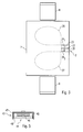
- Fig. 2 the first embodiment of the luminaire 1 according to the invention is shown in a view from above.
- the directional characteristic 16 meets a central region of the table 5 and thus ensures a homogeneous illumination of a corresponding workstation.
- the housing module 13 and the optical module 14 are square.
- four possible orientations of the optics module 14 within the housing module 13 are possible.
- the directional characteristic 16 shifts in each case by 90 °.
- a second embodiment of the luminaire 2 according to the invention is shown in a view from above.
- the lamp 2 has a foot 20, a horizontal support 22, a housing module 23 and two optical modules 24 1 , 2 4 2.
- the lamp 2 is arranged on a table 7.
- the table 7 has two separate workplaces. In front of each of these workstations is a chair 8, 9.
- the housing module 23 is here seen from above rectangular.
- the two optical modules 24 1 and 24 2 are arranged side by side.
- the orientations of the optical modules 24 1 , 24 2 are independently selectable.
- the optical modules 24 1 and 24 2 are arranged such that at each of the two jobs an optimal directional characteristic 26, 27 of the light emitted by the light 2 results.
- each of the optical modules 24 1 , 24 2 can be arranged again in four possible orientations within the housing module 23.
- a third embodiment of the luminaire 3 according to the invention is shown.
- the luminaire 3 is a floor lamp.
- the luminaire 3 has a foot 30, a vertical support 31, a horizontal support 32, a housing module 33 and an optical module 34.
- the housing module 33 here has a housing 37, a heat sink 35 and an LED module 36.
- the optical module 34 has a prism element 38 here.
- the housing module 33 is firmly connected to the horizontal support 32.
- the optical module 34 which consists only of the prism element 38 here, is detachably connected to the housing module 33. It can preferably be removed from the housing module 33 without tools and re-set in the housing module 33 in a changed orientation.
- the housing module 33 and the optical module 34 are here each made rectangular seen from above, four possible orientations are conceivable.
- the housing module 33 and the optics module 34 may also have other shapes. For example, 5-sided, 6-square, 7-square, 8-square or even round shapes are possible. In any case, however, the shapes must be at least in one axis be symmetrical to allow a twisted connection of the optical module 34 with the housing module 33 when changing the orientation.
- the optics module 34 may include a diffuser or a lens cluster or a reflector grid. Combinations of these components are possible.
- This first illustrated embodiment allows a very simple change in the directional characteristic of the radiated light. At the same time, however, it is limited in terms of achievable change in the directional characteristic.
- Fig. 5 shows an alternative embodiment of the housing module 43 and the optical module 44 as a fourth embodiment of the lamp according to the invention.
- the housing module 43 contains only one housing 47.
- the optical module 44 includes a prism element 48, a heat sink 45 and an LED module 46.
- the electrical connection of the LED module 46 thus likewise becomes separated from the rest of the lamp.
- the electrical connection is thus also designed such that it remains functional in a twisted in a further orientation assembly.
- the second variant shown allows a very strong change in the directional characteristic of the radiated light. However, it is more expensive because a detachable electrical connection is needed, which is independent of the orientation of the optical module 44 to the housing module 43 is functional.
- the invention is not limited to the illustrated embodiment. As already mentioned, various forms of the housing module and the optical module can be used. Also, multiple optical modules can be used within a housing module. In addition, the use of multiple housing modules and multiple optical modules is conceivable. It is also possible to use several LED modules within a housing module or optical module. All features described above or features shown in the figures can be combined with each other in any advantageous manner within the scope of the invention.
Landscapes
- Engineering & Computer Science (AREA)
- General Engineering & Computer Science (AREA)
- Non-Portable Lighting Devices Or Systems Thereof (AREA)
- Fastening Of Light Sources Or Lamp Holders (AREA)
Abstract
Description
- Die Erfindung betrifft eine Leuchte, bevorzugt eine Stehleuchte.
- Arbeitsplatzleuchten weisen üblicherweise eine symmetrische Richtcharakteristik des abgestrahlten Lichts auf. Dies führt dazu, dass der Bereich direkt unterhalb der Leuchte am stärksten beleuchtet ist. In der Praxis hat sich jedoch gezeigt, dass derartige Leuchten häufig am Rand eines Tisches aufgestellt werden. Dies führt zu einer in Richtung des zentralen Arbeitsplatzes stark abnehmenden Leuchtstärke. Der Rand des Tisches wird dabei am stärksten beleuchtet. So ergibt sich ein erhöhter Energiebedarf, wenn eine Mindestleuchtstärke im Zentrum des Arbeitsplatzes erreicht werden soll. Darüber hinaus führt dies zu einer ungleichmäßigen Beleuchtung, was ergonomischen Gesichtspunkten widerspricht.
- So zeigt die deutsche Offenlegungsschrift
DE 10 2011 000 716 A1 eine Arbeitsplatzleuchte mit symmetrischer Richtcharakteristik des abgestrahlten Lichts. - Der Erfindung liegt die Aufgabe zu Grunde, eine Leuchte zu schaffen, welche eine gleichmäßige und energiesparende Ausleuchtung bei flexiblem Aufstellort gewährleistet.
- Die Aufgabe wird erfindungsgemäß für die Vorrichtung durch die Merkmale des unabhängigen Anspruchs 1 gelöst. Vorteilhafte Weiterbildungen sind Gegenstand der hierauf rückbezogenen Unteransprüche.
- Eine erfindungsgemäße Leuchte verfügt über ein erstes Optikmodul und ein Gehäusemodul. Das erste Optikmodul ist lösbar mittels einer Halterung mit dem Gehäusemodul verbunden. Das erste Optikmodul und das Gehäusemodul sind derart ausgebildet, dass das erste Optikmodul zumindest in einer ersten Ausrichtung und in einer zweiten Ausrichtung mittels der Halterung mit dem Gehäusemodul verbindbar ist. Weiterhin sind sie derart ausgebildet, dass sich eine Richtcharakteristik von der Leuchte emittierten Lichts bei Verbindung des ersten Optikmoduls mit dem Gehäusemodul in der ersten Ausrichtung und in der zweiten Ausrichtung unterscheidet. So kann mit geringem Aufwand eine Veränderung der Richtcharakteristik erreicht werden.
- Vorzugsweise beinhaltet das erste Optikmodul einen Diffusor und/oder ein Prismenelement und/oder einen Linsencluster und/oder ein Reflektorraster. So kann die Richtcharakteristik sehr einfach eingestellt werden.
- Bevorzugt sind das erste Optikmodul und das Gehäusemodul derart ausgebildet, dass ein Trennen des ersten Optikmoduls von dem Gehäusemodul, eine Veränderung der Ausrichtung und ein Verbinden des ersten Optikmoduls mit dem Gehäusemodul werkzeuglos möglich sind. So kann mit besonders geringem Aufwand eine Anpassung der Richtcharakteristik erreicht werden.
- Das Gehäusemodul und das erste Optikmodul weisen bevorzugt im Wesentlichen vier-eckige Grundflächen auf. Das erste Optikmodul weist dann vier mögliche Ausrichtungen gegenüber dem Gehäusemodul auf. Die vier möglichen Ausrichtungen sind dann durch Drehen des ersten Optikmoduls gegenüber dem Gehäusemodul in Schritten von 90° erreichbar. So kann ein sehr geringer Herstellungsaufwand erreicht werden bzw. der Kunde ist selbst in der Lage, die Ausrichtung der Abstrahlcharakteristik zu ändern.
- Das Gehäusemodul und das erste Optikmodul weisen alternativ im Wesentlichen regelmäßige sechs-eckige Grundflächen auf. Das erste Optikmodul weist dann sechs mögliche Ausrichtungen gegenüber dem Gehäusemodul auf. Die sechs möglichen Ausrichtungen sind dann durch Drehen des ersten Optikmoduls gegenüber dem Gehäusemodul in Schritten von 60° erreichbar. So kann eine genauere Einstellbarkeit der Richtcharakteristik erreicht werden.
- Vorzugsweise weisen das Gehäusemodul und das erste Optikmodul im Wesentlichen regelmäßige X-eckige Grundflächen auf. Das erste Optikmodul weist dann X mögliche Ausrichtungen gegenüber dem Gehäusemodul auf. Die X möglichen Ausrichtungen sind dann durch Drehen des ersten Optikmoduls gegenüber dem Gehäusemodul in Schritten von 360°/X erreichbar. So ist eine besonders feine Einstellbarkeit der Richtcharakteristik möglich.
- Vorzugsweise weisen das Gehäusemodul und das erste Optikmodul im Wesentlichen runde Grundflächen auf. Das Gehäusemodul und das erste Optikmodul sind dann ausgebildet, um stufenlos gegeneinander verdreht zu werden. So ist durch das stufenlose Verdrehen eine beliebige Anzahl von Ausrichtungen des ersten Optikmoduls gegenüber dem Gehäusemodul erreichbar. Eine beliebige Verdrehung der Richtcharakteristik ist so erreichbar.
- Das erste Optikmodul ist bevorzugt zumindest in einer Achse symmetrisch aufgebaut. So ist eine einfache Gestaltung des Gehäusemoduls möglich.
- Das Gehäusemodul beinhaltet bevorzugt keine Lichtquelle. Das erste Optikmodul beinhaltet dann zumindest eine Lichtquelle. So wird eine in einem sehr großen Bereich einstellbare Richtcharakteristik erreicht.
- Alternativ beinhaltet das Gehäusemodul zumindest eine Lichtquelle. Das erste Optikmodul beinhaltet dann keine Lichtquelle. So kann ein sehr einfacher Aufbau erreicht werden.
- Das Gehäusemodul und/oder das erste Optikmodul beinhalten bevorzugt einen Kühlkörper. So wird eine lange Lebensdauer der Lichtquelle erreicht.
- Die Leuchte weist vorzugsweise zumindest ein zweites Optikmodul auf. Das Gehäusemodul und das erste Optikmodul und das zweite Optikmodul sind dann derart ausgebildet, dass das zweite Optikmodul zumindest in einer ersten Ausrichtung und in einer zweiten Ausrichtung mit dem Gehäusemodul verbindbar ist. Weiterhin sind sie derart ausgebildet, dass sich eine Richtcharakteristik von der Leuchte emittierten Lichts bei Verbindung des zweiten Optikmoduls mit dem Gehäusemodul in der ersten Ausrichtung und in der zweiten Ausrichtung unterscheidet. So kann für Doppelarbeitsplätze eine optimale Lichtverteilung erreicht werden.
- Bevorzugt sind das Gehäusemodul und das erste Optikmodul und das zweite Optikmodul derart ausgebildet, dass die Ausrichtungen des ersten Optikmoduls und des zweiten Optikmoduls unabhängig voneinander auswählbar sind. So kann die Richtcharakteristik des abgestrahlten Lichts sehr flexibel gewählt werden.
- Nachfolgend wird die Erfindung anhand der Zeichnung, in der ein vorteilhaftes Ausführungsbeispiel der Erfindung dargestellt ist, beispielhaft beschrieben. In der Zeichnung zeigen:
- Fig. 1
- ein erstes Ausführungsbeispiel der erfindungsgemäßen Leuchte in einer Seitenansicht;
- Fig. 2
- das erste Ausführungsbeispiel der erfindungsgemäßen Leuchte in einer Ansicht von oben;
- Fig. 3
- ein zweites Ausführungsbeispiel der erfindungsgemäßen Leuchte in einer Ansicht von oben;
- Fig. 4
- eine Detailansicht eines dritten Ausführungsbeispiels der erfindungsgemäßen Leuchte, und
- Fig. 5
- eine Detailansicht eines vierten Ausführungsbeispiels der erfindungsgemäßen Leuchte.
- Zunächst wird anhand der
Fig. 1 und Fig. 2 die generelle Problematik und der Aufbau und die Funktionsweise eines ersten Ausführungsbeispiels der erfindungsgemäßen Leuchte erläutert. Anhand vonFig. 3 wird auf Besonderheiten eines zweiten Ausführungsbeispiels der erfindungsgemäßen Leuchte eingegangen. InFig. 4 undFig. 5 wird auf den detaillierten Aufbau verschiedener Ausführungsbeispiele der erfindungsgemäßen Leuchte eingegangen. Identische Elemente wurden in ähnlichen Abbildungen zum Teil nicht wiederholt dargestellt und beschrieben. - In
Fig. 1 ist ein erstes Ausführungsbeispiel der erfindungsgemäßen Leuchte 1 dargestellt. Bei der hier dargestellten Leuchte 1 handelt es sich um eine Tischleuchte, welche auf einem Tisch 5 steht. Sämtliche der Erfindung zu Grunde liegenden Gedanken können ebenso bei einer auf dem Fußboden stehenden Stehleuchte umgesetzt werden. Neben dem Tisch 5 ist weiterhin ein Stuhl 6 angeordnet. - Die Leuchte 1 verfügt über einen Fuß 10, einen vertikalen Träger 11 und einen horizontalen Träger 12. Der Fuß 10 ruht dabei auf dem Tisch 5 und ist mit dem vertikalen Träger 11 verbunden. Dieser wiederum ist an seinem oberen Ende mit dem horizontalen Träger 12 verbunden. Am Ende des horizontalen Trägers 12 wiederum ist ein Gehäusemodul 13 angebracht. Mit dem Gehäusemodul 13 verbunden ist ein Optikmodul 14. Auf eine Darstellung der Stromversorgung der Leuchte 1 wurde hier verzichtet. Diese könnte beispielsweise durch ein Kabel von einer Steckdose zu dem Fuß 10 und durch die Träger 11 und 12 erfolgen. Auch ein Betrieb mit Batterien ist denkbar.
- Das Gehäusemodul 13 ist dabei fest mit dem horizontalen Träger 12 verbunden. Das Optikmodul 14 ist lösbar mittels einer Halterung mit dem Gehäusemodul 13 verbunden. Das Optikmodul 14 kann dabei in mehreren Ausrichtungen in das Gehäusemodul 13 eingesetzt werden. Vorzugsweise sind ein Entfernen des Optikmoduls 14, eine Veränderung der Ausrichtung und ein erneutes Verbinden des Optikmoduls 14 mit dem Gehäusemodul 13 werkzeuglos möglich.
- In
Fig. 2 ist das erste Ausführungsbeispiel der erfindungsgemäßen Leuchte 1 in einer Ansicht von oben dargestellt. Deutlich erkennbar ist hier eine Richtcharakteristik 16 des von der Leuchte 1 abgestrahlten Lichts. Wie hier ersichtlich, trifft die Richtcharakteristik 16 einen zentralen Bereich des Tisches 5 und sorgt so für eine homogene Ausleuchtung eines entsprechenden Arbeitsplatzes. - Darüber hinaus ist hier ersichtlich, dass das Gehäusemodul 13 und das Optikmodul 14 quadratisch sind. Somit sind vier mögliche Ausrichtungen des Optikmoduls 14 innerhalb des Gehäusemoduls 13 möglich. Bei jeder der vier möglichen Ausrichtungen verschiebt sich die Richtcharakteristik 16 entsprechend jeweils um 90°.
- In
Fig. 3 ist ein zweites Ausführungsbeispiel der erfindungsgemäßen Leuchte 2 in einer Ansicht von oben dargestellt. Die Leuchte 2 verfügt dabei über einen Fuß 20, einen horizontalen Träger 22, ein Gehäusemodul 23 und zwei Optikmodule 241, 242. Die Leuchte 2 ist auf einem Tisch 7 angeordnet. Der Tisch 7 weist zwei getrennte Arbeitsplätze auf. Vor jedem dieser Arbeitsplätze steht ein Stuhl 8, 9. - Das Gehäusemodul 23 ist hier von oben gesehen rechteckig ausgeführt. In dem einen Gehäusemodul 23 sind die zwei Optikmodule 241 und 242 nebeneinander angeordnet. Die Ausrichtungen der Optikmodule 241, 242 sind dabei unabhängig voneinander wählbar. Somit sind hier die Optikmodule 241 und 242 derart angeordnet, dass sich an jedem der beiden Arbeitsplätze eine optimale Richtcharakteristik 26, 27 des durch die Leuchte 2 abgestrahlten Lichts ergibt.
- Da hier das Gehäusemodul 23 eine rechteckige Form aufweist, welche zwei Optikmodulen 241, 242 nebeneinander Platz bietet, kann jedes der Optikmodule 241, 242 erneut in vier möglichen Ausrichtungen innerhalb des Gehäusemoduls 23 angeordnet werden.
- In
Fig. 4 ist ein drittes Ausführungsbeispiel der erfindungsgemäßen Leuchte 3 gezeigt. Bei der Leuchte 3 handelt es sich hier um eine Stehleuchte. Die Leuchte 3 verfügt über einen Fuß 30, einen vertikalen Träger 31, einen horizontalen Träger 32, ein Gehäusemodul 33 und ein Optikmodul 34. - Das Gehäusemodul 33 verfügt hier über ein Gehäuse 37, einen Kühlkörper 35 und ein LED-Modul 36. Das Optikmodul 34 verfügt hier über ein Prismenelement 38. Das Gehäusemodul 33 ist dabei fest mit dem horizontalen Träger 32 verbunden. Das Optikmodul 34, welches hier lediglich aus dem Prismenelement 38 besteht, ist lösbar mit dem Gehäusemodul 33 verbunden. Es kann vorzugsweise werkzeuglos aus dem Gehäusemodul 33 entnommen werden und in geänderter Ausrichtung erneut in das Gehäusemodul 33 eigesetzt werden.
- Da das Gehäusemodul 33 und das Optikmodul 34 hier jeweils von oben gesehen rechteckig ausgeführt sind, sind vier mögliche Ausrichtungen denkbar. Jedoch können das Gehäusemodul 33 und das Optikmodul 34 auch andere Formen aufweisen. So sind beispielsweise 5-eckige, 6-eckige, 7-eckige, 8-eckige oder auch runde Formen möglich. In jedem Fall müssen die Formen jedoch zumindest in einer Achse symmetrisch sein, um ein verdrehtes Verbinden des Optikmoduls 34 mit dem Gehäusemodul 33 bei Änderung der Ausrichtung zu ermöglichen.
- Anstatt eines Prismenelements 38 kann das Optikmodul 34 einen Diffusor oder einen Linsencluster oder ein Reflektorraster beinhalten. Auch Kombinationen dieser Bauelemente sind möglich.
- Diese erste dargestellte Ausgestaltung ermöglicht eine sehr einfache Änderung der Richtcharakteristik des abgestrahlten Lichts. Gleichzeitig ist sie jedoch hinsichtlich der erreichbaren Änderung der Richtcharakteristik eingeschränkt.
-
Fig. 5 zeigt eine alternative Ausgestaltung des Gehäusemoduls 43 und des Optikmoduls 44 als viertes Ausführungsbeispiel der erfindungsgemäßen Leuchte. Das Gehäusemodul 43 beinhaltet hier lediglich ein Gehäuse 47. Das Optikmodul 44 beinhaltet hier ein Prismenelement 48, einen Kühlkörper 45 und ein LED-Modul 46. Bei einem Trennen des Optikmoduls 44 von dem Gehäusemodul 43 wird somit ebenfalls die elektrische Verbindung des LED-Moduls 46 von der übrigen Leuchte getrennt. Die elektrische Verbindung ist somit ebenfalls derart ausgeführt, dass sie bei einer in einer weiteren Ausrichtung verdrehten Montage funktionsfähig bleibt. - Die zweite dargestellte Variante ermöglicht eine sehr starke Änderung der Richtcharakteristik des abgestrahlten Lichts. Sie ist jedoch aufwendiger, da eine lösbare elektrische Verbindung benötigt wird, welche unabhängig von der Ausrichtung des Optikmoduls 44 zu dem Gehäusemodul 43 funktionsfähig ist.
- Die Erfindung ist nicht auf das dargestellte Ausführungsbeispiel beschränkt. Wie bereits erwähnt, können unterschiedlichste Formen des Gehäusemoduls und des Optikmoduls eingesetzt werden. Auch können mehrere Optikmodule innerhalb eines Gehäusemoduls eingesetzt werden. Darüber hinaus ist auch die Verwendung mehrerer Gehäusemodule und mehrerer Optikmodule denkbar. Auch ein Einsatz mehrerer LED-Module innerhalb eines Gehäusemoduls oder Optikmoduls ist möglich. Alle vorstehend beschriebenen Merkmale oder in den Figuren gezeigten Merkmale sind im Rahmen der Erfindung beliebig vorteilhaft miteinander kombinierbar.
Claims (15)
- Leuchte (1, 2, 3) mit einem ersten Optikmodul (14, 241, 34, 44) und einem Gehäusemodul (13, 23, 33, 43),
wobei das erste Optikmodul (14, 241, 34, 44) lösbar mittels einer Halterung mit dem Gehäusemodul (13, 23, 33, 43) verbunden ist,
dadurch gekennzeichnet,
dass das erste Optikmodul (14, 241, 34, 44) und das Gehäusemodul (13, 23, 33, 43) derart ausgebildet sind,
dass das erste Optikmodul (14, 241, 34, 44) zumindest in einer ersten Ausrichtung und in einer zweiten Ausrichtung mittels der Halterung mit dem Gehäusemodul (13, 23, 33, 43) verbindbar ist, und
dass sich eine Richtcharakteristik (16) von der Leuchte (1, 2, 3) emittierten Lichts bei Verbindung des ersten Optikmoduls (14, 241, 34, 44) mit dem Gehäusemodul (13, 23, 33, 43) in der ersten Ausrichtung und in der zweiten Ausrichtung unterscheidet. - Leuchte nach Anspruch 1,
dadurch gekennzeichnet,
dass das erste Optikmodul (14, 241, 34, 44) einen Diffusor und/oder ein Prismenelement (38, 48) und/oder einen Linsencluster und/oder ein Reflektorraster beinhaltet. - Leuchte nach Anspruch 1 oder 2,
dadurch gekennzeichnet,
dass das erste Optikmodul (14, 241, 34, 44) und das Gehäusemodul (13, 23, 33, 43) derart ausgebildet sind, dass ein Trennen des ersten Optikmoduls (14, 241, 34, 44) von dem Gehäusemodul (13, 23, 33, 43), eine Veränderung der Ausrichtung und ein Verbinden des ersten Optikmoduls (14, 241, 34, 44) mit dem Gehäusemodul (13, 23, 33, 43) werkzeuglos möglich sind. - Leuchte nach einem der Ansprüche 1 bis 3,
dadurch gekennzeichnet,
dass das Gehäusemodul (13, 23, 33, 43) und das erste Optikmodul (14, 241, 34, 44) im Wesentlichen vier-eckige Grundflächen aufweisen,
dass das erste Optikmodul (14, 241, 34, 44) vier mögliche Ausrichtungen gegenüber dem Gehäusemodul (13, 23, 33, 43) aufweist, und
dass die vier möglichen Ausrichtungen durch Drehen des ersten Optikmoduls (14, 241, 34, 44) gegenüber dem Gehäusemodul (13, 23, 33, 43) in Schritten von 90° erreichbar sind. - Leuchte nach einem der Ansprüche 1 bis 3,
dadurch gekennzeichnet,
dass das Gehäusemodul und das erste Optikmodul im Wesentlichen regelmäßige sechs-eckige Grundflächen aufweisen,
dass das erste Optikmodul sechs mögliche Ausrichtungen gegenüber dem Gehäusemodul aufweist, und
dass die sechs möglichen Ausrichtungen durch Drehen des ersten Optikmoduls gegenüber dem Gehäusemodul in Schritten von 60° erreichbar sind. - Leuchte nach einem der Ansprüche 1 bis 3,
dadurch gekennzeichnet,
dass das Gehäusemodul (13, 23, 33, 43) und das erste Optikmodul (14, 241, 34, 44) im Wesentlichen regelmäßige X-eckige Grundflächen aufweisen,
dass das erste Optikmodul (14, 241, 34, 44) X mögliche Ausrichtungen gegenüber dem Gehäusemodul (13, 23, 33, 43) aufweist, und
dass die X möglichen Ausrichtungen durch Drehen des ersten Optikmoduls (14, 241, 34, 44) gegenüber dem Gehäusemodul (13, 23, 33, 43) in Schritten von 360°/X erreichbar sind. - Leuchte nach einem der Ansprüche 1 bis 3,
dadurch gekennzeichnet,
dass das Gehäusemodul und das erste Optikmodul im Wesentlichen runde Grundflächen aufweisen,
dass das Gehäusemodul und das erste Optikmodul ausgebildet sind, um stufenlos gegeneinander verdreht zu werden, und
dass durch das stufenlose Verdrehen eine beliebige Anzahl von Ausrichtungen des ersten Optikmoduls gegenüber dem Gehäusemodul erreichbar ist. - Leuchte nach einem der Ansprüche 1 bis 7,
dadurch gekennzeichnet,
dass das erste Optikmodul (14, 241, 34, 44) zumindest in einer Achse symmetrisch aufgebaut ist. - Leuchte nach einem der Ansprüche 1 bis 8,
dadurch gekennzeichnet,
dass das Gehäusemodul (13, 23, 33) keine Lichtquelle beinhaltet, und
dass das erste Optikmodul (44) zumindest eine Lichtquelle (46) beinhaltet. - Leuchte nach einem der Ansprüche 1 bis 8,
dadurch gekennzeichnet,
dass das Gehäusemodul (43) zumindest eine Lichtquelle (36) beinhaltet, und
dass das erste Optikmodul (14, 241, 34) keine Lichtquelle beinhaltet. - Leuchte nach einem der Ansprüche 1 bis 10,
dadurch gekennzeichnet,
dass das Gehäusemodul (13, 23, 33, 43) und/oder das erste Optikmodul (14, 241, 34, 44) einen Kühlkörper (35, 45) beinhalten. - Leuchte nach einem der Ansprüche 1 bis 11,
dadurch gekennzeichnet,
dass die Leuchte (3) eine Stehleuchte ist. - Leuchte nach einem der Ansprüche 1 bis 12,
dadurch gekennzeichnet,
dass die Leuchte (1, 2) eine Tischleuchte ist. - Leuchte nach einem der Ansprüche 1 bis 13,
dadurch gekennzeichnet,
dass die Leuchte (2) zumindest ein zweites Optikmodul (242) aufweist,
dass das Gehäusemodul (23) und das erste Optikmodul (241) und das zweite Optikmodul (242) derart ausgebildet sind,
dass das zweite Optikmodul (242) zumindest in einer ersten Ausrichtung und in einer zweiten Ausrichtung mit dem Gehäusemodul (23) verbindbar ist, und
dass sich eine Richtcharakteristik (26, 27) von der Leuchte (2) emittierten Lichts bei Verbindung des zweiten Optikmoduls (242) mit dem Gehäusemodul (23) in der ersten Ausrichtung und in der zweiten Ausrichtung unterscheidet. - Leuchte nach Anspruch 14,
dadurch gekennzeichnet,
dass das Gehäusemodul (23) und das erste Optikmodul (241) und das zweite Optikmodul (242) derart ausgebildet sind, dass die Ausrichtungen des ersten Optikmoduls (241) und des zweiten Optikmoduls (242) unabhängig voneinander auswählbar sind.
Applications Claiming Priority (1)
| Application Number | Priority Date | Filing Date | Title |
|---|---|---|---|
| DE202012104136.7U DE202012104136U1 (de) | 2012-10-29 | 2012-10-29 | Leuchte mit verdrehbarer Optikeinheit |
Publications (2)
| Publication Number | Publication Date |
|---|---|
| EP2725287A2 true EP2725287A2 (de) | 2014-04-30 |
| EP2725287A3 EP2725287A3 (de) | 2015-10-14 |
Family
ID=49509964
Family Applications (1)
| Application Number | Title | Priority Date | Filing Date |
|---|---|---|---|
| EP13190473.2A Withdrawn EP2725287A3 (de) | 2012-10-29 | 2013-10-28 | Leuchte mit verdrehbarer Optikeinheit |
Country Status (2)
| Country | Link |
|---|---|
| EP (1) | EP2725287A3 (de) |
| DE (1) | DE202012104136U1 (de) |
Families Citing this family (1)
| Publication number | Priority date | Publication date | Assignee | Title |
|---|---|---|---|---|
| DE202016105051U1 (de) * | 2016-09-12 | 2016-09-29 | Ridi Leuchten Gmbh | Standleuchte |
Citations (1)
| Publication number | Priority date | Publication date | Assignee | Title |
|---|---|---|---|---|
| DE102011000716A1 (de) | 2011-02-07 | 2012-08-09 | Novaled Ag | Leuchte |
Family Cites Families (11)
| Publication number | Priority date | Publication date | Assignee | Title |
|---|---|---|---|---|
| JPS5947842B2 (ja) * | 1976-06-15 | 1984-11-21 | 光伸 松尾 | 照明装置 |
| DE29617755U1 (de) * | 1996-10-12 | 1997-01-02 | Ansorg GmbH, 45481 Mülheim | Stehleuchte |
| EP1143194A1 (de) * | 2000-04-06 | 2001-10-10 | Belux AG | Stehleuchte |
| US7488084B2 (en) * | 2004-10-29 | 2009-02-10 | Pentair Water Pool And Spa, Inc. | Selectable beam lens for underwater light |
| DE102007044065A1 (de) * | 2007-09-14 | 2009-03-19 | Trilux Gmbh & Co. Kg | Leuchte mit drehbarem Leuchtenkopf |
| US7665864B2 (en) * | 2008-03-20 | 2010-02-23 | Fu Zhun Precision Industry (Shen Zhen) Co., Ltd. | LED lamp assembly |
| WO2010097733A1 (en) * | 2009-02-24 | 2010-09-02 | Koninklijke Philips Electronics N.V. | Directable magnetic mount for light emitter, a light source, a base and an illumination system |
| CH701108A2 (de) * | 2009-05-19 | 2010-11-30 | Lukas Giger | Leuchtvorrichtung. |
| IT1397380B1 (it) * | 2010-01-08 | 2013-01-10 | Khatod Optoelectronic Srl | Sistema di illuminazione e metodo di montaggio dello stesso. |
| DE102010044353A1 (de) * | 2010-09-03 | 2012-03-08 | Herbert Waldmann Gmbh & Co. Kg | Steh- oder Tischleuchte |
| DE102011012129A1 (de) * | 2011-02-23 | 2012-08-23 | Bartenbach Holding Gmbh | Beleuchtungsvorrichtung |
-
2012
- 2012-10-29 DE DE202012104136.7U patent/DE202012104136U1/de not_active Expired - Lifetime
-
2013
- 2013-10-28 EP EP13190473.2A patent/EP2725287A3/de not_active Withdrawn
Patent Citations (1)
| Publication number | Priority date | Publication date | Assignee | Title |
|---|---|---|---|---|
| DE102011000716A1 (de) | 2011-02-07 | 2012-08-09 | Novaled Ag | Leuchte |
Also Published As
| Publication number | Publication date |
|---|---|
| DE202012104136U1 (de) | 2014-02-04 |
| EP2725287A3 (de) | 2015-10-14 |
Similar Documents
| Publication | Publication Date | Title |
|---|---|---|
| EP2436974B1 (de) | LED-Leuchte | |
| EP1239214B1 (de) | Anzeigeleuchtensäule | |
| DE102015202653B4 (de) | Opto-mechanisch einstellbare und erweiterbare Beleuchtungsvorrichtungen | |
| EP3014169A1 (de) | Leuchte zur verwendung in einem lichtbandsystem sowie lichtbandsystem | |
| WO2015132225A1 (de) | Leuchte mit trägerelement und lösbar befestigbarem leuchtmodul | |
| EP2986894B1 (de) | Leiterplatte für eine leuchte | |
| WO2012159744A2 (de) | Leuchte insbesondere strassenleuchte mit leds | |
| DE102016120256A1 (de) | Beleuchtungsvorrichtung mit variabler lichtverteilung | |
| EP3426975B1 (de) | Leuchte zur gleichmässigen ausleuchtung | |
| DE202012104136U1 (de) | Leuchte mit verdrehbarer Optikeinheit | |
| DE202021101788U1 (de) | Arbeitslampe | |
| DE102015202652A1 (de) | Opto-mechanisch einstellbare und erweiterbare Lichtplatten | |
| DE202015007928U1 (de) | Elektrisches Werkzeug mit Beleuchtungsfunktion | |
| EP2986899B1 (de) | Led-modul sowie anordnung zur lichtabgabe | |
| DE102012221454B4 (de) | Leuchte mit einem Leuchtengehäuse, das ein Profilelement umfasst | |
| EP2138763B1 (de) | Strahler und Stromschienensystem mit einem solchen Strahler | |
| DE102011110580A1 (de) | Leuchte, insbesondere Straßenleuchte mit LEDs | |
| DE102024117699B3 (de) | Arbeitsleuchte mit abnehmbarem Diffusor | |
| DE102011102406A1 (de) | Leuchte mit LEDs | |
| EP3446031B1 (de) | Schaltschrankleuchte mit verstellbarer leuchtmittelplatine | |
| DE102017109135B3 (de) | Beleuchtungseinrichtung für eine Unterputzinstallationsdose mit einer verschwenkbaren und/oder verdrehbaren kugelförmigen Leuchte, die durch zwei Clipselemente befestigt ist | |
| DE202007005958U1 (de) | Lampenanordnung | |
| EP2629004B1 (de) | Einbauleuchte für den Außenbereich, insbesondere zur Montage in einem Fensterrahmenprofil | |
| DE102013104150B4 (de) | Leuchtmittelhalterung und Verfahren zu deren Montage | |
| AT18591U1 (de) | Leuchte |
Legal Events
| Date | Code | Title | Description |
|---|---|---|---|
| PUAI | Public reference made under article 153(3) epc to a published international application that has entered the european phase |
Free format text: ORIGINAL CODE: 0009012 |
|
| 17P | Request for examination filed |
Effective date: 20131028 |
|
| AK | Designated contracting states |
Kind code of ref document: A2 Designated state(s): AL AT BE BG CH CY CZ DE DK EE ES FI FR GB GR HR HU IE IS IT LI LT LU LV MC MK MT NL NO PL PT RO RS SE SI SK SM TR |
|
| AX | Request for extension of the european patent |
Extension state: BA ME |
|
| PUAL | Search report despatched |
Free format text: ORIGINAL CODE: 0009013 |
|
| AK | Designated contracting states |
Kind code of ref document: A3 Designated state(s): AL AT BE BG CH CY CZ DE DK EE ES FI FR GB GR HR HU IE IS IT LI LT LU LV MC MK MT NL NO PL PT RO RS SE SI SK SM TR |
|
| AX | Request for extension of the european patent |
Extension state: BA ME |
|
| RIC1 | Information provided on ipc code assigned before grant |
Ipc: F21V 17/02 20060101ALI20150907BHEP Ipc: F21Y 101/02 20060101ALN20150907BHEP Ipc: F21V 5/02 20060101ALI20150907BHEP Ipc: F21V 7/00 20060101ALI20150907BHEP Ipc: F21S 6/00 20060101AFI20150907BHEP Ipc: F21V 5/00 20150101ALI20150907BHEP Ipc: F21V 14/06 20060101ALI20150907BHEP Ipc: F21W 131/402 20060101ALN20150907BHEP |
|
| STAA | Information on the status of an ep patent application or granted ep patent |
Free format text: STATUS: THE APPLICATION IS DEEMED TO BE WITHDRAWN |
|
| 18D | Application deemed to be withdrawn |
Effective date: 20160415 |