EP2725236B1 - Unité télescopique avec fonction supplémentaire - Google Patents
Unité télescopique avec fonction supplémentaire Download PDFInfo
- Publication number
- EP2725236B1 EP2725236B1 EP13075064.9A EP13075064A EP2725236B1 EP 2725236 B1 EP2725236 B1 EP 2725236B1 EP 13075064 A EP13075064 A EP 13075064A EP 2725236 B1 EP2725236 B1 EP 2725236B1
- Authority
- EP
- European Patent Office
- Prior art keywords
- hydraulic
- telescopic
- piston rod
- pressure
- hydraulic cylinder
- Prior art date
- Legal status (The legal status is an assumption and is not a legal conclusion. Google has not performed a legal analysis and makes no representation as to the accuracy of the status listed.)
- Active
Links
- 239000000872 buffer Substances 0.000 description 22
- 239000003921 oil Substances 0.000 description 18
- 241000657952 Elderberry carlavirus E Species 0.000 description 8
- 206010042602 Supraventricular extrasystoles Diseases 0.000 description 8
- 230000015654 memory Effects 0.000 description 7
- 238000010586 diagram Methods 0.000 description 6
- 238000000034 method Methods 0.000 description 3
- 239000003795 chemical substances by application Substances 0.000 description 2
- 230000006870 function Effects 0.000 description 2
- 238000012432 intermediate storage Methods 0.000 description 2
- 230000001105 regulatory effect Effects 0.000 description 2
- 230000003068 static effect Effects 0.000 description 2
- 238000003860 storage Methods 0.000 description 2
- 238000013459 approach Methods 0.000 description 1
- 230000005540 biological transmission Effects 0.000 description 1
- 239000012530 fluid Substances 0.000 description 1
- 239000010720 hydraulic oil Substances 0.000 description 1
- 238000010992 reflux Methods 0.000 description 1
- 230000002123 temporal effect Effects 0.000 description 1
Images


Classifications
-
- F—MECHANICAL ENGINEERING; LIGHTING; HEATING; WEAPONS; BLASTING
- F15—FLUID-PRESSURE ACTUATORS; HYDRAULICS OR PNEUMATICS IN GENERAL
- F15B—SYSTEMS ACTING BY MEANS OF FLUIDS IN GENERAL; FLUID-PRESSURE ACTUATORS, e.g. SERVOMOTORS; DETAILS OF FLUID-PRESSURE SYSTEMS, NOT OTHERWISE PROVIDED FOR
- F15B1/00—Installations or systems with accumulators; Supply reservoir or sump assemblies
- F15B1/02—Installations or systems with accumulators
- F15B1/027—Installations or systems with accumulators having accumulator charging devices
- F15B1/033—Installations or systems with accumulators having accumulator charging devices with electrical control means
-
- F—MECHANICAL ENGINEERING; LIGHTING; HEATING; WEAPONS; BLASTING
- F15—FLUID-PRESSURE ACTUATORS; HYDRAULICS OR PNEUMATICS IN GENERAL
- F15B—SYSTEMS ACTING BY MEANS OF FLUIDS IN GENERAL; FLUID-PRESSURE ACTUATORS, e.g. SERVOMOTORS; DETAILS OF FLUID-PRESSURE SYSTEMS, NOT OTHERWISE PROVIDED FOR
- F15B1/00—Installations or systems with accumulators; Supply reservoir or sump assemblies
- F15B1/02—Installations or systems with accumulators
- F15B1/024—Installations or systems with accumulators used as a supplementary power source, e.g. to store energy in idle periods to balance pump load
-
- F—MECHANICAL ENGINEERING; LIGHTING; HEATING; WEAPONS; BLASTING
- F15—FLUID-PRESSURE ACTUATORS; HYDRAULICS OR PNEUMATICS IN GENERAL
- F15B—SYSTEMS ACTING BY MEANS OF FLUIDS IN GENERAL; FLUID-PRESSURE ACTUATORS, e.g. SERVOMOTORS; DETAILS OF FLUID-PRESSURE SYSTEMS, NOT OTHERWISE PROVIDED FOR
- F15B1/00—Installations or systems with accumulators; Supply reservoir or sump assemblies
- F15B1/26—Supply reservoir or sump assemblies
-
- F—MECHANICAL ENGINEERING; LIGHTING; HEATING; WEAPONS; BLASTING
- F15—FLUID-PRESSURE ACTUATORS; HYDRAULICS OR PNEUMATICS IN GENERAL
- F15B—SYSTEMS ACTING BY MEANS OF FLUIDS IN GENERAL; FLUID-PRESSURE ACTUATORS, e.g. SERVOMOTORS; DETAILS OF FLUID-PRESSURE SYSTEMS, NOT OTHERWISE PROVIDED FOR
- F15B15/00—Fluid-actuated devices for displacing a member from one position to another; Gearing associated therewith
- F15B15/08—Characterised by the construction of the motor unit
- F15B15/14—Characterised by the construction of the motor unit of the straight-cylinder type
- F15B15/149—Fluid interconnections, e.g. fluid connectors, passages
-
- F—MECHANICAL ENGINEERING; LIGHTING; HEATING; WEAPONS; BLASTING
- F15—FLUID-PRESSURE ACTUATORS; HYDRAULICS OR PNEUMATICS IN GENERAL
- F15B—SYSTEMS ACTING BY MEANS OF FLUIDS IN GENERAL; FLUID-PRESSURE ACTUATORS, e.g. SERVOMOTORS; DETAILS OF FLUID-PRESSURE SYSTEMS, NOT OTHERWISE PROVIDED FOR
- F15B15/00—Fluid-actuated devices for displacing a member from one position to another; Gearing associated therewith
- F15B15/08—Characterised by the construction of the motor unit
- F15B15/14—Characterised by the construction of the motor unit of the straight-cylinder type
- F15B15/16—Characterised by the construction of the motor unit of the straight-cylinder type of the telescopic type
-
- F—MECHANICAL ENGINEERING; LIGHTING; HEATING; WEAPONS; BLASTING
- F15—FLUID-PRESSURE ACTUATORS; HYDRAULICS OR PNEUMATICS IN GENERAL
- F15B—SYSTEMS ACTING BY MEANS OF FLUIDS IN GENERAL; FLUID-PRESSURE ACTUATORS, e.g. SERVOMOTORS; DETAILS OF FLUID-PRESSURE SYSTEMS, NOT OTHERWISE PROVIDED FOR
- F15B2211/00—Circuits for servomotor systems
- F15B2211/60—Circuit components or control therefor
Definitions
- the present invention relates to a telescoping unit for telescoping means arranged on machines, comprising at least one telescopic hydraulic cylinder and at least one further hydraulic system (18), wherein the telescopic hydraulic cylinder (11) at least one in the cylinder chamber of the telescopic hydraulic cylinder arranged axially movable and connected to a piston rod piston, wherein the bottom side of the Teleskophydraulikzylinders is fixed to a bearing associated with the machine and at the exposed end of the piston rod, the at least one further hydraulic system is arranged, which is acted upon by a hydraulic medium with hydraulic energy wherein by placing the piston in the telescopic hydraulic cylinder, the hydraulic energy , Derived by the change in the operating condition and the resulting hydraulic pressure difference of the hydraulic medium in at least a first buffer and ges is accumulated, so as to pressurize the hydraulic system with the hydraulic energy from the first buffer in a case of need and wherein after consumption, the hydraulic medium stored in the hydraulic medium, the hydraulic medium is passed from the hydraulic system
- a mobile crane with telescopic boom with small counterweight can lift large loads, the boom must be as small as possible. Especially with larger working radii, it is necessary to keep the weight of the outrigger parts projecting beyond the support base as small as possible. Even when transporting a mobile crane, it is cheaper if the lowest possible weight has to be moved.
- the SVE is located at the exposed end of the telescopic hydraulic cylinder.
- the hydraulic energy is therefore also needed at this point, so that the boxes can be unlocked or locked.
- the disadvantage here is that exactly this point is driven back and forth with the telescopic hydraulic cylinder.
- the SVE is not directly accessible for hydraulic lines.
- the publication DE 10 2009 048 763 A1 also proposes as another way of supplying additional consumers to a telescopic cylinder for telescopic shots of a mobile crane with pressurized oil, to connect the additional consumer with at least one cylinder chamber of the telescopic cylinder and over here with pressurized oil.
- the additional consumers are connected via buffer and non-return valves both on the high-pressure side and on the low-pressure side with the telescoping cylinder and there with a cylinder tube of the telescoping cylinder.
- the consumers move with the telescoping cylinder.
- the hydraulic system, the control unit, as well as the first and second latches along with supply and return lines and check valves are designed to be movable together with the telescopic hydraulic cylinder.
- control unit and the first and second latches are arranged together with supply and return lines and check valves at the exposed end of the telescopic hydraulic cylinder and thus at the exposed end of the piston rod.
- pressures in the first and second latches are measured with pressure transducers and the measured pressure data are processed by a computer or sent directly to a control unit, the control unit causes the first latches to be automatically charged with the hydraulic medium becomes as soon as the pressure of the hydraulic medium in the telescopic hydraulic cylinder is higher than the pressure of the hydraulic medium in the first intermediate storage and, that the second buffer automatically discharged from the hydraulic medium when the pressure of the hydraulic medium in the telescopic hydraulic cylinder is smaller than the pressure of the hydraulic medium in the second buffer
- the buffers act as storage tanks, which buffer the high and low pressures in the hydraulic system.
- the process of loading and unloading the buffer can, depending on the version, even occur at the same time.
- the telescoping unit In the telescoping unit according to the invention, it is provided to connect at least two buffer stores, one each for the high pressure and one for the low pressure, which are in operative connection with the hydraulic system (for example an SVE) with the telescoping unit hydraulically.
- the number of buffers should not be limited to this.
- the supply of hydraulic power to the hydraulic system is ensured by the intermediate storage.
- the latches may be formed here as a bladder accumulator or piston accumulator or spring accumulator.
- the memory for the high pressure and for the different low pressure to be connected via check valves directly to the telescopic hydraulic cylinder.
- the first buffer for the high pressure is automatically filled, or pressurized via the hydraulic medium, that is charged with hydraulic energy when the hydraulic pressure in the bottom space of the telescopic hydraulic cylinder is higher than the pressure in the first intermediate store itself. This can be the case, for example, during telescoping, under static load or during extension of the telescopic hydraulic cylinder in the bolted and secured state until it stops.
- the second buffer is automatically discharged from the hydraulic medium as soon as the pressure of the hydraulic medium in the telescopic hydraulic cylinder is smaller than the pressure of the hydraulic medium in the second Buffer. This may for example be the case when the bottom-side valve of the telescopic hydraulic cylinder is opened (ie, the friction is greater than the static load) or the telescopic hydraulic cylinder is retracted in the bolted and secured state to the stop.
- the pressures in the buffers can be measured with pressure transducers and processed in a controller.
- control unit and / or the computer controls the telescoping unit as a function of the pressure data determined and sent to it by the pressure transducers in order to load or load the buffer memories with hydraulic energy by changing the driving condition discharged.
- the controller controls the hydraulic system via the pressure transducer to pressurize the hydraulic system with hydraulic energy as soon as the controller determines in the first latch for the placement of the hydraulic system insufficient amount of hydraulic energy.
- the pressure transducers are designed so that they can convert the pressure of the hydraulic medium into a proportional electrical signal.
- the supply of the hydraulic system with the hydraulic medium via the bottom side by the piston rod of the telescopic hydraulic cylinder in a hydraulic two-way single-space circuit in another embodiment, the supply of the hydraulic system with the hydraulic medium via the bottom side by the piston rod of the telescopic hydraulic cylinder in a hydraulic two-way single-space circuit.
- the hydraulic system is connected to the piston rod of the telescopic hydraulic cylinder and the return oil only in the Bottom side can be passed. Also, the return oil could only be directed into the piston rod side.
- the oil supply for the hydraulic system can be done via the piston rod and bottom side of the telescopic hydraulic cylinder in a hydraulic three-way two-space circuit, the hydraulic system is connected to the piston rod of the Teleskophydraulikzylinders and removed the pressure oil only from the rod side becomes.
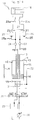
- the telescoping unit 10 consists essentially of at least one telescopic hydraulic cylinder 11 and at least one axially movable in the cylinder tube 12 of the telescopic hydraulic cylinder 11 and connected to a piston rod 13 piston 14.
- the bottom side 15 of the telescopic hydraulic cylinder 11 is at one of a machine or a part the machine (not shown) associated bearing (not shown) attached.
- At least one hydraulic system 18 is assigned to the free end of the telescoping unit 10.
- the hydraulic system 18 is formed in this embodiment as SVE.
- the hydraulic system 18 may be configured to install / remove implements.
- the bolting and Entbolzen of equipment for example, for turning, closing and opening of devices such as pliers, grippers, loading troughs and lifts, are conceivable.
- a hydraulic medium acted upon by hydraulic energy and forwarded to the hydraulic system 18.
- the hydraulic system 18 is, as in Fig. 1 shown connected to the piston rod side 16 of the telescopic hydraulic cylinder 11 via a line 19.
- the line 19 has a fork 20, which divides the line 19 into a feed line 21 and a return line 22. So that the hydraulic medium can flow in each case only in a predetermined direction in the feed line 21 and the return line 22, correspondingly designed valves 23 and 24 are provided.
- the valves 23 and 24 are formed in this embodiment as check valves.
- the check valve 23 prevents the unwanted reflux of the hydraulic medium from the supply line 21 back to the piston rod side 16 of the telescopic hydraulic cylinder 11.
- the supply line 21 is associated with a bypass 25 which is connected to a first latch 26.
- the buffer 26 is designed as a bladder accumulator in this embodiment.
- the supply line 21 is connected to a control unit 27.
- the control unit 27 is in turn connected to the hydraulic system 18 via the supply line 21a.
- the Control unit 27 detects and regulates the need for hydraulic energy and provides it to the hydraulic system 18, if necessary, from the buffer 26 is available.
- the "relaxed" hydraulic medium from the hydraulic system 18 is now directed into a return line 22a.
- the return flow of the hydraulic medium is regulated by the control unit 27 connected to the return line 22a.
- the expanded hydraulic medium is passed via a bypass 25a into a second intermediate store 28 with a hydraulic medium having a lower pressure than the first intermediate store 26 and stored therebetween.
- a backflow of the hydraulic medium by the control unit 27 and then further into the hydraulic system 18 is avoided by the control unit 27.
- the check valve 24 is connected to the supply line 19, from where the hydraulic medium is pushed back into the cylinder chamber 12 at the appropriate opportunity.
- the hydraulic system 18, the control unit 27, and the latches 26, 28 together with the supply and return lines 19, 21, 21 a and 22, 22 a and the check valves 23 and 24 are formed movable together with the telescopic hydraulic cylinder 11.
- the hydraulic system 18 can be stored floating.
- the hydraulic medium is stored in a reservoir 29, from where it is provided by means of a hydraulic pump 30 via adjusting and control means 31 to the telescopic hydraulic cylinder 11.
- the Fig. 1 shows the telescoping unit 10 according to the invention in an embodiment in which the supply of the hydraulic system 18 with a hydraulic medium through the piston rod 13 with the bottom side of the telescopic hydraulic cylinder 11, with a hydraulic two-way one-space circuit.
- the hydraulic medium can be passed from the piston rod side 16 via a return line 32 to the adjusting and control means 31, from where it is pumped back into the reservoir 29.
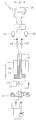
- the Fig. 2 also shows an embodiment of the telescoping unit 10 according to the invention.
- the hydraulic system 18 is supplied with a hydraulic medium, as in Fig. 1 represented, also by the piston rod 13 to the bottom and rod side 15 and 16 of the telescopic hydraulic cylinder 11.
- the embodiment is designed as a two-way hydraulic two-space circuit.
- the check valves 23, 24 and 37, 38 are replaced by electric seat valves. These electric seat valves are then controlled by an electrical control, taking into account the pressure transducer signals of the pressure transducer 42, 42 a.
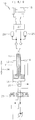
- the Fig . 3 also shows an embodiment of the telecopying unit 10 according to the invention.
- the supply of the hydraulic system 18 with a hydraulic medium takes place, as in the Fig. 2 represented, also by the piston rod 13 to the bottom and rod side 15, 16 of the telescopic hydraulic cylinder 11.
- This embodiment is designed as a hydraulic four-way two-space circuit.
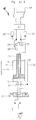
- the Fig. 4 also shows an embodiment of the telescoping unit 10 according to the invention.
- the hydraulic system 18 is supplied with a hydraulic medium, as in FIG Fig. 2 also represented by the piston rod 13 to the bottom and rod side 15, 16 of the telescopic hydraulic cylinder 11.
- the embodiment is, as in Fig. 2 , designed as a hydraulic two-way two-space circuit. But unlike Fig. 2 Here are the charge-discharge lines connected to the piston rod 13 rotated. Thus, the hydraulic medium is pressed from the piston rod side 16 in the memory 26 and from the memory 28, the return takes place in the bottom side 15th
- the Fig. 5 shows the telescoping unit 10 according to the invention in a further embodiment, in which the supply of the hydraulic system 18 with a hydraulic medium, by the piston rod 13 to the piston rod side 16 of the telescopic hydraulic cylinder 11, with a "two-way single-space circuit".
- the Fig. 6 shows the telescoping unit 10 according to the invention in a further embodiment in the supply of the hydraulic system 18 with a hydraulic medium, analog Fig. 3 , So by the piston rod 13, takes place.
- the medium from the reservoir 26 can only flow back into the bottom side 15 via the valve 24.
- Valve 38 is not installed. This is also a "three-way two-space circuit.
- the Fig. 7 shows the telescoping unit 10 according to the invention in a further embodiment in the supply of the hydraulic system 18 with a hydraulic medium, analog Fig. 3 , he follows.
- the medium from the reservoir 26 can only flow back into the rod side 16 via the valve 38.
- valve 24 is not installed. It is also a "three-way two-space circuit".
- the Fig. 8 shows the telescoping unit 10 according to the invention in a further embodiment in the supply of the hydraulic system 18 with a hydraulic medium, analog Fig. 3 , he follows.
- the reservoir 26 is pressurized only via the valve 23 from the bottom side 15.
- valve 37 is not installed. It is also a "three-way two-space circuit".
- the Fig. 9 shows the telescoping unit 10 according to the invention in a further embodiment in the supply of the hydraulic system 18 with a hydraulic medium, analog Fig. 3 , he follows.
- the pressure supply of the memory 26 takes place only via the valve 37 and only from the rod side 16. There is no charging connection to the bottom side 15. Again, there is a "three-way two-space circuit".
Claims (19)
- Unité télescopique (10) destiné à télescoper des moyens disposés au niveau de machines, l'unité télescopique comprenant au moins un cylindre hydraulique télescopique (11) et au moins un autre système hydraulique (18), le cylindre hydraulique télescopique (11) comprenant au moins un piston (14) disposé de manière à pouvoir se déplacer axialement dans la chambre du cylindre hydraulique télescopique (11) et relié à une tige de piston (13), un côté fond (15) du cylindre hydraulique télescopique (11) étant conçu de manière à pouvoir être fixé à un palier associé à la machine et l'au moins un autre système hydraulique (18), qui est alimenté en énergie hydraulique par le biais d'un milieu hydraulique, étant disposé à l'extrémité exposée de la tige de piston (13), le réglage du piston (14) dans le cylindre hydraulique télescopique (11) permettant de stocker l'énergie hydraulique, qui provient du changement d'état de fonctionnement et de la différence de pression du milieu hydraulique qui en résulte, dans au moins un premier accumulateur intermédiaire (26, 39) pour alimenter le système hydraulique (18) avec l'énergie hydraulique provenant du premier accumulateur intermédiaire (26, 39) en cas de besoin et, après consommation de l'énergie hydraulique stockée dans le milieu hydraulique, le milieu hydraulique passant du système hydraulique (18) dans au moins un deuxième accumulateur intermédiaire (28, 40) puis passant de nouveau dans le cylindre hydraulique télescopique (11) où il est à nouveau alimenté en énergie hydraulique ou amené à un circuit hydraulique primaire de l'unité télescopique (10), l'alimentation du système hydraulique (18) avec le milieu hydraulique étant effectuée par la tige de piston (13) du cylindre hydraulique télescopique (11).
- Unité télescopique selon la revendication 1, caractérisée en ce que les pressions dans les premier et deuxième accumulateurs intermédiaires (26, 39, 28, 40) sont mesurées avec des capteurs de pression (42, 42a) et les données de pression mesurées sont traitées par un ordinateur ou envoyées directement à une unité de commande (27), le système hydraulique (18), l'unité de commande (27) et les premier et deuxième accumulateurs intermédiaires (26, 28, 39, 40), ainsi que des conduites d'alimentation et de retour (19, 21, 21a, 22, 22a) et des clapets anti-retour (23, 24) étant conçus de manière à pouvoir être déplacés conjointement avec le cylindre hydraulique télescopique (11).
- Unité télescopique selon la revendication 1 ou 2, caractérisée en ce que les pressions dans les premier et deuxième accumulateurs intermédiaires (26, 39, 28, 40) sont mesurées par des capteurs à pression (42, 42a) et les données de pression mesurées sont traitées par un ordinateur ou envoyées directement à une unité de commande (27), l'unité de commande (27) et les premier et deuxième accumulateurs intermédiaires (26, 28, 39, 40) ainsi que des conduites d'alimentation et de retour (19, 21, 21a, 22, 22a) et des clapets anti-retour (23, 24) étant disposés à l'extrémité exposée du cylindre hydraulique télescopique (11) et donc à l'extrémité exposée de la tige de piston (13).
- Unité télescopique selon l'une des revendications 1 à 3, caractérisée en ce que les pressions dans les premier et deuxième accumulateurs intermédiaires (26, 39, 28, 40) sont mesurées avec des capteurs de pression (42, 42a) et les données de pression mesurées sont traitées par un ordinateur ou envoyées directement à une unité de commande (27), l'unité de commande (27) agissant de manière à ce que le premier accumulateur intermédiaire (26, 39) soit chargé automatiquement avec le milieu hydraulique dès que la pression du milieu hydraulique dans le cylindre hydraulique télescopique (11) est supérieure à la pression du milieu hydraulique dans le premier accumulateur intermédiaire (26, 39) et de manière à ce que le deuxième accumulateur intermédiaire (28, 40) est automatiquement déchargé du milieu hydraulique dès que la pression du milieu hydraulique dans le cylindre hydraulique télescopique (11) est inférieure à la pression du milieu hydraulique dans le deuxième accumulateur intermédiaire (28, 40).
- Unité télescopique selon l'une des revendications 1 à 4, caractérisée en ce que les première et deuxième accumulateurs intermédiaires (26, 39, 28, 40) sont conçues comme des accumulateurs à vessie ou des accumulateurs à piston ou des accumulateurs à ressort.
- Unité télescopique selon la revendication 4 ou 5, caractérisée en ce que l'unité de commande (27) ou l'ordinateur commande l'unité télescopique (10) en fonction des données de pression, déterminées par les capteurs de pression (42, 42a) et envoyées à ladite unité de commande, pour charger l'accumulateur intermédiaire (26, 39, 28, 40) en énergie hydraulique ou pour le décharger de celle-ci.
- Unité télescopique selon la revendication 6, caractérisée en ce que l'unité de commande (27) ou l'ordinateur commande l'alimentation du système hydraulique (18) en énergie hydraulique par traitement des données provenant des capteurs de pression (42, 42a) uniquement lorsque la différence de pression entre le premier accumulateur intermédiaire (26, 39) et le deuxième accumulateur intermédiaire (28, 40) a atteint une valeur minimale déterminée.
- Unité télescopique selon la revendication 7, caractérisée en ce que les capteurs de pression (42, 42a) convertissent la pression du milieu hydraulique en un signal électrique proportionnel.
- Unité télescopique selon la revendication 7, caractérisée en ce que l'alimentation du système hydraulique (18) en milieu hydraulique est effectuée depuis le côté fond (15) par le biais de la tige de piston (13) du cylindre hydraulique télescopique (11) dans un circuit hydraulique à deux voies et une chambre.
- Unité télescopique selon la revendication 7, caractérisée en ce que l'alimentation de l'unité hydraulique (18) en milieu hydraulique depuis le côté fond et le côté tige (15, 16) du cylindre hydraulique télescopique (11) est effectuée par la tige de piston (13) au moyen d'un circuit hydraulique à deux voies et deux chambres.
- Unité télescopique selon la revendication 7, caractérisée en ce que l'alimentation du système hydraulique (18) du côté fond et du côté de la tige (15, 16) est effectuée par la tige de piston (13) du cylindre hydraulique télescopique (11) au moyen d'un circuit hydraulique à quatre voies et deux chambres.
- Unité télescopique selon la revendication 7, caractérisée en ce que l'alimentation du système hydraulique (18) en milieu hydraulique depuis le côté tige (16) est effectuée par la tige de piston (13) du cylindre hydraulique télescopique (11) dans un circuit hydraulique à deux voies et une chambre.
- Unité télescopique selon la revendication 4, caractérisée en ce que les signaux mesurés par les capteurs de pression (42, 42a) sont transmis à l'ordinateur ou à l'unité de commande (27) et servent à commander des vannes (23, 24) de chargement et de déchargement des premier et deuxième accumulateurs intermédiaires (26, 39, 28, 40).
- Unité télescopique selon la revendication 13, caractérisée en ce que les vannes (23, 24) sont des vannes à siège électriques ou des vannes à commande hydraulique ou des clapets anti-retour mécaniques.
- Unité télescopique selon la revendication 7, caractérisée en ce que l'huile de pression n'est retirée que du côté tige de piston (13).
- Unité télescopique selon la revendication 7, caractérisée en ce que l'alimentation en huile du système hydraulique (18) est effectuée par le côté tige de piston et le côté fond (16, 15) du cylindre hydraulique télescopique (11) dans un circuit hydraulique à trois voies et deux chambres, le système hydraulique (18) étant relié à la tige de piston (13) du cylindre hydraulique télescopique (11) et l'huile de retour n'étant acheminée que dans le côté fond (15).
- Unité télescopique selon la revendication 16, caractérisée en ce que l'huile de retour ne passe que du côté tige de piston (16).
- Unité télescopique selon la revendication 7, caractérisée en ce que l'alimentation en huile du système hydraulique (18) est effectuée par le côté tige de piston et le côté fond (16, 15) du cylindre hydraulique télescopique (11) dans un circuit hydraulique à trois voies et deux chambres, le système hydraulique (18) étant relié à la tige de piston (13) du cylindre hydraulique télescopique (11) et l'huile de pression n'étant retirée que du côté fond (15).
- Unité télescopique selon la revendication 7, caractérisée en ce que l'alimentation en huile du système hydraulique (18) est effectuée par le côté tige de piston et le côté fond (16, 15) du cylindre hydraulique télescopique (11) dans un circuit hydraulique à trois voies et deux chambres, le système hydraulique (18) étant relié à la tige de piston (13) du cylindre hydraulique télescopique (11) et l'huile de pression n'étant retirée que du côté tige (16).
Applications Claiming Priority (1)
| Application Number | Priority Date | Filing Date | Title |
|---|---|---|---|
| DE102012021544.4A DE102012021544B4 (de) | 2012-10-29 | 2012-10-29 | Teleskopiereinheit mit Zusatzfunktion |
Publications (3)
| Publication Number | Publication Date |
|---|---|
| EP2725236A2 EP2725236A2 (fr) | 2014-04-30 |
| EP2725236A3 EP2725236A3 (fr) | 2016-05-18 |
| EP2725236B1 true EP2725236B1 (fr) | 2019-05-22 |
Family
ID=49304669
Family Applications (1)
| Application Number | Title | Priority Date | Filing Date |
|---|---|---|---|
| EP13075064.9A Active EP2725236B1 (fr) | 2012-10-29 | 2013-09-16 | Unité télescopique avec fonction supplémentaire |
Country Status (4)
| Country | Link |
|---|---|
| US (1) | US20140116040A1 (fr) |
| EP (1) | EP2725236B1 (fr) |
| CN (1) | CN103790891B (fr) |
| DE (1) | DE102012021544B4 (fr) |
Families Citing this family (4)
| Publication number | Priority date | Publication date | Assignee | Title |
|---|---|---|---|---|
| DE102014222326B4 (de) | 2014-10-31 | 2016-06-09 | Tadano Faun Gmbh | Hydraulikanordnung |
| JP6787392B2 (ja) * | 2016-03-03 | 2020-11-18 | 株式会社タダノ | 伸縮機構 |
| DE102016215062A1 (de) * | 2016-08-12 | 2018-02-15 | Robert Bosch Gmbh | Hydraulisches System und Feder-Dämpfer-Mechanismus |
| CN113646251B (zh) * | 2019-04-04 | 2024-04-09 | 株式会社多田野 | 作业机 |
Family Cites Families (17)
| Publication number | Priority date | Publication date | Assignee | Title |
|---|---|---|---|---|
| US3250182A (en) * | 1963-08-01 | 1966-05-10 | Harold K Nansel | Multiple extension apparatus |
| US3610433A (en) * | 1970-05-07 | 1971-10-05 | Baker Equipment Eng Co | Hydraulically operable extendable boom |
| US3657969A (en) * | 1970-07-10 | 1972-04-25 | Case Co J I | Hydraulic control system for extensible crane |
| SE501102C2 (sv) * | 1993-04-26 | 1994-11-14 | Hiab Ab | Förlängningsbar kranarm |
| US5638616A (en) * | 1994-12-21 | 1997-06-17 | Nikken Corporation | Oil supply mechanism in a deep excavator |
| US6029559A (en) * | 1998-04-06 | 2000-02-29 | Grove U.S. L.L.C. | Telescoping system with multiple single-stage telescopic cylinders |
| DE102004012362A1 (de) * | 2004-03-13 | 2005-09-22 | Deere & Company, Moline | Hydraulische Anordnung |
| DE102007027603A1 (de) * | 2007-06-12 | 2008-12-18 | Voith Patent Gmbh | Hydraulischer Antrieb, insbesondere für Werkzeugmaschinen, und Verfahren zum Steuern des hydraulischen Antriebs |
| US7878422B2 (en) * | 2008-08-28 | 2011-02-01 | Bestway, Inc. | Variable dampening rate suspension system |
| CN101723262B (zh) * | 2008-10-15 | 2011-09-14 | 徐州重型机械有限公司 | 伸缩臂插销机构控制系统 |
| DE102009048763B4 (de) * | 2009-10-08 | 2017-08-10 | Montanhydraulik Gmbh | Anordnung zur Druckversorgung eines mit einer druckmittelbetätigten Kolben-Zylinder-Einheit mitbewegten Verbrauchers |
| CN102491198B (zh) * | 2011-11-29 | 2014-09-10 | 三一汽车起重机械有限公司 | 单缸插销油缸及具有该油缸的伸缩臂装置、起重机 |
| CN102431900B (zh) * | 2011-12-20 | 2013-07-17 | 中联重科股份有限公司 | 插销机构控制系统及起重机 |
| CN102602826B (zh) * | 2012-03-24 | 2013-08-28 | 三一汽车起重机械有限公司 | 一种起重机及其单缸伸缩机构的液压控制系统 |
| CN102619794B (zh) * | 2012-03-28 | 2014-12-10 | 三一汽车起重机械有限公司 | 单缸插销伸缩控制系统及工程机械 |
| CN102705275B (zh) * | 2012-06-25 | 2014-12-17 | 三一重工股份有限公司 | 插销的液压控制系统和工程机械 |
| US9657749B2 (en) * | 2013-03-11 | 2017-05-23 | Hydraforce, Inc. | Hydraulic suspension for vehicle and multi-functional proportional control valve for the same |
-
2012
- 2012-10-29 DE DE102012021544.4A patent/DE102012021544B4/de active Active
-
2013
- 2013-09-16 EP EP13075064.9A patent/EP2725236B1/fr active Active
- 2013-10-28 US US14/064,879 patent/US20140116040A1/en not_active Abandoned
- 2013-10-29 CN CN201310756900.4A patent/CN103790891B/zh not_active Expired - Fee Related
Non-Patent Citations (1)
| Title |
|---|
| None * |
Also Published As
| Publication number | Publication date |
|---|---|
| CN103790891B (zh) | 2017-04-12 |
| DE102012021544B4 (de) | 2014-07-10 |
| CN103790891A (zh) | 2014-05-14 |
| EP2725236A3 (fr) | 2016-05-18 |
| US20140116040A1 (en) | 2014-05-01 |
| EP2725236A2 (fr) | 2014-04-30 |
| DE102012021544A1 (de) | 2014-04-30 |
Similar Documents
| Publication | Publication Date | Title |
|---|---|---|
| EP2761190B1 (fr) | Système hydraulique à filtre de retour et aspiration | |
| EP3233544B1 (fr) | Châssis de véhicule automobile | |
| EP1915538B1 (fr) | Montage pour commander un cylindre d'entrainement hydraulique a double effet | |
| EP2498982B1 (fr) | Presse | |
| EP2855945B2 (fr) | Méthode pour l'opération d'un système hydraulique | |
| EP1943179B1 (fr) | Installation hydraulique | |
| EP3159549B1 (fr) | Dispositif de recuperation d'energie hydraulique pour un engin de travail et engin de travail correspondant | |
| DE102009053618A1 (de) | Hydraulikantrieb mit Energierückgewinnung | |
| DE102011120228A1 (de) | System zur Verbesserung der Energieeffizienz bei Hydrauliksystemen sowie für ein derartiges System vorgesehener Kolbenspeicher | |
| DE102011120226B4 (de) | System zur Verbesserung der Energieeffizienz bei Hydrauliksystemen | |
| EP2725236B1 (fr) | Unité télescopique avec fonction supplémentaire | |
| DE102016007286A1 (de) | Vorrichtung zur Rekuperation von hydraulischer Energie mit energieeffizienter Nachfüllung der Stangenseiten von Differentialzylindern und gleichzeitiger Druckübersetzung | |
| DE2024287A1 (de) | Hydraulischer Steuerkreislauf | |
| EP3601806B1 (fr) | Dispositif de régulation d'une machine hydraulique | |
| DE102016007266A1 (de) | Vorrichtung zur direkten Rekuperation von hydraulischer Energie mittels eines einfachwirkenden Hydraulikzylinders | |
| DE3247289A1 (de) | Einrichtung zum speichern hydraulischer energie | |
| EP3094515A1 (fr) | Dispositif de blocage et de réglage de pression | |
| DE102016007267A1 (de) | Vorrichtung zur Rekuperation von hydraulischer Energie mittels einer Verschaltung von zwei Differentialzylindern | |
| DE102021004608A1 (de) | Betätigungsvorrichtung für zumindest einen fluidisch antreibbaren Verbraucher | |
| DE102011109066A1 (de) | Arbeitsmaschine mit verbesserter, energierückgewinnender Stelleinheit | |
| DE102009020999A1 (de) | Laschplattform | |
| EP3705733A1 (fr) | Entraînement linéaire à circuit hydraulique fermé | |
| DE102012006551B4 (de) | Hydraulische Schaltungsanordnung | |
| DE19860233C2 (de) | Aktives Federungssystem | |
| DE102007007337A1 (de) | Hydraulisches System zur Rückgewinnung von frei werdender Energie |
Legal Events
| Date | Code | Title | Description |
|---|---|---|---|
| PUAI | Public reference made under article 153(3) epc to a published international application that has entered the european phase |
Free format text: ORIGINAL CODE: 0009012 |
|
| 17P | Request for examination filed |
Effective date: 20130916 |
|
| AK | Designated contracting states |
Kind code of ref document: A2 Designated state(s): AL AT BE BG CH CY CZ DE DK EE ES FI FR GB GR HR HU IE IS IT LI LT LU LV MC MK MT NL NO PL PT RO RS SE SI SK SM TR |
|
| AX | Request for extension of the european patent |
Extension state: BA ME |
|
| PUAL | Search report despatched |
Free format text: ORIGINAL CODE: 0009013 |
|
| AK | Designated contracting states |
Kind code of ref document: A3 Designated state(s): AL AT BE BG CH CY CZ DE DK EE ES FI FR GB GR HR HU IE IS IT LI LT LU LV MC MK MT NL NO PL PT RO RS SE SI SK SM TR |
|
| AX | Request for extension of the european patent |
Extension state: BA ME |
|
| RIC1 | Information provided on ipc code assigned before grant |
Ipc: F15B 1/02 20060101AFI20160408BHEP Ipc: F15B 15/14 20060101ALI20160408BHEP Ipc: B66C 13/12 20060101ALI20160408BHEP |
|
| STAA | Information on the status of an ep patent application or granted ep patent |
Free format text: STATUS: REQUEST FOR EXAMINATION WAS MADE |
|
| 17P | Request for examination filed |
Effective date: 20161118 |
|
| RAP1 | Party data changed (applicant data changed or rights of an application transferred) |
Owner name: TEREX GLOBAL GMBH |
|
| RBV | Designated contracting states (corrected) |
Designated state(s): AL AT BE BG CH CY CZ DE DK EE ES FI FR GB GR HR HU IE IS IT LI LT LU LV MC MK MT NL NO PL PT RO RS SE SI SK SM TR |
|
| GRAP | Despatch of communication of intention to grant a patent |
Free format text: ORIGINAL CODE: EPIDOSNIGR1 |
|
| STAA | Information on the status of an ep patent application or granted ep patent |
Free format text: STATUS: GRANT OF PATENT IS INTENDED |
|
| INTG | Intention to grant announced |
Effective date: 20190128 |
|
| GRAS | Grant fee paid |
Free format text: ORIGINAL CODE: EPIDOSNIGR3 |
|
| GRAA | (expected) grant |
Free format text: ORIGINAL CODE: 0009210 |
|
| STAA | Information on the status of an ep patent application or granted ep patent |
Free format text: STATUS: THE PATENT HAS BEEN GRANTED |
|
| AK | Designated contracting states |
Kind code of ref document: B1 Designated state(s): AL AT BE BG CH CY CZ DE DK EE ES FI FR GB GR HR HU IE IS IT LI LT LU LV MC MK MT NL NO PL PT RO RS SE SI SK SM TR |
|
| REG | Reference to a national code |
Ref country code: GB Ref legal event code: FG4D Free format text: NOT ENGLISH |
|
| REG | Reference to a national code |
Ref country code: CH Ref legal event code: EP |
|
| REG | Reference to a national code |
Ref country code: IE Ref legal event code: FG4D Free format text: LANGUAGE OF EP DOCUMENT: GERMAN |
|
| REG | Reference to a national code |
Ref country code: DE Ref legal event code: R096 Ref document number: 502013012859 Country of ref document: DE |
|
| REG | Reference to a national code |
Ref country code: AT Ref legal event code: REF Ref document number: 1136460 Country of ref document: AT Kind code of ref document: T Effective date: 20190615 |
|
| REG | Reference to a national code |
Ref country code: NL Ref legal event code: MP Effective date: 20190522 |
|
| REG | Reference to a national code |
Ref country code: LT Ref legal event code: MG4D |
|
| PG25 | Lapsed in a contracting state [announced via postgrant information from national office to epo] |
Ref country code: FI Free format text: LAPSE BECAUSE OF FAILURE TO SUBMIT A TRANSLATION OF THE DESCRIPTION OR TO PAY THE FEE WITHIN THE PRESCRIBED TIME-LIMIT Effective date: 20190522 Ref country code: NO Free format text: LAPSE BECAUSE OF FAILURE TO SUBMIT A TRANSLATION OF THE DESCRIPTION OR TO PAY THE FEE WITHIN THE PRESCRIBED TIME-LIMIT Effective date: 20190822 Ref country code: AL Free format text: LAPSE BECAUSE OF FAILURE TO SUBMIT A TRANSLATION OF THE DESCRIPTION OR TO PAY THE FEE WITHIN THE PRESCRIBED TIME-LIMIT Effective date: 20190522 Ref country code: SE Free format text: LAPSE BECAUSE OF FAILURE TO SUBMIT A TRANSLATION OF THE DESCRIPTION OR TO PAY THE FEE WITHIN THE PRESCRIBED TIME-LIMIT Effective date: 20190522 Ref country code: PT Free format text: LAPSE BECAUSE OF FAILURE TO SUBMIT A TRANSLATION OF THE DESCRIPTION OR TO PAY THE FEE WITHIN THE PRESCRIBED TIME-LIMIT Effective date: 20190922 Ref country code: ES Free format text: LAPSE BECAUSE OF FAILURE TO SUBMIT A TRANSLATION OF THE DESCRIPTION OR TO PAY THE FEE WITHIN THE PRESCRIBED TIME-LIMIT Effective date: 20190522 Ref country code: HR Free format text: LAPSE BECAUSE OF FAILURE TO SUBMIT A TRANSLATION OF THE DESCRIPTION OR TO PAY THE FEE WITHIN THE PRESCRIBED TIME-LIMIT Effective date: 20190522 Ref country code: LT Free format text: LAPSE BECAUSE OF FAILURE TO SUBMIT A TRANSLATION OF THE DESCRIPTION OR TO PAY THE FEE WITHIN THE PRESCRIBED TIME-LIMIT Effective date: 20190522 Ref country code: NL Free format text: LAPSE BECAUSE OF FAILURE TO SUBMIT A TRANSLATION OF THE DESCRIPTION OR TO PAY THE FEE WITHIN THE PRESCRIBED TIME-LIMIT Effective date: 20190522 |
|
| PG25 | Lapsed in a contracting state [announced via postgrant information from national office to epo] |
Ref country code: BG Free format text: LAPSE BECAUSE OF FAILURE TO SUBMIT A TRANSLATION OF THE DESCRIPTION OR TO PAY THE FEE WITHIN THE PRESCRIBED TIME-LIMIT Effective date: 20190822 Ref country code: RS Free format text: LAPSE BECAUSE OF FAILURE TO SUBMIT A TRANSLATION OF THE DESCRIPTION OR TO PAY THE FEE WITHIN THE PRESCRIBED TIME-LIMIT Effective date: 20190522 Ref country code: LV Free format text: LAPSE BECAUSE OF FAILURE TO SUBMIT A TRANSLATION OF THE DESCRIPTION OR TO PAY THE FEE WITHIN THE PRESCRIBED TIME-LIMIT Effective date: 20190522 Ref country code: GR Free format text: LAPSE BECAUSE OF FAILURE TO SUBMIT A TRANSLATION OF THE DESCRIPTION OR TO PAY THE FEE WITHIN THE PRESCRIBED TIME-LIMIT Effective date: 20190823 |
|
| PG25 | Lapsed in a contracting state [announced via postgrant information from national office to epo] |
Ref country code: RO Free format text: LAPSE BECAUSE OF FAILURE TO SUBMIT A TRANSLATION OF THE DESCRIPTION OR TO PAY THE FEE WITHIN THE PRESCRIBED TIME-LIMIT Effective date: 20190522 Ref country code: CZ Free format text: LAPSE BECAUSE OF FAILURE TO SUBMIT A TRANSLATION OF THE DESCRIPTION OR TO PAY THE FEE WITHIN THE PRESCRIBED TIME-LIMIT Effective date: 20190522 Ref country code: SK Free format text: LAPSE BECAUSE OF FAILURE TO SUBMIT A TRANSLATION OF THE DESCRIPTION OR TO PAY THE FEE WITHIN THE PRESCRIBED TIME-LIMIT Effective date: 20190522 Ref country code: EE Free format text: LAPSE BECAUSE OF FAILURE TO SUBMIT A TRANSLATION OF THE DESCRIPTION OR TO PAY THE FEE WITHIN THE PRESCRIBED TIME-LIMIT Effective date: 20190522 Ref country code: DK Free format text: LAPSE BECAUSE OF FAILURE TO SUBMIT A TRANSLATION OF THE DESCRIPTION OR TO PAY THE FEE WITHIN THE PRESCRIBED TIME-LIMIT Effective date: 20190522 |
|
| REG | Reference to a national code |
Ref country code: DE Ref legal event code: R097 Ref document number: 502013012859 Country of ref document: DE |
|
| PG25 | Lapsed in a contracting state [announced via postgrant information from national office to epo] |
Ref country code: IT Free format text: LAPSE BECAUSE OF FAILURE TO SUBMIT A TRANSLATION OF THE DESCRIPTION OR TO PAY THE FEE WITHIN THE PRESCRIBED TIME-LIMIT Effective date: 20190522 Ref country code: SM Free format text: LAPSE BECAUSE OF FAILURE TO SUBMIT A TRANSLATION OF THE DESCRIPTION OR TO PAY THE FEE WITHIN THE PRESCRIBED TIME-LIMIT Effective date: 20190522 |
|
| PLBE | No opposition filed within time limit |
Free format text: ORIGINAL CODE: 0009261 |
|
| STAA | Information on the status of an ep patent application or granted ep patent |
Free format text: STATUS: NO OPPOSITION FILED WITHIN TIME LIMIT |
|
| PG25 | Lapsed in a contracting state [announced via postgrant information from national office to epo] |
Ref country code: TR Free format text: LAPSE BECAUSE OF FAILURE TO SUBMIT A TRANSLATION OF THE DESCRIPTION OR TO PAY THE FEE WITHIN THE PRESCRIBED TIME-LIMIT Effective date: 20190522 |
|
| 26N | No opposition filed |
Effective date: 20200225 |
|
| PG25 | Lapsed in a contracting state [announced via postgrant information from national office to epo] |
Ref country code: PL Free format text: LAPSE BECAUSE OF FAILURE TO SUBMIT A TRANSLATION OF THE DESCRIPTION OR TO PAY THE FEE WITHIN THE PRESCRIBED TIME-LIMIT Effective date: 20190522 |
|
| PG25 | Lapsed in a contracting state [announced via postgrant information from national office to epo] |
Ref country code: SI Free format text: LAPSE BECAUSE OF FAILURE TO SUBMIT A TRANSLATION OF THE DESCRIPTION OR TO PAY THE FEE WITHIN THE PRESCRIBED TIME-LIMIT Effective date: 20190522 Ref country code: MC Free format text: LAPSE BECAUSE OF FAILURE TO SUBMIT A TRANSLATION OF THE DESCRIPTION OR TO PAY THE FEE WITHIN THE PRESCRIBED TIME-LIMIT Effective date: 20190522 |
|
| PG25 | Lapsed in a contracting state [announced via postgrant information from national office to epo] |
Ref country code: IE Free format text: LAPSE BECAUSE OF NON-PAYMENT OF DUE FEES Effective date: 20190916 Ref country code: LU Free format text: LAPSE BECAUSE OF NON-PAYMENT OF DUE FEES Effective date: 20190916 |
|
| REG | Reference to a national code |
Ref country code: BE Ref legal event code: MM Effective date: 20190930 |
|
| PG25 | Lapsed in a contracting state [announced via postgrant information from national office to epo] |
Ref country code: BE Free format text: LAPSE BECAUSE OF NON-PAYMENT OF DUE FEES Effective date: 20190930 |
|
| GBPC | Gb: european patent ceased through non-payment of renewal fee |
Effective date: 20190916 |
|
| PG25 | Lapsed in a contracting state [announced via postgrant information from national office to epo] |
Ref country code: GB Free format text: LAPSE BECAUSE OF NON-PAYMENT OF DUE FEES Effective date: 20190916 |
|
| PGFP | Annual fee paid to national office [announced via postgrant information from national office to epo] |
Ref country code: FR Payment date: 20200914 Year of fee payment: 8 |
|
| REG | Reference to a national code |
Ref country code: AT Ref legal event code: MM01 Ref document number: 1136460 Country of ref document: AT Kind code of ref document: T Effective date: 20190916 |
|
| PGFP | Annual fee paid to national office [announced via postgrant information from national office to epo] |
Ref country code: CH Payment date: 20200921 Year of fee payment: 8 |
|
| PG25 | Lapsed in a contracting state [announced via postgrant information from national office to epo] |
Ref country code: AT Free format text: LAPSE BECAUSE OF NON-PAYMENT OF DUE FEES Effective date: 20190916 |
|
| PG25 | Lapsed in a contracting state [announced via postgrant information from national office to epo] |
Ref country code: CY Free format text: LAPSE BECAUSE OF FAILURE TO SUBMIT A TRANSLATION OF THE DESCRIPTION OR TO PAY THE FEE WITHIN THE PRESCRIBED TIME-LIMIT Effective date: 20190522 |
|
| PG25 | Lapsed in a contracting state [announced via postgrant information from national office to epo] |
Ref country code: IS Free format text: LAPSE BECAUSE OF FAILURE TO SUBMIT A TRANSLATION OF THE DESCRIPTION OR TO PAY THE FEE WITHIN THE PRESCRIBED TIME-LIMIT Effective date: 20190922 |
|
| PG25 | Lapsed in a contracting state [announced via postgrant information from national office to epo] |
Ref country code: HU Free format text: LAPSE BECAUSE OF FAILURE TO SUBMIT A TRANSLATION OF THE DESCRIPTION OR TO PAY THE FEE WITHIN THE PRESCRIBED TIME-LIMIT; INVALID AB INITIO Effective date: 20130916 Ref country code: MT Free format text: LAPSE BECAUSE OF FAILURE TO SUBMIT A TRANSLATION OF THE DESCRIPTION OR TO PAY THE FEE WITHIN THE PRESCRIBED TIME-LIMIT Effective date: 20190522 |
|
| REG | Reference to a national code |
Ref country code: CH Ref legal event code: PL |
|
| PG25 | Lapsed in a contracting state [announced via postgrant information from national office to epo] |
Ref country code: MK Free format text: LAPSE BECAUSE OF FAILURE TO SUBMIT A TRANSLATION OF THE DESCRIPTION OR TO PAY THE FEE WITHIN THE PRESCRIBED TIME-LIMIT Effective date: 20190522 |
|
| PG25 | Lapsed in a contracting state [announced via postgrant information from national office to epo] |
Ref country code: FR Free format text: LAPSE BECAUSE OF NON-PAYMENT OF DUE FEES Effective date: 20210930 |
|
| PG25 | Lapsed in a contracting state [announced via postgrant information from national office to epo] |
Ref country code: LI Free format text: LAPSE BECAUSE OF NON-PAYMENT OF DUE FEES Effective date: 20210930 Ref country code: CH Free format text: LAPSE BECAUSE OF NON-PAYMENT OF DUE FEES Effective date: 20210930 |
|
| P01 | Opt-out of the competence of the unified patent court (upc) registered |
Effective date: 20230601 |
|
| PGFP | Annual fee paid to national office [announced via postgrant information from national office to epo] |
Ref country code: DE Payment date: 20230920 Year of fee payment: 11 |