EP2725236B1 - Telesopic unit with additional function - Google Patents
Telesopic unit with additional function Download PDFInfo
- Publication number
- EP2725236B1 EP2725236B1 EP13075064.9A EP13075064A EP2725236B1 EP 2725236 B1 EP2725236 B1 EP 2725236B1 EP 13075064 A EP13075064 A EP 13075064A EP 2725236 B1 EP2725236 B1 EP 2725236B1
- Authority
- EP
- European Patent Office
- Prior art keywords
- hydraulic
- telescopic
- piston rod
- pressure
- hydraulic cylinder
- Prior art date
- Legal status (The legal status is an assumption and is not a legal conclusion. Google has not performed a legal analysis and makes no representation as to the accuracy of the status listed.)
- Active
Links
- 239000000872 buffer Substances 0.000 description 22
- 239000003921 oil Substances 0.000 description 18
- 241000657952 Elderberry carlavirus E Species 0.000 description 8
- 206010042602 Supraventricular extrasystoles Diseases 0.000 description 8
- 230000015654 memory Effects 0.000 description 7
- 238000010586 diagram Methods 0.000 description 6
- 238000000034 method Methods 0.000 description 3
- 239000003795 chemical substances by application Substances 0.000 description 2
- 230000006870 function Effects 0.000 description 2
- 238000012432 intermediate storage Methods 0.000 description 2
- 230000001105 regulatory effect Effects 0.000 description 2
- 230000003068 static effect Effects 0.000 description 2
- 238000003860 storage Methods 0.000 description 2
- 238000013459 approach Methods 0.000 description 1
- 230000005540 biological transmission Effects 0.000 description 1
- 239000012530 fluid Substances 0.000 description 1
- 239000010720 hydraulic oil Substances 0.000 description 1
- 238000010992 reflux Methods 0.000 description 1
- 230000002123 temporal effect Effects 0.000 description 1
Images


Classifications
-
- F—MECHANICAL ENGINEERING; LIGHTING; HEATING; WEAPONS; BLASTING
- F15—FLUID-PRESSURE ACTUATORS; HYDRAULICS OR PNEUMATICS IN GENERAL
- F15B—SYSTEMS ACTING BY MEANS OF FLUIDS IN GENERAL; FLUID-PRESSURE ACTUATORS, e.g. SERVOMOTORS; DETAILS OF FLUID-PRESSURE SYSTEMS, NOT OTHERWISE PROVIDED FOR
- F15B1/00—Installations or systems with accumulators; Supply reservoir or sump assemblies
- F15B1/02—Installations or systems with accumulators
- F15B1/027—Installations or systems with accumulators having accumulator charging devices
- F15B1/033—Installations or systems with accumulators having accumulator charging devices with electrical control means
-
- F—MECHANICAL ENGINEERING; LIGHTING; HEATING; WEAPONS; BLASTING
- F15—FLUID-PRESSURE ACTUATORS; HYDRAULICS OR PNEUMATICS IN GENERAL
- F15B—SYSTEMS ACTING BY MEANS OF FLUIDS IN GENERAL; FLUID-PRESSURE ACTUATORS, e.g. SERVOMOTORS; DETAILS OF FLUID-PRESSURE SYSTEMS, NOT OTHERWISE PROVIDED FOR
- F15B1/00—Installations or systems with accumulators; Supply reservoir or sump assemblies
- F15B1/02—Installations or systems with accumulators
- F15B1/024—Installations or systems with accumulators used as a supplementary power source, e.g. to store energy in idle periods to balance pump load
-
- F—MECHANICAL ENGINEERING; LIGHTING; HEATING; WEAPONS; BLASTING
- F15—FLUID-PRESSURE ACTUATORS; HYDRAULICS OR PNEUMATICS IN GENERAL
- F15B—SYSTEMS ACTING BY MEANS OF FLUIDS IN GENERAL; FLUID-PRESSURE ACTUATORS, e.g. SERVOMOTORS; DETAILS OF FLUID-PRESSURE SYSTEMS, NOT OTHERWISE PROVIDED FOR
- F15B1/00—Installations or systems with accumulators; Supply reservoir or sump assemblies
- F15B1/26—Supply reservoir or sump assemblies
-
- F—MECHANICAL ENGINEERING; LIGHTING; HEATING; WEAPONS; BLASTING
- F15—FLUID-PRESSURE ACTUATORS; HYDRAULICS OR PNEUMATICS IN GENERAL
- F15B—SYSTEMS ACTING BY MEANS OF FLUIDS IN GENERAL; FLUID-PRESSURE ACTUATORS, e.g. SERVOMOTORS; DETAILS OF FLUID-PRESSURE SYSTEMS, NOT OTHERWISE PROVIDED FOR
- F15B15/00—Fluid-actuated devices for displacing a member from one position to another; Gearing associated therewith
- F15B15/08—Characterised by the construction of the motor unit
- F15B15/14—Characterised by the construction of the motor unit of the straight-cylinder type
- F15B15/149—Fluid interconnections, e.g. fluid connectors, passages
-
- F—MECHANICAL ENGINEERING; LIGHTING; HEATING; WEAPONS; BLASTING
- F15—FLUID-PRESSURE ACTUATORS; HYDRAULICS OR PNEUMATICS IN GENERAL
- F15B—SYSTEMS ACTING BY MEANS OF FLUIDS IN GENERAL; FLUID-PRESSURE ACTUATORS, e.g. SERVOMOTORS; DETAILS OF FLUID-PRESSURE SYSTEMS, NOT OTHERWISE PROVIDED FOR
- F15B15/00—Fluid-actuated devices for displacing a member from one position to another; Gearing associated therewith
- F15B15/08—Characterised by the construction of the motor unit
- F15B15/14—Characterised by the construction of the motor unit of the straight-cylinder type
- F15B15/16—Characterised by the construction of the motor unit of the straight-cylinder type of the telescopic type
-
- F—MECHANICAL ENGINEERING; LIGHTING; HEATING; WEAPONS; BLASTING
- F15—FLUID-PRESSURE ACTUATORS; HYDRAULICS OR PNEUMATICS IN GENERAL
- F15B—SYSTEMS ACTING BY MEANS OF FLUIDS IN GENERAL; FLUID-PRESSURE ACTUATORS, e.g. SERVOMOTORS; DETAILS OF FLUID-PRESSURE SYSTEMS, NOT OTHERWISE PROVIDED FOR
- F15B2211/00—Circuits for servomotor systems
- F15B2211/60—Circuit components or control therefor
Definitions
- the present invention relates to a telescoping unit for telescoping means arranged on machines, comprising at least one telescopic hydraulic cylinder and at least one further hydraulic system (18), wherein the telescopic hydraulic cylinder (11) at least one in the cylinder chamber of the telescopic hydraulic cylinder arranged axially movable and connected to a piston rod piston, wherein the bottom side of the Teleskophydraulikzylinders is fixed to a bearing associated with the machine and at the exposed end of the piston rod, the at least one further hydraulic system is arranged, which is acted upon by a hydraulic medium with hydraulic energy wherein by placing the piston in the telescopic hydraulic cylinder, the hydraulic energy , Derived by the change in the operating condition and the resulting hydraulic pressure difference of the hydraulic medium in at least a first buffer and ges is accumulated, so as to pressurize the hydraulic system with the hydraulic energy from the first buffer in a case of need and wherein after consumption, the hydraulic medium stored in the hydraulic medium, the hydraulic medium is passed from the hydraulic system
- a mobile crane with telescopic boom with small counterweight can lift large loads, the boom must be as small as possible. Especially with larger working radii, it is necessary to keep the weight of the outrigger parts projecting beyond the support base as small as possible. Even when transporting a mobile crane, it is cheaper if the lowest possible weight has to be moved.
- the SVE is located at the exposed end of the telescopic hydraulic cylinder.
- the hydraulic energy is therefore also needed at this point, so that the boxes can be unlocked or locked.
- the disadvantage here is that exactly this point is driven back and forth with the telescopic hydraulic cylinder.
- the SVE is not directly accessible for hydraulic lines.
- the publication DE 10 2009 048 763 A1 also proposes as another way of supplying additional consumers to a telescopic cylinder for telescopic shots of a mobile crane with pressurized oil, to connect the additional consumer with at least one cylinder chamber of the telescopic cylinder and over here with pressurized oil.
- the additional consumers are connected via buffer and non-return valves both on the high-pressure side and on the low-pressure side with the telescoping cylinder and there with a cylinder tube of the telescoping cylinder.
- the consumers move with the telescoping cylinder.
- the hydraulic system, the control unit, as well as the first and second latches along with supply and return lines and check valves are designed to be movable together with the telescopic hydraulic cylinder.
- control unit and the first and second latches are arranged together with supply and return lines and check valves at the exposed end of the telescopic hydraulic cylinder and thus at the exposed end of the piston rod.
- pressures in the first and second latches are measured with pressure transducers and the measured pressure data are processed by a computer or sent directly to a control unit, the control unit causes the first latches to be automatically charged with the hydraulic medium becomes as soon as the pressure of the hydraulic medium in the telescopic hydraulic cylinder is higher than the pressure of the hydraulic medium in the first intermediate storage and, that the second buffer automatically discharged from the hydraulic medium when the pressure of the hydraulic medium in the telescopic hydraulic cylinder is smaller than the pressure of the hydraulic medium in the second buffer
- the buffers act as storage tanks, which buffer the high and low pressures in the hydraulic system.
- the process of loading and unloading the buffer can, depending on the version, even occur at the same time.
- the telescoping unit In the telescoping unit according to the invention, it is provided to connect at least two buffer stores, one each for the high pressure and one for the low pressure, which are in operative connection with the hydraulic system (for example an SVE) with the telescoping unit hydraulically.
- the number of buffers should not be limited to this.
- the supply of hydraulic power to the hydraulic system is ensured by the intermediate storage.
- the latches may be formed here as a bladder accumulator or piston accumulator or spring accumulator.
- the memory for the high pressure and for the different low pressure to be connected via check valves directly to the telescopic hydraulic cylinder.
- the first buffer for the high pressure is automatically filled, or pressurized via the hydraulic medium, that is charged with hydraulic energy when the hydraulic pressure in the bottom space of the telescopic hydraulic cylinder is higher than the pressure in the first intermediate store itself. This can be the case, for example, during telescoping, under static load or during extension of the telescopic hydraulic cylinder in the bolted and secured state until it stops.
- the second buffer is automatically discharged from the hydraulic medium as soon as the pressure of the hydraulic medium in the telescopic hydraulic cylinder is smaller than the pressure of the hydraulic medium in the second Buffer. This may for example be the case when the bottom-side valve of the telescopic hydraulic cylinder is opened (ie, the friction is greater than the static load) or the telescopic hydraulic cylinder is retracted in the bolted and secured state to the stop.
- the pressures in the buffers can be measured with pressure transducers and processed in a controller.
- control unit and / or the computer controls the telescoping unit as a function of the pressure data determined and sent to it by the pressure transducers in order to load or load the buffer memories with hydraulic energy by changing the driving condition discharged.
- the controller controls the hydraulic system via the pressure transducer to pressurize the hydraulic system with hydraulic energy as soon as the controller determines in the first latch for the placement of the hydraulic system insufficient amount of hydraulic energy.
- the pressure transducers are designed so that they can convert the pressure of the hydraulic medium into a proportional electrical signal.
- the supply of the hydraulic system with the hydraulic medium via the bottom side by the piston rod of the telescopic hydraulic cylinder in a hydraulic two-way single-space circuit in another embodiment, the supply of the hydraulic system with the hydraulic medium via the bottom side by the piston rod of the telescopic hydraulic cylinder in a hydraulic two-way single-space circuit.
- the hydraulic system is connected to the piston rod of the telescopic hydraulic cylinder and the return oil only in the Bottom side can be passed. Also, the return oil could only be directed into the piston rod side.
- the oil supply for the hydraulic system can be done via the piston rod and bottom side of the telescopic hydraulic cylinder in a hydraulic three-way two-space circuit, the hydraulic system is connected to the piston rod of the Teleskophydraulikzylinders and removed the pressure oil only from the rod side becomes.
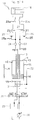
- the telescoping unit 10 consists essentially of at least one telescopic hydraulic cylinder 11 and at least one axially movable in the cylinder tube 12 of the telescopic hydraulic cylinder 11 and connected to a piston rod 13 piston 14.
- the bottom side 15 of the telescopic hydraulic cylinder 11 is at one of a machine or a part the machine (not shown) associated bearing (not shown) attached.
- At least one hydraulic system 18 is assigned to the free end of the telescoping unit 10.
- the hydraulic system 18 is formed in this embodiment as SVE.
- the hydraulic system 18 may be configured to install / remove implements.
- the bolting and Entbolzen of equipment for example, for turning, closing and opening of devices such as pliers, grippers, loading troughs and lifts, are conceivable.
- a hydraulic medium acted upon by hydraulic energy and forwarded to the hydraulic system 18.
- the hydraulic system 18 is, as in Fig. 1 shown connected to the piston rod side 16 of the telescopic hydraulic cylinder 11 via a line 19.
- the line 19 has a fork 20, which divides the line 19 into a feed line 21 and a return line 22. So that the hydraulic medium can flow in each case only in a predetermined direction in the feed line 21 and the return line 22, correspondingly designed valves 23 and 24 are provided.
- the valves 23 and 24 are formed in this embodiment as check valves.
- the check valve 23 prevents the unwanted reflux of the hydraulic medium from the supply line 21 back to the piston rod side 16 of the telescopic hydraulic cylinder 11.
- the supply line 21 is associated with a bypass 25 which is connected to a first latch 26.
- the buffer 26 is designed as a bladder accumulator in this embodiment.
- the supply line 21 is connected to a control unit 27.
- the control unit 27 is in turn connected to the hydraulic system 18 via the supply line 21a.
- the Control unit 27 detects and regulates the need for hydraulic energy and provides it to the hydraulic system 18, if necessary, from the buffer 26 is available.
- the "relaxed" hydraulic medium from the hydraulic system 18 is now directed into a return line 22a.
- the return flow of the hydraulic medium is regulated by the control unit 27 connected to the return line 22a.
- the expanded hydraulic medium is passed via a bypass 25a into a second intermediate store 28 with a hydraulic medium having a lower pressure than the first intermediate store 26 and stored therebetween.
- a backflow of the hydraulic medium by the control unit 27 and then further into the hydraulic system 18 is avoided by the control unit 27.
- the check valve 24 is connected to the supply line 19, from where the hydraulic medium is pushed back into the cylinder chamber 12 at the appropriate opportunity.
- the hydraulic system 18, the control unit 27, and the latches 26, 28 together with the supply and return lines 19, 21, 21 a and 22, 22 a and the check valves 23 and 24 are formed movable together with the telescopic hydraulic cylinder 11.
- the hydraulic system 18 can be stored floating.
- the hydraulic medium is stored in a reservoir 29, from where it is provided by means of a hydraulic pump 30 via adjusting and control means 31 to the telescopic hydraulic cylinder 11.
- the Fig. 1 shows the telescoping unit 10 according to the invention in an embodiment in which the supply of the hydraulic system 18 with a hydraulic medium through the piston rod 13 with the bottom side of the telescopic hydraulic cylinder 11, with a hydraulic two-way one-space circuit.
- the hydraulic medium can be passed from the piston rod side 16 via a return line 32 to the adjusting and control means 31, from where it is pumped back into the reservoir 29.
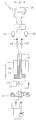
- the Fig. 2 also shows an embodiment of the telescoping unit 10 according to the invention.
- the hydraulic system 18 is supplied with a hydraulic medium, as in Fig. 1 represented, also by the piston rod 13 to the bottom and rod side 15 and 16 of the telescopic hydraulic cylinder 11.
- the embodiment is designed as a two-way hydraulic two-space circuit.
- the check valves 23, 24 and 37, 38 are replaced by electric seat valves. These electric seat valves are then controlled by an electrical control, taking into account the pressure transducer signals of the pressure transducer 42, 42 a.
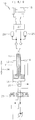
- the Fig . 3 also shows an embodiment of the telecopying unit 10 according to the invention.
- the supply of the hydraulic system 18 with a hydraulic medium takes place, as in the Fig. 2 represented, also by the piston rod 13 to the bottom and rod side 15, 16 of the telescopic hydraulic cylinder 11.
- This embodiment is designed as a hydraulic four-way two-space circuit.
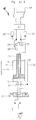
- the Fig. 4 also shows an embodiment of the telescoping unit 10 according to the invention.
- the hydraulic system 18 is supplied with a hydraulic medium, as in FIG Fig. 2 also represented by the piston rod 13 to the bottom and rod side 15, 16 of the telescopic hydraulic cylinder 11.
- the embodiment is, as in Fig. 2 , designed as a hydraulic two-way two-space circuit. But unlike Fig. 2 Here are the charge-discharge lines connected to the piston rod 13 rotated. Thus, the hydraulic medium is pressed from the piston rod side 16 in the memory 26 and from the memory 28, the return takes place in the bottom side 15th
- the Fig. 5 shows the telescoping unit 10 according to the invention in a further embodiment, in which the supply of the hydraulic system 18 with a hydraulic medium, by the piston rod 13 to the piston rod side 16 of the telescopic hydraulic cylinder 11, with a "two-way single-space circuit".
- the Fig. 6 shows the telescoping unit 10 according to the invention in a further embodiment in the supply of the hydraulic system 18 with a hydraulic medium, analog Fig. 3 , So by the piston rod 13, takes place.
- the medium from the reservoir 26 can only flow back into the bottom side 15 via the valve 24.
- Valve 38 is not installed. This is also a "three-way two-space circuit.
- the Fig. 7 shows the telescoping unit 10 according to the invention in a further embodiment in the supply of the hydraulic system 18 with a hydraulic medium, analog Fig. 3 , he follows.
- the medium from the reservoir 26 can only flow back into the rod side 16 via the valve 38.
- valve 24 is not installed. It is also a "three-way two-space circuit".
- the Fig. 8 shows the telescoping unit 10 according to the invention in a further embodiment in the supply of the hydraulic system 18 with a hydraulic medium, analog Fig. 3 , he follows.
- the reservoir 26 is pressurized only via the valve 23 from the bottom side 15.
- valve 37 is not installed. It is also a "three-way two-space circuit".
- the Fig. 9 shows the telescoping unit 10 according to the invention in a further embodiment in the supply of the hydraulic system 18 with a hydraulic medium, analog Fig. 3 , he follows.
- the pressure supply of the memory 26 takes place only via the valve 37 and only from the rod side 16. There is no charging connection to the bottom side 15. Again, there is a "three-way two-space circuit".
Description
Die vorliegende Erfindung betrifft eine Teleskopiereinheit zum Teleskopieren von an Maschinen angeordneten Mitteln, umfassend mindestens einen Teleskophydraulikzylinder und mindestens eine weitere Hydraulikanlage (18), wobei der Teleskophydraulikzylinder (11) mindestens einen in dem Zylinderraum des Teleskophydraulikzylinder axial verfahrbar angeordneten und mit einer Kolbenstange verbundenen Kolben, wobei die Bodenseite des Teleskophydraulikzylinders an einem der Maschine zugeordneten Lager festlegbar ausgebildet ist und am exponierten Ende der Kolbenstange die mindestens eine weitere Hydraulikanlage angeordnet ist, die über ein hydraulisches Medium mit hydraulischer Energie beaufschlagt wird wobei durch das Stellen des Kolbens in dem Teleskophydraulikzylinder die hydraulische Energie, die sich durch die Änderung des Betriebszustandes und dem sich daraus ergebenen hydraulischen Druckunterschied des hydraulischen Mediums, in mindestens einem ersten Zwischenspeicher abgeleitet und gespeichert wird, um damit die Hydraulikanlage mit der hydraulischen Energie aus dem ersten Zwischenspeicher in einem Bedarfsfall zu beaufschlagen und wobei nach Verbrauch, der im hydraulischen Medium gespeicherten hydraulischen Energie, das hydraulische Medium von der Hydraulikanlage in mindestens einen zweiten Zwischenspeicher geleitet wird, und von dort wieder in den Teleskophydraulikzylinder geleitet wird, wo es erneut mit hydraulischer Energie beaufschlagt oder einem Hydraulikprimärkreislauf der Teleskopiereinheit zugeführt wird.The present invention relates to a telescoping unit for telescoping means arranged on machines, comprising at least one telescopic hydraulic cylinder and at least one further hydraulic system (18), wherein the telescopic hydraulic cylinder (11) at least one in the cylinder chamber of the telescopic hydraulic cylinder arranged axially movable and connected to a piston rod piston, wherein the bottom side of the Teleskophydraulikzylinders is fixed to a bearing associated with the machine and at the exposed end of the piston rod, the at least one further hydraulic system is arranged, which is acted upon by a hydraulic medium with hydraulic energy wherein by placing the piston in the telescopic hydraulic cylinder, the hydraulic energy , Derived by the change in the operating condition and the resulting hydraulic pressure difference of the hydraulic medium in at least a first buffer and ges is accumulated, so as to pressurize the hydraulic system with the hydraulic energy from the first buffer in a case of need and wherein after consumption, the hydraulic medium stored in the hydraulic medium, the hydraulic medium is passed from the hydraulic system in at least a second buffer, and from there is returned to the telescopic hydraulic cylinder, where it is again subjected to hydraulic energy or supplied to a hydraulic primary circuit of the telescoping unit.
Wenn Teile von Maschinen teleskopartig mit einander verbunden sind und diese Teile mit Hilfe eines Teleskophydraulikzylinders teleskopiert werden, so ist es erforderlich, um eine weitere Funktion am exponierten Ende des Teleskophydraulikzylinders zu ermöglichen, eine Schlauchführung (Flansch, Trommel usw.), ein separates Hydraulikaggregat oder ein Hydraulikzylinder mit einer inneren Öldurchführung zu installieren.When parts of machines are telescopically connected and these parts are telescoped by means of a telescopic hydraulic cylinder, it is necessary to allow another function at the exposed end of the telescopic hydraulic cylinder, a hose guide (flange, drum, etc.), a separate hydraulic unit or to install a hydraulic cylinder with an internal oil passage.
Damit beispielsweise ein Mobilkran mit teleskopierbaren Ausleger, bei kleinem Gegengewicht große Lasten heben kann, muss der Ausleger möglichst klein sein. Vor allem bei größeren Arbeitsradien ist es notwendig das Gewicht, der über die Stützbasis hinausragenden Auslegerteile, so klein wie möglich zu halten. Auch beim Transport eines Mobilkranes ist es günstiger, wenn ein möglichst geringes Eigengewicht bewegt werden muss.For example, a mobile crane with telescopic boom, with small counterweight can lift large loads, the boom must be as small as possible. Especially with larger working radii, it is necessary to keep the weight of the outrigger parts projecting beyond the support base as small as possible. Even when transporting a mobile crane, it is cheaper if the lowest possible weight has to be moved.
Aufgrund dessen werden in der Mehrheit Einzylindertelekopiereinheiten mit einer Sicherungs- und Verbolzungseinheit - im Folgenden als SVE bezeichnet - in derartige Mobilkrane verbaut. Bei diesem System wird ein Teleskopkasten mit Hilfe der SVE am Teleskophydraulikzylinder gesichert und danach vom umgebenen Teleskopkasten entbolzt. Nun fährt der Teleskophydraulikzylinder mit dem Teleskopkasten auf die gewünschte Länge aus und verbolzt die Teleskopkästen miteinander und entsichert den Teleskophydraulikzylinder vom soeben bewegten Teleskopkasten. Dieser Vorgang wird so oft wiederholt, bis alle Teleskopkästen eines Teleskopauslegers ihre Arbeitsposition erreicht haben. Zur Verringerung des auslegerseitigen Drehmoments wird der Teleskophydraulikzylinder wieder vollständig in eine Ausgangsposition eingefahren. Erst jetzt kann der ausgefahrene Ausleger maximal belastet werden.Due to this, in the majority of single-cylinder telecopying units with a securing and bolting unit - hereinafter referred to as SVE - installed in such mobile cranes. In this system, a telescopic box is secured to the telescopic hydraulic cylinder using the SVE and then unbolted from the surrounding telescopic box. Now, the telescopic hydraulic cylinder with the telescopic box extends to the desired length and bolted the telescopic boxes together and unlocks the telescopic hydraulic cylinder from just moved telescope box. This process is repeated until all telescopic boxes of a telescopic boom have reached their working position. To reduce the boom side torque of the telescopic hydraulic cylinder is fully retracted to a starting position. Only now can the extended boom be loaded to the maximum.
Bei diesen Systemen befindet sich die SVE am exponierten Ende des Teleskophydraulikzylinders. Die hydraulische Energie wird folglich auch an dieser Stelle benötigt, damit die Kästen ent- bzw. verriegelt werden können. Nachteilig dabei ist, dass genau diese Stelle mit dem Teleskophydraulikzylinder hin und her gefahren wird. Damit ist die SVE nicht direkt für Hydraulikleitungen erreichbar.In these systems, the SVE is located at the exposed end of the telescopic hydraulic cylinder. The hydraulic energy is therefore also needed at this point, so that the boxes can be unlocked or locked. The disadvantage here is that exactly this point is driven back and forth with the telescopic hydraulic cylinder. Thus, the SVE is not directly accessible for hydraulic lines.
Aus dem Stand der Technik sind zumindest zwei Ansätze bekannt, um die Ölversorgung und damit die Versorgung mit hydraulischer Energie zu gewährleisten: - Eine parallel zum Teleskophydraulikzylinder, mittels Energiekette, geführte Hydraulikschläuche.From the prior art, at least two approaches are known to ensure the supply of oil and thus the supply of hydraulic energy: - A parallel to the telescopic hydraulic cylinder, by means of energy chain, guided hydraulic hoses.
Nachteil hierbei ist, dass die Führung dieser Hydraulikschläuche sehr viel Platz benötigt, der insbesondere bei kleineren Teleskopkästen nicht vorhanden ist. - Eine teleskopierbare Hydraulikleitung, die direkt durch den Teleskophydraulikzylinder geführt wird, um das Hydrauliköl an die SVE leiten zu können.The disadvantage here is that the leadership of these hydraulic hoses requires a lot of space, which is not available especially for smaller telescopic boxes. - A telescopic hydraulic line that passes directly through the telescopic hydraulic cylinder to direct hydraulic oil to the SVE.
Diese Art der Ölführung spart zwar Platz, ist aber mit dem Nachteil verbunden, dass eine derartige Anordnung teuer und störanfällig ist (Druckübersetzung im Durchführungsrohr führen zu Problemen). Im Falle einer Havarie kann diese nur mit einem erheblichen, zeitlichen und damit verbundenen finanziellen Aufwand behoben werden. Zur Reparatur muss der gesamte Teleskophydraulikzylinder ausgebaut und zerlegt werden.Although this type of oil guide saves space, but has the disadvantage that such an arrangement is expensive and prone to failure (pressure transmission in the bushing lead to problems). In the event of an accident, this can be remedied only with a considerable, temporal and associated financial expense. For repair, the entire telescopic hydraulic cylinder must be removed and disassembled.
Die Offenlegungsschrift
Es ist daher eine Aufgabe der vorliegenden Erfindung, eine Teleskopiereinheit der eingangs beschriebenen Art zu schaffen, mit der die oben genannten Nachteile überwunden werden können.It is therefore an object of the present invention to provide a telescoping unit of the type described above, with which the above-mentioned disadvantages can be overcome.
Diese Aufgabe wird durch die im Anspruch 1 angegebenen Merkmale gelöst, insbesondere dadurch, dass die Versorgung der Hydraulikanlage mit dem hydraulischen Medium durch die Kolbenstange des Teleskophydraulikzylinders erfolgt.This object is achieved by the features specified in claim 1, in particular in that the supply of the hydraulic system with the hydraulic medium takes place through the piston rod of the telescopic hydraulic cylinder.
Gemäß einer vorteilhaften Ausführungsform sind die Hydraulikanlage, die Steuereinheit, sowie die ersten und zweiten Zwischenspeicher nebst Zu- und Rücklaufleitungen und Rückschlagventilen zusammen mit dem Teleskophydraulikzylinder verfahrbar ausgebildet.According to an advantageous embodiment, the hydraulic system, the control unit, as well as the first and second latches along with supply and return lines and check valves are designed to be movable together with the telescopic hydraulic cylinder.
Ferner ist es vorgesehen, dass die Steuereinheit, sowie die ersten und zweiten Zwischenspeicher nebst Zu- und Rücklaufleitungen und Rückschlagventilen an dem exponierten Ende des Teleskophydraulikzylinders und somit am exponierten Ende der Kolbenstange angeordnet sind.Further, it is provided that the control unit, and the first and second latches are arranged together with supply and return lines and check valves at the exposed end of the telescopic hydraulic cylinder and thus at the exposed end of the piston rod.
Gemäß einer weiteren vorteilhaften Ausführungsform der erfindungsgemäßen Teleskopiereinheit, werden Drücke in den ersten und zweiten Zwischenspeichern mit Druckaufnehmern gemessen und die gemessenen Druckdaten werden von einem Rechner verarbeitet oder direkt zu einer Steuereinheit gesendet, die Steuereinheit bewirkt, dass der erste Zwischenspeicher automatisch mit dem hydraulischen Medium geladen wird, sobald der Druck des hydraulischen Mediums im Teleskophydraulikzylinder höher ist als der Druck des hydraulischen Mediums im ersten Zwischenspeicher und, dass. der zweite Zwischenspeicher automatisch von dem hydraulischen Medium entladen, sobald der Druck des hydraulischen Mediums im Teleskophydraulikzylinder kleiner ist als der Druck des hydraulischen Mediums im zweiten ZwischenspeicherAccording to a further advantageous embodiment of the telescoping unit according to the invention, pressures in the first and second latches are measured with pressure transducers and the measured pressure data are processed by a computer or sent directly to a control unit, the control unit causes the first latches to be automatically charged with the hydraulic medium becomes as soon as the pressure of the hydraulic medium in the telescopic hydraulic cylinder is higher than the pressure of the hydraulic medium in the first intermediate storage and, that the second buffer automatically discharged from the hydraulic medium when the pressure of the hydraulic medium in the telescopic hydraulic cylinder is smaller than the pressure of the hydraulic medium in the second buffer
Beispielsweise bei Lastwechsel treten hohe und tiefe Drücke im hydraulischen System auf. Die Zwischenspeicher fungieren dabei als Vorratsbehälter, die die hohen und tiefen Drücke in dem hydraulischen System zwischenspeichern. Der Vorgang des Ladens und des Entladens der Zwischenspeicher kann dabei, je nach Ausführung, sogar zeitgleich erfolgen.For example, during load changes occur high and low pressures in the hydraulic system. The buffers act as storage tanks, which buffer the high and low pressures in the hydraulic system. The process of loading and unloading the buffer can, depending on the version, even occur at the same time.
Bei der erfindungsgemäßen Teleskopiereinheit ist es vorgesehen, mindestens zwei Zwischenspeicher, jeweils einen für den hohen Druck und einen für den tiefen Druck, die in Wirkverbindung mit der Hydraulikanlage (beispielsweise eine SVE) stehen, mit der Teleskopiereinheit hydraulisch zu verbinden. Die Anzahl der Zwischenspeicher soll hierauf aber nicht beschränkt sein.In the telescoping unit according to the invention, it is provided to connect at least two buffer stores, one each for the high pressure and one for the low pressure, which are in operative connection with the hydraulic system (for example an SVE) with the telescoping unit hydraulically. The number of buffers should not be limited to this.
Die Versorgung der Hydraulikanlage mit hydraulischer Energie wird durch die Zwischenspeicher gewährleistet. Die Zwischenspeicher können hierbei als Blasenspeicher oder Kolbenspeicher oder Federspeicher ausgebildet sein. Dabei können die Speicher für den hohen Druck und für den davon zu unterscheidenden niedrigen Druck über Rückschlagventile direkt mit dem Teleskophydraulikzylinder verbunden sein.The supply of hydraulic power to the hydraulic system is ensured by the intermediate storage. The latches may be formed here as a bladder accumulator or piston accumulator or spring accumulator. The memory for the high pressure and for the different low pressure to be connected via check valves directly to the telescopic hydraulic cylinder.
In einer besonders bevorzugten Ausführungsform der erfindungsgemäßen Teleskopiereinheit, wird der erste Zwischenspeicher für den hohen Druck dabei automatisch befüllt, bzw. über das hydraulische Medium mit Druck beaufschlagt, sprich mit hydraulischer Energie aufgeladen, wenn der hydraulische Druck im Bodenraum des Teleskophydraulikzylinders höher ist als der Druck im ersten Zwischenspeicher selbst. Dies kann beispielsweise beim Austeleskopieren, bei statischer Last oder beim Ausfahren des Teleskophydraulikzylinders im verbolzten und gesicherten Zustand bis auf Anschlag der Fall sein.In a particularly preferred embodiment of the telescoping unit according to the invention, the first buffer for the high pressure is automatically filled, or pressurized via the hydraulic medium, that is charged with hydraulic energy when the hydraulic pressure in the bottom space of the telescopic hydraulic cylinder is higher than the pressure in the first intermediate store itself. This can be the case, for example, during telescoping, under static load or during extension of the telescopic hydraulic cylinder in the bolted and secured state until it stops.
In einer weiteren vorteilhaften Ausführungsform der erfindungsgemäßen Teleskopiereinheit wird der zweite Zwischenspeicher automatisch von dem hydraulischen Medium entladen, sobald der Druck des hydraulischen Mediums im Teleskophydraulikzylinder kleiner ist als der Druck des hydraulischen Mediums im zweiten Zwischenspeicher. Dies kann beispielsweise der Fall sein, wenn das bodenseitige Ventil des Teleskophydraulikzylinders geöffnet wird (d.h. die Reibung ist dann größer als die statische Last) oder der Teleskophydraulikzylinder im verbolzten und gesicherten Zustand bis auf Anschlag eingefahren wird.In a further advantageous embodiment of the telescoping unit according to the invention, the second buffer is automatically discharged from the hydraulic medium as soon as the pressure of the hydraulic medium in the telescopic hydraulic cylinder is smaller than the pressure of the hydraulic medium in the second Buffer. This may for example be the case when the bottom-side valve of the telescopic hydraulic cylinder is opened (ie, the friction is greater than the static load) or the telescopic hydraulic cylinder is retracted in the bolted and secured state to the stop.
Damit die Funktionstüchtigkeit der Hydraulikanlage - beispielsweise die einer SVEsichergestellt werden kann, können die Drücke in den Zwischenspeichern mit Druckaufnehmern gemessen und in einer Steuerung verarbeitet werden.So that the functionality of the hydraulic system - for example, the SVEs can be ensured, the pressures in the buffers can be measured with pressure transducers and processed in a controller.
In einer weiteren bevorzugten Ausführungsform der erfindungsgemäßen Teleskopiereinheit steuert die Steuereinheit und /oder der Rechner in Abhängigkeit von den an sie von den Druckaufnehmern ermittelten und übersandten Druckdaten, die Teleskopiereinheit an, um durch die Änderung des Fahrzustandes die Zwischenspeicher mit hydraulischer Energie zu laden bzw. zu entladen.In a further preferred embodiment of the telescoping unit according to the invention, the control unit and / or the computer controls the telescoping unit as a function of the pressure data determined and sent to it by the pressure transducers in order to load or load the buffer memories with hydraulic energy by changing the driving condition discharged.
Hierbei soll auch die Möglichkeit bestehen, dass die Steuerung die Hydraulikanlage über die Druckaufnehmer ansteuert, um die Hydraulikanlage mit hydraulischer Energie zu beaufschlagen, sobald die Steuerung im ersten Zwischenspeicher eine für das Stellen der Hydraulikanlage unzureichende Menge an hydraulischer Energie ermittelt. Die Druckaufnehmer sind dabei so ausgebildet, dass sie den Druck des hydraulischen Mediums in ein proportionales elektrisches Signal umwandeln können.This should also be possible that the controller controls the hydraulic system via the pressure transducer to pressurize the hydraulic system with hydraulic energy as soon as the controller determines in the first latch for the placement of the hydraulic system insufficient amount of hydraulic energy. The pressure transducers are designed so that they can convert the pressure of the hydraulic medium into a proportional electrical signal.
Zum besseren Verständnis wird im Nachfolgenden eine "X-Wege-Y-Raum-Schaltung definiert als:
- X -Wege ist die Anzahl der Verbindungen über die Rückschlagventile in die Zylinderräume des Telekophydraulikzylinders.
- Y-Raum ist die Anzahl der Zylinderinnenräume des Teleskophydraulikzylinders, wobei Ein-Raum die Boden- oder die Stangenseite darstellt. Zwei-Raum stellt die Boden- und die Stangenseite dar. Die normalen Zylinderanschlüsse zum Fahren des Zylinders werden hierbei nicht mitgezählt.
- X-paths is the number of connections via the check valves in the cylinder chambers of the Telekophydraulikzylinders.
- Y-space is the number of cylinder interiors of the telescopic hydraulic cylinder, with one-space representing the bottom or the rod side. Two-chamber represents the bottom and the rod side. The normal cylinder connections for driving the cylinder are not counted here.
In einer anderen Ausführungsform erfolgt die Versorgung der Hydraulikanlage mit dem hydraulischen Medium über die Bodenseite durch die Kolbenstange des Teleskophydraulikzylinders in einer hydraulischen Zwei-Wege-Ein-Raum-Schaltung.In another embodiment, the supply of the hydraulic system with the hydraulic medium via the bottom side by the piston rod of the telescopic hydraulic cylinder in a hydraulic two-way single-space circuit.
Besonders vorteilhaft ist es, mit Hilfe der von dem Druckaufnehmer erfassten Druckaufnehmersignale diese im Rechner oder in der Steuereinheit selbst zu verarbeiten, um so die ermittelten Werte zum Stellen von elektrischen Ventilen (Sitzventilen) zu verwenden, über die das Laden und Entladen der Zwischenspeicher geregelt bzw. gesteuert werden kann. Hierdurch könnten konventionelle Rückschlagventile ersetzt werden. Dadurch lässt sich nicht nur das Laden und Entladen der Zwischenspeicher steuern, sondern es ist somit auch möglich den Maximaldruck in den Speichern zu begrenzen. Des Weiteren kann beim Laden der Zwischenspeicher ein bestimmter Druckunterschied (Delta-P) eingehalten werden. Damit ist die entnehmbare Leistung für die Hydraulikanlage festlegbar und es bedarf keiner eventuellen weiteren Druckanpassung. Statt der elektrischen Ventile können in einer weiteren Ausführungsform auch hydraulisch angesteuerte Ventile verwendet werden.It is particularly advantageous to process these with the aid of the pressure sensor signals detected by the pressure transducer in the computer or in the control unit itself so as to use the values determined for setting electric valves (poppet valves) via which the loading and unloading of the intermediate memory is regulated or controlled can be controlled. This could replace conventional check valves. As a result, not only the loading and unloading of the buffer can be controlled, but it is also possible to limit the maximum pressure in the memories. Furthermore, when loading the buffer a certain pressure difference (Delta-P) can be maintained. Thus, the removable power for the hydraulic system is fixed and there is no need for any further pressure adjustment. Instead of the electric valves and hydraulically controlled valves can be used in a further embodiment.
Vorteilhaft ist es auch, wenn die Ölversorgung für die Hydraulikanlage die über die Kolbenstangen- und Bodenseite des Teleskophydraulikzylinders in einer hydraulischen Drei-Wege-Zwei-Raum-Schaltung erfolgt, wobei die Hydraulikanlage an der Kolbenstange des Teleskophydraulikzylinders angeschlossen ist und das Rücköl nur in die Bodenseite geleitet werden kann. Auch könnte das Rücköl nur in die Kolbenstangenseite geleitet werden.It is also advantageous if the oil supply for the hydraulic system via the piston rod and bottom side of the Teleskophydraulikzylinders in a hydraulic three-way two-space circuit, the hydraulic system is connected to the piston rod of the telescopic hydraulic cylinder and the return oil only in the Bottom side can be passed. Also, the return oil could only be directed into the piston rod side.
Des Weiteren kann die Ölversorgung für die Hydraulikanlage die über die Kolbenstangen- und Bodenseite des Teleskophydraulikzylinders auch in einer hydraulischen Drei-Wege-Zwei-Raum-Schaltung erfolgen, wobei die Hydraulikanlage an der Kolbenstange des Teleskophydraulikzylinders angeschlossen ist und das Drucköl nur aus der Stangenseite entnommen wird.Furthermore, the oil supply for the hydraulic system can be done via the piston rod and bottom side of the telescopic hydraulic cylinder in a hydraulic three-way two-space circuit, the hydraulic system is connected to the piston rod of the Teleskophydraulikzylinders and removed the pressure oil only from the rod side becomes.
Die Erfindung wird im Folgenden anhand von beispielhaften Ausführungsformen unter Bezugnahme auf die beigefügten Zeichnungen näher erläutert. Die Figuren zeigen:
-
Fig. 1 die schematische Schaltskizze der erfindungsgemäßen Teleskopiereinheit in einer teilweise geschnittenen Ansicht, mit einer Ölversorgung für die Hydraulikanlage, die über die Stangenseite des Teleskophydraulikzylinders in einer hydraulischen Zwei-Wege-Ein-Raum-Schaltung erfolgt; -
Fig. 2 die schematische Schaltskizze der erfindungsgemäßen Teleskopiereinheit in einer teilweise geschnittenen Ansicht, mit einer Ölversorgung für die Hydraulikanlage, die über die Stangenseite des Teleskophydraulikzylinders in einer hydraulischen Zwei-Wege-Zwei-Raum-Schaltung erfolgt; -
Fig. 3 die schematische Schaltskizze der erfindungsgemäßen Telekopiereinheit, wobei die Hydraulikanlage an der Stangenseite des Teleskopierzylinders angeschlossen ist; -
Fig. 4 die schematische Schaltskizze der erfindungsgemäßen Telekopiereinheit gemäßFig. 2 , mit gedrehten Lade- bzw. Entladeanschlüssen an der Kolbenstangenseite; -
Fig. 5 die schematische Schaltskitzze der erfindungsgemäßen Teleskopiereinheit gemäßFig. 1 , wobei der Anschluss hier auch durch die Kolbenstange, aber nicht zur Bodenseite des Teleskopzylinders, sondern zu dessen Stangenseite erfolgt; -
Fig. 6 die schematische Schaltskizze der erfindungsgemäßen Teleskopiereinheit in einer teilweise geschnittenen Ansicht, mit einer Ölversorgung für die Hydraulikanlage, die über die Kolbenstangen- und Bodenseite des Teleskophydraulikzylinders in einer hydraulischen "drei Wege, zwei Raum" Schaltung erfolgt; die Hydraulikanlage ist an der Kolbenstange des Teleskopierzylinders angeschlossen, wobei im Unterschied zuFig. 3 das Rücköl nur in die Bodenseite geleitet wird; -
Fig. 7 die schematische Schaltskitzze der erfindungsgemäßen Teleskopiereinheit gemäßFig. 3 , wobei hier das Rücköl nur in die Stangenseite geleitet wird; -
Fig. 8 die schematische Schaltskizze der erfindungsgemäßen Teleskopiereinheit in einer teilweise geschnittenen Ansicht, mit einer Ölversorgung für die Hydraulikanlage, die über die Kolbenstangen- und Bodenseite des Teleskophydraulikzylinders in einer hydraulischen "drei Wege, zwei Raum" Schaltung erfolgt; die Hydraulikanlage ist an der Kolbenstange des Teleskopierzylinders angeschlossen, wobei im Unterschied zuFig. 3 das Drucköl nur aus der Bodenseite entnommen wird; -
Fig. 9 die schematische Schaltskitzze der erfindungsgemäßen Teleskopiereinheit gemäßFig. 3 , wobei hier das Drucköl nur aus der Bodenenseite entnommen wird.
-
Fig. 1 the schematic circuit diagram of the telescoping unit according to the invention in a partially sectioned view, with an oil supply for the hydraulic system, which takes place via the rod side of the Teleskophydraulikzylinders in a hydraulic two-way single-room circuit; -
Fig. 2 the schematic circuit diagram of the telescoping unit according to the invention in a partially sectioned view, with an oil supply for the hydraulic system over the rod side of the telescopic hydraulic cylinder takes place in a hydraulic two-way two-space circuit; -
Fig. 3 the schematic circuit diagram of the invention Telekopiereinheit, wherein the hydraulic system is connected to the rod side of Teleskopierzylinders; -
Fig. 4 the schematic circuit diagram of the Telekopiereinheit according to the inventionFig. 2 with rotated charge and discharge ports on the piston rod side; -
Fig. 5 the schematic Schaltskitzze the telescoping unit according to the invention according toFig. 1 , wherein the connection also takes place here by the piston rod, but not to the bottom side of the telescopic cylinder, but to the rod side; -
Fig. 6 the schematic circuit diagram of the telescoping unit according to the invention in a partially sectioned view, with an oil supply for the hydraulic system, which takes place via the piston rod and bottom side of the Teleskophydraulikzylinders in a hydraulic "three way, two room"circuit; the hydraulic system is connected to the piston rod of the telescoping cylinder, unlikeFig. 3 the return oil is only directed to the bottom side; -
Fig. 7 the schematic Schaltskitzze the telescoping unit according to the invention according toFig. 3 , whereby here the return oil is led only in the rod side; -
Fig. 8 the schematic circuit diagram of the telescoping unit according to the invention in a partially sectioned view, with an oil supply for the hydraulic system, which takes place via the piston rod and bottom side of the Teleskophydraulikzylinders in a hydraulic "three way, two room"circuit; the hydraulic system is connected to the piston rod of the telescoping cylinder, unlikeFig. 3 the pressure oil is taken only from the bottom side; -
Fig. 9 the schematic Schaltskitzze the telescoping unit according to the invention according toFig. 3 , where here the pressure oil is taken only from the bottom side.
Wie in der
Die Hydraulikanlage 18 ist in dieser Ausführungsform als SVE ausgebildet. In anderen Ausführungsformen kann die Hydraulikanlage 18 beispielsweise dazu ausgebildet sein, um Arbeitsgeräte an-/abzubauen. Das Verbolzen und Entbolzen von Arbeitsgeräten beispielsweise zum Drehen, Schließen und Öffnen von Vorrichtungen wie beispielsweise Zangen, Greifern, Lademulden und Hebebühnen, sind denkbar. Hierzu wird ein hydraulisches Medium, mit hydraulischer Energie beaufschlagt und an die Hydraulikanlage 18 weitergeleitet.The
Die Hydraulikanlage 18 ist, wie in
Im Folgenden wird der Weg des hydraulischen Mediums in der Zulaufleitung 21 nach dem Rückschlagventil 23 in Richtung der Hydraulikanlage 18 zuerst beschrieben. Das Rückschlagventil 23 verhindert den ungewollten Rückfluss des hydraulischen Mediums aus der Zuleitung 21 zurück zur Kolbenstangenseite 16 des Teleskophydraulikzylinders 11. Der Zuleitung 21 ist ein Bypass 25 zugeordnet, der mit einem ersten Zwischenspeicher 26 verbunden ist. Der Zwischenspeicher 26 ist in dieser Ausführungsform als Blasenspeicher ausgebildet.In the following, the path of the hydraulic medium in the
Durch die sich ändernden Betriebszustände ergeben sich Druckunterschiede im Teleskophydraulikzylinder 11 und damit auch in der Zulaufleitung 21. Diese Druckunterschiede entstehen beispielsweise, wenn Lasten gefahren oder wenn gegen Verbolzungslöcher oder Endanschläge und dgl. gefahren wird. Auch bei gleichbleibender Belastung ergeben sich durch die unterschiedlichen Boden- zu Ringflächenverhältnisse unterschiedliche Hydraulikdrücke in dem Teleskophydraulikzylinder 11. Diese Druckunterschiede stellen ein Energiepotential dar, das für zusätzliche Arbeiten genutzt werden kann. Die höheren Drücke in der hydraulischen Flüssigkeit werden nun über den Bypass 25 in den Zwischenspeicher 26 geleitet und bis auf Weiteres bevorratet.Due to the changing operating conditions, there are differences in pressure in the telescopic
Die Zulaufleitung 21 ist mit einer Steuereinheit 27 verbunden. Die Steuereinheit 27 ist wiederum über die Zulaufleitung 21a an die Hydraulikanlage 18 angeschlossen. Die Steuereinheit 27 erfasst und regelt den Bedarf an hydraulischer Energie und stellt diese der Hydraulikanlage 18 im Bedarfsfall aus dem Zwischenspeicher 26 zur Verfügung.The
Nach verrichteter Arbeit wird nun das "entspannte" hydraulische Medium aus der Hydraulikanlage 18 in eine Rücklaufleitung 22a geleitet. Der Rückfluss des hydraulischen Mediums wird von der mit der Rücklaufleitung 22a verbundenen Steuereinheit 27 geregelt. Das entspannte hydraulische Medium wird über einen Bypass 25a in einen zweiten Zwischenspeicher 28 mit gegenüber dem ersten Zwischenspeicher 26 niedrigeren Druck aufweisenden hydraulischen Medium geleitet und zwischengelagert. Ein Zurückfließen des hydraulischen Mediums durch die Steuereinheit 27 und dann weiter in die Hydraulikanlage 18 wird durch die Steuereinheit 27 vermieden. Das Rückschlagventil 24 ist mit der Zuleitung 19 verbunden, von wo aus das hydraulische Medium bei passender Gelegenheit wieder in den Zylinderraum 12 zurück gedrückt wird.After completed work, the "relaxed" hydraulic medium from the
Die Hydraulikanlage 18, die Steuereinheit 27, sowie die Zwischenspeicher 26, 28 nebst den Zu- und Rücklaufleitungen 19, 21, 21 a und 22, 22a und den Rückschlagventilen 23 und 24 sind zusammen mit dem Teleskophydraulikzylinder 11 verfahrbar ausgebildet. Die Hydraulikanlage 18 kann dabei schwimmend gelagert sein.The
Das hydraulische Medium wird in einem Vorratsbehälter 29 bevorratet, von wo aus es mittels einer hydraulischen Pumpe 30 über Stell- und Regelmittel 31 dem Teleskophydraulikzylinder 11 zur Verfügung gestellt wird.The hydraulic medium is stored in a
Die
Die
In einer weiteren, nicht dargestellten, Ausführungsform werden die Rückschlagventile 23, 24 und 37, 38 durch elektrische Sitzventile ersetzt. Diese elektrischen Sitzventile werden dann auch von einer elektrischen Steuerung unter Berücksichtigung der Druckaufnehmersignale der Druckaufnehmer 42, 42a angesteuert.In another embodiment, not shown, the
Die
Die
Die
Die
Die
Die
Die
- 10 Teleskopiereinheit10 telescope unit
- 11 Teleskophydraulikzylinder11 Telescopic hydraulic cylinders
- 12 Zylinderrohr12 cylinder tube
- 13 Kolbenstange13 piston rod
- 14 Kolben14 pistons
- 15 Bodenseite15 bottom side
- 16 Kolbenstangenseite16 piston rod side
- 18 Hydraulikanalge18 hydraulic system
- 19 Leitung19 line
- 20 Gabelung20 bifurcation
- 21, 21a Zulaufleitung21, 21a supply line
- 22, 22a Rücklaufleitung22, 22a return line
- 23 Ventil23 valve
- 24 Ventil24 valve
- 25, 25a Bypass25, 25a bypass
- 26 Zwischenspeicher26 cache
- 27 Steuereinheit27 control unit
- 28 Zwischenspeicher28 cache
- 29 Vorratsbehälter29 storage tank
- 30 Pumpe30 pump
- 31 Stellmittel/Regelmittel31 Adjusting agent / control agent
- 32 Rücklaufleitung32 return line
- 33 Stangenseite33 bar side
- 34 Axialrichtung/Pfeil34 axial direction / arrow
- 35 Leitung35 line
- 36 Leitung36 line
- 37 Ventil37 valve
- 38 Ventil38 valve
- 39 Zwischenspeicher39 cache
- 40 Zwischenspeicher40 buffers
- 41, 41a Bypassleitung41, 41a bypass line
- 42, 42a Druckaufnehmer42, 42a pressure transducer
Claims (19)
- Telescopic unit (10) for telescoping means arranged on machines, comprising at least one telescopic hydraulic cylinder (11) and at least one additional hydraulic system (18), wherein the telescopic hydraulic cylinder (11) comprises at least one piston (14) arranged to be axially movable in the cylinder chamber of the telescopic hydraulic cylinder (11) and connected to a piston rod (13), wherein a bottom side (15) of the telescopic hydraulic cylinder (11) is configured to be fixable to a bearing allocated to the machine, and the at least one additional hydraulic system (18) is arranged on the exposed end of the piston rod (13) and is energised with hydraulic energy via a hydraulic medium, wherein by adjusting the piston (14) in the telescopic hydraulic cylinder (11), the hydraulic energy, which comes from by the change in the operating state and the resulting difference in hydraulic pressure of the hydraulic medium, is diverted to and stored in at least one first intermediate reservoir (26, 39), in order thereby to energise the hydraulic system (18) with the hydraulic energy from the first intermediate reservoir (26, 39) if necessary, and wherein, after consumption of the hydraulic energy stored in the hydraulic medium, the hydraulic medium is fed from the hydraulic system (18) into at least one second intermediate reservoir (28, 40), and from there is fed into the telescopic hydraulic cylinder (11), where it is again energised with hydraulic energy or conveyed to a primary hydraulic circuit of the telescopic unit (10), wherein the hydraulic system (18) is supplied with the hydraulic medium by the piston rod (13) of the telescopic hydraulic cylinder (11).
- Telescopic unit as claimed in claim 1, characterised in that the pressures in the first and second intermediate reservoirs (26, 39, 28, 40) are measured with pressure sensors (42, 42a) and the measured pressure data are processed by a computer or are sent directly to a control unit (27), wherein the hydraulic system (18), the control unit (27) and the first and second intermediate reservoirs (26, 28, 39, 40) in addition to feed and return lines (19, 21, 21a, 22, 22a) and check valves (23, 24) are configured to be movable together with the telescopic hydraulic cylinder (11).
- Telescopic unit as claimed in claim 1 or 2, characterised in that the pressures in the first and second intermediate reservoirs (26, 39, 28, 40) are measured with pressure sensors (42, 42a) and the measured pressure data are processed by a computer or are sent directly to a control unit (27), wherein the control unit (27) and the first and second intermediate reservoirs (26, 28, 39, 40) in addition to feed and return lines (19, 21, 21a, 22, 22a) and check valves (23, 24) are arranged on the exposed end of the telescopic hydraulic cylinder (11) and thus on the exposed end of the piston rod (13).
- Telescopic unit as claimed in any one of claims 1 to 3, characterised in that the pressures in the first and second intermediate reservoirs (26, 39, 28, 40) are measured with pressure sensors (42, 42a) and the measured pressure data are processed by a computer or are sent directly to a control unit (27), the control unit (27) ensures that the first intermediate reservoir (26, 39) is automatically loaded with the hydraulic medium as soon as the pressure of the hydraulic medium in the telescopic hydraulic cylinder (11) is higher than the pressure of the hydraulic medium in the first intermediate reservoir (26, 39), and that the hydraulic medium is automatically unloaded from the second intermediate reservoir (28, 40) as soon as the pressure of the hydraulic medium in the telescopic hydraulic cylinder (11) is lower than the pressure of the hydraulic medium in the second intermediate reservoir (28, 40).
- Telescopic unit as claimed in any one of claims 1 to 4, characterised in that the first and second intermediate reservoirs (26, 39, 28, 40) are configured as bladder reservoirs or as piston reservoirs or as spring reservoirs.
- Telescopic unit as claimed in claim 4 or 5, characterised in that the control unit (27) or the computer, depending on the pressure data determined and transmitted by the pressure sensors (42, 42a) thereto, activates the telescopic unit (10) in order to load the intermediate reservoirs (26, 39, 28, 40) with hydraulic energy or unload hydraulic energy from them by changing the driving state.
- Telescopic unit as claimed in claim 6, characterised in that, with processing of the data from the pressure sensors (42, 42a), the control unit (27) or the computer energies the hydraulic system (18) with hydraulic energy only when the pressure difference between the first intermediate reservoirs (26, 39) and the second intermediate reservoirs (28, 40) has reached a predefined minimum value.
- Telescopic unit as claimed in claim 7, characterised in that the pressure sensors (42, 42a) convert the pressure of the hydraulic medium into a proportional electrical signal.
- Telescopic unit as claimed in claim 7, characterised in that the hydraulic system (18) is supplied with the hydraulic medium from the bottom side (15) through the piston rod (13) of the telescopic hydraulic cylinder (11) in a hydraulic two-way single-chamber circuit.
- Telescopic unit as claimed in claim 7, characterised in that the hydraulic unit (18) is supplied with the hydraulic medium from the bottom and rod sides (15, 16) of the telescopic hydraulic cylinder (11) by means of a hydraulic two-way two-chamber circuit through the piston rod (13).
- Telescopic unit as claimed in claim 7, characterised in that the hydraulic system (18) is supplied from the bottom and rod sides (15, 16) through the piston rod (13) of the telescopic hydraulic cylinder (11) by means of a hydraulic four-way two-chamber circuit.
- Telescopic unit as claimed in claim 7, characterised in that the hydraulic system (18) is supplied with the hydraulic medium from the rod side (16) through the piston rod (13) of the telescopic hydraulic cylinder (11) in a hydraulic two-way single-chamber circuit.
- Telescopic unit as claimed in claim 4, characterised in that the pressure sensor signals measured by the pressure sensors (42, 42a) are transmitted to the computer or the control unit (27) and are used to actuate valves (23, 24) for the loading and unloading of the first and second intermediate reservoirs (26, 39, 28, 40).
- Telescopic unit as claimed in claim 13, characterised in that the valves (23, 24) are electrical poppet valves or hydraulically actuated valves or mechanical check valves.
- Telescopic unit as claimed in claim 7, characterised in that the pressure oil is only extracted from the piston rod side (13).
- Telescopic unit as claimed in claim 7, characterised in that the oil for the hydraulic system (18) is supplied via the piston rod and bottom sides (16, 15) of the telescopic hydraulic cylinder (11) in a hydraulic three-way two-chamber circuit, wherein the hydraulic system (18) is connected to the piston rod (13) of the telescopic hydraulic cylinder (11) and the returning oil is fed only into the bottom side (15).
- Telescopic unit as claimed in claim 16, characterised in that the returning oil is fed only into the piston rod side (16).
- Telescopic unit as claimed in claim 7, characterised in that the oil for the hydraulic system (18) is supplied via the piston rod and bottom sides (16, 15) of the telescopic hydraulic cylinder (11) in a hydraulic three-way two-chamber circuit, wherein the hydraulic system (18) is connected to the piston rod (13) of the telescopic hydraulic cylinder (11) and the pressure oil is extracted only from the bottom side (15).
- Telescopic unit as claimed in claim 7, characterised in that the oil for the hydraulic system (18) is supplied via the piston rod and bottom sides (16, 15) of the telescopic hydraulic cylinder (11) in a hydraulic three-way two-chamber circuit, wherein the hydraulic system (18) is connected to the piston rod (13) of the telescopic hydraulic cylinder (11) and the pressure oil is extracted only from the rod side (16).
Applications Claiming Priority (1)
| Application Number | Priority Date | Filing Date | Title |
|---|---|---|---|
| DE102012021544.4A DE102012021544B4 (en) | 2012-10-29 | 2012-10-29 | Telescoping unit with additional function |
Publications (3)
| Publication Number | Publication Date |
|---|---|
| EP2725236A2 EP2725236A2 (en) | 2014-04-30 |
| EP2725236A3 EP2725236A3 (en) | 2016-05-18 |
| EP2725236B1 true EP2725236B1 (en) | 2019-05-22 |
Family
ID=49304669
Family Applications (1)
| Application Number | Title | Priority Date | Filing Date |
|---|---|---|---|
| EP13075064.9A Active EP2725236B1 (en) | 2012-10-29 | 2013-09-16 | Telesopic unit with additional function |
Country Status (4)
| Country | Link |
|---|---|
| US (1) | US20140116040A1 (en) |
| EP (1) | EP2725236B1 (en) |
| CN (1) | CN103790891B (en) |
| DE (1) | DE102012021544B4 (en) |
Families Citing this family (4)
| Publication number | Priority date | Publication date | Assignee | Title |
|---|---|---|---|---|
| DE102014222326B4 (en) | 2014-10-31 | 2016-06-09 | Tadano Faun Gmbh | hydraulic arrangement |
| WO2017150706A1 (en) * | 2016-03-03 | 2017-09-08 | 株式会社タダノ | Expansion/contraction mechanism |
| DE102016215062A1 (en) * | 2016-08-12 | 2018-02-15 | Robert Bosch Gmbh | Hydraulic system and spring-damper mechanism |
| JP7416055B2 (en) * | 2019-04-04 | 2024-01-17 | 株式会社タダノ | work equipment |
Family Cites Families (17)
| Publication number | Priority date | Publication date | Assignee | Title |
|---|---|---|---|---|
| US3250182A (en) * | 1963-08-01 | 1966-05-10 | Harold K Nansel | Multiple extension apparatus |
| US3610433A (en) * | 1970-05-07 | 1971-10-05 | Baker Equipment Eng Co | Hydraulically operable extendable boom |
| US3657969A (en) * | 1970-07-10 | 1972-04-25 | Case Co J I | Hydraulic control system for extensible crane |
| SE501102C2 (en) * | 1993-04-26 | 1994-11-14 | Hiab Ab | Extendable crane arm |
| EP0718444A1 (en) * | 1994-12-21 | 1996-06-26 | Nikken Corporation | Oil supply mechanism in a deep excavator |
| US6029559A (en) * | 1998-04-06 | 2000-02-29 | Grove U.S. L.L.C. | Telescoping system with multiple single-stage telescopic cylinders |
| DE102004012362A1 (en) * | 2004-03-13 | 2005-09-22 | Deere & Company, Moline | Hydraulic arrangement |
| DE102007027603A1 (en) * | 2007-06-12 | 2008-12-18 | Voith Patent Gmbh | Hydraulic drive, in particular for machine tools, and method for controlling the hydraulic drive |
| US7878422B2 (en) * | 2008-08-28 | 2011-02-01 | Bestway, Inc. | Variable dampening rate suspension system |
| CN101723262B (en) * | 2008-10-15 | 2011-09-14 | 徐州重型机械有限公司 | Control system of telescopic boom bolt mechanism |
| DE102009048763B4 (en) * | 2009-10-08 | 2017-08-10 | Montanhydraulik Gmbh | Arrangement for supplying pressure to a consumer moving with a pressure-medium-actuated piston-cylinder unit |
| CN102491198B (en) * | 2011-11-29 | 2014-09-10 | 三一汽车起重机械有限公司 | Single-cylinder bolt oil cylinder, and telescopic boom device and crane having single-cylinder bolt oil cylinder |
| CN102431900B (en) * | 2011-12-20 | 2013-07-17 | 中联重科股份有限公司 | Control system of bolt mechanism and crane |
| CN102602826B (en) * | 2012-03-24 | 2013-08-28 | 三一汽车起重机械有限公司 | Crane and hydraulic control system of single-cylinder telescopic mechanism thereof |
| CN102619794B (en) * | 2012-03-28 | 2014-12-10 | 三一汽车起重机械有限公司 | Single-cylinder bolt expansion and contraction control system and construction machine |
| CN102705275B (en) * | 2012-06-25 | 2014-12-17 | 三一重工股份有限公司 | Hydraulic control system for bolt and engineering machinery |
| US9657749B2 (en) * | 2013-03-11 | 2017-05-23 | Hydraforce, Inc. | Hydraulic suspension for vehicle and multi-functional proportional control valve for the same |
-
2012
- 2012-10-29 DE DE102012021544.4A patent/DE102012021544B4/en active Active
-
2013
- 2013-09-16 EP EP13075064.9A patent/EP2725236B1/en active Active
- 2013-10-28 US US14/064,879 patent/US20140116040A1/en not_active Abandoned
- 2013-10-29 CN CN201310756900.4A patent/CN103790891B/en not_active Expired - Fee Related
Non-Patent Citations (1)
| Title |
|---|
| None * |
Also Published As
| Publication number | Publication date |
|---|---|
| CN103790891A (en) | 2014-05-14 |
| EP2725236A2 (en) | 2014-04-30 |
| US20140116040A1 (en) | 2014-05-01 |
| DE102012021544A1 (en) | 2014-04-30 |
| DE102012021544B4 (en) | 2014-07-10 |
| EP2725236A3 (en) | 2016-05-18 |
| CN103790891B (en) | 2017-04-12 |
Similar Documents
| Publication | Publication Date | Title |
|---|---|---|
| EP2761190B1 (en) | Hydraulic system with return line suction and boost filter | |
| EP3233544B1 (en) | Motor vehicle chassis | |
| EP1915538B1 (en) | Circuit for controlling a double-action hydraulic drive cylinder | |
| EP2498982B1 (en) | Machine press | |
| EP2855945B2 (en) | Method for operating a hydraulic system | |
| EP1943179B1 (en) | Hydraulic unit | |
| EP3159549B1 (en) | Device for recovery of hydraulic energy in a work device and corresponding work device | |
| DE102009053618A1 (en) | Hydraulic drive with energy recovery | |
| DE102011120228A1 (en) | System for improving the energy efficiency of hydraulic systems and piston accumulator provided for such a system | |
| DE102011120226B4 (en) | System for improving the energy efficiency of hydraulic systems | |
| EP2725236B1 (en) | Telesopic unit with additional function | |
| DE102016007286A1 (en) | Device for recuperation of hydraulic energy with energy-efficient refilling of the rod sides of differential cylinders and simultaneous pressure transmission | |
| DE2024287A1 (en) | Hydraulic control circuit | |
| EP3601806B1 (en) | Apparatus for controlling a hydraulic machine | |
| DE102016007266A1 (en) | Device for direct recuperation of hydraulic energy by means of a single-acting hydraulic cylinder | |
| DE3247289A1 (en) | Device for storing hydraulic energy | |
| EP3094515A1 (en) | Apparatus for blocking and for adjusting a pressure | |
| DE102016007267A1 (en) | Device for recuperation of hydraulic energy by means of an interconnection of two differential cylinders | |
| DE102021004608A1 (en) | Actuating device for at least one fluidically drivable consumer | |
| DE102011109066A1 (en) | Working machine e.g. hydraulic excavator has sealing ring and guide ring/belt that are provided at sealing and sliding surfaces of chambers | |
| DE102009020999A1 (en) | lashing platform | |
| EP3705733A1 (en) | Linear drive with closed hydraulic circuit | |
| DE102012006551B4 (en) | Hydraulic circuit arrangement | |
| DE19860233C2 (en) | Active suspension system | |
| DE102007007337A1 (en) | Hydraulic system for recovering free releasing energy, has hydraulic pump including connection connected with hydraulic consumer, and another connection connected with tank volume and hydraulic lifting device for lifting weight |
Legal Events
| Date | Code | Title | Description |
|---|---|---|---|
| PUAI | Public reference made under article 153(3) epc to a published international application that has entered the european phase |
Free format text: ORIGINAL CODE: 0009012 |
|
| 17P | Request for examination filed |
Effective date: 20130916 |
|
| AK | Designated contracting states |
Kind code of ref document: A2 Designated state(s): AL AT BE BG CH CY CZ DE DK EE ES FI FR GB GR HR HU IE IS IT LI LT LU LV MC MK MT NL NO PL PT RO RS SE SI SK SM TR |
|
| AX | Request for extension of the european patent |
Extension state: BA ME |
|
| PUAL | Search report despatched |
Free format text: ORIGINAL CODE: 0009013 |
|
| AK | Designated contracting states |
Kind code of ref document: A3 Designated state(s): AL AT BE BG CH CY CZ DE DK EE ES FI FR GB GR HR HU IE IS IT LI LT LU LV MC MK MT NL NO PL PT RO RS SE SI SK SM TR |
|
| AX | Request for extension of the european patent |
Extension state: BA ME |
|
| RIC1 | Information provided on ipc code assigned before grant |
Ipc: F15B 1/02 20060101AFI20160408BHEP Ipc: F15B 15/14 20060101ALI20160408BHEP Ipc: B66C 13/12 20060101ALI20160408BHEP |
|
| STAA | Information on the status of an ep patent application or granted ep patent |
Free format text: STATUS: REQUEST FOR EXAMINATION WAS MADE |
|
| 17P | Request for examination filed |
Effective date: 20161118 |
|
| RAP1 | Party data changed (applicant data changed or rights of an application transferred) |
Owner name: TEREX GLOBAL GMBH |
|
| RBV | Designated contracting states (corrected) |
Designated state(s): AL AT BE BG CH CY CZ DE DK EE ES FI FR GB GR HR HU IE IS IT LI LT LU LV MC MK MT NL NO PL PT RO RS SE SI SK SM TR |
|
| GRAP | Despatch of communication of intention to grant a patent |
Free format text: ORIGINAL CODE: EPIDOSNIGR1 |
|
| STAA | Information on the status of an ep patent application or granted ep patent |
Free format text: STATUS: GRANT OF PATENT IS INTENDED |
|
| INTG | Intention to grant announced |
Effective date: 20190128 |
|
| GRAS | Grant fee paid |
Free format text: ORIGINAL CODE: EPIDOSNIGR3 |
|
| GRAA | (expected) grant |
Free format text: ORIGINAL CODE: 0009210 |
|
| STAA | Information on the status of an ep patent application or granted ep patent |
Free format text: STATUS: THE PATENT HAS BEEN GRANTED |
|
| AK | Designated contracting states |
Kind code of ref document: B1 Designated state(s): AL AT BE BG CH CY CZ DE DK EE ES FI FR GB GR HR HU IE IS IT LI LT LU LV MC MK MT NL NO PL PT RO RS SE SI SK SM TR |
|
| REG | Reference to a national code |
Ref country code: GB Ref legal event code: FG4D Free format text: NOT ENGLISH |
|
| REG | Reference to a national code |
Ref country code: CH Ref legal event code: EP |
|
| REG | Reference to a national code |
Ref country code: IE Ref legal event code: FG4D Free format text: LANGUAGE OF EP DOCUMENT: GERMAN |
|
| REG | Reference to a national code |
Ref country code: DE Ref legal event code: R096 Ref document number: 502013012859 Country of ref document: DE |
|
| REG | Reference to a national code |
Ref country code: AT Ref legal event code: REF Ref document number: 1136460 Country of ref document: AT Kind code of ref document: T Effective date: 20190615 |
|
| REG | Reference to a national code |
Ref country code: NL Ref legal event code: MP Effective date: 20190522 |
|
| REG | Reference to a national code |
Ref country code: LT Ref legal event code: MG4D |
|
| PG25 | Lapsed in a contracting state [announced via postgrant information from national office to epo] |
Ref country code: FI Free format text: LAPSE BECAUSE OF FAILURE TO SUBMIT A TRANSLATION OF THE DESCRIPTION OR TO PAY THE FEE WITHIN THE PRESCRIBED TIME-LIMIT Effective date: 20190522 Ref country code: NO Free format text: LAPSE BECAUSE OF FAILURE TO SUBMIT A TRANSLATION OF THE DESCRIPTION OR TO PAY THE FEE WITHIN THE PRESCRIBED TIME-LIMIT Effective date: 20190822 Ref country code: AL Free format text: LAPSE BECAUSE OF FAILURE TO SUBMIT A TRANSLATION OF THE DESCRIPTION OR TO PAY THE FEE WITHIN THE PRESCRIBED TIME-LIMIT Effective date: 20190522 Ref country code: SE Free format text: LAPSE BECAUSE OF FAILURE TO SUBMIT A TRANSLATION OF THE DESCRIPTION OR TO PAY THE FEE WITHIN THE PRESCRIBED TIME-LIMIT Effective date: 20190522 Ref country code: PT Free format text: LAPSE BECAUSE OF FAILURE TO SUBMIT A TRANSLATION OF THE DESCRIPTION OR TO PAY THE FEE WITHIN THE PRESCRIBED TIME-LIMIT Effective date: 20190922 Ref country code: ES Free format text: LAPSE BECAUSE OF FAILURE TO SUBMIT A TRANSLATION OF THE DESCRIPTION OR TO PAY THE FEE WITHIN THE PRESCRIBED TIME-LIMIT Effective date: 20190522 Ref country code: HR Free format text: LAPSE BECAUSE OF FAILURE TO SUBMIT A TRANSLATION OF THE DESCRIPTION OR TO PAY THE FEE WITHIN THE PRESCRIBED TIME-LIMIT Effective date: 20190522 Ref country code: LT Free format text: LAPSE BECAUSE OF FAILURE TO SUBMIT A TRANSLATION OF THE DESCRIPTION OR TO PAY THE FEE WITHIN THE PRESCRIBED TIME-LIMIT Effective date: 20190522 Ref country code: NL Free format text: LAPSE BECAUSE OF FAILURE TO SUBMIT A TRANSLATION OF THE DESCRIPTION OR TO PAY THE FEE WITHIN THE PRESCRIBED TIME-LIMIT Effective date: 20190522 |
|
| PG25 | Lapsed in a contracting state [announced via postgrant information from national office to epo] |
Ref country code: BG Free format text: LAPSE BECAUSE OF FAILURE TO SUBMIT A TRANSLATION OF THE DESCRIPTION OR TO PAY THE FEE WITHIN THE PRESCRIBED TIME-LIMIT Effective date: 20190822 Ref country code: RS Free format text: LAPSE BECAUSE OF FAILURE TO SUBMIT A TRANSLATION OF THE DESCRIPTION OR TO PAY THE FEE WITHIN THE PRESCRIBED TIME-LIMIT Effective date: 20190522 Ref country code: LV Free format text: LAPSE BECAUSE OF FAILURE TO SUBMIT A TRANSLATION OF THE DESCRIPTION OR TO PAY THE FEE WITHIN THE PRESCRIBED TIME-LIMIT Effective date: 20190522 Ref country code: GR Free format text: LAPSE BECAUSE OF FAILURE TO SUBMIT A TRANSLATION OF THE DESCRIPTION OR TO PAY THE FEE WITHIN THE PRESCRIBED TIME-LIMIT Effective date: 20190823 |
|
| PG25 | Lapsed in a contracting state [announced via postgrant information from national office to epo] |
Ref country code: RO Free format text: LAPSE BECAUSE OF FAILURE TO SUBMIT A TRANSLATION OF THE DESCRIPTION OR TO PAY THE FEE WITHIN THE PRESCRIBED TIME-LIMIT Effective date: 20190522 Ref country code: CZ Free format text: LAPSE BECAUSE OF FAILURE TO SUBMIT A TRANSLATION OF THE DESCRIPTION OR TO PAY THE FEE WITHIN THE PRESCRIBED TIME-LIMIT Effective date: 20190522 Ref country code: SK Free format text: LAPSE BECAUSE OF FAILURE TO SUBMIT A TRANSLATION OF THE DESCRIPTION OR TO PAY THE FEE WITHIN THE PRESCRIBED TIME-LIMIT Effective date: 20190522 Ref country code: EE Free format text: LAPSE BECAUSE OF FAILURE TO SUBMIT A TRANSLATION OF THE DESCRIPTION OR TO PAY THE FEE WITHIN THE PRESCRIBED TIME-LIMIT Effective date: 20190522 Ref country code: DK Free format text: LAPSE BECAUSE OF FAILURE TO SUBMIT A TRANSLATION OF THE DESCRIPTION OR TO PAY THE FEE WITHIN THE PRESCRIBED TIME-LIMIT Effective date: 20190522 |
|
| REG | Reference to a national code |
Ref country code: DE Ref legal event code: R097 Ref document number: 502013012859 Country of ref document: DE |
|
| PG25 | Lapsed in a contracting state [announced via postgrant information from national office to epo] |
Ref country code: IT Free format text: LAPSE BECAUSE OF FAILURE TO SUBMIT A TRANSLATION OF THE DESCRIPTION OR TO PAY THE FEE WITHIN THE PRESCRIBED TIME-LIMIT Effective date: 20190522 Ref country code: SM Free format text: LAPSE BECAUSE OF FAILURE TO SUBMIT A TRANSLATION OF THE DESCRIPTION OR TO PAY THE FEE WITHIN THE PRESCRIBED TIME-LIMIT Effective date: 20190522 |
|
| PLBE | No opposition filed within time limit |
Free format text: ORIGINAL CODE: 0009261 |
|
| STAA | Information on the status of an ep patent application or granted ep patent |
Free format text: STATUS: NO OPPOSITION FILED WITHIN TIME LIMIT |
|
| PG25 | Lapsed in a contracting state [announced via postgrant information from national office to epo] |
Ref country code: TR Free format text: LAPSE BECAUSE OF FAILURE TO SUBMIT A TRANSLATION OF THE DESCRIPTION OR TO PAY THE FEE WITHIN THE PRESCRIBED TIME-LIMIT Effective date: 20190522 |
|
| 26N | No opposition filed |
Effective date: 20200225 |
|
| PG25 | Lapsed in a contracting state [announced via postgrant information from national office to epo] |
Ref country code: PL Free format text: LAPSE BECAUSE OF FAILURE TO SUBMIT A TRANSLATION OF THE DESCRIPTION OR TO PAY THE FEE WITHIN THE PRESCRIBED TIME-LIMIT Effective date: 20190522 |
|
| PG25 | Lapsed in a contracting state [announced via postgrant information from national office to epo] |
Ref country code: SI Free format text: LAPSE BECAUSE OF FAILURE TO SUBMIT A TRANSLATION OF THE DESCRIPTION OR TO PAY THE FEE WITHIN THE PRESCRIBED TIME-LIMIT Effective date: 20190522 Ref country code: MC Free format text: LAPSE BECAUSE OF FAILURE TO SUBMIT A TRANSLATION OF THE DESCRIPTION OR TO PAY THE FEE WITHIN THE PRESCRIBED TIME-LIMIT Effective date: 20190522 |
|
| PG25 | Lapsed in a contracting state [announced via postgrant information from national office to epo] |
Ref country code: IE Free format text: LAPSE BECAUSE OF NON-PAYMENT OF DUE FEES Effective date: 20190916 Ref country code: LU Free format text: LAPSE BECAUSE OF NON-PAYMENT OF DUE FEES Effective date: 20190916 |
|
| REG | Reference to a national code |
Ref country code: BE Ref legal event code: MM Effective date: 20190930 |
|
| PG25 | Lapsed in a contracting state [announced via postgrant information from national office to epo] |
Ref country code: BE Free format text: LAPSE BECAUSE OF NON-PAYMENT OF DUE FEES Effective date: 20190930 |
|
| GBPC | Gb: european patent ceased through non-payment of renewal fee |
Effective date: 20190916 |
|
| PG25 | Lapsed in a contracting state [announced via postgrant information from national office to epo] |
Ref country code: GB Free format text: LAPSE BECAUSE OF NON-PAYMENT OF DUE FEES Effective date: 20190916 |
|
| PGFP | Annual fee paid to national office [announced via postgrant information from national office to epo] |
Ref country code: FR Payment date: 20200914 Year of fee payment: 8 |
|
| REG | Reference to a national code |
Ref country code: AT Ref legal event code: MM01 Ref document number: 1136460 Country of ref document: AT Kind code of ref document: T Effective date: 20190916 |
|
| PGFP | Annual fee paid to national office [announced via postgrant information from national office to epo] |
Ref country code: CH Payment date: 20200921 Year of fee payment: 8 |
|
| PG25 | Lapsed in a contracting state [announced via postgrant information from national office to epo] |
Ref country code: AT Free format text: LAPSE BECAUSE OF NON-PAYMENT OF DUE FEES Effective date: 20190916 |
|
| PG25 | Lapsed in a contracting state [announced via postgrant information from national office to epo] |
Ref country code: CY Free format text: LAPSE BECAUSE OF FAILURE TO SUBMIT A TRANSLATION OF THE DESCRIPTION OR TO PAY THE FEE WITHIN THE PRESCRIBED TIME-LIMIT Effective date: 20190522 |
|
| PG25 | Lapsed in a contracting state [announced via postgrant information from national office to epo] |
Ref country code: IS Free format text: LAPSE BECAUSE OF FAILURE TO SUBMIT A TRANSLATION OF THE DESCRIPTION OR TO PAY THE FEE WITHIN THE PRESCRIBED TIME-LIMIT Effective date: 20190922 |
|
| PG25 | Lapsed in a contracting state [announced via postgrant information from national office to epo] |
Ref country code: HU Free format text: LAPSE BECAUSE OF FAILURE TO SUBMIT A TRANSLATION OF THE DESCRIPTION OR TO PAY THE FEE WITHIN THE PRESCRIBED TIME-LIMIT; INVALID AB INITIO Effective date: 20130916 Ref country code: MT Free format text: LAPSE BECAUSE OF FAILURE TO SUBMIT A TRANSLATION OF THE DESCRIPTION OR TO PAY THE FEE WITHIN THE PRESCRIBED TIME-LIMIT Effective date: 20190522 |
|
| REG | Reference to a national code |
Ref country code: CH Ref legal event code: PL |
|
| PG25 | Lapsed in a contracting state [announced via postgrant information from national office to epo] |
Ref country code: MK Free format text: LAPSE BECAUSE OF FAILURE TO SUBMIT A TRANSLATION OF THE DESCRIPTION OR TO PAY THE FEE WITHIN THE PRESCRIBED TIME-LIMIT Effective date: 20190522 |
|
| PG25 | Lapsed in a contracting state [announced via postgrant information from national office to epo] |
Ref country code: FR Free format text: LAPSE BECAUSE OF NON-PAYMENT OF DUE FEES Effective date: 20210930 |
|
| PG25 | Lapsed in a contracting state [announced via postgrant information from national office to epo] |
Ref country code: LI Free format text: LAPSE BECAUSE OF NON-PAYMENT OF DUE FEES Effective date: 20210930 Ref country code: CH Free format text: LAPSE BECAUSE OF NON-PAYMENT OF DUE FEES Effective date: 20210930 |
|
| P01 | Opt-out of the competence of the unified patent court (upc) registered |
Effective date: 20230601 |
|
| PGFP | Annual fee paid to national office [announced via postgrant information from national office to epo] |
Ref country code: DE Payment date: 20230920 Year of fee payment: 11 |