EP2724448B1 - Load control for bi-directional inductive power transfer systems - Google Patents
Load control for bi-directional inductive power transfer systems Download PDFInfo
- Publication number
- EP2724448B1 EP2724448B1 EP12804818.8A EP12804818A EP2724448B1 EP 2724448 B1 EP2724448 B1 EP 2724448B1 EP 12804818 A EP12804818 A EP 12804818A EP 2724448 B1 EP2724448 B1 EP 2724448B1
- Authority
- EP
- European Patent Office
- Prior art keywords
- power
- pick
- frequency
- primary
- power transfer
- Prior art date
- Legal status (The legal status is an assumption and is not a legal conclusion. Google has not performed a legal analysis and makes no representation as to the accuracy of the status listed.)
- Active
Links
Images


Classifications
-
- H—ELECTRICITY
- H02—GENERATION; CONVERSION OR DISTRIBUTION OF ELECTRIC POWER
- H02J—CIRCUIT ARRANGEMENTS OR SYSTEMS FOR SUPPLYING OR DISTRIBUTING ELECTRIC POWER; SYSTEMS FOR STORING ELECTRIC ENERGY
- H02J50/00—Circuit arrangements or systems for wireless supply or distribution of electric power
- H02J50/90—Circuit arrangements or systems for wireless supply or distribution of electric power involving detection or optimisation of position, e.g. alignment
-
- B—PERFORMING OPERATIONS; TRANSPORTING
- B60—VEHICLES IN GENERAL
- B60L—PROPULSION OF ELECTRICALLY-PROPELLED VEHICLES; SUPPLYING ELECTRIC POWER FOR AUXILIARY EQUIPMENT OF ELECTRICALLY-PROPELLED VEHICLES; ELECTRODYNAMIC BRAKE SYSTEMS FOR VEHICLES IN GENERAL; MAGNETIC SUSPENSION OR LEVITATION FOR VEHICLES; MONITORING OPERATING VARIABLES OF ELECTRICALLY-PROPELLED VEHICLES; ELECTRIC SAFETY DEVICES FOR ELECTRICALLY-PROPELLED VEHICLES
- B60L55/00—Arrangements for supplying energy stored within a vehicle to a power network, i.e. vehicle-to-grid [V2G] arrangements
-
- B—PERFORMING OPERATIONS; TRANSPORTING
- B60—VEHICLES IN GENERAL
- B60L—PROPULSION OF ELECTRICALLY-PROPELLED VEHICLES; SUPPLYING ELECTRIC POWER FOR AUXILIARY EQUIPMENT OF ELECTRICALLY-PROPELLED VEHICLES; ELECTRODYNAMIC BRAKE SYSTEMS FOR VEHICLES IN GENERAL; MAGNETIC SUSPENSION OR LEVITATION FOR VEHICLES; MONITORING OPERATING VARIABLES OF ELECTRICALLY-PROPELLED VEHICLES; ELECTRIC SAFETY DEVICES FOR ELECTRICALLY-PROPELLED VEHICLES
- B60L53/00—Methods of charging batteries, specially adapted for electric vehicles; Charging stations or on-board charging equipment therefor; Exchange of energy storage elements in electric vehicles
- B60L53/10—Methods of charging batteries, specially adapted for electric vehicles; Charging stations or on-board charging equipment therefor; Exchange of energy storage elements in electric vehicles characterised by the energy transfer between the charging station and the vehicle
- B60L53/12—Inductive energy transfer
- B60L53/126—Methods for pairing a vehicle and a charging station, e.g. establishing a one-to-one relation between a wireless power transmitter and a wireless power receiver
-
- B—PERFORMING OPERATIONS; TRANSPORTING
- B60—VEHICLES IN GENERAL
- B60L—PROPULSION OF ELECTRICALLY-PROPELLED VEHICLES; SUPPLYING ELECTRIC POWER FOR AUXILIARY EQUIPMENT OF ELECTRICALLY-PROPELLED VEHICLES; ELECTRODYNAMIC BRAKE SYSTEMS FOR VEHICLES IN GENERAL; MAGNETIC SUSPENSION OR LEVITATION FOR VEHICLES; MONITORING OPERATING VARIABLES OF ELECTRICALLY-PROPELLED VEHICLES; ELECTRIC SAFETY DEVICES FOR ELECTRICALLY-PROPELLED VEHICLES
- B60L53/00—Methods of charging batteries, specially adapted for electric vehicles; Charging stations or on-board charging equipment therefor; Exchange of energy storage elements in electric vehicles
- B60L53/60—Monitoring or controlling charging stations
- B60L53/63—Monitoring or controlling charging stations in response to network capacity
-
- B—PERFORMING OPERATIONS; TRANSPORTING
- B60—VEHICLES IN GENERAL
- B60L—PROPULSION OF ELECTRICALLY-PROPELLED VEHICLES; SUPPLYING ELECTRIC POWER FOR AUXILIARY EQUIPMENT OF ELECTRICALLY-PROPELLED VEHICLES; ELECTRODYNAMIC BRAKE SYSTEMS FOR VEHICLES IN GENERAL; MAGNETIC SUSPENSION OR LEVITATION FOR VEHICLES; MONITORING OPERATING VARIABLES OF ELECTRICALLY-PROPELLED VEHICLES; ELECTRIC SAFETY DEVICES FOR ELECTRICALLY-PROPELLED VEHICLES
- B60L53/00—Methods of charging batteries, specially adapted for electric vehicles; Charging stations or on-board charging equipment therefor; Exchange of energy storage elements in electric vehicles
- B60L53/60—Monitoring or controlling charging stations
- B60L53/65—Monitoring or controlling charging stations involving identification of vehicles or their battery types
-
- H—ELECTRICITY
- H02—GENERATION; CONVERSION OR DISTRIBUTION OF ELECTRIC POWER
- H02J—CIRCUIT ARRANGEMENTS OR SYSTEMS FOR SUPPLYING OR DISTRIBUTING ELECTRIC POWER; SYSTEMS FOR STORING ELECTRIC ENERGY
- H02J50/00—Circuit arrangements or systems for wireless supply or distribution of electric power
- H02J50/10—Circuit arrangements or systems for wireless supply or distribution of electric power using inductive coupling
- H02J50/12—Circuit arrangements or systems for wireless supply or distribution of electric power using inductive coupling of the resonant type
-
- H—ELECTRICITY
- H02—GENERATION; CONVERSION OR DISTRIBUTION OF ELECTRIC POWER
- H02M—APPARATUS FOR CONVERSION BETWEEN AC AND AC, BETWEEN AC AND DC, OR BETWEEN DC AND DC, AND FOR USE WITH MAINS OR SIMILAR POWER SUPPLY SYSTEMS; CONVERSION OF DC OR AC INPUT POWER INTO SURGE OUTPUT POWER; CONTROL OR REGULATION THEREOF
- H02M7/00—Conversion of AC power input into DC power output; Conversion of DC power input into AC power output
- H02M7/66—Conversion of AC power input into DC power output; Conversion of DC power input into AC power output with possibility of reversal
- H02M7/68—Conversion of AC power input into DC power output; Conversion of DC power input into AC power output with possibility of reversal by static converters
- H02M7/72—Conversion of AC power input into DC power output; Conversion of DC power input into AC power output with possibility of reversal by static converters using discharge tubes with control electrode or semiconductor devices with control electrode
- H02M7/79—Conversion of AC power input into DC power output; Conversion of DC power input into AC power output with possibility of reversal by static converters using discharge tubes with control electrode or semiconductor devices with control electrode using devices of a triode or transistor type requiring continuous application of a control signal
- H02M7/797—Conversion of AC power input into DC power output; Conversion of DC power input into AC power output with possibility of reversal by static converters using discharge tubes with control electrode or semiconductor devices with control electrode using devices of a triode or transistor type requiring continuous application of a control signal using semiconductor devices only
-
- H—ELECTRICITY
- H04—ELECTRIC COMMUNICATION TECHNIQUE
- H04B—TRANSMISSION
- H04B5/00—Near-field transmission systems, e.g. inductive or capacitive transmission systems
- H04B5/20—Near-field transmission systems, e.g. inductive or capacitive transmission systems characterised by the transmission technique; characterised by the transmission medium
- H04B5/24—Inductive coupling
-
- H—ELECTRICITY
- H04—ELECTRIC COMMUNICATION TECHNIQUE
- H04B—TRANSMISSION
- H04B5/00—Near-field transmission systems, e.g. inductive or capacitive transmission systems
- H04B5/70—Near-field transmission systems, e.g. inductive or capacitive transmission systems specially adapted for specific purposes
- H04B5/79—Near-field transmission systems, e.g. inductive or capacitive transmission systems specially adapted for specific purposes for data transfer in combination with power transfer
-
- B—PERFORMING OPERATIONS; TRANSPORTING
- B60—VEHICLES IN GENERAL
- B60L—PROPULSION OF ELECTRICALLY-PROPELLED VEHICLES; SUPPLYING ELECTRIC POWER FOR AUXILIARY EQUIPMENT OF ELECTRICALLY-PROPELLED VEHICLES; ELECTRODYNAMIC BRAKE SYSTEMS FOR VEHICLES IN GENERAL; MAGNETIC SUSPENSION OR LEVITATION FOR VEHICLES; MONITORING OPERATING VARIABLES OF ELECTRICALLY-PROPELLED VEHICLES; ELECTRIC SAFETY DEVICES FOR ELECTRICALLY-PROPELLED VEHICLES
- B60L2210/00—Converter types
- B60L2210/10—DC to DC converters
-
- B—PERFORMING OPERATIONS; TRANSPORTING
- B60—VEHICLES IN GENERAL
- B60L—PROPULSION OF ELECTRICALLY-PROPELLED VEHICLES; SUPPLYING ELECTRIC POWER FOR AUXILIARY EQUIPMENT OF ELECTRICALLY-PROPELLED VEHICLES; ELECTRODYNAMIC BRAKE SYSTEMS FOR VEHICLES IN GENERAL; MAGNETIC SUSPENSION OR LEVITATION FOR VEHICLES; MONITORING OPERATING VARIABLES OF ELECTRICALLY-PROPELLED VEHICLES; ELECTRIC SAFETY DEVICES FOR ELECTRICALLY-PROPELLED VEHICLES
- B60L2210/00—Converter types
- B60L2210/30—AC to DC converters
-
- B—PERFORMING OPERATIONS; TRANSPORTING
- B60—VEHICLES IN GENERAL
- B60L—PROPULSION OF ELECTRICALLY-PROPELLED VEHICLES; SUPPLYING ELECTRIC POWER FOR AUXILIARY EQUIPMENT OF ELECTRICALLY-PROPELLED VEHICLES; ELECTRODYNAMIC BRAKE SYSTEMS FOR VEHICLES IN GENERAL; MAGNETIC SUSPENSION OR LEVITATION FOR VEHICLES; MONITORING OPERATING VARIABLES OF ELECTRICALLY-PROPELLED VEHICLES; ELECTRIC SAFETY DEVICES FOR ELECTRICALLY-PROPELLED VEHICLES
- B60L2210/00—Converter types
- B60L2210/40—DC to AC converters
-
- H—ELECTRICITY
- H02—GENERATION; CONVERSION OR DISTRIBUTION OF ELECTRIC POWER
- H02M—APPARATUS FOR CONVERSION BETWEEN AC AND AC, BETWEEN AC AND DC, OR BETWEEN DC AND DC, AND FOR USE WITH MAINS OR SIMILAR POWER SUPPLY SYSTEMS; CONVERSION OF DC OR AC INPUT POWER INTO SURGE OUTPUT POWER; CONTROL OR REGULATION THEREOF
- H02M1/00—Details of apparatus for conversion
- H02M1/0067—Converter structures employing plural converter units, other than for parallel operation of the units on a single load
- H02M1/008—Plural converter units for generating at two or more independent and non-parallel outputs, e.g. systems with plural point of load switching regulators
-
- H—ELECTRICITY
- H02—GENERATION; CONVERSION OR DISTRIBUTION OF ELECTRIC POWER
- H02M—APPARATUS FOR CONVERSION BETWEEN AC AND AC, BETWEEN AC AND DC, OR BETWEEN DC AND DC, AND FOR USE WITH MAINS OR SIMILAR POWER SUPPLY SYSTEMS; CONVERSION OF DC OR AC INPUT POWER INTO SURGE OUTPUT POWER; CONTROL OR REGULATION THEREOF
- H02M7/00—Conversion of AC power input into DC power output; Conversion of DC power input into AC power output
- H02M7/42—Conversion of DC power input into AC power output without possibility of reversal
- H02M7/44—Conversion of DC power input into AC power output without possibility of reversal by static converters
- H02M7/48—Conversion of DC power input into AC power output without possibility of reversal by static converters using discharge tubes with control electrode or semiconductor devices with control electrode
- H02M7/4815—Resonant converters
-
- Y—GENERAL TAGGING OF NEW TECHNOLOGICAL DEVELOPMENTS; GENERAL TAGGING OF CROSS-SECTIONAL TECHNOLOGIES SPANNING OVER SEVERAL SECTIONS OF THE IPC; TECHNICAL SUBJECTS COVERED BY FORMER USPC CROSS-REFERENCE ART COLLECTIONS [XRACs] AND DIGESTS
- Y02—TECHNOLOGIES OR APPLICATIONS FOR MITIGATION OR ADAPTATION AGAINST CLIMATE CHANGE
- Y02E—REDUCTION OF GREENHOUSE GAS [GHG] EMISSIONS, RELATED TO ENERGY GENERATION, TRANSMISSION OR DISTRIBUTION
- Y02E60/00—Enabling technologies; Technologies with a potential or indirect contribution to GHG emissions mitigation
-
- Y—GENERAL TAGGING OF NEW TECHNOLOGICAL DEVELOPMENTS; GENERAL TAGGING OF CROSS-SECTIONAL TECHNOLOGIES SPANNING OVER SEVERAL SECTIONS OF THE IPC; TECHNICAL SUBJECTS COVERED BY FORMER USPC CROSS-REFERENCE ART COLLECTIONS [XRACs] AND DIGESTS
- Y02—TECHNOLOGIES OR APPLICATIONS FOR MITIGATION OR ADAPTATION AGAINST CLIMATE CHANGE
- Y02T—CLIMATE CHANGE MITIGATION TECHNOLOGIES RELATED TO TRANSPORTATION
- Y02T10/00—Road transport of goods or passengers
- Y02T10/60—Other road transportation technologies with climate change mitigation effect
- Y02T10/70—Energy storage systems for electromobility, e.g. batteries
-
- Y—GENERAL TAGGING OF NEW TECHNOLOGICAL DEVELOPMENTS; GENERAL TAGGING OF CROSS-SECTIONAL TECHNOLOGIES SPANNING OVER SEVERAL SECTIONS OF THE IPC; TECHNICAL SUBJECTS COVERED BY FORMER USPC CROSS-REFERENCE ART COLLECTIONS [XRACs] AND DIGESTS
- Y02—TECHNOLOGIES OR APPLICATIONS FOR MITIGATION OR ADAPTATION AGAINST CLIMATE CHANGE
- Y02T—CLIMATE CHANGE MITIGATION TECHNOLOGIES RELATED TO TRANSPORTATION
- Y02T10/00—Road transport of goods or passengers
- Y02T10/60—Other road transportation technologies with climate change mitigation effect
- Y02T10/7072—Electromobility specific charging systems or methods for batteries, ultracapacitors, supercapacitors or double-layer capacitors
-
- Y—GENERAL TAGGING OF NEW TECHNOLOGICAL DEVELOPMENTS; GENERAL TAGGING OF CROSS-SECTIONAL TECHNOLOGIES SPANNING OVER SEVERAL SECTIONS OF THE IPC; TECHNICAL SUBJECTS COVERED BY FORMER USPC CROSS-REFERENCE ART COLLECTIONS [XRACs] AND DIGESTS
- Y02—TECHNOLOGIES OR APPLICATIONS FOR MITIGATION OR ADAPTATION AGAINST CLIMATE CHANGE
- Y02T—CLIMATE CHANGE MITIGATION TECHNOLOGIES RELATED TO TRANSPORTATION
- Y02T10/00—Road transport of goods or passengers
- Y02T10/60—Other road transportation technologies with climate change mitigation effect
- Y02T10/72—Electric energy management in electromobility
-
- Y—GENERAL TAGGING OF NEW TECHNOLOGICAL DEVELOPMENTS; GENERAL TAGGING OF CROSS-SECTIONAL TECHNOLOGIES SPANNING OVER SEVERAL SECTIONS OF THE IPC; TECHNICAL SUBJECTS COVERED BY FORMER USPC CROSS-REFERENCE ART COLLECTIONS [XRACs] AND DIGESTS
- Y02—TECHNOLOGIES OR APPLICATIONS FOR MITIGATION OR ADAPTATION AGAINST CLIMATE CHANGE
- Y02T—CLIMATE CHANGE MITIGATION TECHNOLOGIES RELATED TO TRANSPORTATION
- Y02T90/00—Enabling technologies or technologies with a potential or indirect contribution to GHG emissions mitigation
- Y02T90/10—Technologies relating to charging of electric vehicles
- Y02T90/12—Electric charging stations
-
- Y—GENERAL TAGGING OF NEW TECHNOLOGICAL DEVELOPMENTS; GENERAL TAGGING OF CROSS-SECTIONAL TECHNOLOGIES SPANNING OVER SEVERAL SECTIONS OF THE IPC; TECHNICAL SUBJECTS COVERED BY FORMER USPC CROSS-REFERENCE ART COLLECTIONS [XRACs] AND DIGESTS
- Y02—TECHNOLOGIES OR APPLICATIONS FOR MITIGATION OR ADAPTATION AGAINST CLIMATE CHANGE
- Y02T—CLIMATE CHANGE MITIGATION TECHNOLOGIES RELATED TO TRANSPORTATION
- Y02T90/00—Enabling technologies or technologies with a potential or indirect contribution to GHG emissions mitigation
- Y02T90/10—Technologies relating to charging of electric vehicles
- Y02T90/14—Plug-in electric vehicles
-
- Y—GENERAL TAGGING OF NEW TECHNOLOGICAL DEVELOPMENTS; GENERAL TAGGING OF CROSS-SECTIONAL TECHNOLOGIES SPANNING OVER SEVERAL SECTIONS OF THE IPC; TECHNICAL SUBJECTS COVERED BY FORMER USPC CROSS-REFERENCE ART COLLECTIONS [XRACs] AND DIGESTS
- Y02—TECHNOLOGIES OR APPLICATIONS FOR MITIGATION OR ADAPTATION AGAINST CLIMATE CHANGE
- Y02T—CLIMATE CHANGE MITIGATION TECHNOLOGIES RELATED TO TRANSPORTATION
- Y02T90/00—Enabling technologies or technologies with a potential or indirect contribution to GHG emissions mitigation
- Y02T90/10—Technologies relating to charging of electric vehicles
- Y02T90/16—Information or communication technologies improving the operation of electric vehicles
- Y02T90/167—Systems integrating technologies related to power network operation and communication or information technologies for supporting the interoperability of electric or hybrid vehicles, i.e. smartgrids as interface for battery charging of electric vehicles [EV] or hybrid vehicles [HEV]
-
- Y—GENERAL TAGGING OF NEW TECHNOLOGICAL DEVELOPMENTS; GENERAL TAGGING OF CROSS-SECTIONAL TECHNOLOGIES SPANNING OVER SEVERAL SECTIONS OF THE IPC; TECHNICAL SUBJECTS COVERED BY FORMER USPC CROSS-REFERENCE ART COLLECTIONS [XRACs] AND DIGESTS
- Y04—INFORMATION OR COMMUNICATION TECHNOLOGIES HAVING AN IMPACT ON OTHER TECHNOLOGY AREAS
- Y04S—SYSTEMS INTEGRATING TECHNOLOGIES RELATED TO POWER NETWORK OPERATION, COMMUNICATION OR INFORMATION TECHNOLOGIES FOR IMPROVING THE ELECTRICAL POWER GENERATION, TRANSMISSION, DISTRIBUTION, MANAGEMENT OR USAGE, i.e. SMART GRIDS
- Y04S10/00—Systems supporting electrical power generation, transmission or distribution
- Y04S10/12—Monitoring or controlling equipment for energy generation units, e.g. distributed energy generation [DER] or load-side generation
- Y04S10/126—Monitoring or controlling equipment for energy generation units, e.g. distributed energy generation [DER] or load-side generation the energy generation units being or involving electric vehicles [EV] or hybrid vehicles [HEV], i.e. power aggregation of EV or HEV, vehicle to grid arrangements [V2G]
-
- Y—GENERAL TAGGING OF NEW TECHNOLOGICAL DEVELOPMENTS; GENERAL TAGGING OF CROSS-SECTIONAL TECHNOLOGIES SPANNING OVER SEVERAL SECTIONS OF THE IPC; TECHNICAL SUBJECTS COVERED BY FORMER USPC CROSS-REFERENCE ART COLLECTIONS [XRACs] AND DIGESTS
- Y04—INFORMATION OR COMMUNICATION TECHNOLOGIES HAVING AN IMPACT ON OTHER TECHNOLOGY AREAS
- Y04S—SYSTEMS INTEGRATING TECHNOLOGIES RELATED TO POWER NETWORK OPERATION, COMMUNICATION OR INFORMATION TECHNOLOGIES FOR IMPROVING THE ELECTRICAL POWER GENERATION, TRANSMISSION, DISTRIBUTION, MANAGEMENT OR USAGE, i.e. SMART GRIDS
- Y04S30/00—Systems supporting specific end-user applications in the sector of transportation
- Y04S30/10—Systems supporting the interoperability of electric or hybrid vehicles
- Y04S30/14—Details associated with the interoperability, e.g. vehicle recognition, authentication, identification or billing
Definitions
- This invention relates to a method and apparatus for balancing loads in inductive power transfer (IPT) systems.
- IPT inductive power transfer
- the invention is particularly suited to bi-directional multiple-pick-up IPT systems, but may also be used in a uni-directional and/or single-pick-up system.
- IPT Inductive power transfer
- a typical IPT system consists of three main components: an AC power supply; a primary conductive path, coil, or pad electrically coupled to the power supply; and at least one electrically isolated pick-up which, in use, is inductively coupled with the primary winding to supply power to a load.
- the power supply and primary winding are commonly said to comprise the primary side of the IPT system, and the pick-up(s) and associated load(s) comprise the secondary side of the system.
- the power supply would be electrically coupled to an electrical supply network (commonly referred to as the "grid") and used to energise the primary winding for contactless uni-directional power transfer from the grid to the load(s).
- the primary winding is energised by a converter, derived from the AC or grid power supply, to create a high frequency AC current in the primary winding, which in turn results in generating a continuously varying magnetic field about the primary winding.
- the or each pick-up, separated from the primary winding by an air gap includes a coil in which a voltage is induced by the changing magnetic flux passing through the coil in accordance with Faraday's law of induction, thereby achieving contactless power transfer.
- a converter serving as an inverter, on the primary side and a simple switch mode regulator on the pick-up side are adequate to control the power flow in uni-directional IPT systems, as only the primary side sources power.
- Bi-directional IPT systems are ideal for applications such as electric vehicles (EVs) and vehicle-to-grid (V2G) systems, for example, in which 'contactless' two way power transfer is desirable, for the purpose of balancing the load on the grid.
- EVs electric vehicles
- V2G vehicle-to-grid
- both the primary and pick-up sides of a bi-directional IPT system must be configured to serve as either a source or a sink. Consequently, identical or similar converter topologies are required on both sides of the system to facilitate either AC-DC or DC-AC power conversion, depending on the direction of power flow.
- bi-directional IPT systems are higher order resonant networks, and require more sophisticated and robust control.
- the amount and direction of power flow are usually controlled by either relative phase or magnitude control of the voltages produced by converters, using dedicated controllers.
- a robust mechanism is essential to ensure that the power demand from one side can be met by the supplying side without exceeding its power rating.
- Converters employed in parallel compensated IPT systems naturally behave as a current source. In such systems, limiting the operation of the sourcing side to its maximum or rated power level has always been a challenge, especially when the pick-up demand exceeds the power handling capability of the sourcing converter. Prime examples occur when the magnetic coupling between the two sides improves or pick-ups with varying power demands are to be catered for by a single primary converter as in the case of electric vehicles (EVs) charged at a charging bay. Moreover, sharing and prioritizing of power delivery among multiple pick-ups can also be regarded as a challenge for any given input power.
- EVs electric vehicles
- Power supplied by the primary can be limited by lowering the primary coil or track current upon detection of an excessive power demand. But this strategy will not suit multiple pick-up IPT systems as it compromises the power delivery to other pick-ups. Moreover, single pick-up IPT systems that use lower track currents operate at relatively high quality factors, leading to more circulating energy and making the system more susceptible to component tolerances.
- An alternative solution is to employ a dedicated wireless communication interface between the primary side and the or each pick-up.
- the maximum power capability of the primary can then be relayed to pick-ups through the wireless interface, requesting that the power intake should be limited.
- a wireless interface would obviously be expensive in terms of component count and complexity as it requires additional hardware and software.
- An example of the disclosure comprises a control method for use in a primary side power converter of an inductive power transfer (IPT) system, the method comprising the steps of: sensing power transfer between the primary side power converter and one or more IPT pick-ups with which the primary side power converter may be inductively coupled, in use; and varying the operating frequency of the primary side power converter in proportion to a difference between said power transfer and a power capability of the primary side power converter, whereby the variation of the operating frequency is representative of the power available to the one or more pick-ups and may be sensed by the or each pick-up to regulate said power transfer.
- IPT inductive power transfer
- the step for varying the operating frequency comprises varying the operating frequency in incremental steps.
- the step of varying the operating frequency comprises periodically varying the operating frequency.
- the step of varying the operating frequency comprises maintaining the operating frequency for a portion of each period, and reverting to the tuned frequency for the remainder of each period.
- the tuned frequency is a frequency to which resonant circuits of both the primary and secondary sides are tuned.
- the method includes continuously monitoring the power transfer.
- the method includes the step of periodically monitoring the power transfer.
- the method includes the step of varying the operating frequency within a predetermined range of the tuned frequency.
- Another aspect of the invention is an inductive power transfer primary side power converter, the converter including a sensing means to sense power transfer between the primary side power converter and one or more IPT pick-ups with which the primary side power converter may be inductively coupled in use; and control means for varying the operating frequency of the primary side power converter with respect to a tuned frequency in proportion to a difference between said power transfer and a power capability of the primary side power converter, whereby the variation of the operating frequency is representative of the power available to the one or more pick-ups and may be sensed by the or each pick-up to regulate said power transfer.
- the present invention provides a method and apparatus which uses the power-frequency characteristics of IPT systems to regulate power flow in either direction. It allows for the operation of the primary converter at maximum power level when pick-up demand exceeds the power capability of the primary supply.
- the primary side behaves as the master and varies the frequency of operation to relay information with regard to its power capability to the or each pick-up.
- the primary ensures that the system always operates at the tuned or designed frequency at rated power. At any other power level, the system operates within a small range of frequencies, centred about the tuned frequency, without compromising the VA requirement of the system.
- Each pick-up extracts power from the primary according to the primary frequency as dictated by the droop characteristics.
- the droop control concept is equally applicable to uni-directional and bi-directional IPT systems with either single or multiple pick-ups on the secondary side. It is relatively straightforward to implement and is particularly attractive for EV applications such as vehicle-to-grid (V2G) and grid-to-vehicle (G2V) systems, where fleets of EVs may be charged or discharged at charging bays.
- V2G vehicle-to-grid
- G2V grid-to-vehicle
- Fig. 1 shows a bi-directional IPT system of the prior art, as described in International Patent Publication No. WO 2010/062198 entitled "Bi-directional inductive power transfer".
- the IPT system comprises a primary 1 and a secondary 2, which is referred to as a pick-up (only a single pick-up being shown).
- the primary 1 and the pick-up 2 are separated by an air-gap, and use identical electronic circuitry, comprising a converter, an inductor-capacitor-inductor (LCL) resonant network and a controller.
- the primary and secondary controllers 3, 4 are independent of each other, and operate the converters on each side to regulate the power flow across the air-gap.
- the primary controller operates the primary side converter, which is connected to the LCL resonant network L pl, C T , L T to produce a constant sinusoidal current in the primary winding, referred to as the track and represented by coil L T , at the desired frequency.
- the frequency of operation ranges from 10-100 kHz.
- the track inductance L T is magnetically coupled to the secondary or pick-up coil L sl .
- the LCL circuit for the pick-up 2 comprises L sl , C S and L so .
- the LCL circuits on both sides of the system are tuned to the frequency of the track current which is usually generated by the converter on the primary or sourcing side 1.
- Each converter of the IPT system is operated either in the inverting or rectifying mode, depending on the direction of power flow.
- the amount and direction of the power flow can be controlled through relative phase angle and/or magnitude of voltages generated by the converters, as described below.
- V si j ⁇ M I T where M represents the magnetic coupling between the track inductance L T and pick-up coil inductance L si .
- I si j V so ⁇ L si
- I so ⁇ j V si ⁇ L si
- both the amount and direction of power flow between the primary and the pick-up can be regulated by controlling both the magnitude and relative phase angle of the voltages generated by the primary and secondary converters.
- the operation at the tuned frequency of the LCL networks will guarantee zero reactive power or VAR circulation and limit the required VA rating of converters to a minimum for any given power level. Operation of the system at a frequency that is below or above the tuned frequency will invariably result in VAR circulation and a drop in the maximum real power handling capability of the converters.
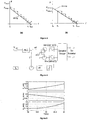
- the power vs frequency characteristic of IPT systems as illustrated in Fig. 2 indicates that small variations in operating frequency around the tuned frequency will cause neither a significant drop in power handling capability nor an increase in circulating energy to exceed the VA rating. This feature of the power-frequency characteristic of IPT systems is utilized in the present invention as described in further detail below.
- the power vs frequency droop characteristic of an IPT system shown in Fig. 2 , illustrates how the frequency can be linearly varied to control the power flow according to the droop control technique of the present invention. It will be seen that in this example, and the other examples provided, a linear variation is not essential i.e. the variation of operating frequency may be in a non-linear proportion to a difference between the current power transfer and a power capability.
- the primary side dictates the frequency of operation in accordance with the droop characteristic, while the pick-up converter simply follows. Both sides operate at the tuned frequency fo only when the system is delivering or receiving the rated power. At all other power levels, the system operates at slightly detuned frequency without violating the VA rating of the system.
- the maximum and minimum frequencies of operation, fmax and fmin correspond to the no load or zero power transfer operation of every primary and pick-up during the forward and reverse power flows, respectively.
- fmax and fmin are set to several hundred hertz above or below the tuned frequency (typically a particular frequency within the range of 10-40 kHz). This relatively small change in frequency ensures that the LCL networks of both the primary and secondary converters remain substantially tuned, yet is large enough in comparison to the tuned frequency f0, to be detected by the primary/secondary controller.
- the frequency is detected and measured using a phase lock loop (PLL) which is also used to synchronize the pickup to the primary.
- PLL phase lock loop
- the output of the PLL is a square wave which is fed into an interrupt pin of a micro controller.
- a timer in the micro controller measures the time between interrupts and by averaging (or more as appropriate) successive interrupts the frequency of operation can be estimated.
- the minimum change that can be detected depends on the speed of the timer in this case with a timer operating at 16 MHz the minimum change that can be detected is 50 Hz. This can be improved with a faster microcontroller.
- the droop control is described by way of example with reference to Fig. 3(a) and 3(b) .
- a pick-up which has a power rating P max, s which is a higher power rating than that of the primary, (being P max,p ) begins to extract power from a primary converter which is idling at f max (i.e. having no load).
- P max,p power rating
- the pick-up controller 4 detects that the primary is idling at f max and begins extracting power, as shown by point B .
- the primary controller 3 continuously or periodically monitors its power output at a sampling rate set by the controller 3.
- the power outputs from the samples are averaged to work out the estimated power output over a time period.
- the sampling rate is determined taking into account the frequency of operation and speed of the microcontroller, and in such a manner that the estimated output power is a good indication of the actual output power to be conveyed to the pickup side by varying the frequency.
- the primary converter reduces the operating frequency to f c , shown by point C , at the next sampling instant.
- the pick-up 2 in turn locks into the 'new' operating frequency, realizes that the frequency is still above f o and, thus, continues to extract more power. This process continues until the operating frequency converges to the tuned frequency f o or point D on the droop characteristic.
- the pick-up 2, detecting that the frequency is f o realizes that the primary 1 is at the maximum possible power level and limits its power intake to P max,p .
- Fig. 3(b) illustrates a situation, where pick-up demand is less than the primary power rating.
- the system settles into a stable operating frequency f D corresponding to the power handling capability P max,s of the secondary, which is slightly greater than the tuned frequency f o which corresponds with the power handling capability P max,P of the primary
- the primary estimates the power output (ie: taken by both pick ups) and accordingly changes its operating frequency, indicating its power capability (or the remaining power that can be supplied) to both pickups. This procedure continues until the primary reaches its power capability.
- the power flow between the primary 1 and the pick-up 2 can be regulated through control of the voltage generated by the pick-up side converter at unity power factor for a given primary voltage.
- the primary converter is driven by a square-wave voltage to generate a constant voltage and keep the track current constant for all loads.
- the voltage generated by the pick-up converter V si is regulated, as desired by way of pulse width modulation.
- the pick-up side converter has two legs (each leg containing two switches). The regulation 11 achieved by driving the legs with a phase-shift ⁇ with respect to each other.
- phase-shift of 0° or 360° degrees generates a square-wave of the maximum possible voltage and corresponds to the maximum power flow in both directions (i.e. 100% duty cycle).
- a phase shift of 180° generates a zero voltage (i.e. 0% duty cycle) as it creates a short circuit by effectively decoupling the pick-up from the track.
- the phase shift changes the effective output voltage, and hence the current, the power output can be controlled through the phase-shift.
- a block diagram of one embodiment of a pick-up droop controller 4 according to the present invention is shown by way of example in Fig. 4 .
- the pick-up controller 4 senses the pick-up coil L Si voltage V sl and uses a phase locked loop (PLL) to determine the frequency of the primary converter.
- PLL phase locked loop
- the error between the operating frequency and the tuned frequency f 0 is fed into a proportional integral (PI) controller to generate the phase-shift ⁇ that is required to extract the desired power.
- Limits are placed on the output of the PI controller to ensure that the phase-shift stays between 0° and 360°. At 180°, no power is transferred while 0° and 360° correspond to the maximum power in the forward and reverse direction, respectively.
- the output current of the pick-up given by Eq. (8) was derived under fully tuned conditions as given by Eq. (3).
- the droop controller varies the frequency of operation to regulate the power intake of the pick-up. Except at rated power, the system therefore operates in a de-tuned state.
- the impact on the magnitude of both real and reactive power due to variation of frequency can be investigated by deriving expressions for system variables under de-tuned conditions.
- Figure 5 illustrates how the real, reactive and apparent components of power vary with the operating frequency.
- both primary and pick-up side converters are assumed to produce rated voltages at relative phase angle of 90°. It is evident from Fig. 5 that the system is operating at unity power factor at the tuned frequency of 20 kHz, as given by Eq. (17).
- the reactive power requirement of the system increases and, consequently, the VA rating also increases.
- the maximum frequency variation adopted by the droop controller is kept within a narrow band, then the increase in both reactive and apparent power is relatively small and will not compromise the VA rating of converters.
- the primary and pick-up side 'droop' controllers were implemented using ATmega-324P model 8-bit microcontrollers, available from Atmel Corporation of San Jose, California.
- the primary side converter supplied by a 200 V DC supply and limited to 1 kW, was controlled to produce a square-wave voltage and maintain a constant track current of 55 A.
- the pick-up was magnetically coupled to the track to either provide or extract power from the primary converter.
- the pick-up side converter was operated from a 200 V DC supply and driven with a 90 degree phase delay with respect to the primary, ensuring that the system operates at unity power factor when tuned in accordance with Eq. (10).
- the pick-up controller operates the pick-up side converter at frequencies dictated by the primary converter, and varies the phase-shift between the two legs of its full bridge converter to control the amount of power being supplied or extracted.
- Fig. 6(a) Simulated steady state waveforms of the system when the pick-up has a lower power rating than that of the primary are shown in Fig. 6(a) .
- the primary operates at slightly off tuned frequency to meet the lower power demand. From the top and third plot, it is evident that the pick-up produces a square wave voltage V si that lags the primary converter voltage V pi . Thus power flows from the primary to the pick-up.
- the track current I T is sinusoidal and constant at approximately 55 A rms.
- Fig. 6(b) shows the experimental results under the same conditions and, as evident, both the simulated and experimental results are very similar.
- Figure 7 shows both (a) simulated and (b) experimental waveforms of the system when the pick-up has a higher power demand than the primary power capability of 1 kW.
- the magnitude of V so was increased by increasing the phase shift ⁇ (i.e. increasing the duty cycle of the secondary inverter).
- the increase in V so is evident from Fig. 7 .
- the primary frequency converges to the tuned frequency to force the pick-up controller to limit its power to maximum of 1 kW.
- the primary controller has maintained a constant track current I T . In this situation, too, both the simulation and experimental results are in very good agreement.
- Figure 8(a) shows the simulated variations in primary power, pick-up power limit and operating frequency with time.
- the pick-up controller is set to a maximum power level of 0.5 kW.
- the pick-up power reference is changed to 1.5 kW, which is greater than the power capability of the primary supply.
- the pick-up controller gradually increases the power intake and the primary controller reduces the operating frequency to indicate that the power intake is reaching the maximum capability of the primary.
- the operating frequency settles at the tuned frequency of 20 kHz and the pick-up limits its power intake to 1 kW despite the higher reference value of 1.5 kW.
- Figure 8(b) shows the experimental results under the same conditions. Apart from slower response time of the pick-up controller, caused by limited processing power of the microcontroller of the prototype, both simulated and experimental results are in good agreement and confirm the validity of the droop control technique.
- Figure 9 shows the measured voltage and current waveforms of the primary and secondary converters of the prototype during the reverse power flow.
- the voltage and current magnitudes of both converters are similar to those corresponding to the forward power flow but, as expected, the primary converter voltage V pi lags the pick-up voltage V so .
- the power flow is once again controlled by varying the magnitude of the pick-up voltage V so , using a phase-shift ⁇ between the legs of the converter to control the duty cycle thereof.
- the measured behaviour of the controller during reverse power flow is shown in Fig. 10 .
- the reference power level of the pick-up converter was initially set to 0.5 kW, and the system deviates below the tuned frequency f 0 , delivering 0.5 kW to the primary.
- the negative reference i.e. operating frequency being below the tuned frequency
- the reference power level of the pick-up was raised to 1.5 kW, exceeding the capability of the primary.
- the secondary controller gradually increases power, preferably in a number of steps, and the primary controller responds by increasing the operating frequency which converges toward the tuned frequency of 20 kHz as it reaches its power limit of 1 kW. At that point, the secondary controller senses that the operating frequency is at the tuned frequency f 0 and limits the power transfer to 1 kW even though the pick-up is capable of supplying more power.
- the primary controller is adapted to periodically or intermittently modulate the frequency of the track current, operating at the tuned frequency f 0 for the majority of time.
- the first example of the invention may be said to maintain the (variable) operating frequency continuously, or at least repetitively monitor the operating frequency
- this second example alternates between the variable operating frequency and the fixed tuned frequency f 0 .
- the primary converter thus relays information with regard to its remaining power capability to the or each pick-up for a short duration while operating at the desired tuned frequency for the remainder of the time to minimise the VA rating of the system.
- the or each pick-up extracts power as dictated by the frequency modulation.
- both the primary and pick-up controllers operate at the tuned frequency except during the moment of the modulation.
- the operation frequency is changed slowly (i.e. ramped up or down in a plurality of incremental steps) during modulation, so that the pick-up is able to stay synchronized (i.e. maintain the same frequency) with the primary.
- ⁇ P represents the difference between the maximum power and the current power being supplied by the primary converter.
- the tuned frequency, f 0 corresponds to the primary outputting maximum power; the maximum and minimum frequencies, f max and f min , correspond to the no load or maximum available power in the forward and reverse directions, respectively.
- f max and f min are set to a few hundred hertz above or below the tuned frequency, as described above with respect to the first example, to ensure that the LCL networks remain substantially tuned to the operating frequency.
- the power flow between the primary and the pick-up can be regulated through control of the voltage generated by the pick-up side converter.
- a block diagram of a suitable controller is shown by way of example in Fig. 12 .
- the voltage generated by the pick-up converter, V so is regulated as desired by controlling ⁇ , the phase shift between switching the legs of the converter and is given by Eq. (18).
- V out is the DC output voltage
- ⁇ T 2 ⁇ f 0
- ⁇ is the phase delay between V pi and V so .
- the primary controller as shown in Fig 11 measures the power ( P Pin ) which is the power that flows out of the primary converter. This is then subtracted from the maximum power that the primary can supply, which gives ⁇ P , the remaining available power that the primary is able to supply.
- the variable ⁇ P is then multiplied by a modulation function which varies the frequency of the primary inverter.
- a frequency modulation preferably occurs periodically once every second, however, when the power flow is rapidly changing the controller will generate jitters (i.e. periodic modulation of the operating frequency) more frequently, to ensure that the system is operating stably.
- the primary and pick-up converters are controlled to produce square wave voltages, V pl and V so .
- the primary is controlled to maintain a constant track current of 45 A. This current is operated at the tuned frequency f 0 , with jitters in the operating frequency occurring periodically, during which the remaining available power is communicated to the or each pick-up of the secondary side via the shift in frequency.
- the pick-up converter is driven with a ⁇ /2 radians phase delay with respect to the primary.
- the pick-up controller is able to vary the phase-shift ⁇ between the legs of the converter, controlling the power being extracted or supplied from the converter by effectively varying the duty cycle of the converter.
- Figure 13 shows the power, frequency and phase shift ( ⁇ ) of the system supplying power from the primary to pick-up.
- the primary controller is set to limit at 2.5 kW
- the pick-up controller is initially set to limit at 1.5 kW. After 100 ms the pick-up limit is increased to 3 kW, which is greater than the 2.5 kW that the primary can supply; this causes the pick-up controller to limit the power that it takes.
- the frequency ( f ) shows that for the majority of the time the system operates at the tuned frequency (20 kHz). However, during the jitters the frequency changes slightly.
- Figure 14 shows the operation of the converter at the high power steady state point.
- the primary converter is operating with a 100% duty cycle, whereas the duty cycle of the secondary converter is substantially less to limit the power drawn by the load to the maximum of 2.5 kW.
- the primary track current I T is a constant sinusoidal at 45 A. It will be appreciated from the foregoing that the present invention in various aspects may be said to consist in a load control method; an IPT power supply adapted to vary frequency to provide an indication of available power; an IPT pick-up adapted to sense variations in the track frequency and limit power transfer accordingly; and/or an IPT system using variations in frequency of the track current to communicate available power from the primary to the or each pick-up.
- the IPT system may be either uni-directional or bi-directional, and may comprise one or more IPT pick-ups.
- a controller according to the present invention may be implemented purely in hardware consisting of one or more components which may include discrete electronic components or integrated circuits.
- the invention may be implemented using programmable hardware components, such as programmable logic devices (PLDs) or field programmable gate arrays (FPGAs), or by software executed by a computing means or processor which may include a microcontroller or general purpose personal computer (PC) programmed accordingly.
- PLDs programmable logic devices
- FPGAs field programmable gate arrays
- PC general purpose personal computer
- the invention would be implemented as an embedded system using a combination of the aforementioned components.
- the present invention thus provides an IPT load control technique which utilizes the power-frequency characteristics of the system to regulate the power flow in both directions while limiting the power, when necessary, without a dedicated communication link.
- the controller is relatively easy to implement, robust, and low in cost without a dedicated communication link. It is applicable for either single or multiple pick-up IPT systems, and ideal for applications such as vehicle-to-grid (V2G) systems, where electric vehicles (EVs) of varying power ratings are to be 'effectively' charged/discharged from a single primary supply.
- V2G vehicle-to-grid
- EVs electric vehicles
- the control technique works with bi-directional systems, so that the "secondary" side or pick-up becomes the "primary" side and the same technique is used.
Landscapes
- Engineering & Computer Science (AREA)
- Power Engineering (AREA)
- Computer Networks & Wireless Communication (AREA)
- Transportation (AREA)
- Mechanical Engineering (AREA)
- Signal Processing (AREA)
- Inverter Devices (AREA)
- Electric Propulsion And Braking For Vehicles (AREA)
- Ac-Ac Conversion (AREA)
Applications Claiming Priority (2)
| Application Number | Priority Date | Filing Date | Title |
|---|---|---|---|
| NZ593764A NZ593764A (en) | 2011-06-27 | 2011-06-27 | Load control for bi-directional inductive power transfer systems |
| PCT/NZ2012/000107 WO2013002651A1 (en) | 2011-06-27 | 2012-06-27 | Load control for bi-directional inductive power transfer systems |
Publications (3)
| Publication Number | Publication Date |
|---|---|
| EP2724448A1 EP2724448A1 (en) | 2014-04-30 |
| EP2724448A4 EP2724448A4 (en) | 2015-05-06 |
| EP2724448B1 true EP2724448B1 (en) | 2019-02-27 |
Family
ID=47424360
Family Applications (1)
| Application Number | Title | Priority Date | Filing Date |
|---|---|---|---|
| EP12804818.8A Active EP2724448B1 (en) | 2011-06-27 | 2012-06-27 | Load control for bi-directional inductive power transfer systems |
Country Status (7)
Families Citing this family (41)
| Publication number | Priority date | Publication date | Assignee | Title |
|---|---|---|---|---|
| NZ593764A (en) * | 2011-06-27 | 2013-12-20 | Auckland Uniservices Ltd | Load control for bi-directional inductive power transfer systems |
| US9716861B1 (en) | 2014-03-07 | 2017-07-25 | Steelcase Inc. | Method and system for facilitating collaboration sessions |
| US10664772B1 (en) | 2014-03-07 | 2020-05-26 | Steelcase Inc. | Method and system for facilitating collaboration sessions |
| PL3407466T3 (pl) * | 2014-03-25 | 2020-06-15 | Koninklijke Philips N.V. | Bezprzewodowe indukcyjne przesyłanie mocy |
| US9955318B1 (en) | 2014-06-05 | 2018-04-24 | Steelcase Inc. | Space guidance and management system and method |
| US9766079B1 (en) | 2014-10-03 | 2017-09-19 | Steelcase Inc. | Method and system for locating resources and communicating within an enterprise |
| US9380682B2 (en) | 2014-06-05 | 2016-06-28 | Steelcase Inc. | Environment optimization for space based on presence and activities |
| US10614694B1 (en) | 2014-06-06 | 2020-04-07 | Steelcase Inc. | Powered furniture assembly |
| US10433646B1 (en) | 2014-06-06 | 2019-10-08 | Steelcaase Inc. | Microclimate control systems and methods |
| US11744376B2 (en) | 2014-06-06 | 2023-09-05 | Steelcase Inc. | Microclimate control systems and methods |
| US9831684B2 (en) * | 2014-08-08 | 2017-11-28 | Texas Instruments Incorporated | Adaptive rectifier and method of operation |
| US12113366B2 (en) | 2014-08-11 | 2024-10-08 | Auckland Uniservices Limited | Resonant frequency compensation |
| US9680312B2 (en) * | 2014-09-10 | 2017-06-13 | Qualcomm Incorporated | System and method for reactive power control in dynamic inductive power transfer systems |
| US9852388B1 (en) | 2014-10-03 | 2017-12-26 | Steelcase, Inc. | Method and system for locating resources and communicating within an enterprise |
| CN104539061B (zh) * | 2015-01-06 | 2018-11-13 | 宁波微鹅电子科技有限公司 | 一种电能发射端、无线电能传输装置和无线电能传输方法 |
| WO2016134319A1 (en) | 2015-02-19 | 2016-08-25 | Enphase Energy, Inc. | Method and apparatus for time-domain droop control with integrated phasor current control |
| DE102015006277A1 (de) | 2015-05-15 | 2015-12-03 | Daimler Ag | Energieübertragungseinrichtung, Kabel hierfür sowie System aus der Energieübertragungseinrichtung, dem Kabel sowie einer Vorrichtung, zu der der mittels der Energieübertragungseinrichtung induktiv übertragene elektrische Strom leitbar ist |
| US10733371B1 (en) | 2015-06-02 | 2020-08-04 | Steelcase Inc. | Template based content preparation system for use with a plurality of space types |
| US10046660B2 (en) | 2015-06-19 | 2018-08-14 | Qualcomm Incorporated | Devices, systems, and methods using reactive power injection for active tuning electric vehicle charging systems |
| CN105141139A (zh) * | 2015-08-03 | 2015-12-09 | 重庆大学 | 用于ipt系统的lcl网络结构及其参数设计方法 |
| CN105186705B (zh) * | 2015-08-04 | 2017-11-10 | 宁波微鹅电子科技有限公司 | 一种高效率的电能发射端、非接触电能传输装置和电能传输方法 |
| CN105391191A (zh) * | 2015-11-17 | 2016-03-09 | 东南大学 | 一种适用于双向无线电能传输系统的功率在线调试方法 |
| US9921726B1 (en) | 2016-06-03 | 2018-03-20 | Steelcase Inc. | Smart workstation method and system |
| WO2018048312A1 (en) | 2016-09-06 | 2018-03-15 | Powerbyproxi Limited | An inductive power transmitter |
| US10651656B2 (en) | 2016-09-14 | 2020-05-12 | Texas Tech University System | UDE-based robust droop control for parallel inverter operation |
| CN106340975B (zh) * | 2016-09-30 | 2019-07-02 | 上海空间电源研究所 | 一种无线电能传输电路及其设计方法 |
| US10264213B1 (en) | 2016-12-15 | 2019-04-16 | Steelcase Inc. | Content amplification system and method |
| CN107618392B (zh) * | 2017-09-29 | 2019-12-31 | 重庆卓谦科技有限公司 | 充电桩自决策的电动汽车充电负荷随机接入控制系统及方法 |
| US9987937B1 (en) * | 2017-12-20 | 2018-06-05 | The Florida International University Board Of Trustees | Autonomous two-layer predictive controller for bidirectional inductive power transfer in EV applications |
| US11626811B2 (en) * | 2018-01-25 | 2023-04-11 | Auckland Uniservices Limited | Multi-level modular converter |
| EP3784517B1 (en) * | 2018-04-23 | 2023-02-15 | ABB E-mobility B.V. | A power transfer system for electric vehicles and a control method thereof |
| CN109327065B (zh) | 2018-12-06 | 2020-02-21 | 华为技术有限公司 | 无线充电系统的接收端、方法、用电终端、发射端及系统 |
| KR102155627B1 (ko) * | 2018-12-28 | 2020-09-16 | 현대엘리베이터주식회사 | 엘리베이터 무선전력 제어 장치 |
| JP6823112B2 (ja) * | 2019-06-10 | 2021-01-27 | 株式会社京三製作所 | 電力変換装置 |
| WO2021033131A1 (en) | 2019-08-16 | 2021-02-25 | Auckland Uniservices Limited | Vehicle-grid-home power interface |
| CN111355307B (zh) * | 2020-03-15 | 2022-09-09 | 东南大学 | 一种基于pi控制器优化的bd-wpt系统功率协调控制方法 |
| US12118178B1 (en) | 2020-04-08 | 2024-10-15 | Steelcase Inc. | Wayfinding services method and apparatus |
| US11984739B1 (en) | 2020-07-31 | 2024-05-14 | Steelcase Inc. | Remote power systems, apparatus and methods |
| US12005249B2 (en) * | 2021-02-12 | 2024-06-11 | Medtronic, Inc. | Method for regulating TETS power transfer |
| US12019415B2 (en) | 2022-02-24 | 2024-06-25 | Toyota Motor North America, Inc. | Grouping electric transports for an electric grid |
| DE102022203233A1 (de) * | 2022-04-01 | 2023-10-05 | Robert Bosch Gesellschaft mit beschränkter Haftung | Ladeschaltung und Verfahren zum Aufladen einer Traktionsbatterie, Elektrofahrzeug |
Family Cites Families (41)
| Publication number | Priority date | Publication date | Assignee | Title |
|---|---|---|---|---|
| NO913368D0 (no) * | 1991-08-27 | 1991-08-27 | Julius Hartai | Frekvensmodulert driver med parallell-resonans. |
| KR950701778A (ko) * | 1992-05-10 | 1995-04-28 | 마크 버게스 | 비접촉 전력배전 시스템(a non-contact power distribution system) |
| DE4442677A1 (de) * | 1994-11-30 | 1996-06-05 | Siemens Ag | Verfahren und Anordnung zum Versorgen eines elektrischen Verbrauchers mit einer elektrischen Versorgungsspannung oder einem elektrischen Versorgungsstrom über Funk |
| JPH08265986A (ja) * | 1995-03-20 | 1996-10-11 | Sumitomo Electric Ind Ltd | インダクティブ充電方法 |
| WO1998050993A1 (en) * | 1997-05-06 | 1998-11-12 | Auckland Uniservices Limited | Inductive power transfer across an extended gap |
| US7212414B2 (en) * | 1999-06-21 | 2007-05-01 | Access Business Group International, Llc | Adaptive inductive power supply |
| JP4614961B2 (ja) | 2003-05-23 | 2011-01-19 | オークランド ユニサービシズ リミテッド | 誘導結合電力伝達システムを制御する方法および装置 |
| NZ528542A (en) | 2003-09-29 | 2006-09-29 | Auckland Uniservices Ltd | Inductively-powered power transfer system with one or more, independently controlled loads |
| KR100853889B1 (ko) | 2005-07-29 | 2008-08-25 | 엘에스전선 주식회사 | 무 접점 충전 배터리 및 충전기, 이들을 포함하는 배터리충전 세트, 및 충전제어 방법 |
| CN101292415B (zh) * | 2005-10-09 | 2010-12-29 | 崇贸科技股份有限公司 | 测量来自功率转换器初级侧的输出电流的设备及方法 |
| JP4209437B2 (ja) * | 2006-11-10 | 2009-01-14 | 三菱重工業株式会社 | 移動体の非接触給電装置及びその保護装置 |
| TWI339471B (en) * | 2006-12-27 | 2011-03-21 | Ind Tech Res Inst | Non-contact power supply having built-in coupling detection device and coupling detection method thereof |
| JP4494426B2 (ja) | 2007-02-16 | 2010-06-30 | セイコーエプソン株式会社 | 送電制御装置、受電制御装置、無接点電力伝送システム、送電装置、受電装置および電子機器 |
| JP4308858B2 (ja) * | 2007-02-16 | 2009-08-05 | セイコーエプソン株式会社 | 送電制御装置、受電制御装置、無接点電力伝送システム、送電装置、受電装置および電子機器 |
| EP2195905A4 (en) | 2007-09-17 | 2017-03-22 | Qualcomm Incorporated | High efficiency and power transfer in wireless power magnetic resonators |
| JP5556002B2 (ja) | 2008-01-09 | 2014-07-23 | セイコーエプソン株式会社 | 送電制御装置、送電装置、無接点電力伝送システムおよび電子機器 |
| CN102084442B (zh) * | 2008-03-17 | 2013-12-04 | 鲍尔马特技术有限公司 | 感应传输系统 |
| JP2009268181A (ja) | 2008-04-22 | 2009-11-12 | Olympus Corp | エネルギー供給装置 |
| ES2326780B2 (es) | 2008-05-29 | 2010-06-16 | Fundacion Circe - Centro De Investigacion De Recursos Y Consumos Energeticos | Metodo automatico de control de un sistema de transferencia de potencia con acoplamiento inductivo en alta frecuencia. |
| CN104539027A (zh) * | 2008-07-09 | 2015-04-22 | 捷通国际有限公司 | 无线充电系统 |
| US7903435B2 (en) * | 2008-08-05 | 2011-03-08 | System General Corp. | Switching controller having switching frequency hopping for power converter |
| EP4342723A1 (en) * | 2008-08-18 | 2024-03-27 | Christopher B. Austin | Vehicular battery charger, charging system, and method |
| US8299652B2 (en) * | 2008-08-20 | 2012-10-30 | Intel Corporation | Wireless power transfer apparatus and method thereof |
| CN102165667B (zh) * | 2008-09-26 | 2014-09-03 | 株式会社村田制作所 | 无接点充电系统 |
| US8692410B2 (en) * | 2008-09-27 | 2014-04-08 | Witricity Corporation | Wireless energy transfer with frequency hopping |
| JP5375032B2 (ja) | 2008-11-04 | 2013-12-25 | 株式会社豊田自動織機 | 非接触電力伝送装置及び非接触電力伝送装置の設計方法 |
| JP2010110533A (ja) | 2008-11-07 | 2010-05-20 | Olympus Corp | 無線給電システム |
| WO2010062201A1 (en) * | 2008-11-26 | 2010-06-03 | Auckland Uniservices Limited | Primary-side power control for inductive power transfer |
| JP2010198875A (ja) * | 2009-02-24 | 2010-09-09 | Panasonic Electric Works Co Ltd | 放電灯点灯装置及び照明器具 |
| CN201365144Y (zh) * | 2009-03-02 | 2009-12-16 | 李植扬 | 感应式供电装置 |
| EP2406655B1 (en) | 2009-03-09 | 2019-01-30 | NuCurrent, Inc. | System and method for wireless power transfer in implantable medical devices |
| JP5993304B2 (ja) * | 2009-09-09 | 2016-09-14 | オークランド ユニサービシズ リミテッドAuckland Uniservices Limited | 誘導電力伝送システムにおける電力需要管理 |
| JP5174769B2 (ja) * | 2009-09-11 | 2013-04-03 | 三菱電機株式会社 | 非接触伝送装置 |
| JP5664018B2 (ja) * | 2009-10-30 | 2015-02-04 | Tdk株式会社 | ワイヤレス給電装置、ワイヤレス電力伝送システムおよびそれらを利用したテーブルと卓上ランプ |
| EP2515414A4 (en) | 2009-11-18 | 2016-04-06 | Toshiba Kk | DEVICE FOR WIRELESS POWER TRANSMISSION |
| KR101730824B1 (ko) * | 2009-11-30 | 2017-04-27 | 삼성전자주식회사 | 무선 전력 트랜시버 및 무선 전력 시스템 |
| JP2011125184A (ja) | 2009-12-14 | 2011-06-23 | Toyota Motor Corp | 非接触給電設備、非接触受電装置、および非接触給電システム |
| US8143746B2 (en) * | 2009-12-21 | 2012-03-27 | Alcatel Lucent | Automatic tuning for wireless power transfer |
| CN201733141U (zh) * | 2010-06-10 | 2011-02-02 | 罗秀玲 | 电子装置 |
| US8829726B2 (en) * | 2010-07-02 | 2014-09-09 | Tdk Corporation | Wireless power feeder and wireless power transmission system |
| NZ593764A (en) * | 2011-06-27 | 2013-12-20 | Auckland Uniservices Ltd | Load control for bi-directional inductive power transfer systems |
-
2011
- 2011-06-27 NZ NZ593764A patent/NZ593764A/en not_active Application Discontinuation
-
2012
- 2012-06-27 KR KR1020147001559A patent/KR101971203B1/ko active Active
- 2012-06-27 JP JP2014518471A patent/JP6283309B2/ja active Active
- 2012-06-27 EP EP12804818.8A patent/EP2724448B1/en active Active
- 2012-06-27 WO PCT/NZ2012/000107 patent/WO2013002651A1/en active Application Filing
- 2012-06-27 CN CN201710591343.3A patent/CN107472056B/zh active Active
- 2012-06-27 CN CN201280030503.2A patent/CN103814503B/zh active Active
- 2012-06-27 US US14/127,882 patent/US9660702B2/en active Active
-
2017
- 2017-04-13 US US15/487,267 patent/US10243409B2/en active Active
-
2018
- 2018-01-26 JP JP2018011056A patent/JP6991867B2/ja active Active
Non-Patent Citations (1)
| Title |
|---|
| None * |
Also Published As
| Publication number | Publication date |
|---|---|
| JP6991867B2 (ja) | 2022-01-13 |
| CN103814503B (zh) | 2017-07-28 |
| KR20140103248A (ko) | 2014-08-26 |
| EP2724448A1 (en) | 2014-04-30 |
| JP2018085925A (ja) | 2018-05-31 |
| EP2724448A4 (en) | 2015-05-06 |
| CN103814503A (zh) | 2014-05-21 |
| JP2014521288A (ja) | 2014-08-25 |
| US10243409B2 (en) | 2019-03-26 |
| CN107472056A (zh) | 2017-12-15 |
| US20170229918A1 (en) | 2017-08-10 |
| JP6283309B2 (ja) | 2018-02-21 |
| US9660702B2 (en) | 2017-05-23 |
| NZ593764A (en) | 2013-12-20 |
| US20140203659A1 (en) | 2014-07-24 |
| WO2013002651A1 (en) | 2013-01-03 |
| KR101971203B1 (ko) | 2019-04-22 |
| CN107472056B (zh) | 2020-08-21 |
Similar Documents
| Publication | Publication Date | Title |
|---|---|---|
| EP2724448B1 (en) | Load control for bi-directional inductive power transfer systems | |
| US10432026B2 (en) | Primary-side power control for inductive power transfer | |
| Madawala et al. | A power–frequency controller for bidirectional inductive power transfer systems | |
| Li et al. | Active and reactive currents decomposition-based control of angle and magnitude of current for a parallel multiinverter IPT system | |
| EP2947749B1 (en) | Non-contact power transmitting and receiving system | |
| Hao et al. | A parallel topology for inductive power transfer power supplies | |
| WO2010062201A1 (en) | Primary-side power control for inductive power transfer | |
| WO2015128942A1 (ja) | 非接触給電システム及び送電装置 | |
| CN102868234A (zh) | 非接触供电设备 | |
| CN107148712A (zh) | 谐振频率补偿 | |
| CN104160577A (zh) | 功率变换器电路,电源系统和方法 | |
| CN102222937A (zh) | 一种光伏并网逆变器及其并网控制方法 | |
| JP2018528743A (ja) | 無線電力伝送システム及びその駆動方法 | |
| US11316375B2 (en) | Control of active rectification in wireless power systems | |
| JP2017060328A (ja) | 非接触受電装置及び電力伝送システム | |
| Neath et al. | A new controller for bi-directional inductive power transfer systems | |
| Neath et al. | Frequency jitter control of a multiple pick-up Bidirectional Inductive Power Transfer system | |
| JP2009254031A (ja) | 非接触給電装置 | |
| CN104685752B (zh) | 具有谐振变换器的电路布置和用于运行谐振变换器的方法 | |
| Sasikumar et al. | An Efficient Resonant Transmitter with Single Stage Boost Receiver Topology for Wireless Power Transfer in Electric Vehicle | |
| US20210143680A1 (en) | Non-contact power supply system and power transmission device | |
| NZ573241A (en) | Estimating pickup output voltage by voltage across the primary conductive path |
Legal Events
| Date | Code | Title | Description |
|---|---|---|---|
| PUAI | Public reference made under article 153(3) epc to a published international application that has entered the european phase |
Free format text: ORIGINAL CODE: 0009012 |
|
| 17P | Request for examination filed |
Effective date: 20140124 |
|
| AK | Designated contracting states |
Kind code of ref document: A1 Designated state(s): AL AT BE BG CH CY CZ DE DK EE ES FI FR GB GR HR HU IE IS IT LI LT LU LV MC MK MT NL NO PL PT RO RS SE SI SK SM TR |
|
| DAX | Request for extension of the european patent (deleted) | ||
| RA4 | Supplementary search report drawn up and despatched (corrected) |
Effective date: 20150409 |
|
| RIC1 | Information provided on ipc code assigned before grant |
Ipc: H02J 17/00 20060101AFI20150401BHEP Ipc: B60L 9/00 20060101ALN20150401BHEP Ipc: H02J 7/00 20060101ALI20150401BHEP |
|
| RAP1 | Party data changed (applicant data changed or rights of an application transferred) |
Owner name: AUCKLAND UNISERVICES LIMITED |
|
| STAA | Information on the status of an ep patent application or granted ep patent |
Free format text: STATUS: EXAMINATION IS IN PROGRESS |
|
| 17Q | First examination report despatched |
Effective date: 20170130 |
|
| 111L | Licence recorded |
Designated state(s): AL AT BE BG CH CY CZ DE DK EE ES FI FR GB GR HR HU IE IS IT LT LU LV MC MK MT NL NO PL PT RO RS SE SI SK SM TR Free format text: EXCLUSIVE LICENSE Name of requester: QUALCOMM INCORPORATED, US Effective date: 20171018 |
|
| GRAP | Despatch of communication of intention to grant a patent |
Free format text: ORIGINAL CODE: EPIDOSNIGR1 |
|
| STAA | Information on the status of an ep patent application or granted ep patent |
Free format text: STATUS: GRANT OF PATENT IS INTENDED |
|
| RIC1 | Information provided on ipc code assigned before grant |
Ipc: B60L 9/00 20060101ALN20180412BHEP Ipc: H02J 50/00 20160101AFI20180412BHEP Ipc: H02J 7/00 20060101ALI20180412BHEP |
|
| RIC1 | Information provided on ipc code assigned before grant |
Ipc: H02J 50/00 20160101AFI20180419BHEP Ipc: H02J 7/00 20060101ALI20180419BHEP Ipc: B60L 9/00 20060101ALN20180419BHEP |
|
| INTG | Intention to grant announced |
Effective date: 20180508 |
|
| GRAJ | Information related to disapproval of communication of intention to grant by the applicant or resumption of examination proceedings by the epo deleted |
Free format text: ORIGINAL CODE: EPIDOSDIGR1 |
|
| STAA | Information on the status of an ep patent application or granted ep patent |
Free format text: STATUS: EXAMINATION IS IN PROGRESS |
|
| REG | Reference to a national code |
Ref country code: DE Ref legal event code: R079 Ref document number: 602012057198 Country of ref document: DE Free format text: PREVIOUS MAIN CLASS: H02J0017000000 Ipc: H02J0050000000 |
|
| GRAJ | Information related to disapproval of communication of intention to grant by the applicant or resumption of examination proceedings by the epo deleted |
Free format text: ORIGINAL CODE: EPIDOSDIGR1 |
|
| GRAS | Grant fee paid |
Free format text: ORIGINAL CODE: EPIDOSNIGR3 |
|
| STAA | Information on the status of an ep patent application or granted ep patent |
Free format text: STATUS: GRANT OF PATENT IS INTENDED |
|
| GRAP | Despatch of communication of intention to grant a patent |
Free format text: ORIGINAL CODE: EPIDOSNIGR1 |
|
| INTC | Intention to grant announced (deleted) | ||
| RIC1 | Information provided on ipc code assigned before grant |
Ipc: H02J 7/00 20060101ALI20181002BHEP Ipc: B60L 9/00 20060101ALN20181002BHEP Ipc: H02J 50/00 20160101AFI20181002BHEP |
|
| INTG | Intention to grant announced |
Effective date: 20181017 |
|
| GRAA | (expected) grant |
Free format text: ORIGINAL CODE: 0009210 |
|
| STAA | Information on the status of an ep patent application or granted ep patent |
Free format text: STATUS: THE PATENT HAS BEEN GRANTED |
|
| RIC1 | Information provided on ipc code assigned before grant |
Ipc: B60L 9/00 20190101ALN20181002BHEP Ipc: H02J 50/00 20160101AFI20181002BHEP Ipc: H02J 7/00 20060101ALI20181002BHEP |
|
| 111L | Licence recorded |
Designated state(s): AL AT BE BG CH CY CZ DE DK EE ES FI FR GB GR HR HU IE IS IT LT LU LV MC MK MT NL NO PL PT RO RS SE SI SK SM TR Free format text: EXCLUSIVE LICENSE Name of requester: QUALCOMM INCORPORATED, US Effective date: 20171018 |
|
| AK | Designated contracting states |
Kind code of ref document: B1 Designated state(s): AL AT BE BG CH CY CZ DE DK EE ES FI FR GB GR HR HU IE IS IT LI LT LU LV MC MK MT NL NO PL PT RO RS SE SI SK SM TR |
|
| REG | Reference to a national code |
Ref country code: GB Ref legal event code: FG4D |
|
| REG | Reference to a national code |
Ref country code: CH Ref legal event code: EP |
|
| REG | Reference to a national code |
Ref country code: AT Ref legal event code: REF Ref document number: 1102731 Country of ref document: AT Kind code of ref document: T Effective date: 20190315 |
|
| REG | Reference to a national code |
Ref country code: IE Ref legal event code: FG4D |
|
| REG | Reference to a national code |
Ref country code: DE Ref legal event code: R096 Ref document number: 602012057198 Country of ref document: DE |
|
| RAP2 | Party data changed (patent owner data changed or rights of a patent transferred) |
Owner name: AUCKLAND UNISERVICES LIMITED |
|
| REG | Reference to a national code |
Ref country code: NL Ref legal event code: MP Effective date: 20190227 |
|
| REG | Reference to a national code |
Ref country code: LT Ref legal event code: MG4D |
|
| PG25 | Lapsed in a contracting state [announced via postgrant information from national office to epo] |
Ref country code: PT Free format text: LAPSE BECAUSE OF FAILURE TO SUBMIT A TRANSLATION OF THE DESCRIPTION OR TO PAY THE FEE WITHIN THE PRESCRIBED TIME-LIMIT Effective date: 20190627 Ref country code: SE Free format text: LAPSE BECAUSE OF FAILURE TO SUBMIT A TRANSLATION OF THE DESCRIPTION OR TO PAY THE FEE WITHIN THE PRESCRIBED TIME-LIMIT Effective date: 20190227 Ref country code: FI Free format text: LAPSE BECAUSE OF FAILURE TO SUBMIT A TRANSLATION OF THE DESCRIPTION OR TO PAY THE FEE WITHIN THE PRESCRIBED TIME-LIMIT Effective date: 20190227 Ref country code: NO Free format text: LAPSE BECAUSE OF FAILURE TO SUBMIT A TRANSLATION OF THE DESCRIPTION OR TO PAY THE FEE WITHIN THE PRESCRIBED TIME-LIMIT Effective date: 20190527 Ref country code: LT Free format text: LAPSE BECAUSE OF FAILURE TO SUBMIT A TRANSLATION OF THE DESCRIPTION OR TO PAY THE FEE WITHIN THE PRESCRIBED TIME-LIMIT Effective date: 20190227 Ref country code: NL Free format text: LAPSE BECAUSE OF FAILURE TO SUBMIT A TRANSLATION OF THE DESCRIPTION OR TO PAY THE FEE WITHIN THE PRESCRIBED TIME-LIMIT Effective date: 20190227 |
|
| PG25 | Lapsed in a contracting state [announced via postgrant information from national office to epo] |
Ref country code: IS Free format text: LAPSE BECAUSE OF FAILURE TO SUBMIT A TRANSLATION OF THE DESCRIPTION OR TO PAY THE FEE WITHIN THE PRESCRIBED TIME-LIMIT Effective date: 20190627 Ref country code: BG Free format text: LAPSE BECAUSE OF FAILURE TO SUBMIT A TRANSLATION OF THE DESCRIPTION OR TO PAY THE FEE WITHIN THE PRESCRIBED TIME-LIMIT Effective date: 20190527 Ref country code: GR Free format text: LAPSE BECAUSE OF FAILURE TO SUBMIT A TRANSLATION OF THE DESCRIPTION OR TO PAY THE FEE WITHIN THE PRESCRIBED TIME-LIMIT Effective date: 20190528 Ref country code: LV Free format text: LAPSE BECAUSE OF FAILURE TO SUBMIT A TRANSLATION OF THE DESCRIPTION OR TO PAY THE FEE WITHIN THE PRESCRIBED TIME-LIMIT Effective date: 20190227 Ref country code: HR Free format text: LAPSE BECAUSE OF FAILURE TO SUBMIT A TRANSLATION OF THE DESCRIPTION OR TO PAY THE FEE WITHIN THE PRESCRIBED TIME-LIMIT Effective date: 20190227 Ref country code: RS Free format text: LAPSE BECAUSE OF FAILURE TO SUBMIT A TRANSLATION OF THE DESCRIPTION OR TO PAY THE FEE WITHIN THE PRESCRIBED TIME-LIMIT Effective date: 20190227 |
|
| REG | Reference to a national code |
Ref country code: AT Ref legal event code: MK05 Ref document number: 1102731 Country of ref document: AT Kind code of ref document: T Effective date: 20190227 |
|
| PG25 | Lapsed in a contracting state [announced via postgrant information from national office to epo] |
Ref country code: RO Free format text: LAPSE BECAUSE OF FAILURE TO SUBMIT A TRANSLATION OF THE DESCRIPTION OR TO PAY THE FEE WITHIN THE PRESCRIBED TIME-LIMIT Effective date: 20190227 Ref country code: AL Free format text: LAPSE BECAUSE OF FAILURE TO SUBMIT A TRANSLATION OF THE DESCRIPTION OR TO PAY THE FEE WITHIN THE PRESCRIBED TIME-LIMIT Effective date: 20190227 Ref country code: CZ Free format text: LAPSE BECAUSE OF FAILURE TO SUBMIT A TRANSLATION OF THE DESCRIPTION OR TO PAY THE FEE WITHIN THE PRESCRIBED TIME-LIMIT Effective date: 20190227 Ref country code: IT Free format text: LAPSE BECAUSE OF FAILURE TO SUBMIT A TRANSLATION OF THE DESCRIPTION OR TO PAY THE FEE WITHIN THE PRESCRIBED TIME-LIMIT Effective date: 20190227 Ref country code: EE Free format text: LAPSE BECAUSE OF FAILURE TO SUBMIT A TRANSLATION OF THE DESCRIPTION OR TO PAY THE FEE WITHIN THE PRESCRIBED TIME-LIMIT Effective date: 20190227 Ref country code: DK Free format text: LAPSE BECAUSE OF FAILURE TO SUBMIT A TRANSLATION OF THE DESCRIPTION OR TO PAY THE FEE WITHIN THE PRESCRIBED TIME-LIMIT Effective date: 20190227 Ref country code: ES Free format text: LAPSE BECAUSE OF FAILURE TO SUBMIT A TRANSLATION OF THE DESCRIPTION OR TO PAY THE FEE WITHIN THE PRESCRIBED TIME-LIMIT Effective date: 20190227 Ref country code: SK Free format text: LAPSE BECAUSE OF FAILURE TO SUBMIT A TRANSLATION OF THE DESCRIPTION OR TO PAY THE FEE WITHIN THE PRESCRIBED TIME-LIMIT Effective date: 20190227 |
|
| REG | Reference to a national code |
Ref country code: DE Ref legal event code: R097 Ref document number: 602012057198 Country of ref document: DE |
|
| PG25 | Lapsed in a contracting state [announced via postgrant information from national office to epo] |
Ref country code: PL Free format text: LAPSE BECAUSE OF FAILURE TO SUBMIT A TRANSLATION OF THE DESCRIPTION OR TO PAY THE FEE WITHIN THE PRESCRIBED TIME-LIMIT Effective date: 20190227 Ref country code: SM Free format text: LAPSE BECAUSE OF FAILURE TO SUBMIT A TRANSLATION OF THE DESCRIPTION OR TO PAY THE FEE WITHIN THE PRESCRIBED TIME-LIMIT Effective date: 20190227 |
|
| PG25 | Lapsed in a contracting state [announced via postgrant information from national office to epo] |
Ref country code: AT Free format text: LAPSE BECAUSE OF FAILURE TO SUBMIT A TRANSLATION OF THE DESCRIPTION OR TO PAY THE FEE WITHIN THE PRESCRIBED TIME-LIMIT Effective date: 20190227 |
|
| PLBE | No opposition filed within time limit |
Free format text: ORIGINAL CODE: 0009261 |
|
| STAA | Information on the status of an ep patent application or granted ep patent |
Free format text: STATUS: NO OPPOSITION FILED WITHIN TIME LIMIT |
|
| PG25 | Lapsed in a contracting state [announced via postgrant information from national office to epo] |
Ref country code: MC Free format text: LAPSE BECAUSE OF FAILURE TO SUBMIT A TRANSLATION OF THE DESCRIPTION OR TO PAY THE FEE WITHIN THE PRESCRIBED TIME-LIMIT Effective date: 20190227 |
|
| REG | Reference to a national code |
Ref country code: CH Ref legal event code: PL |
|
| 26N | No opposition filed |
Effective date: 20191128 |
|
| PG25 | Lapsed in a contracting state [announced via postgrant information from national office to epo] |
Ref country code: SI Free format text: LAPSE BECAUSE OF FAILURE TO SUBMIT A TRANSLATION OF THE DESCRIPTION OR TO PAY THE FEE WITHIN THE PRESCRIBED TIME-LIMIT Effective date: 20190227 |
|
| REG | Reference to a national code |
Ref country code: BE Ref legal event code: MM Effective date: 20190630 |
|
| PG25 | Lapsed in a contracting state [announced via postgrant information from national office to epo] |
Ref country code: TR Free format text: LAPSE BECAUSE OF FAILURE TO SUBMIT A TRANSLATION OF THE DESCRIPTION OR TO PAY THE FEE WITHIN THE PRESCRIBED TIME-LIMIT Effective date: 20190227 |
|
| PG25 | Lapsed in a contracting state [announced via postgrant information from national office to epo] |
Ref country code: IE Free format text: LAPSE BECAUSE OF NON-PAYMENT OF DUE FEES Effective date: 20190627 |
|
| PG25 | Lapsed in a contracting state [announced via postgrant information from national office to epo] |
Ref country code: LU Free format text: LAPSE BECAUSE OF NON-PAYMENT OF DUE FEES Effective date: 20190627 Ref country code: BE Free format text: LAPSE BECAUSE OF NON-PAYMENT OF DUE FEES Effective date: 20190630 Ref country code: LI Free format text: LAPSE BECAUSE OF NON-PAYMENT OF DUE FEES Effective date: 20190630 Ref country code: CH Free format text: LAPSE BECAUSE OF NON-PAYMENT OF DUE FEES Effective date: 20190630 |
|
| PG25 | Lapsed in a contracting state [announced via postgrant information from national office to epo] |
Ref country code: CY Free format text: LAPSE BECAUSE OF FAILURE TO SUBMIT A TRANSLATION OF THE DESCRIPTION OR TO PAY THE FEE WITHIN THE PRESCRIBED TIME-LIMIT Effective date: 20190227 |
|
| PG25 | Lapsed in a contracting state [announced via postgrant information from national office to epo] |
Ref country code: MT Free format text: LAPSE BECAUSE OF FAILURE TO SUBMIT A TRANSLATION OF THE DESCRIPTION OR TO PAY THE FEE WITHIN THE PRESCRIBED TIME-LIMIT Effective date: 20190227 Ref country code: HU Free format text: LAPSE BECAUSE OF FAILURE TO SUBMIT A TRANSLATION OF THE DESCRIPTION OR TO PAY THE FEE WITHIN THE PRESCRIBED TIME-LIMIT; INVALID AB INITIO Effective date: 20120627 |
|
| PG25 | Lapsed in a contracting state [announced via postgrant information from national office to epo] |
Ref country code: MK Free format text: LAPSE BECAUSE OF FAILURE TO SUBMIT A TRANSLATION OF THE DESCRIPTION OR TO PAY THE FEE WITHIN THE PRESCRIBED TIME-LIMIT Effective date: 20190227 |
|
| P01 | Opt-out of the competence of the unified patent court (upc) registered |
Effective date: 20230529 |
|
| PGFP | Annual fee paid to national office [announced via postgrant information from national office to epo] |
Ref country code: DE Payment date: 20250512 Year of fee payment: 14 |
|
| PGFP | Annual fee paid to national office [announced via postgrant information from national office to epo] |
Ref country code: GB Payment date: 20250513 Year of fee payment: 14 |
|
| PGFP | Annual fee paid to national office [announced via postgrant information from national office to epo] |
Ref country code: FR Payment date: 20250509 Year of fee payment: 14 |