EP2724037B1 - Chapeau de palier de vilebrequin avec piliers optimises - Google Patents
Chapeau de palier de vilebrequin avec piliers optimises Download PDFInfo
- Publication number
- EP2724037B1 EP2724037B1 EP12713226.4A EP12713226A EP2724037B1 EP 2724037 B1 EP2724037 B1 EP 2724037B1 EP 12713226 A EP12713226 A EP 12713226A EP 2724037 B1 EP2724037 B1 EP 2724037B1
- Authority
- EP
- European Patent Office
- Prior art keywords
- bearing cap
- pillar
- grooves
- crankshaft
- fixing
- Prior art date
- Legal status (The legal status is an assumption and is not a legal conclusion. Google has not performed a legal analysis and makes no representation as to the accuracy of the status listed.)
- Active
Links
Images

Classifications
-
- F—MECHANICAL ENGINEERING; LIGHTING; HEATING; WEAPONS; BLASTING
- F16—ENGINEERING ELEMENTS AND UNITS; GENERAL MEASURES FOR PRODUCING AND MAINTAINING EFFECTIVE FUNCTIONING OF MACHINES OR INSTALLATIONS; THERMAL INSULATION IN GENERAL
- F16C—SHAFTS; FLEXIBLE SHAFTS; ELEMENTS OR CRANKSHAFT MECHANISMS; ROTARY BODIES OTHER THAN GEARING ELEMENTS; BEARINGS
- F16C9/00—Bearings for crankshafts or connecting-rods; Attachment of connecting-rods
- F16C9/02—Crankshaft bearings
-
- F—MECHANICAL ENGINEERING; LIGHTING; HEATING; WEAPONS; BLASTING
- F02—COMBUSTION ENGINES; HOT-GAS OR COMBUSTION-PRODUCT ENGINE PLANTS
- F02F—CYLINDERS, PISTONS OR CASINGS, FOR COMBUSTION ENGINES; ARRANGEMENTS OF SEALINGS IN COMBUSTION ENGINES
- F02F7/00—Casings, e.g. crankcases
-
- F—MECHANICAL ENGINEERING; LIGHTING; HEATING; WEAPONS; BLASTING
- F16—ENGINEERING ELEMENTS AND UNITS; GENERAL MEASURES FOR PRODUCING AND MAINTAINING EFFECTIVE FUNCTIONING OF MACHINES OR INSTALLATIONS; THERMAL INSULATION IN GENERAL
- F16C—SHAFTS; FLEXIBLE SHAFTS; ELEMENTS OR CRANKSHAFT MECHANISMS; ROTARY BODIES OTHER THAN GEARING ELEMENTS; BEARINGS
- F16C35/00—Rigid support of bearing units; Housings, e.g. caps, covers
-
- F—MECHANICAL ENGINEERING; LIGHTING; HEATING; WEAPONS; BLASTING
- F16—ENGINEERING ELEMENTS AND UNITS; GENERAL MEASURES FOR PRODUCING AND MAINTAINING EFFECTIVE FUNCTIONING OF MACHINES OR INSTALLATIONS; THERMAL INSULATION IN GENERAL
- F16C—SHAFTS; FLEXIBLE SHAFTS; ELEMENTS OR CRANKSHAFT MECHANISMS; ROTARY BODIES OTHER THAN GEARING ELEMENTS; BEARINGS
- F16C2326/00—Articles relating to transporting
- F16C2326/20—Land vehicles
- F16C2326/28—Bicycle propulsion, e.g. crankshaft and its support
-
- F—MECHANICAL ENGINEERING; LIGHTING; HEATING; WEAPONS; BLASTING
- F16—ENGINEERING ELEMENTS AND UNITS; GENERAL MEASURES FOR PRODUCING AND MAINTAINING EFFECTIVE FUNCTIONING OF MACHINES OR INSTALLATIONS; THERMAL INSULATION IN GENERAL
- F16C—SHAFTS; FLEXIBLE SHAFTS; ELEMENTS OR CRANKSHAFT MECHANISMS; ROTARY BODIES OTHER THAN GEARING ELEMENTS; BEARINGS
- F16C2360/00—Engines or pumps
- F16C2360/22—Internal combustion engines
Definitions
- the present invention relates to the crankshaft bearing caps and more particularly the fixing of these bearing caps.
- the invention also relates to internal combustion engines comprising a crankshaft whose axis is surrounded by a bearing and a bearing cap.
- crankshaft bearing cap is subjected to significant stresses, in particular in the zone in the vicinity of the pillars for fixing the bearing cap and at the level of said pillars themselves, which constraints can cause failure primers and cause failure of the bearing cap. the room and as a result of the engine. It is therefore necessary to strengthen said cap and strengthen its fatigue resistance. Since the part comes from casting of cast iron, this generally results in increasing the mass of the bearing cap and in part that of the pillars, which goes against the efforts to reduce the mass of each component to reduce the energy consumption of the engine and / or the vehicle or to favor more expensive materials for molding said bearing cap.
- the publication FR2878588 B1 discloses a crankshaft pillar cap having the shape of a half-cylinder whose axis coincides with the axis of the crankshaft, having an external convex surface and having at each of its ends a fixing pillar, the connecting zone between the outer surface of the half-cylinder and said attachment pillars is geometrically optimized to improve the fatigue resistance while decreasing the mass.
- the document does not disclose any embodiment rule concerning the fixing pillar.
- the publication US 2010 / 180853- A1 discloses a bearing cap having two pillars at each end of said cap, each pillar having a substantially oval upper surface and two vertical grooves.
- the publication WO 2007/033139 - A2 has a bearing cap with four fixing pillars.
- An object of the invention is an optimization of the shape of the bearing cap abutments and the subject of the invention is a bearing cap having a half-cylinder shape comprising diametrically opposite fixing pillars with an optimized profile with a reduction of the mass of the pillars while improving the fatigue resistance of the bearing cap.
- crankshaft bearing cap according to the invention is described in claim 1.
- the crankshaft bearing cap has a semi-cylindrical shape having at each of its ends a fixing pillar in the form of a substantially oval column slightly flared at the base which has at least two lateral grooves on at least a portion of the height of the pillar. Said grooves reduce the mass of the fixing pillars and contribute to the improvement of their fatigue strength.
- the fixing pillars comprise at least two grooves which are arranged outside a vertical support cylinder whose base is equal to the bearing surface of the screw head and out of a volume defined by the transverse plane passing through the axes of the fixing holes and extending symmetrically along the direction X over a length e.
- the fatigue resistance values are advantageously preserved or improved.
- the grooves are derived from the base of the pillar and extend over at least a portion of the height of the pillar. A surface at the base of the pillar is thus advantageously disengaged.
- the grooves are made symmetrically with respect to a median transverse and vertical plane passing through the fixing axis.
- the manufacturing process is reliable.
- the profile of the grooves varies from their low end to their high end.
- the depth which is a dimension of the groove can vary from the low end to the high end of the groove.
- the grooves are made during molding of the bearing cap.
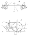
- the figure 1 shows a sectional view of a bearing cap 10 according to the state of the art, which comprises a semi-cylindrical shape 13 with an outer upper surface 11 and an inner lower surface 12 intended to be in contact with the crankshaft (not shown), said cylindrical shape comprises two diametrically opposed fixing pillars 20.
- Each fixing pillar is in the form of a column and rests on a substantially parallelepipedal heel 26.
- the bearing cap comprises a fixing pillar 20 disposed at each end of said cap.
- the bearing cap is made from cast iron essentially, in clusters or individually.
- Cluster molding consists of making all bearing caps in one piece, the number of bearing caps being equal to the number of cylinders of the engine plus one, for a given engine at one time. The part resulting from demolding then having several bearing caps juxtaposed along a transverse side is then cut to obtain the series of bearing caps.
- the bearing cap can also be derived from a cast iron individually.
- the mold includes a first sand mold for the outer cavity that provides the outer surface 11 of the cap and a second mold for the inner cavity that provides the inner surface of the cap that includes the lower surface 12 of the semi-cylindrical shape of the cap. bearing extended by the inner surface of the pillars and the substantially parallelepipedal heel.
- the bearing cap after demolding undergoes machining for the realization of the sidewalls 30, the outer upper surface 11 of the pillar, the lower surface 31 of the pillar intended to contact an element of a cylinder block (not shown) or foot bearing (not shown), through holes 15 for fastening screws (not shown) and the semi-cylindrical recess 12 adapted to surround a portion of the axis of the crankshaft.
- the pillar is of generally frustoconical shape to facilitate the demolding of the bearing cap.
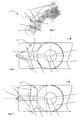
- FIGS. 3 to 5 show a bearing cap according to the invention comprising an upper surface 18 of substantially oblong abutment.
- the pillar is traversed by a circular opening 15 along the vertical axis Z for the passage of the fixing screw, the axis of the hole thus formed passes through the center O of a circular surface 16 of contact with the screw head. fixation and called support surface.
- the upper surface 18 can decompose into the bearing surface 16 and a second surface 17, the two end circles of the same radius and centers O and O 'intersect each other, the distance between the two centers being a few millimeters.
- the circular surface 17 is offset along the transverse axis Y, with respect to the bearing surface 16 towards the free end of the pillar. The additional mass generated by the second circular surface 17 contributes to improving the fatigue resistance of the bearing cap 10.
- two grooves 22, 23 are preferably obtained directly during molding on the outer lateral surface of the pillar. They are made in such a way that they do not interfere with a so-called support cylinder, whose base is equal to the bearing surface (16) over the entire height of the pillar. They are substantially vertical and symmetrical with respect to a transverse plane [YZ] passing through the axes of the fixing holes. Furthermore, the grooves are located outside an area 21 of a volume defined by the transverse plane and extending symmetrically in the X direction, said zone participating in the fatigue resistance of the bearing cap. This zone extends over a length e of a few millimeters on either side of said transverse plane.
- the profile of the grooves is defined by the profile of the notch formed in the pillar according to a top view of a horizontal section.
- the support cylinder and said volume form a security volume.
- the profile of the grooves symmetrical with respect to the transverse axis also makes the manufacturing process more reliable.
- the groove starts from the base of the pillar and extends at least over a portion of the height of the pillar. A surface is thus released at the base of said pillar on the heel.
- the groove may also continue along a substantially straight line to the upper surface 18 of the pillar following an inclination between the vertical Z and the line of inclination of the outer lateral surface of the pillar, and in such a way that its profile does not interfere with the security volume.
- the profile of the groove varies from the base of the pillar to a high end of the groove.
- the depth of said groove may for example vary from a low end to a high end of the groove.
- the Figures 5 and 6 have a profile of the grooves 22 substantially in an arc.
- the profile of the groove in a horizontal plane does not interfere with the projections on said horizontal plane with the security volume.
- the groove 22 is obtained raw from the molding by adding on the external sand footprint (not shown) a substantially semi-cylindrical boss on at least a portion of the height of the pillar.
- the figure 7 has a profile of the grooves 23 with square corner, the profile in a horizontal plane is between a longitudinal segment and a transverse segment, the two segments are such that their intersection does not interfere with the projections on said horizontal plane of the security volume .
- This groove profile corresponds to a significant reduction in the mass of the pillars 20 while improving the fatigue resistance of the bearing caps which comprise these pillars.
- the groove 23 is obtained raw from the molding by the addition on the external sand footprint (not shown) of a boss substantially square corner on at least a portion of the height of said pillar 20.
- Bearing caps must check fatigue resistance thresholds.
- the fatigue strength of the bearing caps depends on the profile of the connection zone 33 between the back of the bearing cap and the pillar of said cap and the profile of said pillar.
- Several documents including those from Engineering Techniques (BM 5 044-2 Method VDI) and the Conference of days of the foundry of France of September 19, 2005 report calculations of a fatigue safety factor (FSF) molded parts from fatigue limits and dispersions of the material that composes them.
- FSF fatigue safety factor
- the fatigue safety factor with a large number of cycles makes it possible to characterize the fatigue strength of the part for a given material. The higher the value, the better the fatigue life of the part.
- Bearing caps with pillars without grooves and pillars with grooves according to the invention are compared according to said factor.
- the invention allows optimization of the mass of the crankshaft bearing cap abutment.
- the pillar according to the invention is of column form with an oblong upper surface. Said column comprises grooves which contribute to the reduction of the abutment mass as well as to the improvement of the fatigue resistance of the bearing cap, in addition to complying with the rules described in the publication. FR2878588 .
- the invention is not limited to the embodiments presented above.
- Other groove profiles can be obtained directly by molding in order to reduce the mass of the pillars and the bearing cap while preserving or even improving the fatigue strength of said pillars.
- the groove profile may for example be trapezoidal.
Landscapes
- Engineering & Computer Science (AREA)
- General Engineering & Computer Science (AREA)
- Mechanical Engineering (AREA)
- Chemical & Material Sciences (AREA)
- Combustion & Propulsion (AREA)
- Shafts, Cranks, Connecting Bars, And Related Bearings (AREA)
- Cylinder Crankcases Of Internal Combustion Engines (AREA)
Description
- La présente invention concerne les chapeaux de paliers de vilebrequin et plus particulièrement la fixation de ces chapeaux de palier.
- L'invention concerne également les moteurs à combustion interne comprenant un vilebrequin dont l'axe est entouré par un palier et un chapeau de palier.
- Le chapeau de palier de vilebrequin est soumis à des contraintes importantes en particulier dans la zone se trouvant à proximité des piliers de fixation du chapeau de palier et au niveau desdits piliers eux-mêmes, contraintes pouvant engendrer des amorces de rupture et entrainer des défaillances de la pièce et en conséquence du moteur. Il est donc nécessaire de renforcer ledit chapeau et de renforcer sa résistance en fatigue. La pièce étant issue de moulage de fonte, ceci a pour conséquence généralement d'augmenter la masse du chapeau de palier et en partie celle des piliers, ce qui va à l'encontre des efforts de diminution de la masse de chaque composant pour réduire la consommation énergétique du moteur et/ ou du véhicule ou de privilégier des matériaux plus onéreux pour le moulage dudit chapeau de palier.
- La publication
FR2878588 B1 - La publication
US7384196 B2 divulgue un chapeau de palier de vilebrequin présentant une forme de demi-cylindre surmontée d'une portion d'arête cylindrique et comportant à chacune de ses extrémités un pilier de fixation de forme sensiblement cylindrique qui est rattaché au demi-cylindre par une bretelle, la section du demi-cylindre ainsi que celle de ladite bretelle étant optimisées du point de vue géométrique. Le document ne divulgue aucune règle de réalisation concernant le pilier de fixation. - La publication
US 2010/180853- A1 divulgue un chapeau de palier comportant deux piliers à chacune des extrémités dudit chapeau, chaque pilier comportant une surface supérieure sensiblement ovale et deux rainures verticales. - La publication
WO 2007/033139 - A2 présente un chapeau de palier comportant quatre piliers de fixation. - Un but de l'invention est une optimisation de la forme des piliers de chapeau de palier et l'invention a pour objet un chapeau de palier présentant une forme de demi-cylindre comportant des piliers de fixation diamétralement opposés avec un profil optimisé avec une réduction de la masse des piliers tout en améliorant la résistance en fatigue du chapeau de palier.
- Le chapeau de palier de vilebrequin selon l'invention est décrit dans la revendication 1.
- Le chapeau de palier de vilebrequin comporte une forme semi-cylindrique comportant à chacune de ses extrémités un pilier de fixation sous la forme d'une colonne sensiblement ovale légèrement évasée à la base qui comporte au moins deux rainures latérales sur au moins une portion de la hauteur du pilier. Lesdites rainures réduisent la masse des piliers de fixation et participent à l'amélioration de leur résistance en fatigue.
- Selon l'invention, les piliers de fixation comportent au moins deux rainures qui sont disposées hors d'un cylindre vertical d'appui dont la base est égale à la surface d'appui de la tête de vis et hors d'un volume défini par le plan transversal passant par les axes des trous de fixation et s'étendant symétriquement selon la direction X sur une longueur e. Les valeurs de tenue en fatigue sont avantageusement préservées ou améliorées.
- Les rainures sont issues depuis la base du pilier et se prolongent sur au moins une portion de la hauteur du pilier. Une surface à la base du pilier est ainsi avantageusement dégagée.
- Avantageusement, les rainures sont réalisées de façon symétrique par rapport à un plan transversal et vertical médian passant par l'axe de fixation. Le processus de fabrication est fiabilisé.
- Le profil des rainures varie depuis leur extrémité basse à leur extrémité haute. La profondeur qui est une dimension de la rainure peut varier de l'extrémité basse à l'extrémité haute de la rainure.
- Avantageusement, les rainures sont réalisées lors du moulage du chapeau de palier.
- D'autres aspects de l'invention vont être présentés dans la description suivante en regard des dessins annexés, donnée à titre d'exemple non limitatif, dans le seul but de bien comprendre l'invention et comment elle peut être réalisée.
-
- La
figure 1 est une vue de coupe selon la section AA de lafigure 3 du chapeau de palier de vilebrequin. - La
figure 2 est une vue en perspective d'un chapeau de palier de l'état de l'art. - La
figure 3 est une vue de dessus du chapeau de palier. - La
figure 4 est une vue de dessus d'une extrémité du chapeau de palier de l'état de l'art. - La
figure 5 est une vue en perspective d'un chapeau de palier selon l'invention. - Les
figures 6 et 7 sont des vues de dessus d'une extrémité du chapeau de palier selon deux modes de réalisation différents de l'invention. - Les descriptions qui suivent se réfèrent à l'axe longitudinal X confondu avec l'axe du vilebrequin, l'axe transversal Y et l'axe vertical Z.
- Les mêmes pièces apparaissant dans diverses figures gardent les mêmes références.
- La
figure 1 présente une vue de coupe d'un chapeau de palier 10 selon l'état de l'art, qui comprend une forme semi-cylindrique 13 avec une surface supérieure externe 11 et une surface inférieure interne 12 destinée à être au contact avec le vilebrequin (non présenté), ladite forme cylindrique comprend deux piliers de fixation 20 diamétralement opposés. Chaque pilier de fixation est en forme de colonne et repose sur un talon 26 sensiblement parallélépipédique. Selon lafigure 1 , le chapeau de palier comprend un pilier de fixation 20 disposé à chacune des extrémités dudit chapeau. - Le chapeau de palier est issu de moulage fonte essentiellement, en grappes ou en individuel. Le moulage en grappes consiste à réaliser tous les chapeaux de palier en une pièce, le nombre de chapeaux de paliers étant égal au nombre de cylindres du moteur plus un, pour un moteur donné en une fois. La pièce issue du démoulage présentant alors plusieurs chapeaux de paliers juxtaposés selon un côté transversal est ensuite tronçonnée pour obtenir la série de chapeaux de paliers. Le chapeau de palier peut également être issu d'un moulage fonte en individuel.
- Le moule comporte un premier moule sable pour l'empreinte externe qui réalise la surface externe 11 du chapeau et un deuxième moule pour l'empreinte intérieure qui réalise la surface interne du chapeau qui comprend la surface inférieure 12 de la forme semi-cylindrique du chapeau de palier prolongée par la surface intérieure des piliers et du talon sensiblement parallélépipédique. Le chapeau de palier après démoulage subit des usinages pour la réalisation des flancs 30, de la surface supérieure externe 11 du pilier, de la surface inférieure 31 du pilier destinée au contact avec un élément d'un carter cylindre (non représenté) ou de pied de palier (non représenté), des trous de passage 15 pour des vis de fixations (non représentés) et de l'évidement semi-cylindrique 12 adapté à entourer une partie de l'axe du vilebrequin.
- Le pilier est de forme générale tronconique pour faciliter le démoulage du chapeau de palier.
- Les
figures 3 à 5 montrent un chapeau de palier selon l'invention comprenant une surface supérieure 18 de pilier sensiblement oblongue. Le pilier est traversé par une ouverture circulaire 15 selon l'axe vertical Z pour le passage de la vis de fixation, l'axe du trou ainsi formé passe par le centre O d'une surface circulaire 16 de contact avec la tête de vis de fixation et dénommée surface d'appui. La surface supérieure 18 peut se décomposer en la surface d'appui 16 et une seconde surface 17 dont les deux cercles d'extrémité, de même rayon et de centres O et O', s'intersectent, la distance entre les deux centres étant de quelques millimètres. La surface circulaire 17 est décalée selon l'axe transversal Y, par rapport à la surface d'appui 16 vers l'extrémité libre du pilier. La masse supplémentaire engendrée par la seconde surface circulaire 17 participe à l'amélioration de la tenue en fatigue du chapeau de palier 10. - Selon l'invention, deux rainures 22,23 sont obtenues de manière préférentielle directement lors du moulage sur la surface latérale extérieure du pilier. Elles sont réalisées de telle façon qu'elles n'interfèrent pas avec un cylindre dit cylindre d'appui dont la base est égale à la surface d'appui (16) sur toute la hauteur du pilier. Elles sont sensiblement verticales et symétriques par rapport à un plan transversal [YZ] passant par les axes des trous de fixation. Par ailleurs, les rainures sont situées hors d'une zone 21 d'un volume défini par le plan transversal et s'étendant symétriquement selon la direction X, ladite zone participant à la résistance en fatigue du chapeau de palier. Cette zone s'étend sur une longueur e de quelques millimètres de part et d'autre dudit plan transversal. Le profil des rainures est défini par le profil de l'entaille formée dans le pilier selon une vue de dessus d'une coupe horizontale. Le cylindre d'appui et ledit volume forment un volume de sécurité. Le profil des rainures symétriques par rapport à l'axe transversal permet également de fiabiliser le processus de fabrication.
- La rainure débute depuis la base du pilier et se prolonge au moins sur une portion de la hauteur du pilier. Une surface est ainsi dégagée à la base dudit pilier sur le talon. La rainure peut également se poursuivre selon une ligne sensiblement droite jusqu'à la surface supérieure 18 du pilier en suivant une inclinaison comprise entre la verticale Z et la ligne d'inclinaison de la surface latérale extérieure du pilier, et de telle façon que son profil n'interfère pas avec le volume de sécurité.
- Le profil de la rainure varie depuis la base du pilier jusqu'à une extrémité haute de la rainure. La profondeur de ladite rainure peut par exemple varier d'une extrémité basse à une extrémité haute de la rainure.
- Les
figures 5 et 6 présentent un profil des rainures 22 sensiblement en arc de cercle. Le profil de la rainure selon un plan horizontal n'interfère pas sur les projections sur ledit plan horizontal avec le volume de sécurité. La rainure 22 est obtenue brute du moulage par l'ajout sur l'empreinte de sable externe (non représentée) d'un bossage sensiblement semi-cylindrique sur au moins une portion de la hauteur du pilier. - La
figure 7 présente un profil des rainures 23 à coin carré, le profil selon un plan horizontal est compris entre un segment longitudinal et un segment transversal, les deux segments sont tels que leur intersection n'interfère pas sur les projections sur ledit plan horizontal du volume de sécurité. Ce profil de rainure correspond à une réduction importante de la masse des piliers 20 tout en améliorant la résistance en fatigue des chapeaux de paliers qui comprennent ces piliers. La rainure 23 est obtenue brute du moulage par l'ajout sur l'empreinte de sable externe (non représentée) d'un bossage sensiblement à coin carré sur au moins une portion de la hauteur dudit pilier 20. - Les chapeaux de paliers doivent vérifier des seuils de tenue en fatigue. La tenue en fatigue des chapeaux de paliers dépend du profil de la zone de raccordement 33 entre le dos du chapeau de palier et le pilier dudit chapeau ainsi que du profil dudit pilier. Plusieurs documents dont ceux issus des Techniques de l'Ingénieur (BM 5 044-2 Méthode VDI) et de la conférence des journées de la fonderie de Strasbourg du 19 septembre 2005 font état de calculs d'un facteur de sécurité en fatigue (FSF) de pièces moulées à partir des limites de fatigue et de dispersions du matériau qui les compose. Le facteur de sécurité en fatigue à grand nombre de cycles permet de caractériser la tenue en fatigue de la pièce pour un matériau donné. Plus ladite valeur est importante, meilleure est la tenue en fatigue de la pièce. Des chapeaux de palier avec des piliers sans rainures et des piliers avec rainures selon l'invention sont comparés selon ledit facteur. Ce facteur marque une amélioration, passant d'une valeur de 1,25 pour un pilier sans rainures à 1,27 pour un pilier avec rainures selon les profils décrits précédemment. L'enlèvement de matière des piliers améliore donc également la tenue en fatigue du chapeau de palier. Ce résultat va à l'encontre de l'hypothèse selon laquelle une diminution de masse du pilier peut entrainer une dégradation des performances mécaniques du chapeau de palier, notamment de sa tenue en fatigue.
- L'invention permet une optimisation de la masse du pilier de chapeau de palier de vilebrequin. Le pilier selon l'invention est de forme de colonne avec une surface supérieure oblongue. Ladite colonne comporte des rainures qui participent à la réduction de la masse du pilier ainsi qu'à l'amélioration de la tenue en fatigue du chapeau de palier, en complément du respect des règles décrites dans la publication
FR2878588 - L'invention n'est pas limitée aux modes de réalisation présentés ci-dessus. D'autres profils de rainure peuvent être obtenus directement par moulage dans le but de réduire la masse des piliers et du chapeau de palier tout en préservant voire améliorant les tenues en fatigue desdits piliers. Le profil de rainure peut être par exemple trapézoïdal.
Claims (6)
- Chapeau de palier de vilebrequin (10) présentant la forme d'un demi-cylindre (13) d'axe X confondu avec l'axe du vilebrequin et comportant des piliers de fixation (20) diamétralement opposés, chaque pilier de forme de colonne, disposé à chacune des extrémités dudit chapeau de palier et reposant sur un talon (26) sensiblement parallélépipédique, comporte une surface supérieure (18) sensiblement ovale intégrant une surface d'appui (16) entourant un unique trou de passage (15) pour une vis de fixation ainsi qu'une surface d'appui de la tête de vis, ladite surface entourant le trou de passage (15), ledit pilier de fixation (20) à une extrémité du chapeau de palier comportant au moins deux rainures verticales sur la surface latérale extérieure du pilier, issues depuis la base du pilier sur le talon (26) et se prolongeant sur une portion de la hauteur du pilier, dégageant ainsi une surface à la base dudit pilier sur le talon, les rainures étant disposées hors d'un cylindre vertical d'appui dont la base est égale à la surface d'appui (16) et hors d'un volume défini par le plan transversal passant par les axes des trous de fixation et s'étendant symétriquement selon la direction X sur une longueur e.
- Chapeau de palier de vilebrequin selon la revendication 1, caractérisé en ce que le profil des rainures est symétrique par rapport à un axe transversal.
- Chapeau de palier de vilebrequin selon la revendication 2, caractérisé en ce que le profil des rainures varie depuis leur extrémité basse à leur extrémité haute.
- Chapeau de palier de vilebrequin selon la revendication 3, caractérisé en ce que le profil des rainures est en arc de cercle.
- Chapeau de palier de vilebrequin selon la revendication 4, caractérisé en ce que les rainures sont réalisées lors du moulage dudit chapeau de palier.
- Moteur à combustion interne comprenant un vilebrequin maintenu selon l'axe de rotation par des paliers et chapeaux de paliers selon l'une quelconque des revendications 1 à 5.
Applications Claiming Priority (2)
| Application Number | Priority Date | Filing Date | Title |
|---|---|---|---|
| FR1155708A FR2976988B1 (fr) | 2011-06-27 | 2011-06-27 | Chapeau de palier de villebrequin avec piliers optimises |
| PCT/FR2012/050513 WO2013001181A1 (fr) | 2011-06-27 | 2012-03-13 | Chapeau de palier de vilebrequin avec piliers optimises |
Publications (2)
| Publication Number | Publication Date |
|---|---|
| EP2724037A1 EP2724037A1 (fr) | 2014-04-30 |
| EP2724037B1 true EP2724037B1 (fr) | 2016-08-10 |
Family
ID=45937424
Family Applications (1)
| Application Number | Title | Priority Date | Filing Date |
|---|---|---|---|
| EP12713226.4A Active EP2724037B1 (fr) | 2011-06-27 | 2012-03-13 | Chapeau de palier de vilebrequin avec piliers optimises |
Country Status (8)
| Country | Link |
|---|---|
| US (1) | US9353787B2 (fr) |
| EP (1) | EP2724037B1 (fr) |
| JP (1) | JP6219274B2 (fr) |
| CN (1) | CN103649571B (fr) |
| ES (1) | ES2602034T3 (fr) |
| FR (1) | FR2976988B1 (fr) |
| RU (1) | RU2599106C2 (fr) |
| WO (1) | WO2013001181A1 (fr) |
Families Citing this family (4)
| Publication number | Priority date | Publication date | Assignee | Title |
|---|---|---|---|---|
| JP5884266B2 (ja) * | 2010-12-27 | 2016-03-15 | 日産自動車株式会社 | ベアリングキャップ及びラダーフレーム |
| AT519606B1 (de) * | 2017-02-02 | 2018-11-15 | Miba Sinter Austria Gmbh | Lagerdeckel |
| JP6874669B2 (ja) * | 2017-12-15 | 2021-05-19 | トヨタ自動車株式会社 | クランクキャップ組立体及び内燃機関 |
| US11041528B1 (en) | 2020-01-08 | 2021-06-22 | Cummins Inc. | Profiled main bearing caps |
Citations (1)
| Publication number | Priority date | Publication date | Assignee | Title |
|---|---|---|---|---|
| EP2615316A1 (fr) * | 2010-09-06 | 2013-07-17 | Nissan Motor Co., Ltd | Chapeau de palier métallique à base ferreuse, coulé dans un élément en alliage léger |
Family Cites Families (29)
| Publication number | Priority date | Publication date | Assignee | Title |
|---|---|---|---|---|
| US752349A (en) * | 1904-02-16 | Battery stem-guide | ||
| US118647A (en) * | 1871-08-29 | Improvement in journal-boxes | ||
| US1126888A (en) * | 1914-06-04 | 1915-02-02 | Aultman & Taylor Machinery Company | Connecting-rod. |
| US1410058A (en) * | 1919-11-28 | 1922-03-21 | Perry H Gentzel | Bearing clamp for engine shafts |
| US1764672A (en) * | 1926-12-07 | 1930-06-17 | Austin Herbert | Crank-shaft bearing |
| GB400544A (en) * | 1933-05-18 | 1933-10-26 | Atholl Blair | Improvements relating to cylindrical bearings, including connecting-rod big end bearings |
| US2407928A (en) * | 1941-10-30 | 1946-09-17 | Chrysler Corp | Fastening device |
| US2473096A (en) * | 1943-12-01 | 1949-06-14 | Hamill William Wilson | Connecting rod |
| US2997347A (en) * | 1959-05-21 | 1961-08-22 | Nat Lead Co | Bearing cap for internal combustion engines |
| US3893734A (en) * | 1974-04-01 | 1975-07-08 | Ford Motor Co | Thrust bearing |
| US4199202A (en) * | 1976-08-20 | 1980-04-22 | Toyota Jidosha Kogyo Kabushiki Kaisha | Bearing structure for a cam shaft in internal combustion engines |
| CH620023A5 (fr) * | 1977-06-17 | 1980-10-31 | Sulzer Ag | |
| DE3426208C1 (de) * | 1984-07-17 | 1986-03-06 | Dr.Ing.H.C. F. Porsche Ag, 7000 Stuttgart | Kurbelwellenlager fuer Brennkraftmaschinen |
| JPS61241444A (ja) * | 1985-04-19 | 1986-10-27 | Toyota Motor Corp | 一体型ベアリングキヤツプの製造方法 |
| US4993134A (en) * | 1988-05-17 | 1991-02-19 | Ford Motor Company | Making a fractured powder metal connecting rod |
| US5265700A (en) * | 1992-08-04 | 1993-11-30 | Briggs & Stratton Corporation | Lubrication for crankpin bearing of connecting rod |
| JPH10110721A (ja) * | 1996-10-02 | 1998-04-28 | Mitsubishi Motors Corp | 半割り滑り軸受 |
| US6276233B1 (en) * | 1999-12-21 | 2001-08-21 | Ford Global Tech., Inc. | Connecting rod and a method for making the same |
| MXPA02006615A (es) * | 2000-01-03 | 2004-09-10 | Zenith Sintered Products Inc | Agujeros siameses para pernos en componentes pulvimetalicos. |
| DE10152156C1 (de) * | 2001-10-25 | 2003-04-17 | Audi Ag | Kurbelwellenlagerung |
| DE60126629T2 (de) * | 2001-12-21 | 2007-11-22 | Ford Global Technologies, LLC, Dearborn | Hauptlagerdeckel für eine Brennkraftmaschine |
| FR2878588B1 (fr) * | 2004-11-26 | 2008-05-09 | Renault Sas | Chapeau de palier de vilebrequin |
| US7753592B2 (en) | 2005-09-13 | 2010-07-13 | Metaldyne Corporation | Bearing cap with weight reduction features |
| US20070081748A1 (en) * | 2005-10-06 | 2007-04-12 | Sitter Don H | Tab bearing |
| US7695823B2 (en) * | 2005-10-14 | 2010-04-13 | Gm Global Technology Operations, Inc. | Selectively reinforced powder metal components |
| US7322750B1 (en) * | 2005-11-18 | 2008-01-29 | Ronnie Besselman | Locking engine bearing splay cap |
| CN2883703Y (zh) * | 2005-12-24 | 2007-03-28 | 奇瑞汽车有限公司 | 发动机缸体轴承盖镶件 |
| US8327817B2 (en) * | 2009-01-19 | 2012-12-11 | Ford Global Technologies | Automotive engine bearing |
| JP5884266B2 (ja) * | 2010-12-27 | 2016-03-15 | 日産自動車株式会社 | ベアリングキャップ及びラダーフレーム |
-
2011
- 2011-06-27 FR FR1155708A patent/FR2976988B1/fr active Active
-
2012
- 2012-03-13 ES ES12713226.4T patent/ES2602034T3/es active Active
- 2012-03-13 JP JP2014517872A patent/JP6219274B2/ja active Active
- 2012-03-13 CN CN201280034572.0A patent/CN103649571B/zh active Active
- 2012-03-13 US US14/129,406 patent/US9353787B2/en not_active Expired - Fee Related
- 2012-03-13 RU RU2014102313/11A patent/RU2599106C2/ru active
- 2012-03-13 WO PCT/FR2012/050513 patent/WO2013001181A1/fr not_active Ceased
- 2012-03-13 EP EP12713226.4A patent/EP2724037B1/fr active Active
Patent Citations (1)
| Publication number | Priority date | Publication date | Assignee | Title |
|---|---|---|---|---|
| EP2615316A1 (fr) * | 2010-09-06 | 2013-07-17 | Nissan Motor Co., Ltd | Chapeau de palier métallique à base ferreuse, coulé dans un élément en alliage léger |
Also Published As
| Publication number | Publication date |
|---|---|
| EP2724037A1 (fr) | 2014-04-30 |
| JP6219274B2 (ja) | 2017-10-25 |
| RU2014102313A (ru) | 2015-08-10 |
| WO2013001181A1 (fr) | 2013-01-03 |
| CN103649571A (zh) | 2014-03-19 |
| RU2599106C2 (ru) | 2016-10-10 |
| US9353787B2 (en) | 2016-05-31 |
| US20140133791A1 (en) | 2014-05-15 |
| CN103649571B (zh) | 2017-03-22 |
| FR2976988A1 (fr) | 2012-12-28 |
| ES2602034T3 (es) | 2017-02-17 |
| JP2014521023A (ja) | 2014-08-25 |
| FR2976988B1 (fr) | 2014-04-11 |
Similar Documents
| Publication | Publication Date | Title |
|---|---|---|
| WO2013001181A1 (fr) | Chapeau de palier de vilebrequin avec piliers optimises | |
| EP1481756B1 (fr) | Procédé de fabrication d'une aube creuse pour turbomachine | |
| FR2538474A1 (fr) | Cage pour roulements a billes, en particulier pour roulements a billes a contact oblique | |
| FR3083150A1 (fr) | Moule de coulee en sable et procede de formation de moule de coulee en sable par impression 3d | |
| FR3090052A1 (fr) | Assemblage à pièces vissées auto-freinantes | |
| EP1855011B1 (fr) | Ensemble pour compresseur de moteur d'aéronef comprenant des aubes à attache marteau à pied incliné | |
| EP2206855A1 (fr) | Banche de moulage d'un voile en béton, ensemble de deux banches de ce type, et procédé d'assemblage des banches | |
| FR3064976A1 (fr) | Flotteur, notamment d'eolienne offshore. | |
| EP3154843B1 (fr) | Assemblage d'un élément de structure de véhicule automobile et d'un élément fonctionnel | |
| CA2912924C (fr) | Preforme d'aube de turbomachine | |
| FR2939117A1 (fr) | Element modulaire pesant, barre de lestage et contrepoids correspondants | |
| EP0598664B1 (fr) | Bielle constituée de deux parties assemblées l'une sur l'autre | |
| FR2855440A1 (fr) | Procede de fabrication d'une aube creuse pour turbomachine. | |
| EP3074651B1 (fr) | Cage de roulement a contact oblique et roulement à billes comportant une telle cage | |
| FR2970518A1 (fr) | Carter d'huile de moteur en deux parties avec interfaces de fixation incline | |
| JP4799047B2 (ja) | コンロッドおよびそれを備えた内燃機関ならびに自動車両 | |
| FR2970897A1 (fr) | Structure fibreuse formant une bride et une contre-bride | |
| EP2002098A1 (fr) | Culasse comprenant un noyau d'eau pourvu d'une partie de degazage et procede de fabrication d'une telle culasse | |
| FR3071188B1 (fr) | Cage bi-matiere a coussinets pour une rotule | |
| FR2917142A1 (fr) | Piece formant noix d'oldham. | |
| FR2474116A1 (fr) | Ecrou a un seul filet helicoidal interieur et son procede de fabrication | |
| FR2985752A1 (fr) | Sabot de fixation d'un montant de garde-corps | |
| CH696824A5 (fr) | Ancre d'échappement. | |
| FR3074240A1 (fr) | Carter comprenant un carter chapeau et au moins un insert formant un palier pour vilebrequin | |
| FR2833664A1 (fr) | Palier a roulement, notamment pour colonne de direction |
Legal Events
| Date | Code | Title | Description |
|---|---|---|---|
| PUAI | Public reference made under article 153(3) epc to a published international application that has entered the european phase |
Free format text: ORIGINAL CODE: 0009012 |
|
| 17P | Request for examination filed |
Effective date: 20131128 |
|
| AK | Designated contracting states |
Kind code of ref document: A1 Designated state(s): AL AT BE BG CH CY CZ DE DK EE ES FI FR GB GR HR HU IE IS IT LI LT LU LV MC MK MT NL NO PL PT RO RS SE SI SK SM TR |
|
| DAX | Request for extension of the european patent (deleted) | ||
| 17Q | First examination report despatched |
Effective date: 20150609 |
|
| GRAP | Despatch of communication of intention to grant a patent |
Free format text: ORIGINAL CODE: EPIDOSNIGR1 |
|
| INTG | Intention to grant announced |
Effective date: 20160324 |
|
| GRAS | Grant fee paid |
Free format text: ORIGINAL CODE: EPIDOSNIGR3 |
|
| GRAA | (expected) grant |
Free format text: ORIGINAL CODE: 0009210 |
|
| AK | Designated contracting states |
Kind code of ref document: B1 Designated state(s): AL AT BE BG CH CY CZ DE DK EE ES FI FR GB GR HR HU IE IS IT LI LT LU LV MC MK MT NL NO PL PT RO RS SE SI SK SM TR |
|
| REG | Reference to a national code |
Ref country code: GB Ref legal event code: FG4D Free format text: NOT ENGLISH |
|
| REG | Reference to a national code |
Ref country code: CH Ref legal event code: EP Ref country code: AT Ref legal event code: REF Ref document number: 819340 Country of ref document: AT Kind code of ref document: T Effective date: 20160815 |
|
| REG | Reference to a national code |
Ref country code: IE Ref legal event code: FG4D Free format text: LANGUAGE OF EP DOCUMENT: FRENCH |
|
| REG | Reference to a national code |
Ref country code: DE Ref legal event code: R096 Ref document number: 602012021460 Country of ref document: DE |
|
| REG | Reference to a national code |
Ref country code: LT Ref legal event code: MG4D |
|
| REG | Reference to a national code |
Ref country code: NL Ref legal event code: MP Effective date: 20160810 |
|
| REG | Reference to a national code |
Ref country code: AT Ref legal event code: MK05 Ref document number: 819340 Country of ref document: AT Kind code of ref document: T Effective date: 20160810 |
|
| PG25 | Lapsed in a contracting state [announced via postgrant information from national office to epo] |
Ref country code: NO Free format text: LAPSE BECAUSE OF FAILURE TO SUBMIT A TRANSLATION OF THE DESCRIPTION OR TO PAY THE FEE WITHIN THE PRESCRIBED TIME-LIMIT Effective date: 20161110 Ref country code: IS Free format text: LAPSE BECAUSE OF FAILURE TO SUBMIT A TRANSLATION OF THE DESCRIPTION OR TO PAY THE FEE WITHIN THE PRESCRIBED TIME-LIMIT Effective date: 20161210 Ref country code: NL Free format text: LAPSE BECAUSE OF FAILURE TO SUBMIT A TRANSLATION OF THE DESCRIPTION OR TO PAY THE FEE WITHIN THE PRESCRIBED TIME-LIMIT Effective date: 20160810 Ref country code: RS Free format text: LAPSE BECAUSE OF FAILURE TO SUBMIT A TRANSLATION OF THE DESCRIPTION OR TO PAY THE FEE WITHIN THE PRESCRIBED TIME-LIMIT Effective date: 20160810 Ref country code: LT Free format text: LAPSE BECAUSE OF FAILURE TO SUBMIT A TRANSLATION OF THE DESCRIPTION OR TO PAY THE FEE WITHIN THE PRESCRIBED TIME-LIMIT Effective date: 20160810 Ref country code: HR Free format text: LAPSE BECAUSE OF FAILURE TO SUBMIT A TRANSLATION OF THE DESCRIPTION OR TO PAY THE FEE WITHIN THE PRESCRIBED TIME-LIMIT Effective date: 20160810 Ref country code: IT Free format text: LAPSE BECAUSE OF FAILURE TO SUBMIT A TRANSLATION OF THE DESCRIPTION OR TO PAY THE FEE WITHIN THE PRESCRIBED TIME-LIMIT Effective date: 20160810 Ref country code: FI Free format text: LAPSE BECAUSE OF FAILURE TO SUBMIT A TRANSLATION OF THE DESCRIPTION OR TO PAY THE FEE WITHIN THE PRESCRIBED TIME-LIMIT Effective date: 20160810 |
|
| REG | Reference to a national code |
Ref country code: ES Ref legal event code: FG2A Ref document number: 2602034 Country of ref document: ES Kind code of ref document: T3 Effective date: 20170217 |
|
| PG25 | Lapsed in a contracting state [announced via postgrant information from national office to epo] |
Ref country code: AT Free format text: LAPSE BECAUSE OF FAILURE TO SUBMIT A TRANSLATION OF THE DESCRIPTION OR TO PAY THE FEE WITHIN THE PRESCRIBED TIME-LIMIT Effective date: 20160810 Ref country code: GR Free format text: LAPSE BECAUSE OF FAILURE TO SUBMIT A TRANSLATION OF THE DESCRIPTION OR TO PAY THE FEE WITHIN THE PRESCRIBED TIME-LIMIT Effective date: 20161111 Ref country code: PT Free format text: LAPSE BECAUSE OF FAILURE TO SUBMIT A TRANSLATION OF THE DESCRIPTION OR TO PAY THE FEE WITHIN THE PRESCRIBED TIME-LIMIT Effective date: 20161212 Ref country code: SE Free format text: LAPSE BECAUSE OF FAILURE TO SUBMIT A TRANSLATION OF THE DESCRIPTION OR TO PAY THE FEE WITHIN THE PRESCRIBED TIME-LIMIT Effective date: 20160810 Ref country code: PL Free format text: LAPSE BECAUSE OF FAILURE TO SUBMIT A TRANSLATION OF THE DESCRIPTION OR TO PAY THE FEE WITHIN THE PRESCRIBED TIME-LIMIT Effective date: 20160810 Ref country code: LV Free format text: LAPSE BECAUSE OF FAILURE TO SUBMIT A TRANSLATION OF THE DESCRIPTION OR TO PAY THE FEE WITHIN THE PRESCRIBED TIME-LIMIT Effective date: 20160810 |
|
| REG | Reference to a national code |
Ref country code: FR Ref legal event code: PLFP Year of fee payment: 6 |
|
| PG25 | Lapsed in a contracting state [announced via postgrant information from national office to epo] |
Ref country code: RO Free format text: LAPSE BECAUSE OF FAILURE TO SUBMIT A TRANSLATION OF THE DESCRIPTION OR TO PAY THE FEE WITHIN THE PRESCRIBED TIME-LIMIT Effective date: 20160810 Ref country code: EE Free format text: LAPSE BECAUSE OF FAILURE TO SUBMIT A TRANSLATION OF THE DESCRIPTION OR TO PAY THE FEE WITHIN THE PRESCRIBED TIME-LIMIT Effective date: 20160810 |
|
| REG | Reference to a national code |
Ref country code: DE Ref legal event code: R097 Ref document number: 602012021460 Country of ref document: DE |
|
| PG25 | Lapsed in a contracting state [announced via postgrant information from national office to epo] |
Ref country code: DK Free format text: LAPSE BECAUSE OF FAILURE TO SUBMIT A TRANSLATION OF THE DESCRIPTION OR TO PAY THE FEE WITHIN THE PRESCRIBED TIME-LIMIT Effective date: 20160810 Ref country code: SM Free format text: LAPSE BECAUSE OF FAILURE TO SUBMIT A TRANSLATION OF THE DESCRIPTION OR TO PAY THE FEE WITHIN THE PRESCRIBED TIME-LIMIT Effective date: 20160810 Ref country code: CZ Free format text: LAPSE BECAUSE OF FAILURE TO SUBMIT A TRANSLATION OF THE DESCRIPTION OR TO PAY THE FEE WITHIN THE PRESCRIBED TIME-LIMIT Effective date: 20160810 Ref country code: SK Free format text: LAPSE BECAUSE OF FAILURE TO SUBMIT A TRANSLATION OF THE DESCRIPTION OR TO PAY THE FEE WITHIN THE PRESCRIBED TIME-LIMIT Effective date: 20160810 Ref country code: BG Free format text: LAPSE BECAUSE OF FAILURE TO SUBMIT A TRANSLATION OF THE DESCRIPTION OR TO PAY THE FEE WITHIN THE PRESCRIBED TIME-LIMIT Effective date: 20161110 |
|
| PLBE | No opposition filed within time limit |
Free format text: ORIGINAL CODE: 0009261 |
|
| STAA | Information on the status of an ep patent application or granted ep patent |
Free format text: STATUS: NO OPPOSITION FILED WITHIN TIME LIMIT |
|
| 26N | No opposition filed |
Effective date: 20170511 |
|
| PG25 | Lapsed in a contracting state [announced via postgrant information from national office to epo] |
Ref country code: SI Free format text: LAPSE BECAUSE OF FAILURE TO SUBMIT A TRANSLATION OF THE DESCRIPTION OR TO PAY THE FEE WITHIN THE PRESCRIBED TIME-LIMIT Effective date: 20160810 |
|
| REG | Reference to a national code |
Ref country code: CH Ref legal event code: PL |
|
| PG25 | Lapsed in a contracting state [announced via postgrant information from national office to epo] |
Ref country code: MC Free format text: LAPSE BECAUSE OF FAILURE TO SUBMIT A TRANSLATION OF THE DESCRIPTION OR TO PAY THE FEE WITHIN THE PRESCRIBED TIME-LIMIT Effective date: 20160810 |
|
| REG | Reference to a national code |
Ref country code: IE Ref legal event code: MM4A |
|
| PG25 | Lapsed in a contracting state [announced via postgrant information from national office to epo] |
Ref country code: LU Free format text: LAPSE BECAUSE OF NON-PAYMENT OF DUE FEES Effective date: 20170313 |
|
| PG25 | Lapsed in a contracting state [announced via postgrant information from national office to epo] |
Ref country code: IE Free format text: LAPSE BECAUSE OF NON-PAYMENT OF DUE FEES Effective date: 20170313 Ref country code: LI Free format text: LAPSE BECAUSE OF NON-PAYMENT OF DUE FEES Effective date: 20170331 Ref country code: CH Free format text: LAPSE BECAUSE OF NON-PAYMENT OF DUE FEES Effective date: 20170331 |
|
| REG | Reference to a national code |
Ref country code: BE Ref legal event code: MM Effective date: 20170331 |
|
| REG | Reference to a national code |
Ref country code: FR Ref legal event code: PLFP Year of fee payment: 7 |
|
| PG25 | Lapsed in a contracting state [announced via postgrant information from national office to epo] |
Ref country code: BE Free format text: LAPSE BECAUSE OF NON-PAYMENT OF DUE FEES Effective date: 20170331 |
|
| PG25 | Lapsed in a contracting state [announced via postgrant information from national office to epo] |
Ref country code: MT Free format text: LAPSE BECAUSE OF FAILURE TO SUBMIT A TRANSLATION OF THE DESCRIPTION OR TO PAY THE FEE WITHIN THE PRESCRIBED TIME-LIMIT Effective date: 20160810 |
|
| PG25 | Lapsed in a contracting state [announced via postgrant information from national office to epo] |
Ref country code: AL Free format text: LAPSE BECAUSE OF FAILURE TO SUBMIT A TRANSLATION OF THE DESCRIPTION OR TO PAY THE FEE WITHIN THE PRESCRIBED TIME-LIMIT Effective date: 20160810 |
|
| PG25 | Lapsed in a contracting state [announced via postgrant information from national office to epo] |
Ref country code: HU Free format text: LAPSE BECAUSE OF FAILURE TO SUBMIT A TRANSLATION OF THE DESCRIPTION OR TO PAY THE FEE WITHIN THE PRESCRIBED TIME-LIMIT; INVALID AB INITIO Effective date: 20120313 |
|
| PG25 | Lapsed in a contracting state [announced via postgrant information from national office to epo] |
Ref country code: CY Free format text: LAPSE BECAUSE OF NON-PAYMENT OF DUE FEES Effective date: 20160810 |
|
| PG25 | Lapsed in a contracting state [announced via postgrant information from national office to epo] |
Ref country code: MK Free format text: LAPSE BECAUSE OF FAILURE TO SUBMIT A TRANSLATION OF THE DESCRIPTION OR TO PAY THE FEE WITHIN THE PRESCRIBED TIME-LIMIT Effective date: 20160810 |
|
| PG25 | Lapsed in a contracting state [announced via postgrant information from national office to epo] |
Ref country code: TR Free format text: LAPSE BECAUSE OF FAILURE TO SUBMIT A TRANSLATION OF THE DESCRIPTION OR TO PAY THE FEE WITHIN THE PRESCRIBED TIME-LIMIT Effective date: 20160810 |
|
| P01 | Opt-out of the competence of the unified patent court (upc) registered |
Effective date: 20230608 |
|
| REG | Reference to a national code |
Ref country code: GB Ref legal event code: 732E Free format text: REGISTERED BETWEEN 20231228 AND 20240103 |
|
| REG | Reference to a national code |
Ref country code: DE Ref legal event code: R081 Ref document number: 602012021460 Country of ref document: DE Owner name: NEW H POWERTRAIN HOLDING, S.L.U., ES Free format text: FORMER OWNER: RENAULT S.A.S., BOULOGNE-BILLANCOURT, FR |
|
| REG | Reference to a national code |
Ref country code: ES Ref legal event code: PC2A Owner name: NEW H POWERTRAIN HOLDING, S.L.U. Effective date: 20240805 |
|
| PGFP | Annual fee paid to national office [announced via postgrant information from national office to epo] |
Ref country code: ES Payment date: 20250428 Year of fee payment: 14 |
|
| PGFP | Annual fee paid to national office [announced via postgrant information from national office to epo] |
Ref country code: GB Payment date: 20260324 Year of fee payment: 15 |
|
| PGFP | Annual fee paid to national office [announced via postgrant information from national office to epo] |
Ref country code: DE Payment date: 20260319 Year of fee payment: 15 |
|
| PGFP | Annual fee paid to national office [announced via postgrant information from national office to epo] |
Ref country code: FR Payment date: 20260320 Year of fee payment: 15 |