EP2720658B1 - Patient interface defogger - Google Patents
Patient interface defogger Download PDFInfo
- Publication number
- EP2720658B1 EP2720658B1 EP12745970.9A EP12745970A EP2720658B1 EP 2720658 B1 EP2720658 B1 EP 2720658B1 EP 12745970 A EP12745970 A EP 12745970A EP 2720658 B1 EP2720658 B1 EP 2720658B1
- Authority
- EP
- European Patent Office
- Prior art keywords
- vacuum
- decondenser
- air
- eye
- pressure
- Prior art date
- Legal status (The legal status is an assumption and is not a legal conclusion. Google has not performed a legal analysis and makes no representation as to the accuracy of the status listed.)
- Active
Links
- 238000003032 molecular docking Methods 0.000 claims description 62
- 238000009833 condensation Methods 0.000 claims description 21
- 230000005494 condensation Effects 0.000 claims description 21
- 238000010168 coupling process Methods 0.000 claims description 13
- 230000008878 coupling Effects 0.000 claims description 12
- 238000005859 coupling reaction Methods 0.000 claims description 12
- 238000004891 communication Methods 0.000 claims description 9
- 239000012530 fluid Substances 0.000 claims description 9
- 238000012546 transfer Methods 0.000 claims description 2
- 239000003570 air Substances 0.000 description 55
- 238000000034 method Methods 0.000 description 16
- 230000003287 optical effect Effects 0.000 description 15
- 239000007789 gas Substances 0.000 description 12
- 238000003384 imaging method Methods 0.000 description 8
- 230000008569 process Effects 0.000 description 6
- XLYOFNOQVPJJNP-UHFFFAOYSA-N water Substances O XLYOFNOQVPJJNP-UHFFFAOYSA-N 0.000 description 6
- 238000010438 heat treatment Methods 0.000 description 5
- 230000006870 function Effects 0.000 description 4
- 230000036760 body temperature Effects 0.000 description 3
- 230000033001 locomotion Effects 0.000 description 3
- 230000001105 regulatory effect Effects 0.000 description 3
- IJGRMHOSHXDMSA-UHFFFAOYSA-N Atomic nitrogen Chemical compound N#N IJGRMHOSHXDMSA-UHFFFAOYSA-N 0.000 description 2
- 239000012080 ambient air Substances 0.000 description 2
- 210000004087 cornea Anatomy 0.000 description 2
- 238000013461 design Methods 0.000 description 2
- 238000001704 evaporation Methods 0.000 description 2
- 238000004519 manufacturing process Methods 0.000 description 2
- 238000005086 pumping Methods 0.000 description 2
- 208000028006 Corneal injury Diseases 0.000 description 1
- 208000012661 Dyskinesia Diseases 0.000 description 1
- 208000015592 Involuntary movements Diseases 0.000 description 1
- 230000009471 action Effects 0.000 description 1
- 230000008901 benefit Effects 0.000 description 1
- 230000008859 change Effects 0.000 description 1
- 239000012141 concentrate Substances 0.000 description 1
- 239000000470 constituent Substances 0.000 description 1
- 230000001276 controlling effect Effects 0.000 description 1
- 238000012937 correction Methods 0.000 description 1
- 230000001419 dependent effect Effects 0.000 description 1
- 238000001035 drying Methods 0.000 description 1
- 230000000694 effects Effects 0.000 description 1
- 239000013013 elastic material Substances 0.000 description 1
- 238000011065 in-situ storage Methods 0.000 description 1
- 239000011261 inert gas Substances 0.000 description 1
- 230000007794 irritation Effects 0.000 description 1
- 230000007246 mechanism Effects 0.000 description 1
- 238000001000 micrograph Methods 0.000 description 1
- 238000012986 modification Methods 0.000 description 1
- 230000004048 modification Effects 0.000 description 1
- 230000017311 musculoskeletal movement, spinal reflex action Effects 0.000 description 1
- 229910052757 nitrogen Inorganic materials 0.000 description 1
- 230000037361 pathway Effects 0.000 description 1
- 238000003825 pressing Methods 0.000 description 1
- 238000012545 processing Methods 0.000 description 1
- 230000004044 response Effects 0.000 description 1
- 238000001356 surgical procedure Methods 0.000 description 1
- 230000008685 targeting Effects 0.000 description 1
Images


Classifications
-
- A—HUMAN NECESSITIES
- A61—MEDICAL OR VETERINARY SCIENCE; HYGIENE
- A61F—FILTERS IMPLANTABLE INTO BLOOD VESSELS; PROSTHESES; DEVICES PROVIDING PATENCY TO, OR PREVENTING COLLAPSING OF, TUBULAR STRUCTURES OF THE BODY, e.g. STENTS; ORTHOPAEDIC, NURSING OR CONTRACEPTIVE DEVICES; FOMENTATION; TREATMENT OR PROTECTION OF EYES OR EARS; BANDAGES, DRESSINGS OR ABSORBENT PADS; FIRST-AID KITS
- A61F9/00—Methods or devices for treatment of the eyes; Devices for putting in contact-lenses; Devices to correct squinting; Apparatus to guide the blind; Protective devices for the eyes, carried on the body or in the hand
- A61F9/007—Methods or devices for eye surgery
- A61F9/008—Methods or devices for eye surgery using laser
- A61F9/009—Auxiliary devices making contact with the eyeball and coupling in laser light, e.g. goniolenses
-
- A—HUMAN NECESSITIES
- A61—MEDICAL OR VETERINARY SCIENCE; HYGIENE
- A61F—FILTERS IMPLANTABLE INTO BLOOD VESSELS; PROSTHESES; DEVICES PROVIDING PATENCY TO, OR PREVENTING COLLAPSING OF, TUBULAR STRUCTURES OF THE BODY, e.g. STENTS; ORTHOPAEDIC, NURSING OR CONTRACEPTIVE DEVICES; FOMENTATION; TREATMENT OR PROTECTION OF EYES OR EARS; BANDAGES, DRESSINGS OR ABSORBENT PADS; FIRST-AID KITS
- A61F9/00—Methods or devices for treatment of the eyes; Devices for putting in contact-lenses; Devices to correct squinting; Apparatus to guide the blind; Protective devices for the eyes, carried on the body or in the hand
- A61F9/007—Methods or devices for eye surgery
- A61F9/008—Methods or devices for eye surgery using laser
- A61F9/00825—Methods or devices for eye surgery using laser for photodisruption
-
- A—HUMAN NECESSITIES
- A61—MEDICAL OR VETERINARY SCIENCE; HYGIENE
- A61F—FILTERS IMPLANTABLE INTO BLOOD VESSELS; PROSTHESES; DEVICES PROVIDING PATENCY TO, OR PREVENTING COLLAPSING OF, TUBULAR STRUCTURES OF THE BODY, e.g. STENTS; ORTHOPAEDIC, NURSING OR CONTRACEPTIVE DEVICES; FOMENTATION; TREATMENT OR PROTECTION OF EYES OR EARS; BANDAGES, DRESSINGS OR ABSORBENT PADS; FIRST-AID KITS
- A61F9/00—Methods or devices for treatment of the eyes; Devices for putting in contact-lenses; Devices to correct squinting; Apparatus to guide the blind; Protective devices for the eyes, carried on the body or in the hand
- A61F9/007—Methods or devices for eye surgery
- A61F9/008—Methods or devices for eye surgery using laser
- A61F2009/00844—Feedback systems
- A61F2009/00846—Eyetracking
-
- A—HUMAN NECESSITIES
- A61—MEDICAL OR VETERINARY SCIENCE; HYGIENE
- A61F—FILTERS IMPLANTABLE INTO BLOOD VESSELS; PROSTHESES; DEVICES PROVIDING PATENCY TO, OR PREVENTING COLLAPSING OF, TUBULAR STRUCTURES OF THE BODY, e.g. STENTS; ORTHOPAEDIC, NURSING OR CONTRACEPTIVE DEVICES; FOMENTATION; TREATMENT OR PROTECTION OF EYES OR EARS; BANDAGES, DRESSINGS OR ABSORBENT PADS; FIRST-AID KITS
- A61F9/00—Methods or devices for treatment of the eyes; Devices for putting in contact-lenses; Devices to correct squinting; Apparatus to guide the blind; Protective devices for the eyes, carried on the body or in the hand
- A61F9/007—Methods or devices for eye surgery
- A61F9/008—Methods or devices for eye surgery using laser
- A61F2009/00844—Feedback systems
- A61F2009/00851—Optical coherence topography [OCT]
Definitions
- This patent document relates to patient interfaces for ophthalmic procedures.
- this patent document relates to defogging systems for patient interfaces of ophthalmic surgical laser systems.
- a central docking aligns an optical axis of the objective of the laser system and an optical axis of the eye. Since the surgical laser beam is typically directed and controlled relative to the optical axis of the objective, aligning the optical axis of the eye with the optical axis of the objective by a central docking can enable controlling and directing the laser beam in the eye with high precision.
- laser surgical systems often assist the surgeon by including an advanced imaging system.
- This advanced imaging system can include a stereo microscope, a video monitor and sometimes an Optical Coherence Tomographic (OCT) device.
- OCT Optical Coherence Tomographic
- integrating these advanced imaging systems into the surgical systems that also use a patient interface can introduce challenges for the system design.
- the present invention provides an ophthalmic docking system in accordance with claims which follow.
- One of the design challenges is that during the alignment process the patient interface is kept a few millimeters above the eye for an extended period. During this time the surgeon can operate the video or OCT imaging systems, analyze the pictures and maneuver and adjust the objective by operating a gantry of the laser surgical system, for example. During all this time, however, water evaporates from the surface of the eye, creating a water vapor-rich atmosphere between the eye and the contact lens. In most systems, the temperature of the contact lens is typically lower than that of the body and the eye. Because of this temperature difference, the water can condense from the vapor onto the contact lens. This condensation can degrade the visibility through the patient interface, introducing blurriness to the video image and noise into the OCT image. Both these effects can disadvantageously reduce the precision of the alignment and docking process.
- an ophthalmic docking system comprises a patient interface, having a proximal portion configured to be attached to an ophthalmic system, a distal portion configured to be attached to an eye, including a contact lens and an interface attachment system, and a decondenser, coupled to the patient interface configured to reduce a vapor condensation on the contact lens.
- An exemplary method of ophthalmic docking includes providing a patient interface having a contact lens and coupled to a decondenser, generating a decondensing gas flow by the decondenser towards the contact lens prior to a docking of the patient interface to an eye, and docking the patient interface to the eye.
- An ophthalmic interface system may include a patient interface, attachable to an ophthalmic laser system, the patient interface including a contact lens to be docked to an eye, and a desiccating system, configured to direct a desiccating gas flow towards the contact lens.
- Implementations and embodiments in this patent document provide an ophthalmic docking system that can reduce or eliminate the condensation on the contact lens of the patient interface.
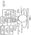
- FIG. 1 illustrates an ophthalmic surgical laser system 100.
- the laser system 100 can include a surgical laser 110 that can generate and couple a surgical laser beam into an optic 120 at a beam splitter BS1.
- the surgical laser 110 can be capable of generating a pulsed laser beam with a femtosecond pulse length.
- the optic 120 can redirect and deliver the pulsed laser beam into a docking eye 1d of a patient 10 through an objective 122 and a patient interface, or PI, 210 that is docked onto the docking eye 1d.
- the laser system 100 can also include an imaging system 130.
- the imaging system 130 can provide one or more images for an ophthalmic surgeon to increase the precision of the docking of the PI 210 and in general of the ophthalmic procedures carried out with the laser system 100.
- the images can include a stereoscopic microscope image, a video-image, and an Optical Coherence Tomographic, or OCT image.
- the image can be analyzed by an image processor 132.
- the generated image can be displayed on a guidance system 140.
- One of the functions of the guidance system 140 can be to guide the surgeon to align a center of the eye and a center or axis of the optic 120 for optimizing the docking of the PI 210.
- the guidance system 140 can include a video-monitor to display the video-image created by the imaging system 130.
- the guidance system 140 can include an OCT display to display the OCT image created by the imaging system 130.
- the guidance system 140 can include a guidance display to guide the surgeon based on the result of the processing of the image by the image processor 132.
- the guidance display of the guidance system 140 can include a target pattern or a crosshair pattern overlaid on the video image of the eye to indicate a position of an optical center or axis of the optic 120 relative to a center of the eye.
- the guidance system 140 can display one or more arrows to suggest the surgeon a corrective action to align the optic 120 and the eye 1d.
- the guidance system 140 can display aligning icons determined from an analysis of the OCT image by the image processor 132.
- the correction of the alignment can be initiated either by the surgeon or by a processor of the surgical laser system 100, in response to the above described types of guidance information generated by the guidance system 140.
- some embodiments of the laser system 100 can include a gantry 152 and a gantry controller 154 to move the objective 122 laterally and align it with a center of the eye as part of the docking procedure.
- a gantry 152 can compensate a lateral or transverse misalignment of the eye 1d and the optic 120, but not necessarily a rotational misalignment.
- a rotational or angular misalignment of the eye 1d and the optical axis of the optic 120 can be compensated by a fixation light source 156 that projects a fixation light 158 into a control eye 1c, for example.
- the patient 10 can be instructed to follow the movement of the fixation light 158.
- the surgeon adjusts the fixation light 158, he or she can track the movement of the eye's video image relative to the optical axis of the optic 120 on the guidance display 140 and continue to adjust the fixation light 158 until the docking eye 1d is aligned with the optical axis of the optic 120 to the desired degree.
- the patient interface 210 may be only millimeters above the docking eye 1d.
- the wet surface of the docking eye 1d is continuously evaporating water vapor that can condense on a contact lens of the patient interface 210, since the temperature of the contact lens is typically lower than the body temperature and the vapor-rich air is getting trapped between the eye and the contact lens.
- This water condensate can fog up the optical pathway, making the video image blurry and the OCT image noisy. Therefore, the water condensation can undermine and endanger the precision and efficiency of the above alignment and docking process, threatening the success of the overall surgical procedure.
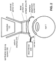
- FIG. 2 illustrates parts of the claimed ophthalmic docking system 200 that can offer solutions for the condensation problem.
- the docking system 200 can include the patient interface, or PI 210.
- the patient interface 210 can have a proximal portion or attachment cone 212, to be attached to an ophthalmic system, such as the surgical laser system 100 and in particular to its objective 122.
- the patient interface 210 can also include a distal portion 214 to be attached to an eye 1, such as the docking eye 1d.
- the proximal portion 212 and the distal portion 214 can be integral parts of a single patient interface 210, which can be made of a single plastic mold or an elastic material, for example.
- the portions 212 and 214 can be manufactured separately and then assembled during the manufacturing process.
- portions 212 and 214 can be separate elements that are affixed together by the surgeon during the docking process.
- the distal portion 214 can include a contact lens or applanation lens 216 that is pressed against a cornea 2 of the eye 1 during docking to establish a well-defined and controlled optical interface between the optic 120 of the laser system 100 and the docking eye 1d or 1 for short.
- the well defined optical interface defined by the contact lens 216 having e.g. a known radius of curvature, allows the high precision targeting of the surgical laser beam onto or into surgical targets, such as a lens 3 of the eye.
- the distal portion 214 can also include an interface attachment system 218 as described below in detail.
- the ophthalmic docking system 200 can include a decondenser 220.
- Some examples of the decondenser 220 can be called a defogger, a desiccator or a dehumidifier as well.
- the decondenser 220 can be coupled to the patient interface 210.
- One of the functions of the decondenser 220 can be to reduce a vapor condensation on the contact lens 216. This functionality can be achieved in different manners.
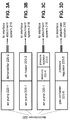
- FIG. 3A illustrates that some examples of the decondenser 220 deliver a suitably prepared airflow to the contact lens 216 to reduce the vapor condensation on the contact lens 216.
- Such decondensers 220 may include an air pump 220-1 that can pump air towards the interface attachment system 218. In its simplest realization, pumping ambient air by the air-pump 220-1 to the contact lens 216 can blow away the vapor-rich air between the contact lens 216 and the eye 1 and replace it with ambient air that does not contain excess vapor, thereby reducing the condensation on the contact lens 216.
- decondensers 220 can include a dehumidifier or desiccator 220-2 that can reduce a vapor content of an airflow directed towards the interface attachment system 218 by the air pump 220-1. Once a reduced-vapor content air replaces the high-vapor content air evaporating from the eye 1, the fogging of the contact lens 216 is reduced or possibly eliminated.
- embodiments can include their constituent elements in different order.
- the air pump 220-1 can pump the air into the dehumidifier 220-2, whereas in other systems the dehumidifier 220-2 can provide low-humidity air for the air pump 220-1.
- FIG. 3B illustrates that in some examples, the decondenser 220 can include an air-heater 220-3 that can increase a temperature of an airflow directed towards the interface attachment system 218.
- Heated air can defog the contact lens 216 by multiple mechanisms.
- Higher temperature air has a higher dew-point than ambient temperature air and therefore can accommodate more vapor without forcing its condensation into a dew or condensation on the contact lens 216.
- replacing the vapor-rich, ambient temperature air with higher temperature air reduces the condensation on the contact lens 216.
- the heated air heats the contact lens 216 as well. For similar physical reasons as above, the warmer the contact lens 216, the lesser the degree of vapor condensation.
- the air-heater 220-3 can include a temperature controller that controls the temperature of the heated air to approximately body temperature or slightly higher. A much higher temperature can cause irritation or burning of the corneal tissue, whereas a lower temperature may not be able to prevent the condensation effectively.
- FIG. 3C illustrates that some decondensers 220 can include a reservoir 220-4 that can store high-pressure air pumped by the air pump 220-1 at a pressure higher than an ambient pressure.
- the reservoir 220-4 can be capable of forwarding the higher-than-ambient pressure, or high-pressure air towards the interface attachment system 218. Both the high pressure and the speed of the air reduce the condensation on the contact lens 216.
- the term high-pressure air can refer to air with a pressure higher than an ambient pressure. The pressure of the high-pressure air can be only moderately or fractionally higher than the ambient pressure.
- a utility of the reservoir 220-4 is that a docking system 200 with a reservoir 220-4 can make use of a smaller air pump 220-1 that pumps up the reservoir 220-4 over an extended period to a pressure higher than what the air pump 220-1 could achieve in real time.
- the reservoir 220-4 can advantageously "step-up”, “up-convert”, or “buffer” the pressure of the airflow.
- the pressure of the high-pressure air can be regulated by a pressure regulator 220-5.
- This pressure regulator 220-5 can be useful in systems where the air-pump 220-1 delivers the air with a varying pressure.
- the pressure can vary for different reasons. Most pumps operate by repeating a mechanical cycle with a high repetition rate. The pressure of the pumped air can oscillate within each cycle.
- the operating voltage of the air pump 220-1 can drift or change when other sub-systems of the surgical laser system 100 start drawing power from the on-board power supply, or if the external voltage of the system 100 experiences a fluctuation.
- the decondenser 220 can include the pressure regulator 220-5 that can forward the high-pressure air towards the interface attachment system 218 with a pressure fluctuation smaller than a pressure fluctuation of the high-pressure air pumped by the air pump 220-1 to the reservoir 220-4.
- the pressure regulator 220-5 can minimize or even eliminate the pressure fluctuations of the pumped air, received from the air pump 220-1.
- FIG. 3D illustrates that in some examples, the decondenser 220 can include a gas container 220-6 that can store a high-pressure gas at a pressure higher than an ambient pressure, and can forward this high-pressure gas towards the interface attachment system 218.
- the stored gas need not be air: it can be, for example, an inert gas or nitrogen, among others.
- Such systems can also include the pressure regulator 220-5 to regulate the pressure of the gas, as the gas container 220-6 may release the gas with a pressure that changes over time.
- FIG. 3E illustrates that the elements of FIGS. 3A-D can be combined in different ways and in different sequences.
- the decondenser or desiccator 220 of FIG. 3E can include the air-pump 220-1, pumping air to the dehumidifier 220-2, which can output a low-humidity airflow to the air-heater 220-3.
- the air-heater 220-3 can increase the temperature of this low-humidity airflow and guide it into the reservoir 220-4 that can buffer the airflow thus increasing the pressure of the stored or buffered air.
- a valve of the reservoir 220-4 or a connecting decondenser-hose 222 can be opened and the high pressure/low humidity/high temperature air can be directed from the reservoir 220-4 to the contact lens 216, greatly reducing and possibly eliminating the condensation on it.
- Numerous other combinations of the elements 220-1 to 220-6 can be used as well.
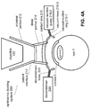
- FIG. 4A illustrates that the interface attachment system 218 includes a vacuum-suction ring 218-1 that preferably partially defines a toroidal volume when attached to the eye 1.
- the interface attachment system 218 also includes a vacuum-suction pump 218-2 that can generate vacuum suction, and a vacuum-hose 218-3 that can couple the vacuum-suction pump 218-2 to the vacuum-suction ring 218-1 to transfer the vacuum suction generated by the vacuum-suction pump 218-2 to the toroidal volume of the vacuum-suction ring 218-1 to create a seal between the vacuum-suction ring 218-1 and the eye 1, thereby attaching the patient interface 210 to the eye 1.
- the interface attachment system 218 can include a vacuum skirt, multiple vacuum-suction rings, or a vacuum-skirt with multiple flanges or ridges.
- the vacuum-suction pump 218-2 applies a vacuum suction and this suction gets transferred by the vacuum-hose 218-3, these embodiments also get sealed to the eye 1 to provide an attachment or grip of the patient interface 210 to the eye 1.
- the decondenser 220 can be coupled to the vacuum-suction ring 218-1 via a decondenser-hose, or decondenser-tubing 222.
- This decondenser-hose 222 can provide fluid communication between the decondenser 220 and the vacuum-suction ring 218-1.
- a coordinated regulation of the system can be used as the decondenser 220 may blow air into a chamber, defined by the contact lens 216 and the vacuum suction ring 218-1, whereas the vacuum-suction pump 218-2 removes air from the same chamber to create an attachment seal by vacuum suction. Because of these functions are opposing, a coordination of these two functions may be necessary to avoid the decondenser 220 working against the vacuum-suction pump 218-2.
- the decondenser 220 can be operated whereas the vacuum-suction pump 218-2 may not be engaged.
- the decondenser 220 may stop and the vacuum-suction pump 218-2 may start to operate to create the attachment seal between the contact lens 216 and the eye 1.
- the surgical space around the patient interface 210 can be quite crowded.
- having two separate hoses or tubings 218-3 and 222 attached to the vacuum-suction ring 218-1 may pose challenges for managing the tight surgical space and access.
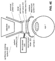
- FIG. 4B illustrates the invention where the interface attachment system 218 and the decondenser system 220 are regulated or coordinated efficiently, as well as also reducing the clutter of the tight surgical space.
- the interface attachment system 218 includes the vacuum-suction ring 218-1 that has a fluid coupling to a valve 230.
- the valve 230 is coupled to the vacuum-suction pump 218-2 by the vacuum-hose 218-3 and to the desiccator 220 by the decondenser-hose 222.
- the valve 230 is capable of switching between a fluid communication channel connecting the vacuum-pump 218-2 and the vacuum-suction ring 218-1 and a fluid communication channel connecting the decondenser 220 and the vacuum-suction ring 218-1.
- the valve 230 can coordinate an operation of the vacuum-pump 218-2 with an operation of the decondenser 220 by granting fluid communication for only one of them to the vacuum-suction ring 218-1, thereby preventing that these two systems work against each other.
- the valve 230 may direct the heated or pressurized or dehumidified airflow from the decondenser 220 onto the contact lens 216 to keep the contact lens 216 condensation free, thus securing the high precision of the alignment.
- the valve 230 can switch fluid communication channels, disconnecting the decondenser 220 and connecting the vacuum-suction pump 218-2 to the vacuum-suction ring 218-1 to provide the vacuum-suction to complete the attachment of the patient interface 210 to the eye.
- the invention with the valve 230 (i) can coordinate the operation of the decondenser 220 and the vacuum-suction pump 218-2 efficiently, (ii) can ensure that the contact lens 216 is kept condensation free up to the moment of the docking, and (iii) do not introduce additional space demands to the already crowded surgical space around the eye, such as the need for a second access port.
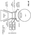
- FIG. 4C illustrates an embodiment of the decondenser 220 that integrates the decondensing and vacuum-suction functionalities.
- the decondenser 220 can include the air pump 220-1 and either be coupled to the valve 230, or include the valve 230.
- the valve 230 can couple the vacuum-suction ring 218-1 to an input port of the pump 220-1 through the vacuum-hose 218-3, thereby transmitting the vacuum-suction created by the pump 220-1 to the vacuum-suction ring 218-1, or to an output port of the pump 220-1 through the decondenser hose 222, thereby applying the high pressure air outputted by the pump 220-1 to the vacuum-suction ring 218-1.
- valve 230 may form the latter coupling to apply the high pressure or pumped air to the contact lens 216, switching to the former coupling to apply the vacuum-suction only when the vacuum-suction ring 218-1 actually makes contact with the eye.
- FIG. 4D illustrates another example of the integrated decondenser 220 that includes the pump 220-1.
- the decondenser 220 can run the pump 220-1 in one direction, making it work as an example of the air pump 220-1 that applies high pressure air for the contact lens 216.
- the decondenser 220 can run the pump 220-1 in a second direction, making it work as an example of the vacuum-suction pump 218-2 that applies a vacuum suction to the vacuum-suction ring 218-1.
- the second direction can be a reverse of the first direction, corresponding to a clockwise and a counter-clockwise motion of a motor of the pump 220-1, thereby reversing a direction of the air flow, as shown with dashed lines.
- FIGS. 4E-F illustrate examples that do not apply an airflow directly to the eye.
- FIG. 4E illustrates an example where the decondenser 220 is coupled to the patient interface 210 to provide an airflow to the contact lens 216 on its non-contact side where the contact lens 216 is not configured to be in direct contact with the eye. In this embodiment it is possible to continue heating the contact lens 216 even after docking.
- FIG. 4F illustrates an example where the heating of the contact lens is performed without applying an airflow.
- the decondenser 220 can include, for example, an electric heater 226-1 to increase or manage the temperature of the contact lens 216.
- Other embodiments of the decondenser 220 can apply radiative heating, e.g. by including an infrared source as a radiative heater 226-2 radiating an infrared beam onto the contact lens 216 to reduce condensation on the contact lens 216.
- FIGS. 4E-F that do not apply an airflow to the eye avoid drying the eye, thereby reducing the chance of corneal abrasions. Distortions of the optic 120 by the heating can be avoided or minimized if the optic 120 is designed for a temperature around the body temperature, such as 37 C, or for a heating temperature.
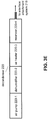
- FIG. 5 illustrates an exemplary method 300 of operating the ophthalmic docking system 200.
- the method of ophthalmic docking 300 can include: a providing 310 of a patient interface having a contact lens and coupled to a decondenser; a generating 320 of a decondensing gas flow by the decondenser for the contact lens prior to a docking of the patient interface to an eye; and a docking 330 of the patient interface to the eye.
- the patient interface can be the PI 210
- the contact lens can be the contact lens 216
- the decondenser can be the decondenser 220.
- the generating 320 can include generating a heated airflow by an air pump and an air heater, such as the air pump 220-1 and the air heater 220-3. In some examples, the generating 320 can include generating a dehumidified airflow by the air pump 220-1 and a dehumidifier, such as the dehumidifier 220-2. In some examples, the generating 320 can include generating a pressure-regulated airflow by the air pump220-1, the reservoir 220-4 and possibly by the pressure regulator 220-5.
- FIG. 6 illustrates that some embodiments of the ophthalmic docking system 200 can include a patient interface 210 where the proximal portion 212 and the distal portion 214 are separate elements.
- the distal portion 214 can be coupled to the elements 216-230 of the embodiment of FIG. 4B , including the valve 230, the decondenser 220, and the vacuum-suction pump 218-1.
- An advantage of such two-piece PIs is that the distal portion 214 may be more easily aligned and docked with the eye than the one-piece PIs, since the alignment does not require the adjustment of the objective 122 of the optic 120 by the gantry 152.
- the proximal portion 212 and the distal portion 214 needs to be coupled together after the distal portion 214 has been attached to the eye. Therefore, the coupling is typically performed by the surgeon and not as part of the manufacturing process. This in-situ coupling can possibly lead to imprecision of the alignment of the distal portion 214 and especially its contact lens 216 with the optic 120 of the laser system 100. To offer improved precision and ease of this coupling process, some embodiments can include a grip system to mechanically maneuver the distal portion 214 more precisely during the alignment and the coupling.
- FIG. 7 illustrates another example of the ophthalmic docking or interface system 200 that can include the patient interface 210, attachable to the ophthalmic surgical laser system 100 through its objective 122.
- the PI 210 can include the contact lens 216 to be docked to the eye 1.
- the interface system 200 can further include a desiccating or decondenser system 220 that can direct a desiccating gas flow to a chamber formed at the contact lens 216.
- Examples of the patient interface 210 can include an interface attachment system 218 that includes a set of contact pads 218-4. These contact pads 218-4 concentrate the force pressing the PI 210 to the eye 1 onto small areas, thus increasing the pressure. The increased pressure can press the contact pads 218-4 deep into a corneal tissue, thus making the attachment of the PI 210 to the eye 1 firm. Such examples can be simple as they attach the PI 210 to the eye only by the mechanical pressure of the contact pads 218-4 instead of vacuum suction systems.
- the PI 210 can include the vacuum-suction ring 218-1 to facilitate the attachment of the PI 210 to the eye 1, and the ophthalmic interface system 200 can include the vacuum-suction pump 218-2 to provide vacuum suction.
- the desiccating gas of the desiccator 220 and the vacuum suction of the vacuum-suction pump 218-2 can be provided through the same hose or tubing to the patient interface 210.
Landscapes
- Health & Medical Sciences (AREA)
- Ophthalmology & Optometry (AREA)
- Optics & Photonics (AREA)
- Physics & Mathematics (AREA)
- Life Sciences & Earth Sciences (AREA)
- Public Health (AREA)
- Engineering & Computer Science (AREA)
- Biomedical Technology (AREA)
- Heart & Thoracic Surgery (AREA)
- Vascular Medicine (AREA)
- Nuclear Medicine, Radiotherapy & Molecular Imaging (AREA)
- Animal Behavior & Ethology (AREA)
- General Health & Medical Sciences (AREA)
- Surgery (AREA)
- Veterinary Medicine (AREA)
- Thermotherapy And Cooling Therapy Devices (AREA)
- Prostheses (AREA)
- Laser Surgery Devices (AREA)
- Radiation-Therapy Devices (AREA)
- Eyeglasses (AREA)
- Eye Examination Apparatus (AREA)
Applications Claiming Priority (2)
| Application Number | Priority Date | Filing Date | Title |
|---|---|---|---|
| US13/197,071 US8939967B2 (en) | 2011-08-03 | 2011-08-03 | Patient interface defogger |
| PCT/US2012/049319 WO2013019944A1 (en) | 2011-08-03 | 2012-08-02 | Patient interface defogger |
Publications (2)
| Publication Number | Publication Date |
|---|---|
| EP2720658A1 EP2720658A1 (en) | 2014-04-23 |
| EP2720658B1 true EP2720658B1 (en) | 2016-04-27 |
Family
ID=46642646
Family Applications (1)
| Application Number | Title | Priority Date | Filing Date |
|---|---|---|---|
| EP12745970.9A Active EP2720658B1 (en) | 2011-08-03 | 2012-08-02 | Patient interface defogger |
Country Status (11)
| Country | Link |
|---|---|
| US (1) | US8939967B2 (enExample) |
| EP (1) | EP2720658B1 (enExample) |
| JP (1) | JP5993008B2 (enExample) |
| KR (1) | KR101927480B1 (enExample) |
| CN (1) | CN103717183B (enExample) |
| AU (1) | AU2012290073B2 (enExample) |
| BR (1) | BR112014002157A2 (enExample) |
| CA (1) | CA2842343C (enExample) |
| ES (1) | ES2575703T3 (enExample) |
| MX (1) | MX340770B (enExample) |
| WO (1) | WO2013019944A1 (enExample) |
Families Citing this family (21)
| Publication number | Priority date | Publication date | Assignee | Title |
|---|---|---|---|---|
| CA2811988C (en) | 2010-09-02 | 2016-11-01 | Optimedica Corporation | Patient interface for ophthalmologic diagnostic and interventional procedures |
| US8863749B2 (en) | 2011-10-21 | 2014-10-21 | Optimedica Corporation | Patient interface for ophthalmologic diagnostic and interventional procedures |
| US9044302B2 (en) | 2011-10-21 | 2015-06-02 | Optimedica Corp. | Patient interface for ophthalmologic diagnostic and interventional procedures |
| US9237967B2 (en) | 2011-10-21 | 2016-01-19 | Optimedica Corporation | Patient interface for ophthalmologic diagnostic and interventional procedures |
| JP6202252B2 (ja) * | 2012-06-02 | 2017-09-27 | 株式会社ニデック | 眼科用レーザ手術装置 |
| WO2014038677A1 (ja) * | 2012-09-07 | 2014-03-13 | 出光興産株式会社 | 新規芳香族複素環誘導体、有機エレクトロルミネッセンス素子用材料、有機エレクトロルミネッセンス素子用材料溶液及び有機エレクトロルミネッセンス素子 |
| KR101452391B1 (ko) * | 2013-03-05 | 2014-10-23 | 가톨릭대학교 산학협력단 | 도킹 유니트가 구비된 안과 수술 시스템 및 디스플레이 방법 |
| JP6403661B2 (ja) * | 2015-12-28 | 2018-10-10 | キヤノンファインテックニスカ株式会社 | 画像形成装置 |
| US10219948B2 (en) | 2016-02-24 | 2019-03-05 | Perfect Ip, Llc | Ophthalmic laser treatment system and method |
| WO2017191538A1 (en) * | 2016-05-05 | 2017-11-09 | Novartis Ag | Fogging prevention for surgical contact lenses |
| EP3471675B1 (en) | 2016-08-01 | 2021-09-15 | Alcon Inc. | Integrated ophthalmic surgical system |
| US10952599B2 (en) | 2017-09-13 | 2021-03-23 | Ricoh Company, Ltd. | Active lens defogging for digital imaging systems |
| US11246754B2 (en) | 2018-07-16 | 2022-02-15 | Vialase, Inc. | Surgical system and procedure for treatment of the trabecular meshwork and Schlemm's canal using a femtosecond laser |
| KR102668688B1 (ko) | 2018-07-23 | 2024-05-24 | 삼성디스플레이 주식회사 | 유기 발광 소자 |
| WO2020058198A1 (en) | 2018-09-20 | 2020-03-26 | Ivis Technologies S.R.L | Apparatus for controlled plume evacuation |
| KR102661468B1 (ko) | 2019-02-15 | 2024-04-30 | 삼성디스플레이 주식회사 | 유기 발광 소자 및 이를 포함한 전자 장치 |
| US20210151691A1 (en) | 2019-11-14 | 2021-05-20 | Samsung Display Co., Ltd. | Organic light-emitting device and apparatus including the same |
| AU2020401393A1 (en) | 2019-12-14 | 2022-08-04 | Vialase, Inc. | Near eye reflective devices for diagnostic and therapeutic ophthalmic procedures |
| US11564567B2 (en) | 2020-02-04 | 2023-01-31 | Vialase, Inc. | System and method for locating a surface of ocular tissue for glaucoma surgery based on dual aiming beams |
| US11612315B2 (en) | 2020-04-09 | 2023-03-28 | Vialase, Inc. | Alignment and diagnostic device and methods for imaging and surgery at the irido-corneal angle of the eye |
| CA3191936A1 (en) * | 2020-09-25 | 2022-03-31 | Mario Abraham | Adjusting moisture conditions for ophthalmic laser ablation surgery |
Family Cites Families (89)
| Publication number | Priority date | Publication date | Assignee | Title |
|---|---|---|---|---|
| US3706304A (en) | 1970-02-19 | 1972-12-19 | Hampson A Sisler | Optical ophthalmodynamometer |
| US4367018A (en) | 1979-05-08 | 1983-01-04 | Konan Camera Research Institute | Eyeball microscope |
| US4453546A (en) | 1982-09-27 | 1984-06-12 | The United States Of America As Reprsented By The Secretary Of The Army | Scleral depressor |
| US4718418A (en) | 1983-11-17 | 1988-01-12 | Lri L.P. | Apparatus for ophthalmological surgery |
| US4600008A (en) | 1984-01-09 | 1986-07-15 | Schmidt Richard G | Instrument for removing foreign substances from the eye |
| US4964717A (en) | 1984-03-16 | 1990-10-23 | The Trustees Of Columbia University In The City Of New York | Ophthalmic image stabilization system |
| US4753526A (en) | 1984-03-16 | 1988-06-28 | The Trustees Of Columbia University In The City Of New York | Ophthalmic image stabilization system |
| DE3638226A1 (de) | 1986-11-08 | 1988-05-11 | Rodenstock Instr | Vorrichtung zur beobachtung der hinteren augenabschnitte |
| GB8606821D0 (en) | 1986-03-19 | 1986-04-23 | Pa Consulting Services | Corneal reprofiling |
| US5423801A (en) | 1986-03-19 | 1995-06-13 | Summit Technology, Inc. | Laser corneal surgery |
| US5324281A (en) | 1987-03-09 | 1994-06-28 | Summit Technology, Inc. | Laser reprofiling system employing a photodecomposable mask |
| WO1989006519A2 (en) | 1988-01-25 | 1989-07-27 | Refractive Laser Research & Development Program, L | Method and apparatus for laser surgery |
| US5112328A (en) | 1988-01-25 | 1992-05-12 | Refractive Laser Research & Development Program, Ltd. | Method and apparatus for laser surgery |
| US4905711A (en) | 1988-03-08 | 1990-03-06 | Taunton Technologies, Inc. | Eye restraining device |
| US4907586A (en) | 1988-03-31 | 1990-03-13 | Intelligent Surgical Lasers | Method for reshaping the eye |
| US5364390A (en) | 1988-05-19 | 1994-11-15 | Refractive Laser Research And Development, Inc. | Handpiece and related apparatus for laser surgery and dentistry |
| DE3838253A1 (de) | 1988-11-11 | 1990-05-23 | Krumeich Joerg H | Saugring fuer operationen am menschlichen auge |
| DE3919985A1 (de) | 1989-06-19 | 1990-12-20 | Rodenstock Instr | Kontaktglas |
| US5196027A (en) | 1990-05-02 | 1993-03-23 | Thompson Keith P | Apparatus and process for application and adjustable reprofiling of synthetic lenticules for vision correction |
| US6342053B1 (en) | 1990-07-23 | 2002-01-29 | Laser Biotech, Inc. | Apparatus for cornea reshaping |
| US5128509A (en) | 1990-09-04 | 1992-07-07 | Reliant Laser Corp. | Method and apparatus for transforming and steering laser beams |
| JP3206923B2 (ja) | 1991-01-30 | 2001-09-10 | 株式会社ニデック | 眼科用レーザ手術装置 |
| US5280491A (en) | 1991-08-02 | 1994-01-18 | Lai Shui T | Two dimensional scan amplifier laser |
| JP3164236B2 (ja) | 1991-10-04 | 2001-05-08 | 株式会社ニデック | 光治療装置 |
| DE69221806T2 (de) | 1991-10-10 | 1998-03-26 | Coherent Inc | Vorrichtung zum Abgeben eines defokussierten Laserstrahls mit scharfkantigem Querschnitt |
| RU94030810A (ru) | 1991-11-06 | 1996-06-20 | Т.Лай Шуй | Импульсный лазерный аппарат, способ для обеспечения гладкой абляции вещества, лазерный аппарат и способ роговичной хирургии |
| EP0625271A4 (en) | 1992-01-17 | 1995-01-04 | Trimedyne Inc | METHOD AND APPARATUS FOR TRANSMITTING LASER RADIATION. |
| AU678967B2 (en) | 1992-04-10 | 1997-06-19 | Premier Laser Systems, Inc. | Apparatus and method for performing eye surgery |
| IL103290A (en) | 1992-09-25 | 1996-06-18 | Ben Nun Joshua | Ophthalmologic examination and/or treatment apparatus |
| US6090100A (en) | 1992-10-01 | 2000-07-18 | Chiron Technolas Gmbh Ophthalmologische Systeme | Excimer laser system for correction of vision with reduced thermal effects |
| US5549632A (en) | 1992-10-26 | 1996-08-27 | Novatec Laser Systems, Inc. | Method and apparatus for ophthalmic surgery |
| JPH06154264A (ja) * | 1992-11-20 | 1994-06-03 | Akio Okamoto | 眼球角膜手術装置 |
| US5616139A (en) | 1992-11-20 | 1997-04-01 | Shinseiro Okamoto | Method and apparatus for operating a cornea |
| US5336215A (en) | 1993-01-22 | 1994-08-09 | Intelligent Surgical Lasers | Eye stabilizing mechanism for use in ophthalmic laser surgery |
| US5360424A (en) | 1993-06-04 | 1994-11-01 | Summit Technology, Inc. | Tracking system for laser surgery |
| US5957832A (en) | 1993-10-08 | 1999-09-28 | Heartport, Inc. | Stereoscopic percutaneous visualization system |
| US5656186A (en) | 1994-04-08 | 1997-08-12 | The Regents Of The University Of Michigan | Method for controlling configuration of laser induced breakdown and ablation |
| US5861955A (en) | 1994-04-25 | 1999-01-19 | Medjet Inc. | Topographical cornea mapping for corneal vision correction |
| IT1274984B (it) | 1994-12-09 | 1997-07-29 | Technopharma Sa | Soluzioni viscosizzate con ialuronato di sodio per l'uso come fluido maschera nella fotocheratectomia terapeutica mediante laser a accimeri |
| US6019472A (en) | 1997-05-12 | 2000-02-01 | Koester; Charles J. | Contact lens element for examination or treatment of ocular tissues |
| US6143010A (en) | 1997-07-18 | 2000-11-07 | Kera Vision Inc. | Corneal vacuum centering device |
| US6623476B2 (en) | 1998-10-15 | 2003-09-23 | Intralase Corp. | Device and method for reducing corneal induced aberrations during ophthalmic laser surgery |
| US6254595B1 (en) | 1998-10-15 | 2001-07-03 | Intralase Corporation | Corneal aplanation device |
| US6344040B1 (en) | 1999-03-11 | 2002-02-05 | Intralase Corporation | Device and method for removing gas and debris during the photodisruption of stromal tissue |
| US6373571B1 (en) | 1999-03-11 | 2002-04-16 | Intralase Corp. | Disposable contact lens for use with an ophthalmic laser system |
| IL129227A0 (en) | 1999-03-29 | 2000-02-17 | Talia Technology Ltd | A disposable diagnostic contact lens |
| EP1182979B1 (de) | 1999-06-07 | 2005-08-17 | Carl Zeiss Meditec AG | Vorrichtung zum absaugen von abprodukten bei der ablation von biologischem gewebe |
| US6412334B1 (en) | 2000-02-07 | 2002-07-02 | Steris Inc. | Leak detector for endoscopes |
| US6458141B1 (en) | 2000-03-10 | 2002-10-01 | Gholam A. Peyman | Method and apparatus for creating a flap in the cornea and incisions or shrinkage under the flap to correct vision disorders |
| US6436113B1 (en) | 2000-09-18 | 2002-08-20 | Thomas A. Burba | Eye positioner |
| AU9481801A (en) | 2000-09-26 | 2002-04-08 | Calhoun Vision Inc | Power adjustment of adjustable lens |
| US6730073B2 (en) | 2000-10-20 | 2004-05-04 | Medtronic, Inc. | Method of performing a lasik procedure and tonometer system for use therewith |
| US6863667B2 (en) | 2001-01-29 | 2005-03-08 | Intralase Corp. | Ocular fixation and stabilization device for ophthalmic surgical applications |
| US20080071254A1 (en) * | 2001-01-29 | 2008-03-20 | Advanced Medical Optics, Inc. | Ophthalmic interface apparatus and system and method of interfacing a surgical laser with an eye |
| US6899707B2 (en) | 2001-01-29 | 2005-05-31 | Intralase Corp. | Applanation lens and method for ophthalmic surgical applications |
| US6451006B1 (en) | 2001-02-14 | 2002-09-17 | 20/10 Perfect Vision Optische Geraete Gmbh | Method for separating lamellae |
| US6579282B2 (en) | 2001-04-25 | 2003-06-17 | 20/10 Perfect Vision Optische Geraete Gmbh | Device and method for creating a corneal reference for an eyetracker |
| US6733491B2 (en) | 2001-09-07 | 2004-05-11 | Advanced Medical Optics | Cataract extraction apparatus and method |
| JP3613634B2 (ja) | 2001-11-06 | 2005-01-26 | 得一郎 長谷川 | 視力矯正装置 |
| US6641577B2 (en) | 2001-11-28 | 2003-11-04 | 20/10 Perfect Vision Optische Geraete Gmbh | Apparatus and method for creating a corneal flap |
| US6776824B2 (en) | 2002-01-11 | 2004-08-17 | Sheree H. Wen | Antiviral and antibacterial filtration module for a vacuum cleaner or other appliance |
| US20030153904A1 (en) | 2002-02-13 | 2003-08-14 | Patel Anilbhai S. | Environmental chamber for laser refractive surgery |
| US6730074B2 (en) | 2002-05-24 | 2004-05-04 | 20/10 Perfect Vision Optische Geraete Gmbh | Cornea contact system for laser surgery |
| AU2003268558B2 (en) | 2002-09-09 | 2009-01-08 | Alexander Dybbs | Ophthalmic surgical system |
| US6992765B2 (en) | 2002-10-11 | 2006-01-31 | Intralase Corp. | Method and system for determining the alignment of a surface of a material in relation to a laser beam |
| US7244026B1 (en) | 2002-10-18 | 2007-07-17 | Volk Optical, Inc. | Sterilizable ophthalmoscopy lens system |
| DE10300091A1 (de) | 2003-01-04 | 2004-07-29 | Lubatschowski, Holger, Dr. | Mikrotom |
| US6942343B2 (en) | 2003-04-07 | 2005-09-13 | Arkadiy Farberov | Optical device for intraocular observation |
| EP1486185B1 (de) | 2003-06-10 | 2006-09-27 | SIE AG, Surgical Instrument Engineering | Opthalmologische Vorrichtung für die Auflösung von Augengewebe |
| US7285096B2 (en) | 2003-11-12 | 2007-10-23 | Esi, Inc. | Ultrasound probe positioning immersion shell |
| DE10353264B4 (de) | 2003-11-14 | 2022-07-07 | Carl Zeiss Meditec Ag | Adapter zum Koppeln einer Laserbearbeitungsvorrichtung mit einem Objekt |
| US7402159B2 (en) | 2004-03-01 | 2008-07-22 | 20/10 Perfect Vision Optische Geraete Gmbh | System and method for positioning a patient for laser surgery |
| AU2005230803B8 (en) | 2004-04-05 | 2010-06-24 | Fisher & Paykel Healthcare Limited | Scope warming device |
| US7238176B2 (en) | 2004-04-29 | 2007-07-03 | 20/10 Perfect Vision Optische Geraete Gmbh | Method for intrastromal photodisruption of dome-shaped surfaces |
| US7452080B2 (en) | 2004-06-10 | 2008-11-18 | Optimedica Corporation | Scanning ophthalmic fixation method and apparatus |
| US20050143718A1 (en) | 2004-12-02 | 2005-06-30 | Sie Ag Surgical Instrument Engineering | Method for surgical treatment of a patient's eye by means of a laser |
| US7390089B2 (en) | 2005-02-25 | 2008-06-24 | 20/10 Perfect Vision Optische Geraete Gmbh | Device and method for aligning an eye with a surgical laser |
| JP4879897B2 (ja) | 2005-05-10 | 2012-02-22 | 卓也 片岡 | 眼科レーザー治療用器具 |
| CN100556384C (zh) * | 2005-05-10 | 2009-11-04 | 片岡卓也 | 一种眼科激光治疗装置 |
| US7955324B2 (en) | 2005-10-21 | 2011-06-07 | Technolas Perfect Vision Gmbh | Cornea contact system |
| US7611507B2 (en) | 2005-10-24 | 2009-11-03 | Amo Development Llc | Disposable patient interface |
| US20070173791A1 (en) | 2006-01-20 | 2007-07-26 | Intralase Corp. | System for ophthalmic laser surgery |
| MX2008009437A (es) | 2006-01-24 | 2009-06-22 | Page 65 Sl | Laringoscopio optico luminoso. |
| US8512236B2 (en) | 2008-01-11 | 2013-08-20 | Oraya Therapeutics, Inc. | System and method for positioning and stabilizing an eye |
| DE112008002446T5 (de) | 2007-09-10 | 2010-06-24 | LenSx Lasers, Inc., Aliso Viejo | Vorrichtungen, Systeme und Techniken zur Kopplung mit einem Auge in der Laserchirurgie |
| AU2008347866A1 (en) | 2008-01-16 | 2009-07-23 | Tokuichiro Hasegawa | Vision corrective jig and cooling fluid injection tool for the jig |
| US8070290B2 (en) | 2008-12-17 | 2011-12-06 | Glaukos Corporation | Gonioscope for improved viewing |
| WO2011094493A1 (en) | 2010-01-29 | 2011-08-04 | Lensar, Inc. | Servo controlled docking force device for use in ophthalmic applications |
| US8845624B2 (en) | 2010-06-25 | 2014-09-30 | Alcon LexSx, Inc. | Adaptive patient interface |
-
2011
- 2011-08-03 US US13/197,071 patent/US8939967B2/en active Active
-
2012
- 2012-08-02 KR KR1020147005367A patent/KR101927480B1/ko not_active Expired - Fee Related
- 2012-08-02 CA CA2842343A patent/CA2842343C/en not_active Expired - Fee Related
- 2012-08-02 EP EP12745970.9A patent/EP2720658B1/en active Active
- 2012-08-02 AU AU2012290073A patent/AU2012290073B2/en not_active Ceased
- 2012-08-02 BR BR112014002157A patent/BR112014002157A2/pt not_active Application Discontinuation
- 2012-08-02 JP JP2014524072A patent/JP5993008B2/ja active Active
- 2012-08-02 WO PCT/US2012/049319 patent/WO2013019944A1/en not_active Ceased
- 2012-08-02 ES ES12745970.9T patent/ES2575703T3/es active Active
- 2012-08-02 CN CN201280038028.3A patent/CN103717183B/zh not_active Expired - Fee Related
- 2012-08-02 MX MX2014001116A patent/MX340770B/es active IP Right Grant
Also Published As
| Publication number | Publication date |
|---|---|
| KR20140050697A (ko) | 2014-04-29 |
| WO2013019944A1 (en) | 2013-02-07 |
| US20130035672A1 (en) | 2013-02-07 |
| AU2012290073A1 (en) | 2014-02-06 |
| CN103717183A (zh) | 2014-04-09 |
| EP2720658A1 (en) | 2014-04-23 |
| JP5993008B2 (ja) | 2016-09-14 |
| MX340770B (es) | 2016-07-26 |
| CN103717183B (zh) | 2016-08-17 |
| KR101927480B1 (ko) | 2018-12-11 |
| US8939967B2 (en) | 2015-01-27 |
| CA2842343C (en) | 2019-03-12 |
| CA2842343A1 (en) | 2013-02-07 |
| ES2575703T3 (es) | 2016-06-30 |
| JP2014525803A (ja) | 2014-10-02 |
| AU2012290073B2 (en) | 2016-05-12 |
| MX2014001116A (es) | 2014-02-27 |
| BR112014002157A2 (pt) | 2017-02-21 |
Similar Documents
| Publication | Publication Date | Title |
|---|---|---|
| EP2720658B1 (en) | Patient interface defogger | |
| US7390089B2 (en) | Device and method for aligning an eye with a surgical laser | |
| US20110190739A1 (en) | Servo controlled docking force device for use in ophthalmic applications | |
| CN104114131A (zh) | 具可变扁平角膜的患者接口 | |
| US20120069302A1 (en) | Electronically Controlled Fixation Light for Ophthalmic Imaging Systems | |
| US20170189228A1 (en) | Real-Time Laser Modulation And Delivery In Ophthalmic Devices For Scanning, Imaging, And Laser Treatment Of The Eye | |
| US7951138B2 (en) | Pivoting roller tip for dermatological treatment apparatus | |
| US10369055B2 (en) | Modular patient adapter for an eye laser device | |
| TW200811724A (en) | Adaptive pattern correction for laser scanners | |
| AU2017322503B2 (en) | Eye tissue measurements | |
| JP2015195921A5 (enExample) | ||
| JP7328963B2 (ja) | 光調節可能眼内レンズ照射システムのための患者インタフェース | |
| US20130060254A1 (en) | Eye manipulator | |
| WO2001021096A3 (en) | Two-pivot scanning for laser eye surgery | |
| US20250127535A1 (en) | System, method, and devices for tissue manipulation using electronically steerable ultrasound transducer |
Legal Events
| Date | Code | Title | Description |
|---|---|---|---|
| PUAI | Public reference made under article 153(3) epc to a published international application that has entered the european phase |
Free format text: ORIGINAL CODE: 0009012 |
|
| 17P | Request for examination filed |
Effective date: 20140115 |
|
| AK | Designated contracting states |
Kind code of ref document: A1 Designated state(s): AL AT BE BG CH CY CZ DE DK EE ES FI FR GB GR HR HU IE IS IT LI LT LU LV MC MK MT NL NO PL PT RO RS SE SI SK SM TR |
|
| 17Q | First examination report despatched |
Effective date: 20150310 |
|
| GRAP | Despatch of communication of intention to grant a patent |
Free format text: ORIGINAL CODE: EPIDOSNIGR1 |
|
| INTG | Intention to grant announced |
Effective date: 20151113 |
|
| GRAS | Grant fee paid |
Free format text: ORIGINAL CODE: EPIDOSNIGR3 |
|
| GRAA | (expected) grant |
Free format text: ORIGINAL CODE: 0009210 |
|
| AK | Designated contracting states |
Kind code of ref document: B1 Designated state(s): AL AT BE BG CH CY CZ DE DK EE ES FI FR GB GR HR HU IE IS IT LI LT LU LV MC MK MT NL NO PL PT RO RS SE SI SK SM TR |
|
| REG | Reference to a national code |
Ref country code: GB Ref legal event code: FG4D |
|
| REG | Reference to a national code |
Ref country code: CH Ref legal event code: EP |
|
| REG | Reference to a national code |
Ref country code: AT Ref legal event code: REF Ref document number: 793932 Country of ref document: AT Kind code of ref document: T Effective date: 20160515 |
|
| REG | Reference to a national code |
Ref country code: IE Ref legal event code: FG4D |
|
| REG | Reference to a national code |
Ref country code: DE Ref legal event code: R096 Ref document number: 602012017727 Country of ref document: DE |
|
| REG | Reference to a national code |
Ref country code: ES Ref legal event code: FG2A Ref document number: 2575703 Country of ref document: ES Kind code of ref document: T3 Effective date: 20160630 |
|
| REG | Reference to a national code |
Ref country code: FR Ref legal event code: PLFP Year of fee payment: 5 |
|
| REG | Reference to a national code |
Ref country code: LT Ref legal event code: MG4D |
|
| REG | Reference to a national code |
Ref country code: NL Ref legal event code: MP Effective date: 20160427 |
|
| REG | Reference to a national code |
Ref country code: AT Ref legal event code: MK05 Ref document number: 793932 Country of ref document: AT Kind code of ref document: T Effective date: 20160427 |
|
| PG25 | Lapsed in a contracting state [announced via postgrant information from national office to epo] |
Ref country code: NL Free format text: LAPSE BECAUSE OF FAILURE TO SUBMIT A TRANSLATION OF THE DESCRIPTION OR TO PAY THE FEE WITHIN THE PRESCRIBED TIME-LIMIT Effective date: 20160427 |
|
| PG25 | Lapsed in a contracting state [announced via postgrant information from national office to epo] |
Ref country code: LT Free format text: LAPSE BECAUSE OF FAILURE TO SUBMIT A TRANSLATION OF THE DESCRIPTION OR TO PAY THE FEE WITHIN THE PRESCRIBED TIME-LIMIT Effective date: 20160427 Ref country code: PL Free format text: LAPSE BECAUSE OF FAILURE TO SUBMIT A TRANSLATION OF THE DESCRIPTION OR TO PAY THE FEE WITHIN THE PRESCRIBED TIME-LIMIT Effective date: 20160427 Ref country code: FI Free format text: LAPSE BECAUSE OF FAILURE TO SUBMIT A TRANSLATION OF THE DESCRIPTION OR TO PAY THE FEE WITHIN THE PRESCRIBED TIME-LIMIT Effective date: 20160427 Ref country code: NO Free format text: LAPSE BECAUSE OF FAILURE TO SUBMIT A TRANSLATION OF THE DESCRIPTION OR TO PAY THE FEE WITHIN THE PRESCRIBED TIME-LIMIT Effective date: 20160727 |
|
| PG25 | Lapsed in a contracting state [announced via postgrant information from national office to epo] |
Ref country code: LV Free format text: LAPSE BECAUSE OF FAILURE TO SUBMIT A TRANSLATION OF THE DESCRIPTION OR TO PAY THE FEE WITHIN THE PRESCRIBED TIME-LIMIT Effective date: 20160427 Ref country code: RS Free format text: LAPSE BECAUSE OF FAILURE TO SUBMIT A TRANSLATION OF THE DESCRIPTION OR TO PAY THE FEE WITHIN THE PRESCRIBED TIME-LIMIT Effective date: 20160427 Ref country code: GR Free format text: LAPSE BECAUSE OF FAILURE TO SUBMIT A TRANSLATION OF THE DESCRIPTION OR TO PAY THE FEE WITHIN THE PRESCRIBED TIME-LIMIT Effective date: 20160728 Ref country code: AT Free format text: LAPSE BECAUSE OF FAILURE TO SUBMIT A TRANSLATION OF THE DESCRIPTION OR TO PAY THE FEE WITHIN THE PRESCRIBED TIME-LIMIT Effective date: 20160427 Ref country code: SE Free format text: LAPSE BECAUSE OF FAILURE TO SUBMIT A TRANSLATION OF THE DESCRIPTION OR TO PAY THE FEE WITHIN THE PRESCRIBED TIME-LIMIT Effective date: 20160427 Ref country code: PT Free format text: LAPSE BECAUSE OF FAILURE TO SUBMIT A TRANSLATION OF THE DESCRIPTION OR TO PAY THE FEE WITHIN THE PRESCRIBED TIME-LIMIT Effective date: 20160829 Ref country code: HR Free format text: LAPSE BECAUSE OF FAILURE TO SUBMIT A TRANSLATION OF THE DESCRIPTION OR TO PAY THE FEE WITHIN THE PRESCRIBED TIME-LIMIT Effective date: 20160427 |
|
| PG25 | Lapsed in a contracting state [announced via postgrant information from national office to epo] |
Ref country code: BE Free format text: LAPSE BECAUSE OF FAILURE TO SUBMIT A TRANSLATION OF THE DESCRIPTION OR TO PAY THE FEE WITHIN THE PRESCRIBED TIME-LIMIT Effective date: 20160427 |
|
| REG | Reference to a national code |
Ref country code: DE Ref legal event code: R097 Ref document number: 602012017727 Country of ref document: DE |
|
| PG25 | Lapsed in a contracting state [announced via postgrant information from national office to epo] |
Ref country code: EE Free format text: LAPSE BECAUSE OF FAILURE TO SUBMIT A TRANSLATION OF THE DESCRIPTION OR TO PAY THE FEE WITHIN THE PRESCRIBED TIME-LIMIT Effective date: 20160427 Ref country code: RO Free format text: LAPSE BECAUSE OF FAILURE TO SUBMIT A TRANSLATION OF THE DESCRIPTION OR TO PAY THE FEE WITHIN THE PRESCRIBED TIME-LIMIT Effective date: 20160427 Ref country code: SK Free format text: LAPSE BECAUSE OF FAILURE TO SUBMIT A TRANSLATION OF THE DESCRIPTION OR TO PAY THE FEE WITHIN THE PRESCRIBED TIME-LIMIT Effective date: 20160427 Ref country code: CZ Free format text: LAPSE BECAUSE OF FAILURE TO SUBMIT A TRANSLATION OF THE DESCRIPTION OR TO PAY THE FEE WITHIN THE PRESCRIBED TIME-LIMIT Effective date: 20160427 Ref country code: DK Free format text: LAPSE BECAUSE OF FAILURE TO SUBMIT A TRANSLATION OF THE DESCRIPTION OR TO PAY THE FEE WITHIN THE PRESCRIBED TIME-LIMIT Effective date: 20160427 |
|
| PG25 | Lapsed in a contracting state [announced via postgrant information from national office to epo] |
Ref country code: SM Free format text: LAPSE BECAUSE OF FAILURE TO SUBMIT A TRANSLATION OF THE DESCRIPTION OR TO PAY THE FEE WITHIN THE PRESCRIBED TIME-LIMIT Effective date: 20160427 |
|
| PLBE | No opposition filed within time limit |
Free format text: ORIGINAL CODE: 0009261 |
|
| STAA | Information on the status of an ep patent application or granted ep patent |
Free format text: STATUS: NO OPPOSITION FILED WITHIN TIME LIMIT |
|
| PG25 | Lapsed in a contracting state [announced via postgrant information from national office to epo] |
Ref country code: MC Free format text: LAPSE BECAUSE OF FAILURE TO SUBMIT A TRANSLATION OF THE DESCRIPTION OR TO PAY THE FEE WITHIN THE PRESCRIBED TIME-LIMIT Effective date: 20160427 |
|
| REG | Reference to a national code |
Ref country code: CH Ref legal event code: PL |
|
| 26N | No opposition filed |
Effective date: 20170130 |
|
| PG25 | Lapsed in a contracting state [announced via postgrant information from national office to epo] |
Ref country code: LI Free format text: LAPSE BECAUSE OF NON-PAYMENT OF DUE FEES Effective date: 20160831 Ref country code: CH Free format text: LAPSE BECAUSE OF NON-PAYMENT OF DUE FEES Effective date: 20160831 |
|
| PG25 | Lapsed in a contracting state [announced via postgrant information from national office to epo] |
Ref country code: SI Free format text: LAPSE BECAUSE OF FAILURE TO SUBMIT A TRANSLATION OF THE DESCRIPTION OR TO PAY THE FEE WITHIN THE PRESCRIBED TIME-LIMIT Effective date: 20160427 |
|
| REG | Reference to a national code |
Ref country code: IE Ref legal event code: MM4A |
|
| REG | Reference to a national code |
Ref country code: FR Ref legal event code: PLFP Year of fee payment: 6 |
|
| PG25 | Lapsed in a contracting state [announced via postgrant information from national office to epo] |
Ref country code: IE Free format text: LAPSE BECAUSE OF NON-PAYMENT OF DUE FEES Effective date: 20160802 |
|
| PG25 | Lapsed in a contracting state [announced via postgrant information from national office to epo] |
Ref country code: LU Free format text: LAPSE BECAUSE OF NON-PAYMENT OF DUE FEES Effective date: 20160802 |
|
| PG25 | Lapsed in a contracting state [announced via postgrant information from national office to epo] |
Ref country code: HU Free format text: LAPSE BECAUSE OF FAILURE TO SUBMIT A TRANSLATION OF THE DESCRIPTION OR TO PAY THE FEE WITHIN THE PRESCRIBED TIME-LIMIT; INVALID AB INITIO Effective date: 20120802 Ref country code: CY Free format text: LAPSE BECAUSE OF FAILURE TO SUBMIT A TRANSLATION OF THE DESCRIPTION OR TO PAY THE FEE WITHIN THE PRESCRIBED TIME-LIMIT Effective date: 20160427 |
|
| PG25 | Lapsed in a contracting state [announced via postgrant information from national office to epo] |
Ref country code: IS Free format text: LAPSE BECAUSE OF FAILURE TO SUBMIT A TRANSLATION OF THE DESCRIPTION OR TO PAY THE FEE WITHIN THE PRESCRIBED TIME-LIMIT Effective date: 20160427 Ref country code: MK Free format text: LAPSE BECAUSE OF FAILURE TO SUBMIT A TRANSLATION OF THE DESCRIPTION OR TO PAY THE FEE WITHIN THE PRESCRIBED TIME-LIMIT Effective date: 20160427 Ref country code: MT Free format text: LAPSE BECAUSE OF NON-PAYMENT OF DUE FEES Effective date: 20160831 |
|
| REG | Reference to a national code |
Ref country code: FR Ref legal event code: PLFP Year of fee payment: 7 |
|
| PG25 | Lapsed in a contracting state [announced via postgrant information from national office to epo] |
Ref country code: BG Free format text: LAPSE BECAUSE OF FAILURE TO SUBMIT A TRANSLATION OF THE DESCRIPTION OR TO PAY THE FEE WITHIN THE PRESCRIBED TIME-LIMIT Effective date: 20160427 |
|
| PG25 | Lapsed in a contracting state [announced via postgrant information from national office to epo] |
Ref country code: TR Free format text: LAPSE BECAUSE OF FAILURE TO SUBMIT A TRANSLATION OF THE DESCRIPTION OR TO PAY THE FEE WITHIN THE PRESCRIBED TIME-LIMIT Effective date: 20160427 Ref country code: AL Free format text: LAPSE BECAUSE OF FAILURE TO SUBMIT A TRANSLATION OF THE DESCRIPTION OR TO PAY THE FEE WITHIN THE PRESCRIBED TIME-LIMIT Effective date: 20160427 |
|
| PGFP | Annual fee paid to national office [announced via postgrant information from national office to epo] |
Ref country code: IT Payment date: 20190821 Year of fee payment: 8 Ref country code: ES Payment date: 20190902 Year of fee payment: 8 |
|
| REG | Reference to a national code |
Ref country code: GB Ref legal event code: 732E Free format text: REGISTERED BETWEEN 20200213 AND 20200219 |
|
| REG | Reference to a national code |
Ref country code: ES Ref legal event code: PC2A Owner name: ALCON INC. Effective date: 20200430 |
|
| REG | Reference to a national code |
Ref country code: DE Ref legal event code: R081 Ref document number: 602012017727 Country of ref document: DE Owner name: ALCON INC., CH Free format text: FORMER OWNER: ALCON LENSX, INC., ALISO VIEJO, CALIF., US Ref country code: DE Ref legal event code: R082 Ref document number: 602012017727 Country of ref document: DE Representative=s name: K & H BONAPAT PATENTANWAELTE KOCH VON BEHREN &, DE |
|
| PG25 | Lapsed in a contracting state [announced via postgrant information from national office to epo] |
Ref country code: IT Free format text: LAPSE BECAUSE OF NON-PAYMENT OF DUE FEES Effective date: 20200802 |
|
| REG | Reference to a national code |
Ref country code: ES Ref legal event code: FD2A Effective date: 20220110 |
|
| PG25 | Lapsed in a contracting state [announced via postgrant information from national office to epo] |
Ref country code: ES Free format text: LAPSE BECAUSE OF NON-PAYMENT OF DUE FEES Effective date: 20200803 |
|
| P01 | Opt-out of the competence of the unified patent court (upc) registered |
Effective date: 20230504 |
|
| PGFP | Annual fee paid to national office [announced via postgrant information from national office to epo] |
Ref country code: DE Payment date: 20240717 Year of fee payment: 13 |
|
| PGFP | Annual fee paid to national office [announced via postgrant information from national office to epo] |
Ref country code: GB Payment date: 20240718 Year of fee payment: 13 |
|
| PGFP | Annual fee paid to national office [announced via postgrant information from national office to epo] |
Ref country code: FR Payment date: 20240726 Year of fee payment: 13 |