EP2719908A1 - Befestigungsmittel zwischen einem Bauteil und einem Bauelement - Google Patents
Befestigungsmittel zwischen einem Bauteil und einem Bauelement Download PDFInfo
- Publication number
- EP2719908A1 EP2719908A1 EP12007037.0A EP12007037A EP2719908A1 EP 2719908 A1 EP2719908 A1 EP 2719908A1 EP 12007037 A EP12007037 A EP 12007037A EP 2719908 A1 EP2719908 A1 EP 2719908A1
- Authority
- EP
- European Patent Office
- Prior art keywords
- component
- groove
- fastening means
- means according
- head
- Prior art date
- Legal status (The legal status is an assumption and is not a legal conclusion. Google has not performed a legal analysis and makes no representation as to the accuracy of the status listed.)
- Granted
Links
Images
Classifications
-
- F—MECHANICAL ENGINEERING; LIGHTING; HEATING; WEAPONS; BLASTING
- F16—ENGINEERING ELEMENTS AND UNITS; GENERAL MEASURES FOR PRODUCING AND MAINTAINING EFFECTIVE FUNCTIONING OF MACHINES OR INSTALLATIONS; THERMAL INSULATION IN GENERAL
- F16B—DEVICES FOR FASTENING OR SECURING CONSTRUCTIONAL ELEMENTS OR MACHINE PARTS TOGETHER, e.g. NAILS, BOLTS, CIRCLIPS, CLAMPS, CLIPS OR WEDGES; JOINTS OR JOINTING
- F16B37/00—Nuts or like thread-engaging members
- F16B37/04—Devices for fastening nuts to surfaces, e.g. sheets, plates
- F16B37/045—Devices for fastening nuts to surfaces, e.g. sheets, plates specially adapted for fastening in channels, e.g. sliding bolts, channel nuts
Definitions
- the invention relates to a fastening means between a component and a component, with at least one of these releasably engaging bolts.
- Usual attachment means have z. B. on the component through holes or threaded holes, while on the respective component z. B. Through holes are provided to pass through the serving for fastening bolts, which are either screwed into the threaded holes of the component or enforce the local holes and wear nuts on the protruding end.
- fasteners require in the component at a predetermined location through holes or tapped holes. The production is complicated. Through this, the position to be fixed components is specified. The assembly and any dismantling of such fixed components requires a corresponding effort, even in time.
- fastening means those are common, are permanently fixed by the components to be mounted on the component. This is done by welding, soldering or the like. Such fasteners are contrary to a disassembly of so fastened components.
- the invention has for its object to provide a fastener of the type mentioned above, which allows a quick and easy assembly and disassembly of a component-mounted components, without the need of removal or complete replacement of the component. Also, the possibility for a flexible positioning of the components on the component at the option of the installer should be opened. The manufacture of the component and / or the components is also to be simplified and made more cost-effective, including reduction of the production times.
- the object is achieved in a fastener of the type mentioned according to the invention in that the bolt carries a direction transverse to the pin axis thickened head and the component or the component contains at least one groove for this head with a head in a mounting position positively overlapping undercut ,
- the groove is formed as a T-slot, wherein the thickened head has a crossbar at the end and is thus preferably T-shaped thickened.
- the crossbar fits into the groove and, when it is contained transversely in the groove, positively overlapped by the undercut, which is formed by at least one web, which is provided on a groove flank of the groove and protrudes transversely into the groove and the Groove width reduced.
- the component may consist of a tubular profile, for. As a collector, tank, collection tank or the like. As components come z. Valves, Intake valves, exhaust valves, connecting elements. Pressure connections or the like into consideration.
- the bolts pass through holes or holes in the components and carry at the lower end of the thickened head in the form of a T-shaped cross bar.
- the bolt may be screwed with an end threaded shoulder in an internal thread of the thickened head or in special cases, be integral therewith.
- the attachment in the T-slot takes place in such a way that the crossbar is first aligned in the longitudinal direction of the groove and the bolt is rotated by about 90 degrees after insertion into the groove, such that the crossbar is now directed transversely to Nutverlauf and from the undercut of the groove in the form of transversely projecting webs is positively engaged and so overlapped that the crossbar is held in the groove.
- the user can select the fastening point for the component essentially freely. It is a quick, easy installation of a component on the component, in particular z. B. a valve on a tank, for. B. collection tank of a dust filter tank system, possible, as well as in the same way a quick and easy disassembly for damage to the device.
- the component can remain in place.
- the respective groove as an element of the fastener is simple and inexpensive to produce, for. B. in a component forming such a tube profile, which is produced by extrusion, in which at the same time also a groove or a plurality of grooves can be formed with.
- a component then z. B. aluminum.
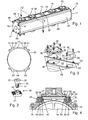
- a collection tank 10 is schematically shown as a component to which individual components 11 to 15 are releasably secured on the top side, which are designed in various ways, for. As valves, inlet elements, outlet elements, connecting elements or the like.
- an approximately tubular tank is shown here with a tubular profile 22, the end is closed by means of end covers 16, 17, the z. B. are clamped by means of longitudinally continuous longitudinal rods 18 to 21 with the tube profile 22.
- the tube profile 22 is z. B. aluminum. It has upper side and lower side each flat, flat surfaces 23 and 24 on which the individual components 11 to 15 with corresponding planar contact surface 25, 26 can be tight and tight in the attached state.
- fasteners described in more detail below are effective to serve the releasable attachment of the components 11 to 15 on the component 10, wherein the components 11 to 15, if necessary, at any time detached from the component 10, if necessary, to others Position of the component 10 attached again and generally easy and simple to assemble and disassemble.
- the component 10 requires for the attachment of the components 11 to 15 no mounting holes.
- the fasteners allow for the fitter flexibility, are simple, inexpensive and can be produced with short processing time, are straightforward and allow easy and fast assembly and disassembly of respective components 11 to 15.
- the said fastening means have on the one hand at least one, usually a plurality, on the component 10 releasably engaging pin 30.
- These bolts 30 are z. B. cylindrical, have at one end a thread 31 and at the opposite end a screw head 32, z. B. with recessed Allen tool engagement surface 33.
- Each bolt 30 includes an end-side head 40 which is thickened in the direction transverse to the pin axis, said head 40 has a cross bar 41 and is thickened in this way T-shaped. In another embodiment, not shown, the thickened head 40 may also be circular.
- the head 40 includes an internal thread 42 into which the bolt 30 with the thread 31 can be screwed.
- Part of the fastening means is further on the component 10 at least one groove 50 for the head 40 of the respective bolt 30, wherein the groove 50 has a short axial extent or, as shown in the example, a greater longitudinal extent.
- the groove 50 has a head 40 in the attachment position according to Fig. 4 positive overlapping undercut, which is realized on at least one groove flank by a transversely projecting into the groove 50, the groove width-reducing web 51 is realized.
- the groove on both sides webs 51, 52 and is formed in this way as a T-slot.
- the arrangement is such that a groove 50 of the same design is provided on the component 10 on each flat surface 23, 24, thus above and below, on both sides, the respective grooves 50 extending over the entire longitudinal extension of the tubular profile 22 and Z. B. in the production as an extrusion z. B. can be mitgesentt from aluminum.
- the device 12 on the component 10 z. B. four similar bolts 30 are provided, which are inserted into holes 27, 28 of the component 12 and inserted therethrough, and thus pass through the component 12, wherein the screw head 32 is positively received and rests. Then, a head 40 is screwed onto the end, in particular thread 31, of each bolt 30. After the component 12 is placed with its contact surface 25 on the flat surface 23, the respective bolts 30 can be sunk with end-side head 40 in the respective groove 50, wherein the head 40 is aligned with the cross bar 41 so that the crossbar in Longitudinal direction of the course of the groove 50 is located and can penetrate into the groove 50.
- the cross bar 41 is dimensioned in cross section at most as thick as the distance between the two webs 51, 52 of each groove 50, so that the cross bar 41 in this longitudinal alignment between the webs 51, 52 fits and can be sunk into the groove 50 ,
- the transverse spacing of the holes 27, 28 from each other corresponds to the transverse distance between the two upper-side grooves 50 of the surface 23 of the tube profile 22.
- Fig. 1 shows, with the aid of the fastening means described a plurality of components 11 to 15 on the component 10 releasably secured, each by means of the bolt 30 with head 40 described type and the grooves 50th
- z. B. in a defective component 11 to 15 this can be removed quickly and easily from the component 10, without the need for disassembly or the offset of the entire component 10.
- the attachment of the components 11 to 15 on the component 10 can be accomplished quickly and easily.
- the components 11 to 15 are not permanently fixedly connected to the component 10, as otherwise by welding, but releasably and quickly exchangeable.
- the tube profile 22 is fast and inexpensive to produce and requires for the attachment of the components 11 to 15 no mounting holes. By simplifying the manufacture of the assembly and the maintenance results in a cost reduction.
- a further advantage is a reduction of the components. Apart from other breakthroughs for the function in the component 10, the user is free with regard to the location of the positioning of the components 11 to 15.
- the fastening means described can also be advantageously used if, instead of the holes 27, 28, transversely directed, outwardly open slots are present in the component, through which the bolts 30 can be introduced in the transverse direction.
- the collection tank designed as a component 10 this may also consist of another component, for. As a collector, tank or the like housing.
Landscapes
- Engineering & Computer Science (AREA)
- General Engineering & Computer Science (AREA)
- Mechanical Engineering (AREA)
- Connection Of Plates (AREA)
- Valve Housings (AREA)
Abstract
Description
- Die Erfindung bezieht sich auf ein Befestigungsmittel zwischen einem Bauteil und einem Bauelement, mit zumindest einem an diesen lösbar angreifenden Bolzen.
- Übliche Befestigungsmittel weisen z. B. am Bauteil Durchgangslöcher oder Gewindebohrungen auf, während am jeweiligen Bauelement z. B. Durchgangsbohrungen vorgesehen sind, durch die zur Befestigung dienende Bolzen hindurchgreifen, die entweder in die Gewindebohrungen des Bauteiles eingeschraubt werden oder die dortigen Bohrungen durchsetzen und am herausragenden Ende Muttern tragen. Derartige Befestigungsmittel benötigen im Bauteil an vorgegebener Stelle Durchgangsbohrungen oder Gewindebohrungen. Die Herstellung ist aufwendig. Durch diese ist die Position zu befestigender Bauelemente vorgegeben. Die Montage und eine etwaige Demontage derart befestigter Bauelemente erfordert einen entsprechenden Aufwand, auch an Zeit. Als alternative Befestigungsmittel sind solche üblich, durch die am Bauteil zu befestigende Bauelemente bleibend fixiert werden. Dies geschieht durch Schweißen, Löten oder dergleichen. Derartige Befestigungen stehen einer Demontage so befestigter Bauelemente entgegen.
- Der Erfindung liegt die Aufgabe zugrunde, ein Befestigungsmittel der eingangs genannten Art zu schaffen, das eine schnelle und einfache Montage und Demontage an einem Bauteil befestigter Bauelemente gestattet, ohne die Notwendigkeit der Entfernung oder des kompletten Austauschs des Bauteils. Auch soll die Möglichkeit für eine flexible Positionierung der Bauelemente am Bauteil nach Wahl des Monteurs eröffnet werden. Die Herstellung des Bauteils und/oder der Bauelemente soll ferner vereinfacht und kostengünstiger werden einschließlich Reduzierung der Fertigungszeiten.
- Die Aufgabe ist bei einem Befestigungsmittel der eingangs genannten Art gemäß Erfindung dadurch gelöst, dass der Bolzen einen in Richtung quer zur Bolzenachse verdickten Kopf trägt und das Bauteil oder das Bauelement zumindest eine Nut für diesen Kopf mit einer den Kopf in einer Befestigungsposition formschlüssig übergreifenden Hinterschneidung enthält. In vorteilhafter Weise ist die Nut als T-Nut ausgebildet, wobei der verdickte Kopf am Ende einen Querriegel hat und so vorzugsweise T-förmig verdickt ist. Der Querriegel passt in die Nut und ist dann, wenn dieser quer in der Nut enthalten ist, formschlüssig von der Hinterschneidung übergriffen, die durch mindestens einen Steg gebildet ist, der an einer Nutflanke der Nut vorgesehen ist und quer in die Nut vorspringt und dabei die Nutbreite verkleinert. Weitere vorteilhafte Ausgestaltungen und Erfindungsmerkmale ergeben sich aus den Unteransprüchen.
- Man erkennt, dass die Verhältnisse zwischen dem Bauteil und dem mindestens einen Bauelement auch vertauscht sein können, derart, dass die Nut Bestandteil des Bauelements ist und der Bolzen das Bauteil durchsetzt und dessen endseitiger Kopf in die Nut des Bauelements formschlüssig eingreift.
- Das Bauteil kann aus einem rohrförmigen Profil, z. B. einem Sammler, Tank, Sammeltank oder dergleichen bestehen. Als Bauelemente kommen z. B. Ventile, Einlassventile, Auslassventile, Anschlußelemente. Druckanschlüsse oder dergleichen in Betracht.
- In besonders einfacher Form durchsetzen die Bolzen Durchbrüche oder Löcher in den Bauelementen und tragen am unteren Ende den verdickten Kopf in Form eines T-förmigen Querriegels. Der Bolzen kann mit einem endseitigen Gewindeabsatz in ein Innengewinde des verdickten Kopfes eingeschraubt sein oder in besonderen Anwendungsfällen auch damit einstückig sein. Die Befestigung in der T-Nut erfolgt in der Weise, dass der Querriegel zunächst in Längsrichtung der Nut ausgerichtet wird und der Bolzen nach Einbringen in die Nut um etwa 90 Grad gedreht wird, derart, dass der Querriegel nunmehr quer zum Nutverlauf gerichtet ist und von der Hinterschneidung der Nut in Form der quer vorspringenden Stege formschlüssig und so übergriffen wird, dass der Querriegel in der Nut gehalten ist. Durch Anziehen des Bolzens kann sodann das jeweilige Bauelement am Bauteil endgültig fest und dicht fixiert werden und die gewählte Position des Bauelements am Bauteil gesichert werden.
- Sieht man von etwaigen, für die Funktion notwendigen Durchbrüchen im Bauteil ab, kann der Benutzer die Befestigungsstelle für das Bauelement im wesentlichen frei auswählen. Es ist eine schnelle, einfache Montage eines Bauelements am Bauteil, insbesondere z. B. eines Ventils an einem Tank, z. B. Sammeltank eines Staubfilter-Tanksystems, möglich, wie auch in gleicher Weise eine schnelle und einfache Demontage bei Schäden am Bauelement. Dabei kann das Bauteil an Ort und Stelle verbleiben. Die jeweilige Nut als Element des Befestigungsmittels ist einfach und kostengünstig herstellbar, z. B. bei einem das Bauteil bildenden solchen Rohrprofil, das durch Extrudieren hergestellt wird, bei dem zugleich auch die eine Nut oder mehrere Nuten mit gebildet werden können. In vorteilhafter Weise besteht ein solches Bauteil dann z. B. aus Aluminium.
- Weitere Einzelheiten und Vorteile der Erfindung ergeben sich aus der nachfolgenden Beschreibung und aus den Zeichnungen.
- Die Erfindung ist nachfolgend anhand eines in den Zeichnungen gezeigten Ausführungsbeispieles näher erläutert. Es zeigen:
- Fig. 1
- eine schematische perspektivische Ansicht eines Bauteils in Gestalt eines Sammeltanks mit daran befestigten Bauelementen in Form z. B. von Tankelementen,
- Fig. 2
- eine schematische Seitenansicht mit teilweiser perspektivischer Ansicht des Bauteils mit einem Befestigungsmittel,
- Fig. 3
- eine schematische perspektivische Ansicht eines Teils des Bauteils sowie zweier daran zu befestigender Bauelemente,
- Fig. 4
- einen schematischen Schnitt mit teilweiser Seitenansicht des Sammeltanks entlang der Linie IV-IV in
Fig. 1 . - In den Zeichnungen ist schematisch ein Sammeltank als Bauteil 10 gezeigt, an dem einzelne Bauelemente 11 bis 15 oberseitig lösbar befestigt sind, die in verschiedenster Weise gestaltet sind, z. B. als Ventile, Einlasselemente, Auslasselemente, Anschlußelemente oder dergleichen.
- Als Bauteil 10 ist hier ein etwa rohrförmiger Tank mit einem Rohrprofil 22 dargestellt, der endseitig mittels Stirndeckeln 16, 17 verschlossen ist, die z. B. mittels längs durchgehender Längsstäbe 18 bis 21 mit dem Rohrprofil 22 verspannt sind. Das Rohrprofil 22 besteht z. B. aus Aluminium. Es weist oberseitig und unterseitig jeweils flache, ebene Flächen 23 und 24 auf, an denen die einzelnen Bauelemente 11 bis 15 mit entsprechenden ebenen Anlagefläche 25, 26 im angebrachten Zustand dicht und fest anliegen können.
- Zwischen dem Bauteil 10 einerseits und den einzelnen Bauelementen 11 bis 15 andererseits sind nachfolgend näher beschriebene Befestigungsmittel wirksam, die der lösbaren Befestigung der Bauelemente 11 bis 15 am Bauteil 10 dienen, wobei die Bauelemente 11 bis 15 bedarfsweise jederzeit vom Bauteil 10 gelöst, bedarfsweise an anderer Stelle des Bauteils 10 wieder angebracht und generell leicht und einfach montiert und demontiert werden können. Das Bauteil 10 benötigt für die Befestigung der Bauelemente 11 bis 15 keine Befestigungslöcher. Die Befestigungsmittel ermöglichen für den Monteur eine Flexibilität, sind einfach, kostengünstig und mit kurzer Bearbeitungszeit herstellbar, sind unkompliziert und gestatten eine einfache und schnelle Montage bzw. Demontage jeweiliger Bauelemente 11 bis 15.
- Die besagten Befestigungsmittel weisen einerseits zumindest einen, in der Regel mehrere, am Bauteil 10 lösbar angreifenden Bolzen 30 auf. Diese Bolzen 30 sind z. B. zylindrisch, weisen an einem Ende ein Gewinde 31 auf und am gegenüberliegenden Ende einen Schraubenkopf 32, z. B. mit vertiefter Imbus-Werkzeugangriffsfläche 33. Zu jedem Bolzen 30 gehört ein endseitiger Kopf 40, der in Richtung quer zur Bolzenachse verdickt ist, wobei dieser Kopf 40 einen Querriegel 41 hat und auf diese Weise T-förmig verdickt ist. Bei einem anderen, nicht gezeigten Ausführungsbeispiel kann der verdickte Kopf 40 auch kreisförmig sein. Der Kopf 40 enthält ein Innengewinde 42, in das der Bolzen 30 mit dem Gewinde 31 einschraubbar ist. Teil des Befestigungsmittels ist ferner am Bauteil 10 mindestens eine Nut 50 für den Kopf 40 des jeweiligen Bolzens 30, wobei die Nut 50 eine kurze Axialerstreckung oder, wie beim Beispiel gezeigt ist, eine größere Längserstreckung hat. Die Nut 50 weist eine den Kopf 40 in der Befestigungsposition gemäß
Fig. 4 formschlüssig übergreifende Hinterschneidung auf, die an zumindest einer Nutflanke durch einen quer in die Nut 50 vorspringenden, die Nutbreite verkleinernden Steg 51 verwirklicht ist. Beim gezeigten Ausführungsbeispiel weist die Nut beidseitig Stege 51, 52 auf und ist in dieser Weise als T-Nut ausgebildet. - Die Anordnung ist so getroffen, dass am Bauteil 10 auf jeder ebenen Fläche 23, 24, somit oben und unten, an beiden Seiten jeweils eine Nut 50 gleicher Gestaltung vorgesehen ist, wobei die jeweiligen Nuten 50 sich hier über die gesamte Längserstreckung des Rohrprofils 22 erstrecken und z. B. bei der Herstellung als Extrusionsteil z. B. aus Aluminium mitgeformt werden können.
- Zum Befestigen z. B. des Bauelements 12 am Bauteil 10 werden z. B. vier gleichartige Bolzen 30 bereitgestellt, die in Löcher 27, 28 des Bauteils 12 eingesteckt und durch diese hindurch gesteckt werden und somit das Bauteil 12 durchsetzen, wobei der Schraubenkopf 32 formschlüssig aufgenommen ist und anliegt. Sodann wird auf das Ende, insbesondere Gewinde 31, jedes Bolzens 30 ein Kopf 40 aufgeschraubt. Nachdem das Bauelement 12 mit seiner Anlagefläche 25 auf die ebene Fläche 23 aufgesetzt ist, können die jeweiligen Bolzen 30 mit endseitigem Kopf 40 in die jeweilige Nut 50 eingesenkt werden, wobei der Kopf 40 mit dem Querriegel 41 so ausgerichtet ist, dass der Querriegel sich in Längsrichtung des Verlaufs der Nut 50 befindet und in die Nut 50 eindringen kann. Der Querriegel 41 ist dabei im Querschnitt höchstens so dick bemessen, wie der Abstand zwischen den beiden Stegen 51, 52 jeder Nut 50 ist, so dass der Querriegel 41 bei dieser Längsausrichtung zwischen die Stege 51, 52 passt und in die Nut 50 eingesenkt werden kann. Der Querabstand der Löcher 27, 28 voneinander entspricht dem Querabstand zwischen den beiden oberseitigen Nuten 50 der Fläche 23 des Rohrprofils 22. Nach Einsenken des Kopfes 40 in die jeweilige Nut 50 kann der jeweilige Bolzen 30 um etwa 90° gedreht werden, so dass der Querriegel 41 des Kopfes 40 sich nun quer zum Längsverlauf der jeweiligen Nut 50 erstreckt und somit von den beidseitigen Stegen 51, 52 oberseitig und formschlüssig übergriffen ist. Anschließend kann der jeweilige Bolzen 30 fest angezogen werden. Dadurch wird das Bauelement 12 mit der Anlagefläche 25 fest gegen die ebene Fläche 23 gespannt und dadurch die Befestigung herbeigeführt, wobei bedarfsweise auch eine Abdichtung erreicht ist.
- Wie
Fig. 1 zeigt, sind mit Hilfe der beschriebenen Befestigungsmittels mehrere Bauelemente 11 bis 15 am Bauteil 10 lösbar befestigt, jeweils mittels der Bolzen 30 mit Kopf 40 beschriebener Art und der Nuten 50. - Es versteht sich, dass bei einem anderen, nicht gezeigten Ausführungsbeispiel die Verhältnisse auch vertauscht sein können, dergestalt, dass jeweilige Nuten 50 in den Bauelementen vorgesehen sind und die einzelnen Bolzen 30 das Bauteil durchsetzen und zwischen diesem und den Bauelementen eine lösbare feste Verbindung herstellen.
- Man erkennt, dass z. B. bei einem schadhaften Bauelement 11 bis 15 dieses schnell und einfach vom Bauteil 10 abmontiert werden kann, ohne die Notwendigkeit der Demontage oder des Versatzes des gesamten Bauteils 10. Die Befestigung der Bauelemente 11 bis 15 am Bauteil 10 kann schnell und einfach bewerkstelligt werden. Dabei sind die Bauelemente 11 bis 15 nicht dauerhaft fest mit dem Bauteil 10 verbunden, wie sonst durch Schweißen, sondern lösbar und schnell austauschbar. Das Rohrprofil 22 ist schnell und kostengünstig herstellbar und benötigt für die Befestigung der Bauelemente 11 bis 15 keine Befestigungslöcher. Durch die Vereinfachung der Herstellung des Zusammenbaus und der Wartung ergibt sich eine Kostenreduzierung. Vorteilhaft ist ferner eine Reduzierung der Bauteile. Sieht man von sonstigen Durchbrüchen für die Funktion im Bauteil 10 ab, ist der Benutzer frei bezüglich des Ortes der Positionierung der Bauelemente 11 bis 15.
- Man erkennt, dass das beschriebene Befestigungsmittel auch dann mit Vorteil einsetzbar ist, wenn beim Bauelement statt der Löcher 27, 28 quer gerichtete, nach außen offene Schlitze vorhanden sind, durch die die Bolzen 30 in Querrichtung eingeführt werden können. Statt des als Sammeltank ausgebildeten Bauteils 10 kann dieses auch aus einem anderen Bauteil, z. B. einem Sammler, Tank oder dergleichen Gehäuse bestehen.
Claims (14)
- Befestigungsmittel zwischen einem Bauteil (10) und Bauelement (11 bis 15), mit zumindest einem an diesen lösbar angreifenden Bolzen (30), dadurch gekennzeichnet,
dass der Bolzen (30) einen in Richtung quer zur Bolzenachse verdickten Kopf (40) trägt und das Bauteil (10) oder Bauelement (11 bis 15) eine Nut (50) für diesen Kopf (40) mit einer den Kopf (40) in der Befestigungsposition formschlüssig übergreifenden Hinterschneidung (51, 52) enthält. - Befestigungsmittel nach Anspruch 1,
dadurch gekennzeichnet,
dass die Nut (50) an zumindest einer Nutflanke einen quer in die Nut (50) vorspringenden, die Nutbreite verkleinernden und die Hinterschneidung bildenden Steg (51, 52) aufweist. - Befestigungsmittel nach einem der vorhergehenden Ansprüche,
dadurch gekennzeichnet,
dass bei jeder Nutflanke ein Steg (51, 52) vorgesehen ist. - Befestigungsmittel nach einem der vorhergehenden Ansprüche, dadurch gekennzeichnet,
dass die Nut (50) als T-Nut ausgebildet ist. - Befestigungsmittel nach einem der vorhergehenden Ansprüche, dadurch gekennzeichnet,
dass die Nut (50) an einer flachen Außenseite (23, 24) des Bauteils (10) oder des Bauelements (11 bis 15) vorgesehen ist. - Befestigungsmittel nach einem der vorhergehenden Ansprüche, dadurch gekennzeichnet,
dass der mindestens eine Bolzen (30) das Bauteil (10) und/oder das Bauelement (11 bis 15) durchsetzt und daran mit dem dem Kopf (50) abgewandten Ende, z. B. mit einem Schraubenkopf (32), angreift. - Befestigungsmittel nach einem der vorhergehenden Ansprüche, dadurch gekennzeichnet,
dass der verdickte Kopf (40) kreisförmig ist. - Befestigungsmittel nach einem der vorhergehenden Ansprüche, dadurch gekennzeichnet,
dass der verdickte Kopf (40) einen Querriegel (41) hat. - Befestigungsmittel nach einem der vorhergehenden Ansprüche, dadurch gekennzeichnet,
dass der verdickte Kopf (40) T-förmig verdickt ist. - Befestigungsmittel nach einem der vorhergehenden Ansprüche, dadurch gekennzeichnet,
dass die Nut (50) am Bauteil (10) vorgesehen und als längsverlaufende und etwa parallel zur Längserstreckung des Bauteils (10) verlaufende T-Nut ausgebildet ist. - Befestigungsmittel nach einem der vorhergehenden Ansprüche,
dadurch gekennzeichnet,
dass mehrere Bauelemente (11 bis 15) mittels jeweiliger Bolzen (30) an einem gemeinsamen Bauteil (10) lösbar befestigt sind. - Befestigungsmittel nach einem der vorhergehenden Ansprüche,
dadurch gekennzeichnet,
dass die Bolzen (30) Durchbrüche oder Löcher (27, 28) in den Bauelementen (11 bis 15) durchsetzen. - Befestigungsmittel nach einem der vorhergehenden Ansprüche,
dadurch gekennzeichnet,
dass das Bauteil (10) aus einem rohrförmigen Element, insbesondere Rohrprofil (22), gebildet ist und als Sammler, Tank, Sammeltank oder dergleichen ausgebildet ist. - Befestigungsmittel nach einem der vorhergehenden Ansprüche,
dadurch gekennzeichnet,
dass die Bauelemente (11 bis 15) Ventile, Einlasselemente, Auslasselemente, Anschlußelemente, Druckstutzen oder dergleichen sind.
Priority Applications (1)
| Application Number | Priority Date | Filing Date | Title |
|---|---|---|---|
| EP12007037.0A EP2719908B1 (de) | 2012-10-11 | 2012-10-11 | Befestigungsmittel zwischen einem bauteil und einem bauelement |
Applications Claiming Priority (1)
| Application Number | Priority Date | Filing Date | Title |
|---|---|---|---|
| EP12007037.0A EP2719908B1 (de) | 2012-10-11 | 2012-10-11 | Befestigungsmittel zwischen einem bauteil und einem bauelement |
Publications (2)
| Publication Number | Publication Date |
|---|---|
| EP2719908A1 true EP2719908A1 (de) | 2014-04-16 |
| EP2719908B1 EP2719908B1 (de) | 2017-04-19 |
Family
ID=47142865
Family Applications (1)
| Application Number | Title | Priority Date | Filing Date |
|---|---|---|---|
| EP12007037.0A Active EP2719908B1 (de) | 2012-10-11 | 2012-10-11 | Befestigungsmittel zwischen einem bauteil und einem bauelement |
Country Status (1)
| Country | Link |
|---|---|
| EP (1) | EP2719908B1 (de) |
Citations (2)
| Publication number | Priority date | Publication date | Assignee | Title |
|---|---|---|---|---|
| US5199836A (en) * | 1992-04-13 | 1993-04-06 | Gogarty Brian J | T-nut |
| WO2001081776A1 (en) * | 2000-04-27 | 2001-11-01 | Jokab Safety Ab | Insert nut for a screw nut joint |
-
2012
- 2012-10-11 EP EP12007037.0A patent/EP2719908B1/de active Active
Patent Citations (2)
| Publication number | Priority date | Publication date | Assignee | Title |
|---|---|---|---|---|
| US5199836A (en) * | 1992-04-13 | 1993-04-06 | Gogarty Brian J | T-nut |
| WO2001081776A1 (en) * | 2000-04-27 | 2001-11-01 | Jokab Safety Ab | Insert nut for a screw nut joint |
Also Published As
| Publication number | Publication date |
|---|---|
| EP2719908B1 (de) | 2017-04-19 |
Similar Documents
| Publication | Publication Date | Title |
|---|---|---|
| EP2620720A1 (de) | Clip zur Bildung eines Anschlagelements auf einer Fläche | |
| DE202012012290U1 (de) | Befestigungsvorrichtung zur Befestigung plattenförmiger Bauteile | |
| DE10357844B4 (de) | Befestigungssystem | |
| DE102015119506A1 (de) | Verbindungsbaugruppe für Montageschienen | |
| DE102006025036A1 (de) | Befestigungsvorrichtung zum Befestigen eines oder zweier benachbarter Bauteile, insbesondere Solarzellenmodule, an einer eine T-förmige Nut aufweisenden Profilschiene | |
| EP3141638B1 (de) | Befestigungsvorrichtung für kämmelemente an einem rundkamm | |
| EP2807429A1 (de) | Montageset für trapezförmige rippen eines trapezblechs | |
| EP1526317A2 (de) | Schlauch mit einem einen Rand aufweisenden Schlauchende | |
| DE102012013884A1 (de) | Befestigungsanordnung einer Abgas führenden Anbaueinrichtung | |
| DE102011119847A1 (de) | Montageset für trapezförmige Rippen eines Trapezblechs | |
| EP2719908B1 (de) | Befestigungsmittel zwischen einem bauteil und einem bauelement | |
| EP2775254A1 (de) | Seitenmontage zur Befestigung einer Zusatzeinrichtung an einer Waffe | |
| DE102012001968B4 (de) | Fluiddurchströmbare Baugruppe | |
| EP2458302A1 (de) | Verbinderelement und Vorrichtung zur Befestigung von Solarmodulen | |
| DE102010015117A1 (de) | Isolierglasscheibe | |
| EP3101318B1 (de) | Ventilmodul | |
| DE102016015791A1 (de) | Verbindungsanordnung für die Verbindung von zwei Schaltschrankrahmengestellen | |
| DE102009007428B3 (de) | Verbindungselement zur fluchtenden Verbindung benachbarter Gittermatten und damit gebauter Zaun | |
| DE10219829A1 (de) | Vorrichtung zum Befestigen eines Abgaskrümmers | |
| AT504877B1 (de) | Stützring für ein filterschlauch-stützkorbelement | |
| EP1726348B1 (de) | Filtereinheit und Filterelement | |
| DE102017213652B4 (de) | Ventilträger, damit ausgestattete Ventilanordnung und zugehöriges Herstellungsverfahren | |
| DE202012008488U1 (de) | Dachhakenbasierende Befestigungsvorrichtung für Unterkonstruktionen | |
| DE202010005075U1 (de) | Isolierglasscheibe | |
| DE102005045039B3 (de) | Führungseinrichtungen |
Legal Events
| Date | Code | Title | Description |
|---|---|---|---|
| PUAI | Public reference made under article 153(3) epc to a published international application that has entered the european phase |
Free format text: ORIGINAL CODE: 0009012 |
|
| AK | Designated contracting states |
Kind code of ref document: A1 Designated state(s): AL AT BE BG CH CY CZ DE DK EE ES FI FR GB GR HR HU IE IS IT LI LT LU LV MC MK MT NL NO PL PT RO RS SE SI SK SM TR |
|
| AX | Request for extension of the european patent |
Extension state: BA ME |
|
| 17P | Request for examination filed |
Effective date: 20141009 |
|
| RBV | Designated contracting states (corrected) |
Designated state(s): AL AT BE BG CH CY CZ DE DK EE ES FI FR GB GR HR HU IE IS IT LI LT LU LV MC MK MT NL NO PL PT RO RS SE SI SK SM TR |
|
| GRAP | Despatch of communication of intention to grant a patent |
Free format text: ORIGINAL CODE: EPIDOSNIGR1 |
|
| INTG | Intention to grant announced |
Effective date: 20160913 |
|
| GRAJ | Information related to disapproval of communication of intention to grant by the applicant or resumption of examination proceedings by the epo deleted |
Free format text: ORIGINAL CODE: EPIDOSDIGR1 |
|
| INTC | Intention to grant announced (deleted) | ||
| GRAR | Information related to intention to grant a patent recorded |
Free format text: ORIGINAL CODE: EPIDOSNIGR71 |
|
| GRAS | Grant fee paid |
Free format text: ORIGINAL CODE: EPIDOSNIGR3 |
|
| GRAA | (expected) grant |
Free format text: ORIGINAL CODE: 0009210 |
|
| AK | Designated contracting states |
Kind code of ref document: B1 Designated state(s): AL AT BE BG CH CY CZ DE DK EE ES FI FR GB GR HR HU IE IS IT LI LT LU LV MC MK MT NL NO PL PT RO RS SE SI SK SM TR |
|
| INTG | Intention to grant announced |
Effective date: 20170313 |
|
| REG | Reference to a national code |
Ref country code: GB Ref legal event code: FG4D Free format text: NOT ENGLISH |
|
| REG | Reference to a national code |
Ref country code: CH Ref legal event code: EP |
|
| REG | Reference to a national code |
Ref country code: AT Ref legal event code: REF Ref document number: 886264 Country of ref document: AT Kind code of ref document: T Effective date: 20170515 |
|
| REG | Reference to a national code |
Ref country code: IE Ref legal event code: FG4D Free format text: LANGUAGE OF EP DOCUMENT: GERMAN |
|
| REG | Reference to a national code |
Ref country code: DE Ref legal event code: R096 Ref document number: 502012010088 Country of ref document: DE |
|
| REG | Reference to a national code |
Ref country code: NL Ref legal event code: MP Effective date: 20170419 |
|
| REG | Reference to a national code |
Ref country code: LT Ref legal event code: MG4D |
|
| PG25 | Lapsed in a contracting state [announced via postgrant information from national office to epo] |
Ref country code: NL Free format text: LAPSE BECAUSE OF FAILURE TO SUBMIT A TRANSLATION OF THE DESCRIPTION OR TO PAY THE FEE WITHIN THE PRESCRIBED TIME-LIMIT Effective date: 20170419 |
|
| PG25 | Lapsed in a contracting state [announced via postgrant information from national office to epo] |
Ref country code: LT Free format text: LAPSE BECAUSE OF FAILURE TO SUBMIT A TRANSLATION OF THE DESCRIPTION OR TO PAY THE FEE WITHIN THE PRESCRIBED TIME-LIMIT Effective date: 20170419 Ref country code: ES Free format text: LAPSE BECAUSE OF FAILURE TO SUBMIT A TRANSLATION OF THE DESCRIPTION OR TO PAY THE FEE WITHIN THE PRESCRIBED TIME-LIMIT Effective date: 20170419 Ref country code: HR Free format text: LAPSE BECAUSE OF FAILURE TO SUBMIT A TRANSLATION OF THE DESCRIPTION OR TO PAY THE FEE WITHIN THE PRESCRIBED TIME-LIMIT Effective date: 20170419 Ref country code: FI Free format text: LAPSE BECAUSE OF FAILURE TO SUBMIT A TRANSLATION OF THE DESCRIPTION OR TO PAY THE FEE WITHIN THE PRESCRIBED TIME-LIMIT Effective date: 20170419 Ref country code: GR Free format text: LAPSE BECAUSE OF FAILURE TO SUBMIT A TRANSLATION OF THE DESCRIPTION OR TO PAY THE FEE WITHIN THE PRESCRIBED TIME-LIMIT Effective date: 20170720 Ref country code: NO Free format text: LAPSE BECAUSE OF FAILURE TO SUBMIT A TRANSLATION OF THE DESCRIPTION OR TO PAY THE FEE WITHIN THE PRESCRIBED TIME-LIMIT Effective date: 20170719 |
|
| PG25 | Lapsed in a contracting state [announced via postgrant information from national office to epo] |
Ref country code: LV Free format text: LAPSE BECAUSE OF FAILURE TO SUBMIT A TRANSLATION OF THE DESCRIPTION OR TO PAY THE FEE WITHIN THE PRESCRIBED TIME-LIMIT Effective date: 20170419 Ref country code: PL Free format text: LAPSE BECAUSE OF FAILURE TO SUBMIT A TRANSLATION OF THE DESCRIPTION OR TO PAY THE FEE WITHIN THE PRESCRIBED TIME-LIMIT Effective date: 20170419 Ref country code: BG Free format text: LAPSE BECAUSE OF FAILURE TO SUBMIT A TRANSLATION OF THE DESCRIPTION OR TO PAY THE FEE WITHIN THE PRESCRIBED TIME-LIMIT Effective date: 20170719 Ref country code: IS Free format text: LAPSE BECAUSE OF FAILURE TO SUBMIT A TRANSLATION OF THE DESCRIPTION OR TO PAY THE FEE WITHIN THE PRESCRIBED TIME-LIMIT Effective date: 20170819 Ref country code: SE Free format text: LAPSE BECAUSE OF FAILURE TO SUBMIT A TRANSLATION OF THE DESCRIPTION OR TO PAY THE FEE WITHIN THE PRESCRIBED TIME-LIMIT Effective date: 20170419 Ref country code: RS Free format text: LAPSE BECAUSE OF FAILURE TO SUBMIT A TRANSLATION OF THE DESCRIPTION OR TO PAY THE FEE WITHIN THE PRESCRIBED TIME-LIMIT Effective date: 20170419 |
|
| REG | Reference to a national code |
Ref country code: DE Ref legal event code: R097 Ref document number: 502012010088 Country of ref document: DE |
|
| PG25 | Lapsed in a contracting state [announced via postgrant information from national office to epo] |
Ref country code: RO Free format text: LAPSE BECAUSE OF FAILURE TO SUBMIT A TRANSLATION OF THE DESCRIPTION OR TO PAY THE FEE WITHIN THE PRESCRIBED TIME-LIMIT Effective date: 20170419 Ref country code: CZ Free format text: LAPSE BECAUSE OF FAILURE TO SUBMIT A TRANSLATION OF THE DESCRIPTION OR TO PAY THE FEE WITHIN THE PRESCRIBED TIME-LIMIT Effective date: 20170419 Ref country code: SK Free format text: LAPSE BECAUSE OF FAILURE TO SUBMIT A TRANSLATION OF THE DESCRIPTION OR TO PAY THE FEE WITHIN THE PRESCRIBED TIME-LIMIT Effective date: 20170419 Ref country code: DK Free format text: LAPSE BECAUSE OF FAILURE TO SUBMIT A TRANSLATION OF THE DESCRIPTION OR TO PAY THE FEE WITHIN THE PRESCRIBED TIME-LIMIT Effective date: 20170419 Ref country code: EE Free format text: LAPSE BECAUSE OF FAILURE TO SUBMIT A TRANSLATION OF THE DESCRIPTION OR TO PAY THE FEE WITHIN THE PRESCRIBED TIME-LIMIT Effective date: 20170419 |
|
| PLBE | No opposition filed within time limit |
Free format text: ORIGINAL CODE: 0009261 |
|
| STAA | Information on the status of an ep patent application or granted ep patent |
Free format text: STATUS: NO OPPOSITION FILED WITHIN TIME LIMIT |
|
| PG25 | Lapsed in a contracting state [announced via postgrant information from national office to epo] |
Ref country code: SM Free format text: LAPSE BECAUSE OF FAILURE TO SUBMIT A TRANSLATION OF THE DESCRIPTION OR TO PAY THE FEE WITHIN THE PRESCRIBED TIME-LIMIT Effective date: 20170419 |
|
| 26N | No opposition filed |
Effective date: 20180122 |
|
| PG25 | Lapsed in a contracting state [announced via postgrant information from national office to epo] |
Ref country code: MC Free format text: LAPSE BECAUSE OF FAILURE TO SUBMIT A TRANSLATION OF THE DESCRIPTION OR TO PAY THE FEE WITHIN THE PRESCRIBED TIME-LIMIT Effective date: 20170419 Ref country code: SI Free format text: LAPSE BECAUSE OF FAILURE TO SUBMIT A TRANSLATION OF THE DESCRIPTION OR TO PAY THE FEE WITHIN THE PRESCRIBED TIME-LIMIT Effective date: 20170419 |
|
| REG | Reference to a national code |
Ref country code: CH Ref legal event code: PL |
|
| GBPC | Gb: european patent ceased through non-payment of renewal fee |
Effective date: 20171011 |
|
| REG | Reference to a national code |
Ref country code: IE Ref legal event code: MM4A |
|
| REG | Reference to a national code |
Ref country code: FR Ref legal event code: ST Effective date: 20180629 |
|
| PG25 | Lapsed in a contracting state [announced via postgrant information from national office to epo] |
Ref country code: LU Free format text: LAPSE BECAUSE OF NON-PAYMENT OF DUE FEES Effective date: 20171011 Ref country code: LI Free format text: LAPSE BECAUSE OF NON-PAYMENT OF DUE FEES Effective date: 20171031 Ref country code: CH Free format text: LAPSE BECAUSE OF NON-PAYMENT OF DUE FEES Effective date: 20171031 Ref country code: GB Free format text: LAPSE BECAUSE OF NON-PAYMENT OF DUE FEES Effective date: 20171011 |
|
| REG | Reference to a national code |
Ref country code: BE Ref legal event code: MM Effective date: 20171031 |
|
| PG25 | Lapsed in a contracting state [announced via postgrant information from national office to epo] |
Ref country code: FR Free format text: LAPSE BECAUSE OF NON-PAYMENT OF DUE FEES Effective date: 20171031 Ref country code: BE Free format text: LAPSE BECAUSE OF NON-PAYMENT OF DUE FEES Effective date: 20171031 |
|
| PG25 | Lapsed in a contracting state [announced via postgrant information from national office to epo] |
Ref country code: MT Free format text: LAPSE BECAUSE OF FAILURE TO SUBMIT A TRANSLATION OF THE DESCRIPTION OR TO PAY THE FEE WITHIN THE PRESCRIBED TIME-LIMIT Effective date: 20170419 |
|
| PG25 | Lapsed in a contracting state [announced via postgrant information from national office to epo] |
Ref country code: IE Free format text: LAPSE BECAUSE OF NON-PAYMENT OF DUE FEES Effective date: 20171011 |
|
| REG | Reference to a national code |
Ref country code: AT Ref legal event code: MM01 Ref document number: 886264 Country of ref document: AT Kind code of ref document: T Effective date: 20171011 |
|
| PG25 | Lapsed in a contracting state [announced via postgrant information from national office to epo] |
Ref country code: AT Free format text: LAPSE BECAUSE OF NON-PAYMENT OF DUE FEES Effective date: 20171011 |
|
| PG25 | Lapsed in a contracting state [announced via postgrant information from national office to epo] |
Ref country code: HU Free format text: LAPSE BECAUSE OF FAILURE TO SUBMIT A TRANSLATION OF THE DESCRIPTION OR TO PAY THE FEE WITHIN THE PRESCRIBED TIME-LIMIT; INVALID AB INITIO Effective date: 20121011 |
|
| PG25 | Lapsed in a contracting state [announced via postgrant information from national office to epo] |
Ref country code: CY Free format text: LAPSE BECAUSE OF NON-PAYMENT OF DUE FEES Effective date: 20170419 |
|
| PG25 | Lapsed in a contracting state [announced via postgrant information from national office to epo] |
Ref country code: MK Free format text: LAPSE BECAUSE OF FAILURE TO SUBMIT A TRANSLATION OF THE DESCRIPTION OR TO PAY THE FEE WITHIN THE PRESCRIBED TIME-LIMIT Effective date: 20170419 |
|
| PG25 | Lapsed in a contracting state [announced via postgrant information from national office to epo] |
Ref country code: TR Free format text: LAPSE BECAUSE OF FAILURE TO SUBMIT A TRANSLATION OF THE DESCRIPTION OR TO PAY THE FEE WITHIN THE PRESCRIBED TIME-LIMIT Effective date: 20170419 |
|
| PG25 | Lapsed in a contracting state [announced via postgrant information from national office to epo] |
Ref country code: PT Free format text: LAPSE BECAUSE OF FAILURE TO SUBMIT A TRANSLATION OF THE DESCRIPTION OR TO PAY THE FEE WITHIN THE PRESCRIBED TIME-LIMIT Effective date: 20170419 |
|
| PG25 | Lapsed in a contracting state [announced via postgrant information from national office to epo] |
Ref country code: AL Free format text: LAPSE BECAUSE OF FAILURE TO SUBMIT A TRANSLATION OF THE DESCRIPTION OR TO PAY THE FEE WITHIN THE PRESCRIBED TIME-LIMIT Effective date: 20170419 |
|
| PGFP | Annual fee paid to national office [announced via postgrant information from national office to epo] |
Ref country code: IT Payment date: 20250923 Year of fee payment: 14 |
|
| PGFP | Annual fee paid to national office [announced via postgrant information from national office to epo] |
Ref country code: DE Payment date: 20250923 Year of fee payment: 14 |