EP2719850B1 - Serrure à mortaiser - Google Patents
Serrure à mortaiser Download PDFInfo
- Publication number
- EP2719850B1 EP2719850B1 EP13004870.5A EP13004870A EP2719850B1 EP 2719850 B1 EP2719850 B1 EP 2719850B1 EP 13004870 A EP13004870 A EP 13004870A EP 2719850 B1 EP2719850 B1 EP 2719850B1
- Authority
- EP
- European Patent Office
- Prior art keywords
- lever
- latch
- articulated
- mortise lock
- striker plate
- Prior art date
- Legal status (The legal status is an assumption and is not a legal conclusion. Google has not performed a legal analysis and makes no representation as to the accuracy of the status listed.)
- Active
Links
- 238000006073 displacement reaction Methods 0.000 claims description 9
- 230000008859 change Effects 0.000 description 3
- 230000007246 mechanism Effects 0.000 description 3
- 230000015572 biosynthetic process Effects 0.000 description 2
- 230000003993 interaction Effects 0.000 description 2
- 230000003213 activating effect Effects 0.000 description 1
- 238000005553 drilling Methods 0.000 description 1
- 239000002184 metal Substances 0.000 description 1
- 238000000034 method Methods 0.000 description 1
- 230000008569 process Effects 0.000 description 1
- 210000002105 tongue Anatomy 0.000 description 1
Images


Classifications
-
- E—FIXED CONSTRUCTIONS
- E05—LOCKS; KEYS; WINDOW OR DOOR FITTINGS; SAFES
- E05B—LOCKS; ACCESSORIES THEREFOR; HANDCUFFS
- E05B63/00—Locks or fastenings with special structural characteristics
- E05B63/04—Locks or fastenings with special structural characteristics for alternative use on the right-hand or left-hand side of wings
- E05B63/044—Locks or fastenings with special structural characteristics for alternative use on the right-hand or left-hand side of wings with reversible bolt or bolt head
-
- E—FIXED CONSTRUCTIONS
- E05—LOCKS; KEYS; WINDOW OR DOOR FITTINGS; SAFES
- E05B—LOCKS; ACCESSORIES THEREFOR; HANDCUFFS
- E05B15/00—Other details of locks; Parts for engagement by bolts of fastening devices
- E05B15/10—Bolts of locks or night latches
- E05B15/102—Bolts having movable elements
-
- E—FIXED CONSTRUCTIONS
- E05—LOCKS; KEYS; WINDOW OR DOOR FITTINGS; SAFES
- E05B—LOCKS; ACCESSORIES THEREFOR; HANDCUFFS
- E05B59/00—Locks with latches separate from the lock-bolts or with a plurality of latches or lock-bolts
-
- E—FIXED CONSTRUCTIONS
- E05—LOCKS; KEYS; WINDOW OR DOOR FITTINGS; SAFES
- E05B—LOCKS; ACCESSORIES THEREFOR; HANDCUFFS
- E05B63/00—Locks or fastenings with special structural characteristics
- E05B63/18—Locks or fastenings with special structural characteristics with arrangements independent of the locking mechanism for retaining the bolt or latch in the retracted position
- E05B63/20—Locks or fastenings with special structural characteristics with arrangements independent of the locking mechanism for retaining the bolt or latch in the retracted position released automatically when the wing is closed
Definitions
- the invention relates to a mortise lock according to the preamble of claim 1.
- Mortise locks of the type in question are characterized in that the retraction and extension of the case is coupled in terms of movement with the latch, so that at the same time with extended latch also the lock bolt is inserted into the associated strike plate.
- a mortise lock of this type may, but need not, be extended beyond the usual extent in the extension length of the latch in order to obtain an even greater depth of entry into the strike plate.
- Such so-called self-locking mortise locks meet high security standards, because at the same time as the latch and the bolt automatically dips into the strike plate when the door is closed.
- a mortise lock of the aforementioned type is already out of the DE 614 907 A known.
- the known mortise lock provided on the triggering device has a pivotally mounted spring-loaded release lever.
- the trip lever performs when closing the door by a two-part movement, namely a first slight pivotal movement, which strikes the door of the projecting part of the release lever on the strike plate, whereby the located inside the lock rear end of the release lever is pivoted about a vertical pin. After pivoting the release lever this comes to stand on a toggle lever. Subsequently, an axial movement is performed together with the trap when the trap is pressed by the striking plate.
- a mortise lock with a cooperating with the strike plate and a latch.
- a triggering device is provided for cooperation with the strike plate.
- the triggering device is coupled to the latch in such a way that when the triggering device interacts with the strike plate, a latch release lever for releasing the latch and for subsequently extending the latch out of the lock housing is actuated.
- the triggering device has an axially displaceable in the direction of movement of the case bolt or pin for cooperation with the striking plate and a hinge lever.
- the release lever causes a pivoting of the articulated lever during axial displacement, which in turn leads to a pivoting of the latch release lever and the extension of the bolt.
- the striking plate release lever is not pressed down into the case head by the strike plate, but is displaced in the direction of the lock housing in one plane. Instead of a pivoting movement of the strike plate release lever this is ultimately moved axially in the invention. Since the striker release lever only moves in one plane, it can not happen that this lever protrudes too far over the case head. From the different motion kinematics of the strike release lever in the prior art and the invention results that the axial displacement movement of the strike release lever is ultimately implemented in a corresponding linear movement of at least substantially at right angles to the direction of displacement of the strike release lever extending latch release lever. For this purpose, the invention uses a corresponding articulated lever, with which the strike plate release lever cooperates.
- the other spring leg preferably acts on the second lever portion of the strike-release lever and pushes it into the case head, ie, opposite to the displacement direction, which results when moving due to the interaction with the strike plate.
- the strike release lever is guided in a guide in the case head of the case with a first lever portion.
- the first lever portion preferably at its outer end on a protruding nose for cooperation with the strike plate.
- the guide for the first lever portion is formed so that the lever portion is received in the guide and this - does not project beyond the bolt head - except for the nose.
- the strike-release lever on a first lever portion laterally projecting second lever portion, which is led out from the rear side of the case head.
- the second lever portion extends at right angles to the first lever portion and is in the maximum extended position of the strike plate release lever on the housing-side end of the case head. The second lever portion is provided for cooperation with the articulated lever.
- the articulated lever is hinged to the latch holder of the case and a first articulated arm with a sloping tread for Has cooperation with the second lever portion of the strike plate release lever.
- first articulated arm with a sloping tread for Has cooperation with the second lever portion of the strike plate release lever.
- leads the guided linear movement of the strike release lever to the second lever portion in particular runs with its end along the inclined tread of the first articulated arm of the articulated lever and is moved and pivots the hinge lever with a sufficient vertical component accordingly to the latch-release lever can be adjusted linearly.
- the lock according to the invention can be used for both right and left-hinged doors. It is only a rotation of the case head by 180 ° to the trap holder required.
- a screw connection is preferably provided.
- the screw has two setscrews, in particular in the form of grub screws, which are screwed into the case head and for connecting corresponding tongues or legs of the trap holder, which dive into the case head, engage and thereby fix the case head on the case holder.
- the second lever portion of the strike plate release lever has two pointing in opposite directions lever arms, which can, if necessary, cooperate with the hinge lever.
- the trap holder is connected to the case head in a central plane of the trap head, it is such that each of the lever arms of the second lever portion of the strike plate release lever is provided on one side of the trap holder.
- the respective lever arm of the second lever section actuates the articulated lever.
- a projection in particular in the form of a mandrel, is provided on the case holder for supporting the other spring leg , Ultimately, by this projection a popping of the leg spring is avoided and facilitates the turning process for the case head.
- a trap guide for supporting the case in the lock housing is provided on the case holder on the opposite side of the case head.
- the trap guide can be a separate component, which is attached to the trap holder at right angles to the plane of the trap holder and connected thereto.
- the trap guide is formed integrally with the case holder.
- About the trap guide is then ensures safe movement of the latch in the lock housing. It is then understood that corresponding slots are provided in the lock housing on opposite sides for engaging projections of the latch guide.
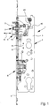
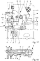
- a mortise lock 1 is shown with a lock housing 2 omitting various components of the lock mechanism.
- the lock housing 2 itself has a lock case 3, which essentially consists of a plate or a sheet metal as a lock bottom, on which or the lock mechanism is constructed. Not shown is also belonging to the lock housing 2 lock cover, which is firmly connected to the closure of the lock housing 2 with the lock case 3.
- a lock plate 4 is provided on the one longitudinal side of the lock housing 3.
- the mortise 1 also has a latch 5 and a latch 6.
- the latch 5 and the latch 6 are coupled to each other in terms of movement, wherein when the latch 5 falls into an external strike plate S of a door frame and provided on the case 5 triggering device 7 is actuated, an automatic self-locking of the bolt 6 takes place, the latch 6 so extends and dips into the strike plate S.
- the triggering device 7 of the case 5 is so coupled to the latch 6 that when driving back the case 5 in the lock housing 2 when interacting with the strike plate S, the triggering device 7 a latch-release lever 8 is actuated, which releases the latch 6, so that Latch 6 then extends out of the lock housing 2 and also engages in the strike plate S. Specifically, this is the comments on the 11 to 18 directed.
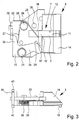
- the triggering device 7 has an axially displaceable strike plate release lever 9 for interacting with the strike plate S and further comprises a toggle lever 10.
- the strike-release lever 9 is in the axial direction A, ie in the direction of movement of the case 5, displaced.
- the axial direction A corresponds in the installed state of the mortise lock 1 of the horizontal direction.
- the axial displacement of the striking plate release lever 9 due to the interaction with the strike plate S causes a pivoting of the articulated lever 10.
- the pivoting of the articulated lever 10 in turn causes a linear adjustment of the latch release lever 8 in the direction B, which is perpendicular to the axial direction A.
- the direction B corresponds to the vertical direction.
- the strike plate release lever 9 has a first lever portion 11 and a second lever portion 12.
- the first lever portion 11 is guided in a guide 13 in the case head 14 of the case 5.
- the guide 13 itself is slot-shaped and has on opposite sides in each case an incised groove 15.
- the grooves 15 are provided for receiving a locking pin 16 which is inserted into the front end of the first lever portion 11.
- a corresponding hole 17 is provided by the locking pin 16 a position-safe arrangement of the strike plate release lever 9 in the case head 14 is ensured.
- the first lever portion 11 at its front end on a protruding nose 18 for cooperation with the striking plate S.
- the second lever portion 12 is arranged at right angles to the first lever portion 11.
- the second lever portion 12 is led out of the case head 14 and is in the maximum extended position of the strike release lever 9 at least substantially on the back 19 of the case head 14 at.
- the second lever portion 12 is provided for cooperation with the articulated lever 10.
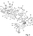
- the articulated lever 10 itself is articulated on the latch holder 20 of the case 5.
- a bearing pin 21 which is passed through an opening 22 of the articulated lever 10 and engages in a corresponding opening 23 in the case holder 20.
- the bearing pin 21 may be riveted to the case holder 20, for example.
- the articulated lever 10 has a first articulated arm 24 with an inclined running surface 25 for interacting with the second lever portion 11 of the striking plate release lever 9. This will be discussed in detail later.
- the striker release lever 9 and the articulated lever 10 are spring-loaded via a common spring element 26.
- the spring element 26 is a leg spring with two spring legs 27, 28.
- the spring element 26 is mounted on the case holder 20 via a bearing pin 29.
- the spring leg 27 of the leg spring acts on an angled from the first articulated arm 24 of the articulated lever 10 second articulated arm 30 and acts on the toggle lever 10 thus away from the latch release lever 8.
- the second spring leg 28 acts on the second lever portion 12 of the strike plate release lever.
- the case head 14 is detachably attachable to the case holder.
- the Trap head 14 formed as a turning trainee head.
- the case head 14 has a central receiving slot 31 for receiving the latch holder 20.
- the central receiving slot 31 is located in the center plane of the case head 14.
- the receiving slot 31 is provided for receiving the front ends of two legs 32, 33 of the latch holder 20. The immersed in the receiving slot 31 ends of the legs 32, 33 are secured by two setscrews 34.
- the second lever portion 12 has two lever arms 36, 37 pointing in opposite directions, each of the lever arms 36, 37 being provided on one side of the latch holder 20.
- the two lever arms 36, 37 arranged in the manner of a step, so that there is a lower-side arrangement of a lever arm and an upper-side arrangement of the other lever arm.
- a lug 38 is provided on the latch holder 20, moreover, which serves to support the spring leg 28 and secures the spring element 26 during disassembly of the case head 14 for turning.
- the case 5 has a latch guide 20 provided on the latch holder 20 on the side opposite the latch head 14, which serves to secure the bearing of the latch 5 in the lock housing 2.
- the trap guide 39 is formed as a plate-shaped element and extends at right angles to the plane of the latch holder 20.
- Upper and lower sides, the latch guide 20 each have a projection 40, 41 on.
- Corresponding guide slots in the lock housing 2 correspond to the projections 40, 41 Fig. 1 a guide slot 42 for the projection 41 is shown in the lock case 3.
- the case 5 is an assembled unit.
- the case head 14 by the measure of 12 mm from the lock plate 4 out.
- the latch 5 itself can assume two end states between which the latch 5 is movable to and fro, namely an open position in which the latch 5 is retracted, and a closed position in which the latch 5 protrudes, as shown in FIG Fig. 1 is shown. It is the latch 5 spring-loaded via a spring element 43, which presses the latch 5 in the closed position.
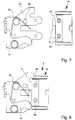
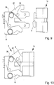
- FIGS. 7 to 10 clarify turning key head function of the case according to the invention 5.
- By loosening the two setscrews 34 it is possible to separate the case head 14 from the case holder 20. A change in the DIN direction is possible by the fitter on site.
- To secure the spring element 26 is used in the removed state of the case head 14 of the mandrel 38, as the FIGS. 7 and 9 illustrate. After rotation of the case head 14 with the strike plate release lever 9, this is again pushed onto the latch shaft 20 and then secured in turn with the two setscrews 34.
Claims (12)
- Serrure encastrée (1) avec un boîtier de serrure (2), un pêne (5) interagissant avec une gâche (S) et un verrou (6), un dispositif de déclenchement (7) interagissant avec la gâche (S) étant prévu sur le pêne (5) et le dispositif de déclenchement (7) étant couplé avec le verrou (6) de façon à ce que, lors de l'interaction du dispositif de déclenchement (7) avec la gâche (S), un levier de déclenchement de verrou (8) est actionné pour libérer le verrou (6) puis pour sortir le verrou (6) du boîtier de serrure (2), le dispositif de déclenchement (7) comprenant un levier de déclenchement de gâche (9) mobile axialement dans la direction du mouvement du pêne (5), destiné à interagir avec la gâche (S), et un levier articulé (10), le levier de déclenchement de gâche (9) provoquant, lors d'un déplacement axial dû à l'interaction avec la gâche (S), un pivotement du levier articulé (10) et le pivotement du levier articulé (10) provoquant un déplacement linéaire du levier de déclenchement de verrou (8) et la sortie du verrou (6), caractérisé en ce que le levier de déclenchement de gâche (9) et le levier articulé (10) sont munis d'un élément de ressort (26) commun.
- Serrure encastrée selon la revendication 1, caractérisée en ce que le levier de déclenchement de gâche (9) comprend une première portion de levier (11), guidée dans un guidage (13) dans la tête (14) du pêne (5), avec un moyeu (18) opposé pour une interaction avec la gâche (S) et une deuxième portion de levier (12), opposée latéralement à la première portion de levier (11), guidée hors de la tête du pêne (14), pour une interaction avec le levier articulé (10).
- Serrure encastrée selon la revendication 2, caractérisée en ce que le levier articulé (10) est logé de manière articulée au niveau d'un support (20) du pêne (5) et comprend un premier bras articulé (24) avec une surface de roulement inclinée (25) pour une interaction avec la deuxième portion de levier (12) du levier de déclenchement de gâche (9).
- Serrure encastrée selon l'une des revendications précédentes, caractérisée en ce que l'élément de ressort (26) est un ressort à branches comprenant deux branches de ressort (27, 28).
- Serrure encastrée selon la revendication 4, caractérisée en ce qu'une branche de ressort (27) agit sur un deux bras articulé (30) du levier articulé (10), plié par rapport au premier bras articulé (24) et/ou l'autre branche de ressort (28) agit sur la deuxième portion de levier (12) du levier de déclenchement de gâche (9).
- Serrure encastrée selon l'une des revendications précédentes, caractérisée en ce que le pêne (5) comprend un support de pêne (20) et une tête de pêne (14) pouvant être reliée de manière amovible avec le support de pêne (20).
- Serrure encastrée selon la revendication 6, caractérisée en ce que la tête de pêne (14) est conçue comme une tête de pêne à renversement.
- Serrure encastrée selon l'une des revendications 6 ou 7, caractérisée en ce que, pour la liaison de la tête de pêne (14) avec le support de pêne (20), une liaison vissée, plus particulièrement par l'intermédiaire de deux tiges filetées (34) est prévue.
- Serrure encastrée selon l'une des revendications 2 à 8, caractérisée en ce que la deuxième portion de levier (12) comprend deux bras de levier (36, 37) orientés dans des directions opposées.
- Serrure encastrée selon la revendication 9, caractérisée en ce que chacun des bras de levier (36, 37) est prévu sur un côté du support de pêne (20).
- Serrure encastrée selon l'une des revendications 6 à 10, caractérisée en ce que, sur le support de pêne (20), est prévue une saillie, plus particulièrement sous la forme d'une tige rapportée (38), pour l'appui de l'autre branche de ressort (28) pour le démontage de la tête de pêne (14).
- Serrure encastrée selon l'une des revendications 6 à 10, caractérisée en ce que, sur le support de pêne (20), sur le côté opposé à la tête de pêne (14), est prévu un guidage de pêne (39) pour le logement du pêne (5) dans le boîtier de serrure (2).
Priority Applications (1)
| Application Number | Priority Date | Filing Date | Title |
|---|---|---|---|
| PL13004870T PL2719850T3 (pl) | 2012-10-15 | 2013-10-10 | Zamek wpuszczany |
Applications Claiming Priority (1)
| Application Number | Priority Date | Filing Date | Title |
|---|---|---|---|
| DE102012020139.7A DE102012020139A1 (de) | 2012-10-15 | 2012-10-15 | Einsteckschloss |
Publications (3)
| Publication Number | Publication Date |
|---|---|
| EP2719850A2 EP2719850A2 (fr) | 2014-04-16 |
| EP2719850A3 EP2719850A3 (fr) | 2015-07-22 |
| EP2719850B1 true EP2719850B1 (fr) | 2017-08-09 |
Family
ID=49354424
Family Applications (1)
| Application Number | Title | Priority Date | Filing Date |
|---|---|---|---|
| EP13004870.5A Active EP2719850B1 (fr) | 2012-10-15 | 2013-10-10 | Serrure à mortaiser |
Country Status (3)
| Country | Link |
|---|---|
| EP (1) | EP2719850B1 (fr) |
| DE (1) | DE102012020139A1 (fr) |
| PL (1) | PL2719850T3 (fr) |
Families Citing this family (1)
| Publication number | Priority date | Publication date | Assignee | Title |
|---|---|---|---|---|
| AT515799B1 (de) * | 2014-03-31 | 2015-12-15 | Roto Frank Ag | Schloss |
Family Cites Families (6)
| Publication number | Priority date | Publication date | Assignee | Title |
|---|---|---|---|---|
| DE289120C (fr) * | ||||
| DE90300C (fr) * | ||||
| DE614907C (de) * | 1932-03-23 | 1935-06-21 | Welwyn Lock & Fittings Co Ltd | Tuerschloss mit selbsttaetiger Ausloesung der den Riegel in Offenstellung festhaltenden Sperrung |
| DE19749023B4 (de) * | 1997-11-06 | 2004-03-25 | Wilka Schließtechnik GmbH | Schloß für Türen, Fenster oder dergleichen |
| DE29812665U1 (de) * | 1998-07-16 | 1998-12-24 | Saechsische Schlosfabrik Pegau | Selbstverriegelndes Schloß |
| DE202011001842U1 (de) * | 2011-01-14 | 2011-04-21 | Bks Gmbh | Verriegelungseinrichtung |
-
2012
- 2012-10-15 DE DE102012020139.7A patent/DE102012020139A1/de not_active Ceased
-
2013
- 2013-10-10 EP EP13004870.5A patent/EP2719850B1/fr active Active
- 2013-10-10 PL PL13004870T patent/PL2719850T3/pl unknown
Non-Patent Citations (1)
| Title |
|---|
| None * |
Also Published As
| Publication number | Publication date |
|---|---|
| PL2719850T3 (pl) | 2018-01-31 |
| DE102012020139A1 (de) | 2014-04-17 |
| EP2719850A2 (fr) | 2014-04-16 |
| EP2719850A3 (fr) | 2015-07-22 |
Similar Documents
| Publication | Publication Date | Title |
|---|---|---|
| EP2193246B1 (fr) | Paire de poignées de commande de porte | |
| EP0911470A2 (fr) | Dispositif de verrouillage | |
| EP0610542B1 (fr) | Serrure mortaisée en particulier pour portes d'appartement, notamment serrure avec barres coulissantes | |
| EP0954667B1 (fr) | Serrure a pene demi-tour pour porte ou fenetre | |
| DE19858174C2 (de) | Türschloß | |
| EP1477625B1 (fr) | Serrure de porte pour verrou lustre | |
| DE202012009802U1 (de) | Einsteckschloss | |
| DE3334298C3 (de) | Verschluß für Fenster, Türen oder dergleichen | |
| EP2719850B1 (fr) | Serrure à mortaiser | |
| EP3371397B1 (fr) | Ensemble ferrure | |
| DE202015000208U1 (de) | Schloss zur Betätigung wenigstens einer Treibstange | |
| DE19815671B4 (de) | Treibstangenverschluß | |
| EP0828047B1 (fr) | Serrure à pêne demi-tour | |
| EP0592012B1 (fr) | Crémone | |
| EP3745921B1 (fr) | Dispositif de fixation pour un panneau d'un tiroir | |
| EP3655601B1 (fr) | Serrure | |
| DE19628011C2 (de) | Spereinrichtung für die Riegel eine Riegelwerks | |
| EP2453086B1 (fr) | Ferrure de crémone pour battant fixe de fenêtres ou de portes à deux vantaux sans montant médian | |
| AT509464B1 (de) | Schloss | |
| DE102014207110B4 (de) | Fallenschloss | |
| DE202005013426U1 (de) | Fehlbedienungssicherung | |
| EP2085543B1 (fr) | Serrure | |
| EP0581326A1 (fr) | Système de bielle motrice | |
| DE19828365C1 (de) | Schloß für schall- und/oder wärmedämmende Türen | |
| EP0298292A2 (fr) | Serrure de porte à pêne et demi-tour coulissants |
Legal Events
| Date | Code | Title | Description |
|---|---|---|---|
| PUAI | Public reference made under article 153(3) epc to a published international application that has entered the european phase |
Free format text: ORIGINAL CODE: 0009012 |
|
| AK | Designated contracting states |
Kind code of ref document: A2 Designated state(s): AL AT BE BG CH CY CZ DE DK EE ES FI FR GB GR HR HU IE IS IT LI LT LU LV MC MK MT NL NO PL PT RO RS SE SI SK SM TR |
|
| AX | Request for extension of the european patent |
Extension state: BA ME |
|
| PUAL | Search report despatched |
Free format text: ORIGINAL CODE: 0009013 |
|
| AK | Designated contracting states |
Kind code of ref document: A3 Designated state(s): AL AT BE BG CH CY CZ DE DK EE ES FI FR GB GR HR HU IE IS IT LI LT LU LV MC MK MT NL NO PL PT RO RS SE SI SK SM TR |
|
| AX | Request for extension of the european patent |
Extension state: BA ME |
|
| RIC1 | Information provided on ipc code assigned before grant |
Ipc: E05B 63/20 20060101AFI20150615BHEP Ipc: E05B 15/10 20060101ALI20150615BHEP Ipc: E05B 63/04 20060101ALI20150615BHEP Ipc: E05B 59/00 20060101ALI20150615BHEP |
|
| 17P | Request for examination filed |
Effective date: 20150903 |
|
| RBV | Designated contracting states (corrected) |
Designated state(s): AL AT BE BG CH CY CZ DE DK EE ES FI FR GB GR HR HU IE IS IT LI LT LU LV MC MK MT NL NO PL PT RO RS SE SI SK SM TR |
|
| GRAP | Despatch of communication of intention to grant a patent |
Free format text: ORIGINAL CODE: EPIDOSNIGR1 |
|
| RIC1 | Information provided on ipc code assigned before grant |
Ipc: E05B 59/00 20060101ALI20170515BHEP Ipc: E05B 15/10 20060101ALI20170515BHEP Ipc: E05B 63/20 20060101AFI20170515BHEP Ipc: E05B 63/04 20060101ALI20170515BHEP |
|
| GRAS | Grant fee paid |
Free format text: ORIGINAL CODE: EPIDOSNIGR3 |
|
| INTG | Intention to grant announced |
Effective date: 20170606 |
|
| GRAA | (expected) grant |
Free format text: ORIGINAL CODE: 0009210 |
|
| AK | Designated contracting states |
Kind code of ref document: B1 Designated state(s): AL AT BE BG CH CY CZ DE DK EE ES FI FR GB GR HR HU IE IS IT LI LT LU LV MC MK MT NL NO PL PT RO RS SE SI SK SM TR |
|
| REG | Reference to a national code |
Ref country code: GB Ref legal event code: FG4D Free format text: NOT ENGLISH |
|
| REG | Reference to a national code |
Ref country code: CH Ref legal event code: EP Ref country code: AT Ref legal event code: REF Ref document number: 917039 Country of ref document: AT Kind code of ref document: T Effective date: 20170815 |
|
| REG | Reference to a national code |
Ref country code: IE Ref legal event code: FG4D Free format text: LANGUAGE OF EP DOCUMENT: GERMAN |
|
| REG | Reference to a national code |
Ref country code: DE Ref legal event code: R096 Ref document number: 502013007972 Country of ref document: DE |
|
| REG | Reference to a national code |
Ref country code: FR Ref legal event code: PLFP Year of fee payment: 5 |
|
| REG | Reference to a national code |
Ref country code: NL Ref legal event code: MP Effective date: 20170809 |
|
| REG | Reference to a national code |
Ref country code: LT Ref legal event code: MG4D |
|
| PG25 | Lapsed in a contracting state [announced via postgrant information from national office to epo] |
Ref country code: LT Free format text: LAPSE BECAUSE OF FAILURE TO SUBMIT A TRANSLATION OF THE DESCRIPTION OR TO PAY THE FEE WITHIN THE PRESCRIBED TIME-LIMIT Effective date: 20170809 Ref country code: FI Free format text: LAPSE BECAUSE OF FAILURE TO SUBMIT A TRANSLATION OF THE DESCRIPTION OR TO PAY THE FEE WITHIN THE PRESCRIBED TIME-LIMIT Effective date: 20170809 Ref country code: SE Free format text: LAPSE BECAUSE OF FAILURE TO SUBMIT A TRANSLATION OF THE DESCRIPTION OR TO PAY THE FEE WITHIN THE PRESCRIBED TIME-LIMIT Effective date: 20170809 Ref country code: NO Free format text: LAPSE BECAUSE OF FAILURE TO SUBMIT A TRANSLATION OF THE DESCRIPTION OR TO PAY THE FEE WITHIN THE PRESCRIBED TIME-LIMIT Effective date: 20171109 Ref country code: HR Free format text: LAPSE BECAUSE OF FAILURE TO SUBMIT A TRANSLATION OF THE DESCRIPTION OR TO PAY THE FEE WITHIN THE PRESCRIBED TIME-LIMIT Effective date: 20170809 Ref country code: NL Free format text: LAPSE BECAUSE OF FAILURE TO SUBMIT A TRANSLATION OF THE DESCRIPTION OR TO PAY THE FEE WITHIN THE PRESCRIBED TIME-LIMIT Effective date: 20170809 |
|
| PG25 | Lapsed in a contracting state [announced via postgrant information from national office to epo] |
Ref country code: BG Free format text: LAPSE BECAUSE OF FAILURE TO SUBMIT A TRANSLATION OF THE DESCRIPTION OR TO PAY THE FEE WITHIN THE PRESCRIBED TIME-LIMIT Effective date: 20171109 Ref country code: RS Free format text: LAPSE BECAUSE OF FAILURE TO SUBMIT A TRANSLATION OF THE DESCRIPTION OR TO PAY THE FEE WITHIN THE PRESCRIBED TIME-LIMIT Effective date: 20170809 Ref country code: ES Free format text: LAPSE BECAUSE OF FAILURE TO SUBMIT A TRANSLATION OF THE DESCRIPTION OR TO PAY THE FEE WITHIN THE PRESCRIBED TIME-LIMIT Effective date: 20170809 Ref country code: GR Free format text: LAPSE BECAUSE OF FAILURE TO SUBMIT A TRANSLATION OF THE DESCRIPTION OR TO PAY THE FEE WITHIN THE PRESCRIBED TIME-LIMIT Effective date: 20171110 Ref country code: IS Free format text: LAPSE BECAUSE OF FAILURE TO SUBMIT A TRANSLATION OF THE DESCRIPTION OR TO PAY THE FEE WITHIN THE PRESCRIBED TIME-LIMIT Effective date: 20171209 Ref country code: LV Free format text: LAPSE BECAUSE OF FAILURE TO SUBMIT A TRANSLATION OF THE DESCRIPTION OR TO PAY THE FEE WITHIN THE PRESCRIBED TIME-LIMIT Effective date: 20170809 |
|
| PG25 | Lapsed in a contracting state [announced via postgrant information from national office to epo] |
Ref country code: CZ Free format text: LAPSE BECAUSE OF FAILURE TO SUBMIT A TRANSLATION OF THE DESCRIPTION OR TO PAY THE FEE WITHIN THE PRESCRIBED TIME-LIMIT Effective date: 20170809 Ref country code: DK Free format text: LAPSE BECAUSE OF FAILURE TO SUBMIT A TRANSLATION OF THE DESCRIPTION OR TO PAY THE FEE WITHIN THE PRESCRIBED TIME-LIMIT Effective date: 20170809 Ref country code: RO Free format text: LAPSE BECAUSE OF FAILURE TO SUBMIT A TRANSLATION OF THE DESCRIPTION OR TO PAY THE FEE WITHIN THE PRESCRIBED TIME-LIMIT Effective date: 20170809 |
|
| REG | Reference to a national code |
Ref country code: DE Ref legal event code: R097 Ref document number: 502013007972 Country of ref document: DE |
|
| PG25 | Lapsed in a contracting state [announced via postgrant information from national office to epo] |
Ref country code: SM Free format text: LAPSE BECAUSE OF FAILURE TO SUBMIT A TRANSLATION OF THE DESCRIPTION OR TO PAY THE FEE WITHIN THE PRESCRIBED TIME-LIMIT Effective date: 20170809 Ref country code: MC Free format text: LAPSE BECAUSE OF FAILURE TO SUBMIT A TRANSLATION OF THE DESCRIPTION OR TO PAY THE FEE WITHIN THE PRESCRIBED TIME-LIMIT Effective date: 20170809 Ref country code: SK Free format text: LAPSE BECAUSE OF FAILURE TO SUBMIT A TRANSLATION OF THE DESCRIPTION OR TO PAY THE FEE WITHIN THE PRESCRIBED TIME-LIMIT Effective date: 20170809 Ref country code: IT Free format text: LAPSE BECAUSE OF FAILURE TO SUBMIT A TRANSLATION OF THE DESCRIPTION OR TO PAY THE FEE WITHIN THE PRESCRIBED TIME-LIMIT Effective date: 20170809 Ref country code: EE Free format text: LAPSE BECAUSE OF FAILURE TO SUBMIT A TRANSLATION OF THE DESCRIPTION OR TO PAY THE FEE WITHIN THE PRESCRIBED TIME-LIMIT Effective date: 20170809 |
|
| PLBE | No opposition filed within time limit |
Free format text: ORIGINAL CODE: 0009261 |
|
| STAA | Information on the status of an ep patent application or granted ep patent |
Free format text: STATUS: NO OPPOSITION FILED WITHIN TIME LIMIT |
|
| 26N | No opposition filed |
Effective date: 20180511 |
|
| GBPC | Gb: european patent ceased through non-payment of renewal fee |
Effective date: 20171109 |
|
| REG | Reference to a national code |
Ref country code: IE Ref legal event code: MM4A |
|
| PG25 | Lapsed in a contracting state [announced via postgrant information from national office to epo] |
Ref country code: LU Free format text: LAPSE BECAUSE OF NON-PAYMENT OF DUE FEES Effective date: 20171010 |
|
| PG25 | Lapsed in a contracting state [announced via postgrant information from national office to epo] |
Ref country code: SI Free format text: LAPSE BECAUSE OF FAILURE TO SUBMIT A TRANSLATION OF THE DESCRIPTION OR TO PAY THE FEE WITHIN THE PRESCRIBED TIME-LIMIT Effective date: 20170809 |
|
| PG25 | Lapsed in a contracting state [announced via postgrant information from national office to epo] |
Ref country code: MT Free format text: LAPSE BECAUSE OF FAILURE TO SUBMIT A TRANSLATION OF THE DESCRIPTION OR TO PAY THE FEE WITHIN THE PRESCRIBED TIME-LIMIT Effective date: 20170809 |
|
| REG | Reference to a national code |
Ref country code: FR Ref legal event code: PLFP Year of fee payment: 6 |
|
| PG25 | Lapsed in a contracting state [announced via postgrant information from national office to epo] |
Ref country code: IE Free format text: LAPSE BECAUSE OF NON-PAYMENT OF DUE FEES Effective date: 20171010 |
|
| PG25 | Lapsed in a contracting state [announced via postgrant information from national office to epo] |
Ref country code: GB Free format text: LAPSE BECAUSE OF NON-PAYMENT OF DUE FEES Effective date: 20171109 |
|
| PG25 | Lapsed in a contracting state [announced via postgrant information from national office to epo] |
Ref country code: HU Free format text: LAPSE BECAUSE OF FAILURE TO SUBMIT A TRANSLATION OF THE DESCRIPTION OR TO PAY THE FEE WITHIN THE PRESCRIBED TIME-LIMIT; INVALID AB INITIO Effective date: 20131010 |
|
| PG25 | Lapsed in a contracting state [announced via postgrant information from national office to epo] |
Ref country code: CY Free format text: LAPSE BECAUSE OF NON-PAYMENT OF DUE FEES Effective date: 20170809 |
|
| PG25 | Lapsed in a contracting state [announced via postgrant information from national office to epo] |
Ref country code: MK Free format text: LAPSE BECAUSE OF FAILURE TO SUBMIT A TRANSLATION OF THE DESCRIPTION OR TO PAY THE FEE WITHIN THE PRESCRIBED TIME-LIMIT Effective date: 20170809 |
|
| PG25 | Lapsed in a contracting state [announced via postgrant information from national office to epo] |
Ref country code: TR Free format text: LAPSE BECAUSE OF FAILURE TO SUBMIT A TRANSLATION OF THE DESCRIPTION OR TO PAY THE FEE WITHIN THE PRESCRIBED TIME-LIMIT Effective date: 20170809 |
|
| PG25 | Lapsed in a contracting state [announced via postgrant information from national office to epo] |
Ref country code: PT Free format text: LAPSE BECAUSE OF FAILURE TO SUBMIT A TRANSLATION OF THE DESCRIPTION OR TO PAY THE FEE WITHIN THE PRESCRIBED TIME-LIMIT Effective date: 20170809 |
|
| PG25 | Lapsed in a contracting state [announced via postgrant information from national office to epo] |
Ref country code: AL Free format text: LAPSE BECAUSE OF FAILURE TO SUBMIT A TRANSLATION OF THE DESCRIPTION OR TO PAY THE FEE WITHIN THE PRESCRIBED TIME-LIMIT Effective date: 20170809 |
|
| P01 | Opt-out of the competence of the unified patent court (upc) registered |
Effective date: 20230613 |
|
| PGFP | Annual fee paid to national office [announced via postgrant information from national office to epo] |
Ref country code: PL Payment date: 20230928 Year of fee payment: 11 |
|
| PGFP | Annual fee paid to national office [announced via postgrant information from national office to epo] |
Ref country code: FR Payment date: 20231025 Year of fee payment: 11 Ref country code: DE Payment date: 20231016 Year of fee payment: 11 Ref country code: CH Payment date: 20231102 Year of fee payment: 11 Ref country code: AT Payment date: 20231020 Year of fee payment: 11 |
|
| PGFP | Annual fee paid to national office [announced via postgrant information from national office to epo] |
Ref country code: BE Payment date: 20231019 Year of fee payment: 11 |