EP2719557A1 - Aktiver stabilisator - Google Patents
Aktiver stabilisator Download PDFInfo
- Publication number
- EP2719557A1 EP2719557A1 EP12382392.4A EP12382392A EP2719557A1 EP 2719557 A1 EP2719557 A1 EP 2719557A1 EP 12382392 A EP12382392 A EP 12382392A EP 2719557 A1 EP2719557 A1 EP 2719557A1
- Authority
- EP
- European Patent Office
- Prior art keywords
- stabilizer bar
- support
- central part
- roll device
- bar
- Prior art date
- Legal status (The legal status is an assumption and is not a legal conclusion. Google has not performed a legal analysis and makes no representation as to the accuracy of the status listed.)
- Withdrawn
Links
Images


Classifications
-
- B—PERFORMING OPERATIONS; TRANSPORTING
- B60—VEHICLES IN GENERAL
- B60G—VEHICLE SUSPENSION ARRANGEMENTS
- B60G21/00—Interconnection systems for two or more resiliently-suspended wheels, e.g. for stabilising a vehicle body with respect to acceleration, deceleration or centrifugal forces
- B60G21/02—Interconnection systems for two or more resiliently-suspended wheels, e.g. for stabilising a vehicle body with respect to acceleration, deceleration or centrifugal forces permanently interconnected
- B60G21/04—Interconnection systems for two or more resiliently-suspended wheels, e.g. for stabilising a vehicle body with respect to acceleration, deceleration or centrifugal forces permanently interconnected mechanically
- B60G21/05—Interconnection systems for two or more resiliently-suspended wheels, e.g. for stabilising a vehicle body with respect to acceleration, deceleration or centrifugal forces permanently interconnected mechanically between wheels on the same axle but on different sides of the vehicle, i.e. the left and right wheel suspensions being interconnected
- B60G21/055—Stabiliser bars
- B60G21/0551—Mounting means therefor
- B60G21/0553—Mounting means therefor adjustable
-
- B—PERFORMING OPERATIONS; TRANSPORTING
- B60—VEHICLES IN GENERAL
- B60G—VEHICLE SUSPENSION ARRANGEMENTS
- B60G2204/00—Indexing codes related to suspensions per se or to auxiliary parts
- B60G2204/10—Mounting of suspension elements
- B60G2204/12—Mounting of springs or dampers
- B60G2204/122—Mounting of torsion springs
- B60G2204/1222—Middle mounts of stabiliser on vehicle body or chassis
Definitions
- the present invention has an application in the automotive industry, and more specifically in the field of suspension systems.
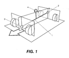
- roll is defined as the rotation experienced by the sprung mass around the roll axis (1) of the vehicle caused by centrifugal force.
- the roll axis (1) is defined by an imaginary line joining the rear roll center (2) and the front roll center (3), where said centers (2, 3) are defined by the geometry of the automotive vehicle suspension in each case.
- the center of gravity (4) of the vehicle is in turn located above the roll axis (1), this characteristic being what generates roll when the vehicle is traveling on a curve due to the effect of centrifugal force, which affects the lateral stability of the vehicle.
- the vehicle roll phenomenon can be reduced by means of stiffening the suspension, with the drawback that comfort is decreased.
- Completely eliminating vehicle roll also has drawbacks, because said roll gives the driver the feeling of being alert when entering a curve at a high speed, which results in the driver reducing the speed, such that it is a safety measure for driving the automotive vehicle.
- the suspension incorporates an anti-roll system comprising a stabilizer or torsion bar (5), as can be seen in Figures 2 , 3 , 4 and 12 .
- the stabilizer bar (5) is attached in its central part (8), which is straight, to the front cradle (12) of the vehicle, generally by means of supports (13) which allow the stabilizer bar (5) to rotate with respect to the cradle (12).
- Said supports (13) are usually elastic supports to prevent blows and abrupt movements or vibrations from being transmitted to the interior of the vehicle.
- the stabilizer bar (5) is connected at its ends to connection bars (14), usually referred to as stabilizer links, by means of the articulation thereof at the connection points (9).
- connection bars (14) are in turn connected, also by means of articulation, to a shock absorber (15) of the vehicle suspension at its opposite end, all this seen in Figure 2 .
- the stiffness of an automotive vehicle depends on the entire kinematic chain forming the actual vehicle suspension, such as for example the shock absorber, suspension spring, articulations between different moving components, the actual stiffness of the frame, etc.
- the element having the greatest effect on vehicle roll is the stabilizer bar.
- the increase in the stiffness of the stabilizer bar (5) primarily depends on two main characteristics; on one hand it depends on the geometry of the actual stabilizer bar (5) and on the other hand on the mechanical characteristics of the material of the stabilizer bar (5).
- the geometric characteristics affecting the stiffness of the stabilizer bar (5) are the length between supports (13), which defines the central part (8), also referred to as the active part, the length of the lever arms (6), which is a curved part that can have different configurations, the length of the cantilever part (7) and the geometry of the cross-section of the stabilizer bar (5) in each segment (6, 7, 8).
- the stabilizer bar (5) works by torsion and bending.
- the predominant force is one or the other depending on which part of the stabilizer bar (5) is analyzed.
- three geometric areas can be distinguished, consisting of the areas corresponding to the ends, which are the lever arms (6), the central part (8) located between the two supports (13), and the cantilever parts (7) which are the prolongation of the central part (8) beyond the supports (13).
- the predominant stress in the central part (8) of the stabilizer bar (5) is torsional stress, and depending on the stiffness of the supports, a bending stress occurs to a greater or lesser degree, such that if the supports are elastic supports, the effect of the bending is greater the less stiff the supports are, and in contrast, if the supports are stiff supports, bending stress in the central part (8) is less, being able to be nil.
- the operation of the anti-roll system described above is as follows: when the automotive vehicle enters a curve, the torsion or stabilizer bar (5) exerts a moment opposite the roll moment of the vehicle, such that it stabilizes the vehicle. Said moment exerted by the stabilizer bar (5) is produced by the reaction to the forces exerted during vehicle roll. The magnitude of the reaction is determined by the geometry and by the material of the stabilizer bar (5). Stabilizer bars (5) used in conventional vehicles today have constant geometry and materials while driving the automotive vehicle, so the force which the stabilizer bar (5) can exert depends only on the degree of roll of the automotive vehicle, such that the greater the roll, the greater the reaction of the stabilizer bar (5). These anti-roll systems have a significant limitation consisting of the impossibility of varying or modifying the stiffness of the torsion bar (5) while driving the vehicle.
- the hydraulic motor when it is active, i.e., when it acts, it exerts the necessary force to connect or join the two half-bars, thus forming a single stiff bar, this being the preferred mode for example when the automotive vehicle traveling on a road enters a curve.
- this mechanism has a split stabilizer bar, i.e., it can have a roll stiffness of nil value.
- the stabilizer bar does not transmit forces from one end to the other because there is no connection between both ends and because the clutch is attached to the frame, and secondly the stabilizer bar loses the capability of working as a torsion spring.
- the stabilizer bar loses the capability of working as a torsion spring.
- the stabilizer bar when a continuous bar is twisted, it accumulates energy that it is capable of returning as soon as the load causing its torsion is no longer being applied, such that the bar returns to its nominal position.
- this property or capability is lost.
- this active mechanism has the drawback that it causes high friction generated by the contact between a projection and a groove comprised in the device for acting on the spring, such that said projection experiences considerable wear, resulting in the occurrence of unwanted allowances, with the noises and impacts they entail.
- This device uses two motors which are arranged on the lever arm of the stabilizer bar, i.e., in motion with it, which creates greater inertia for the bar.
- the variation of stiffness is not that broad because the bar must always conserve a minimum section so that it does not break and a maximum section established by the available space, so the variation of stiffness can only be between a minimum stiffness value and a maximum stiffness value that are very close to one another.
- the variation of stiffness is determined by the bending of the lever arm; however, it must be considered that the length of the lever arm of a conventional stabilizer bar is not very long, so the variation of stiffness achieved by means of this device is not really noticeable for driving. Furthermore, depending on the configuration of the fixing of the ball and socket joint used at the end of the lever arm, a very large working space for the ball and socket joint may be required given that it has to make a very wide rotation, which entails a design limitation and drawback.
- a first aspect of the present invention relates to an active anti-roll device for automotive vehicles, which allows achieving equilibrium in the stiffness of the suspension to achieve optimal adaptation to both driving on a road and to driving on irregular terrains, maintaining a compromise between safety and comfort, all in an economical and simple manner.
- the device proposed by the invention comprises a stabilizer bar, also usually referred to as a torsion bar, where said stabilizer bar in turn comprises a straight central part, also referred to as the active part because it is the part working mostly under torsion, which is articulated in at least two supports which can be elastic or completely stiff, attached to a front cradle or to the frame of an automotive vehicle suspension.
- a stabilizer bar also usually referred to as a torsion bar
- said stabilizer bar in turn comprises a straight central part, also referred to as the active part because it is the part working mostly under torsion, which is articulated in at least two supports which can be elastic or completely stiff, attached to a front cradle or to the frame of an automotive vehicle suspension.
- each lever arm is in turn connected at its end with a connection bar, also usually referred to as stabilizer link, by means of the articulation thereof, such that at the opposite end each connection bar is connected with the wheel of the vehicle, by means of the articulation thereof, through an intermediate element capable of transmitting the reaction forces of the stabilizer bar to the wheels, i.e., through the interconnection of at least another part, for example the arm of the suspension or the shock absorber of the automotive vehicle suspension.
- a connection bar also usually referred to as stabilizer link
- the active anti-roll device comprises means for modifying or varying the bending stress generated in the stabilizer bar while driving both in the central part and in the cantilever part of the stabilizer bar.
- the device of the invention thus allows modifying or varying the stiffness of the stabilizer bar so that it adapts to different driving modes. For example, if sport driving is desired, the stiffness of the stabilizer bar should be high; however, when traveling on rural and irregular terrain, stiffness of the stabilizer bar should be small, i.e., reduced.
- the solution proposed by the invention is much simpler than the anti-roll systems of the state of the art because it consists of applying the concept of modifying or varying the bending stress, which can be done, for example, by varying the position of the supports of the stabilizer bar.
- said at least two supports can be moved according to a direction coinciding with the direction of the actual central part of the stabilizer bar, such that the length of the central part of the stabilizer bar can be varied by means of said movement, which thereby allows varying the stiffness of the stabilizer bar as a function of the position of the supports, according to the needs present while driving the automotive vehicle.
- a torque or torsional moment is generated which has a direction opposite the torsional moment to which the stabilizer bar is subjected as the result of the actions it receives during conventional operation, i.e., of the actions it receives from the connection bars which are connected to an intermediate element transmitting the reaction forces of the stabilizer bar to the wheels, said intermediate elements in the depicted embodiment being shock absorbers. Stiffness of the stabilizer bar is thereby increased.
- stiffness of the torsion bar should be high to increase the lateral dynamics of the vehicle; however, for driving on rough terrain or in the mountains, stiffness of the stabilizer bar should be small, i.e. reduced.
- Figure 12 depicts a bending moment diagram in a stabilizer bar according to the state of the art.
- ⁇ A F ⁇ L cantilever 2 ⁇ 2 ⁇ L + F ⁇ L cantilever 2 3 ⁇ E ⁇ I - F ⁇ ⁇ L cantilever 2 ⁇ 2 ⁇ L 6 ⁇ E ⁇ I - ESCM ⁇ 2 ⁇ L ⁇ L cantilever 3 ⁇ E ⁇ I + ESCMF ⁇ ⁇ 2 ⁇ L ⁇ L cantilever 6 ⁇ E ⁇ I
- Figure 4 depicts a torsional moment diagram in a stabilizer bar according to the state of the art.
- the turned torsional angle depends on a plurality of variables: on the geometry of the bar, including the lever arm length, the cantilever part length, the total length of the stabilizer bar and the cross-section of the stabilizer bar; said turned torsional angle also depends on the material of the bar, on the type of support of the bar, whether it is elastic to a certain degree or completely stiff, and on the force applied in the lever arms.
- stiffness of the stabilizer bar is constant because its geometry, material and the type of supports are also constant.
- the stabilizer bar works in two ways, one way is by torsion and the other by bending. Solutions which act only on the torque to achieve an active stabilizer bar are already known in the current state of the art. However, the solution proposed by the invention allows attenuating or maximizing, as needed for driving, the effect of bending on the stabilizer bar, achieving a variation of stiffness of the stabilizer bar and therefore achieving an active stabilizer bar.
- the cantilever part of the stabilizer bar increases and therefore less force is necessary for generating that deflection according to the deflection formulation. Since less force is necessary, the torsional rotation generated by said force is also less according to the turned angle formulation. As a result, the torsional moment transmitted by the stabilizer bar is less, i.e., stiffness of said stabilizer bar is reduced.
- the cantilever part of the stabilizer bar decreases and therefore greater force is necessary for generating that deflection according to the deflection formulation. Since greater force is necessary, the torsional rotation generated by said force is also greater according to the turned angle formulation. As a result, the torsional moment transmitted by the stabilizer bar is greater, i.e., stiffness of said stabilizer bar is increased.
- a second aspect of the invention relates to an automotive vehicle comprising an active anti-roll device such as that described above.
- a third aspect of the invention relates to a method for modifying the behavior of an automotive vehicle suspension with respect to roll. To that end, the method comprises modifying the bending and torsional stresses of a stabilizer bar while driving an automotive vehicle.
- the anti-roll device can thus be adjusted for sport driving, in which the torsional stiffness of the bar has to be high, arranging the supports at a maximum separation, or it can be adjusted for driving on rural and irregular terrain, in which the stiffness of the stabilizer bar has to be small, arranging the supports at a minimum separation.
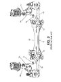
- the active anti-roll device proposed by the invention comprises a stabilizer bar (5) comprising a central part (8) which is articulated in two supports (13) to a cradle (12) or to the frame of the automotive vehicle, said cradle (12) also being connected with the arms of the suspension (10).
- the central part (8) prolongs beyond each support (13) in a cantilever part (7), which is shorter than the central part (8), each cantilever part (7) being bent into a lever arm (6) with an intermediate bend.
- Each lever arm (6) is in turn connected at its end, at a connection point (9), with a connection bar (14) which in turn connects with another intermediate element, a shock absorber (15) of the suspension in the depicted embodiment, and said intermediate element in turn connects with a wheel of the automotive vehicle.
- the active anti-roll device comprises means for modifying or varying the bending and torsional stress generated in the stabilizer bar (5) while driving.
- the modification or variation of the bending and torsional stress is performed by varying the position of the supports (13) of the stabilizer bar (5).
- the two supports (13) can be moved according to a direction coinciding with the direction of the actual central part (8) of the stabilizer bar (5), such that the length of the central part (8) of the stabilizer bar (5) can be varied by means of said movement, which thereby allows varying the stiffness of the stabilizer bar (5) as a function of the position of the supports (13), according to the needs present while driving the automotive vehicle.
- each support (13) being fixed on a motorized linear guide (16), also referred to as linear translational stage or element, which is operated by at least one centrally arranged motor (22), such that each motorized linear guide (16) has a coupling to the motor (25). Achieving the movement of the supports (13) is therefore done by means of a linear movement element.
- a motorized linear guide (16) also referred to as linear translational stage or element, which is operated by at least one centrally arranged motor (22), such that each motorized linear guide (16) has a coupling to the motor (25).
- each support (13) is fixed on a runner (24) the position of which can be fixed with respect to a linear guide (23), also referred to as a translational element or track, on which said runner (24) can slide, for example in a manner controlled by means of a drive device (22) coupled to a spindle (26).
- a linear guide also referred to as a translational element or track
- said linear guides (16, 23) are supported by a support element (11) which is fixed to the cradle (2) or to the frame of the automotive vehicle.
- said linear guide (23) is integrally attached to the cradle (12) of the vehicle and the runner (24) is integrally attached to the support (13), such that the assembly formed by runner (24) and support (13) can be moved along the linear guide (23), which is arranged such that the longitudinal axis of the linear guide (23) is parallel to the longitudinal axis of the central part (8) of the stabilizer bar (5), i.e., to the actual axis of said central part (8).
- each linear guide (16, 23) and the support element (11) there is an elastic element (21) between each linear guide (16, 23) and the support element (11) to absorb vibrations during the operation of the device and to prevent their transmission to the interior of the automotive vehicle.
- Each support (13) also comprises a spherical bearing (17), also referred to as a ball and socket joint, which in turn comprises a fixed part (17') which is integral with the linear guide (16, 23) and a moving part (17") which can rotate with respect to the fixed part (17'), giving each support a spherical degree of freedom.
- Each support (13) in turn comprises a sliding bushing (18), also referred to as a translational joint since it gives each support (13) a translational degree of freedom, located inside the moving part (17") of the spherical bearing (17), where said sliding bushing (18) allows the movement of the stabilizer bar (5) with respect to the support (13).
- a bushing (19) on which the sliding bushing (18) slides is arranged between the stabilizer bar (5) and said sliding bushing (18).
- the supports are mostly elastic supports in the current state of the art, however special supports such as those described have to be used for the device of the invention because the support (13) must be allowed to slide along the stabilizer bar (5), and the cardinal rotation made in the supports (13) due to the bending of the central part (8) must additionally be allowed.
- the invention proposes a stiff support (13) which is a spherical rolling bearing and at the same time allows translation on the outside of the stabilizer bar (5). Since it is completely stiff it transmits vibrations to the frame of the vehicle, generating uncomfortable driving and being able to generate noises. To prevent this, the elastic element (21) is placed between the linear guides (16, 23) and the cradle (12) of the vehicle.
- the anti-roll device of the invention also comprises at least one intermediate, preferably elastic, fixed support (20) arranged on the support element (11) on which the stabilizer bar (5) rests such that it prevents its movement, i.e., its translational movement, according to the direction of the central part (8) of the stabilizer bar (5). If it were not for said intermediate fixed support (20), the stabilizer bar (5) would have a longitudinal degree of freedom. This degree of freedom is eliminated by means of placing the intermediate fixed support (20) joining the stabilizer bar (5) and the cradle (12) or sub-frame of the vehicle, which prevents the longitudinal movement of the bar (5) with respect to the cradle (12).
- the intermediate fixed support (20) is preferably arranged in the center of the stabilizer bar (5) so that it affects neither torsion nor bending in the central part (8) of the stabilizer bar (5).
Priority Applications (1)
| Application Number | Priority Date | Filing Date | Title |
|---|---|---|---|
| EP12382392.4A EP2719557A1 (de) | 2012-10-11 | 2012-10-11 | Aktiver stabilisator |
Applications Claiming Priority (1)
| Application Number | Priority Date | Filing Date | Title |
|---|---|---|---|
| EP12382392.4A EP2719557A1 (de) | 2012-10-11 | 2012-10-11 | Aktiver stabilisator |
Publications (1)
| Publication Number | Publication Date |
|---|---|
| EP2719557A1 true EP2719557A1 (de) | 2014-04-16 |
Family
ID=47603173
Family Applications (1)
| Application Number | Title | Priority Date | Filing Date |
|---|---|---|---|
| EP12382392.4A Withdrawn EP2719557A1 (de) | 2012-10-11 | 2012-10-11 | Aktiver stabilisator |
Country Status (1)
| Country | Link |
|---|---|
| EP (1) | EP2719557A1 (de) |
Cited By (2)
| Publication number | Priority date | Publication date | Assignee | Title |
|---|---|---|---|---|
| EP3118033A1 (de) | 2015-07-16 | 2017-01-18 | Przemyslowy Instytut Motoryzacji | Radaufhängungssystem mit einstellbarer wanksteifigkeit, insbesondere für geländefahrzeuge |
| FR3044265A1 (fr) * | 2015-12-01 | 2017-06-02 | Peugeot Citroen Automobiles Sa | Barre anti-devers a raideur variable pour vehicule automobile |
Citations (8)
| Publication number | Priority date | Publication date | Assignee | Title |
|---|---|---|---|---|
| FR1415297A (fr) * | 1964-05-20 | 1965-10-22 | Dispositif de suspension des automobiles | |
| US3269747A (en) * | 1964-05-20 | 1966-08-30 | Charles O Forge | Automotive suspension system |
| GB1090738A (en) * | 1964-05-20 | 1967-11-15 | Albert C Smith | Roll-correction apparatus for motor vehicles |
| JP2000203232A (ja) * | 1999-01-12 | 2000-07-25 | Sadao Sakugi | ねじれ量を調整できる構造のスタビライザ― |
| US20030111816A1 (en) | 2001-12-18 | 2003-06-19 | Carlstedt Robert P. | Clutched stabilizer bar |
| FR2874861A1 (fr) * | 2004-09-07 | 2006-03-10 | Peugeot Citroen Automobiles Sa | Dispositif permettant de faire varier la raideur en torsion d'une barre anti-devers de vehicule automobile |
| US7543832B2 (en) | 2006-01-26 | 2009-06-09 | Polaris Industries Inc. | Variable rate stabilizer bar |
| EP2070743A1 (de) | 2006-10-03 | 2009-06-17 | JTEKT Corporation | Stabilisatorvorrichtung mit verstellbarer steifigkeit |
-
2012
- 2012-10-11 EP EP12382392.4A patent/EP2719557A1/de not_active Withdrawn
Patent Citations (8)
| Publication number | Priority date | Publication date | Assignee | Title |
|---|---|---|---|---|
| FR1415297A (fr) * | 1964-05-20 | 1965-10-22 | Dispositif de suspension des automobiles | |
| US3269747A (en) * | 1964-05-20 | 1966-08-30 | Charles O Forge | Automotive suspension system |
| GB1090738A (en) * | 1964-05-20 | 1967-11-15 | Albert C Smith | Roll-correction apparatus for motor vehicles |
| JP2000203232A (ja) * | 1999-01-12 | 2000-07-25 | Sadao Sakugi | ねじれ量を調整できる構造のスタビライザ― |
| US20030111816A1 (en) | 2001-12-18 | 2003-06-19 | Carlstedt Robert P. | Clutched stabilizer bar |
| FR2874861A1 (fr) * | 2004-09-07 | 2006-03-10 | Peugeot Citroen Automobiles Sa | Dispositif permettant de faire varier la raideur en torsion d'une barre anti-devers de vehicule automobile |
| US7543832B2 (en) | 2006-01-26 | 2009-06-09 | Polaris Industries Inc. | Variable rate stabilizer bar |
| EP2070743A1 (de) | 2006-10-03 | 2009-06-17 | JTEKT Corporation | Stabilisatorvorrichtung mit verstellbarer steifigkeit |
Cited By (2)
| Publication number | Priority date | Publication date | Assignee | Title |
|---|---|---|---|---|
| EP3118033A1 (de) | 2015-07-16 | 2017-01-18 | Przemyslowy Instytut Motoryzacji | Radaufhängungssystem mit einstellbarer wanksteifigkeit, insbesondere für geländefahrzeuge |
| FR3044265A1 (fr) * | 2015-12-01 | 2017-06-02 | Peugeot Citroen Automobiles Sa | Barre anti-devers a raideur variable pour vehicule automobile |
Similar Documents
| Publication | Publication Date | Title |
|---|---|---|
| EP1364816B1 (de) | Hinterradaufhängung für Kraftfahrzeuge | |
| JP4754560B2 (ja) | 自動車用の支持システム及びサスペンションシステム | |
| EP1813450B1 (de) | Seitlich neigbares Fahrzeug | |
| US10023019B2 (en) | Rear suspension systems with rotary devices for laterally tiltable multitrack vehicles | |
| US8398092B2 (en) | Active roll control system for vehicle | |
| JP6091790B2 (ja) | 能動制御懸架装置 | |
| KR101461915B1 (ko) | 커플드 토션 빔 액슬 타입 현가장치 | |
| KR101906317B1 (ko) | 전면 판 스프링 | |
| US7784807B2 (en) | Wheel suspension for motor vehicles | |
| EP2719557A1 (de) | Aktiver stabilisator | |
| WO2009115873A1 (en) | Suspension device | |
| JP2004505842A (ja) | 車両の車輪のサスペンションの構成 | |
| EP2639090A1 (de) | Aktive Wankschutzvorrichtung für Automobile, Automobil und Verfahren zur Modifizierung der Wankleistung einer Aufhängung in einem Automobil | |
| KR101121898B1 (ko) | 자동차용 토션 빔 액슬 | |
| US9902223B2 (en) | Couplable motor vehicle with improved coupling | |
| CN210760117U (zh) | 五连杆后悬架及具有该后悬架的车辆结构 | |
| KR101448796B1 (ko) | 자동차의 현가장치 | |
| JP2010111180A (ja) | 設計方法 | |
| JP3209467B2 (ja) | 自動車用後輪サスペンション装置 | |
| JP3240249U (ja) | トレーリングアーム用緩衝器 | |
| KR20040001664A (ko) | 후륜현가장치의 가변형 토션바 | |
| KR100527720B1 (ko) | 버스용 후륜 현가장치 | |
| KR20070102133A (ko) | 차량용 위시본식 현가장치 | |
| JP3969367B2 (ja) | 自動車のマルチリンク式後輪サスペンション装置 | |
| KR19990028172U (ko) | 자동차의 리어 세미 트레일링 아암의 부시 |
Legal Events
| Date | Code | Title | Description |
|---|---|---|---|
| PUAI | Public reference made under article 153(3) epc to a published international application that has entered the european phase |
Free format text: ORIGINAL CODE: 0009012 |
|
| AK | Designated contracting states |
Kind code of ref document: A1 Designated state(s): AL AT BE BG CH CY CZ DE DK EE ES FI FR GB GR HR HU IE IS IT LI LT LU LV MC MK MT NL NO PL PT RO RS SE SI SK SM TR |
|
| AX | Request for extension of the european patent |
Extension state: BA ME |
|
| STAA | Information on the status of an ep patent application or granted ep patent |
Free format text: STATUS: THE APPLICATION IS DEEMED TO BE WITHDRAWN |
|
| 18D | Application deemed to be withdrawn |
Effective date: 20141017 |