EP2719547A2 - Prägezylinder und Prägesystem mit solchem Prägezylinder - Google Patents
Prägezylinder und Prägesystem mit solchem Prägezylinder Download PDFInfo
- Publication number
- EP2719547A2 EP2719547A2 EP13185476.2A EP13185476A EP2719547A2 EP 2719547 A2 EP2719547 A2 EP 2719547A2 EP 13185476 A EP13185476 A EP 13185476A EP 2719547 A2 EP2719547 A2 EP 2719547A2
- Authority
- EP
- European Patent Office
- Prior art keywords
- embossing
- cylindrical body
- cylinder
- hollow cylindrical
- mold
- Prior art date
- Legal status (The legal status is an assumption and is not a legal conclusion. Google has not performed a legal analysis and makes no representation as to the accuracy of the status listed.)
- Granted
Links
Images

Classifications
-
- B—PERFORMING OPERATIONS; TRANSPORTING
- B41—PRINTING; LINING MACHINES; TYPEWRITERS; STAMPS
- B41F—PRINTING MACHINES OR PRESSES
- B41F19/00—Apparatus or machines for carrying out printing operations combined with other operations
- B41F19/02—Apparatus or machines for carrying out printing operations combined with other operations with embossing
- B41F19/06—Printing and embossing between a negative and a positive forme after inking and wiping the negative forme; Printing from an ink band treated with colour or "gold"
- B41F19/062—Presses of the rotary type
-
- B—PERFORMING OPERATIONS; TRANSPORTING
- B44—DECORATIVE ARTS
- B44B—MACHINES, APPARATUS OR TOOLS FOR ARTISTIC WORK, e.g. FOR SCULPTURING, GUILLOCHING, CARVING, BRANDING, INLAYING
- B44B5/00—Machines or apparatus for embossing decorations or marks, e.g. embossing coins
- B44B5/0004—Machines or apparatus for embossing decorations or marks, e.g. embossing coins characterised by the movement of the embossing tool(s), or the movement of the work, during the embossing operation
- B44B5/0009—Rotating embossing tools
-
- B—PERFORMING OPERATIONS; TRANSPORTING
- B44—DECORATIVE ARTS
- B44B—MACHINES, APPARATUS OR TOOLS FOR ARTISTIC WORK, e.g. FOR SCULPTURING, GUILLOCHING, CARVING, BRANDING, INLAYING
- B44B5/00—Machines or apparatus for embossing decorations or marks, e.g. embossing coins
- B44B5/02—Dies; Accessories
- B44B5/026—Dies
-
- B—PERFORMING OPERATIONS; TRANSPORTING
- B44—DECORATIVE ARTS
- B44B—MACHINES, APPARATUS OR TOOLS FOR ARTISTIC WORK, e.g. FOR SCULPTURING, GUILLOCHING, CARVING, BRANDING, INLAYING
- B44B5/00—Machines or apparatus for embossing decorations or marks, e.g. embossing coins
- B44B5/02—Dies; Accessories
- B44B5/028—Heated dies
-
- B—PERFORMING OPERATIONS; TRANSPORTING
- B41—PRINTING; LINING MACHINES; TYPEWRITERS; STAMPS
- B41P—INDEXING SCHEME RELATING TO PRINTING, LINING MACHINES, TYPEWRITERS, AND TO STAMPS
- B41P2219/00—Printing presses using a heated printing foil
- B41P2219/30—Printing dies
- B41P2219/33—Supports for printing dies
Definitions
- the invention relates to an embossing cylinder for receiving a sleeve-shaped embossing mold, wherein the embossing cylinder has a hollow cylindrical body.
- the invention also relates to an embossing system for processing web-shaped or arc-shaped elements, comprising an embossing cylinder, a clamping axis, a sleeve-shaped embossing mold and a counter-cylinder.
- Such a hot foil stamping device is for example from the EP 0 982 127 A1 known, which has a cylinder and a counter-cylinder, between which an embossing gap is formed. Through this embossing gap, a material web to be printed and an embossing film web are moved through and processed by a heatable embossing die, which is fastened to the cylinder, and thus generates the embossing on the printing material web.
- embossing sleeves are sometimes used according to the prior art, as for example in the EP 1 369 262 A2 are described, which are cheaper to manufacture and easier to use. Like in the DE 197 80 654 B4 Such embossing sleeves can be described by using materials having different thermal expansion coefficients for the embossing sleeves and the clamping cylinders on which the embossing sleeves are mounted, are simply clamped together.
- Object of the present invention is therefore to provide a stamping cylinder and an embossing system, which at least reduce the disadvantages of the prior art and allow a simple, but secure clamping a stamping mold.
- embossing cylinder according to the invention according to claim 1 and by an embossing system according to the invention for processing web-shaped or arc-shaped elements according to claim 5.
- the embossing cylinder according to the invention for receiving a sleeve-shaped embossing mold, wherein the embossing cylinder has a hollow cylindrical body, has a first and a second in the longitudinal direction of the body-oriented separating edge, such that an interrupted by a gap lateral surface is formed.
- the embossing cylinder further has a clamping system for expanding the hollow cylindrical body and thus for clamping the sleeve-shaped embossing mold on the hollow cylindrical body with two rotatable, each axially end mounted on the hollow cylindrical body rings, wherein the rings are connected by means located in the gap carrier.
- the embossing cylinder according to the invention has the advantage that sleeve-shaped embossing molds can be very easily and quickly mounted and that at the use of different materials for the sleeve-shaped embossing mold on the one hand and the hollow cylindrical body on the other hand can be compensated for a difference in length, which is due to different thermal expansion coefficients.
- the hollow cylindrical body in the region of its end faces each have a circumferential shoulder for receiving in each case a ring of the clamping system.
- an adjusting device for increasing or decreasing the distance between the second separating edge of the hollow cylindrical body and the carrier of the clamping system is attached to the clamping system of the embossing cylinder, wherein the adjusting device has an actuating element which acts on the hollow cylindrical body to these against to shift the spring force of the spring elements of the clamping system.
- the adjusting elements can be designed, for example, eccentrically with a latching function, so that a distance adjustment can take place in predetermined size steps. Increasing the distance between the second separating edge of the hollow cylindrical body and the carrier of the clamping system thereby causes a reduction in the distance between the first separating edge of the hollow cylindrical body and the carrier of the clamping system, and vice versa.
- the invention also relates to an embossing system for processing sheet-like or arcuate elements, in particular for the production of labels or folding cartons, comprising an embossing cylinder as described above, a clamping axis, a sleeve-shaped embossing mold and a counter-cylinder, wherein the embossing cylinder is mounted on the clamping axis and wherein the Embossing mold is clamped on the embossing cylinder and cooperates with the counter-cylinder.
- the embossing cylinder is made of brass and / or the embossing mold of magnesium and / or the clamping axis of aluminum.
- embossing cylinders made of brass and clamping axis made of aluminum allows a secure fit of the embossing cylinder on the clamping axis when they are heated.
- An advantage of the use of magnesium for the embossing molds is the low weight and, consequently, easy handling as well as the lower costs compared to brass.
- the embossing mold has at one end a bending edge with an angle of about 75 ° and at its other end a bending edge at an angle of about 75 °, so that the ends are dovetailed. This allows easy insertion of the embossing mold in the clamping system of the embossing cylinder and a stable seat of the embossing mold.
- the embossing mold in the edge region, i. at its two adjacent ends a reduced thickness. As a result, the gap in the embossing mold between its two ends and thus also the influence on the embossed image can be kept low.
- the embossing cylinder has in the region of a separating edge pins and the embossing form holes in at least one edge region, which engage in each other, and thus advantageously allow easy positioning of the hollow cylindrical body and the embossing mold.
- Fig. 1 shows a hot foil stamping cylinder 1, which forms an embossing system with an opposite to a printing material, not shown counter-cylinder 20.
- the printing material web is moved between the two cylinders 1, 20 and experiences an embossing by the embossing mold 6.
- the hot foil embossing cylinder 1 has an embossing cylinder 5, which carries the embossing mold 6 and is clamped on a clamping axis 2 with a rotation axis 4.
- a clamping system 10 is provided, which will be described with reference to the following figures.
- the embossing mold 6 is clamped onto a hollow cylinder 7 by means of the clamping system 10.
- the hollow cylinder 7 has at its two ends in each case a shoulder 8, on which a bearing ring 11 rests.
- the two bearing rings 11 are connected by a not visible here support 12 with each other.
- a gap 3 is formed, which is designed as recognizable very thin.
- Fig. 3 shows the clamping system 10 of the hot foil stamping cylinder 1 in detail and before mounting a stamping mold 6.
- the hollow cylinder 7 has at its two front ends in each case a paragraph 8, wherein on each shoulder 8, a bearing ring 11 is mounted. Also, the hollow cylinder 7 has in its peripheral surface a gap 3, which is filled by a carrier 12. This carrier 12 connects the two bearing rings 11 with each other.
- the first separating edge 3.1 of the hollow cylinder 7 has a comb-like design.
- the carrier 12 has at its adjacent edge a complementarily executed, also comb-like design. Thus, the hollow cylinder 7 and the carrier 12 engage with each other in the sense of a toothing.
- first separating edge 3.1 of the hollow cylinder 7 and the adjacent edge of the carrier 12 spring elements 13 are arranged, which in this case cause a distortion of the hollow cylinder 7 against the carrier 12.
- second separating edge 3.2 of the hollow cylindrical body 7 and the carrier 12 there remains a gap in which tabs located on a stamping mold 6, for example designed as bending edges, can be inserted, so that a sleeve-shaped stamping mold 6 flat on the lateral surface of the hollow cylinder 7 or .
- the support 12 can rest. Once a respective embossing mold 6 is placed on the hollow cylinder 7, this is to be clamped.
- the adjusting element 16 of the adjusting device 15 is actuated, and the locking of the hollow cylindrical body 7 is released relative to the bearing rings 11.
- the spring force of the springs 13 is fully effective and the hollow cylindrical body 7 is displaced relative to the bearing rings 11 by an adjusting movement V and thus the gap between the second separating edge 3.2 of the hollow cylinder 7 and the edge of the carrier 12 further reduced and the Tension on the embossing mold 6 increases.
- a fine adjustment of the voltages can be made by the actuator 16 of the adjustment 15.
- the adjusting element 16 of the adjusting device 15 In order to disassemble the embossing mold 6 again, the adjusting element 16 of the adjusting device 15 must be actuated again in order to reduce the tension of the embossing mold 6 and at the same time to increase the gap between the second separating edge 3.2 of the hollow cylinder 7 and the edge of the carrier 12, so that the embossing mold 6 can be removed from the hollow cylinder 7.
- the embossing mold 6 may have at its two tab-shaped ends bending edges at an angle of approximately 75 ° at one end and also approximately 75 ° at its other end.
- the hollow cylinder 7 at its second separating edge 3.2 and the corresponding edge of the carrier 12 at the same angles beveled edges, so that a secure system of the tabs of the mold 6 is guaranteed.
- the positioning of the embossing mold 6 relative to the hollow cylinder 7 can be further supported by the provision of holes in the tabs of the die 6 and complementary thereto arranged pins in the region of the gap between the second separating edge 3.2 of the hollow cylinder 7 and the carrier 12, wherein the pins either may be embedded in the carrier 12 or in the hollow cylinder 7.
Landscapes
- Machines For Manufacturing Corrugated Board In Mechanical Paper-Making Processes (AREA)
- Supply, Installation And Extraction Of Printed Sheets Or Plates (AREA)
- Shaping Of Tube Ends By Bending Or Straightening (AREA)
Abstract
Description
- Die Erfindung betrifft einen Prägezylinder zum Aufnehmen einer hülsenförmigen Prägeform, wobei der Prägezylinder einen hohlzylinderförmigen Körper besitzt. Die Erfindung betrifft auch ein Prägesystem zur Bearbeitung von bahnförmigen oder bogenförmigen Elementen, umfassend einen Prägezylinder, eine Spannachse, eine hülsenförmige Prägeform und einen Gegenzylinder.
- Zur Herstellung von hochwertigen Faltschachteln und Etiketten ist es bekannt, die Produkte nach dem Bedrucken in einer Heißfolienprägeeinrichtung weiter zu bearbeiten und mit einer Prägekontur zu versehen. Zur Erzeugung einer hochwertigen Anmutung der Produkte kommen dabei häufig silberne oder goldene Folien zum Einsatz.
- Eine derartige Heißfolienprägeeinrichtung ist beispielsweise aus der
EP 0 982 127 A1 bekannt, welche einen Zylinder und einen Gegenzylinder besitzt, zwischen welchen ein Prägespalt gebildet wird. Durch diesen Prägespalt wird eine zu bedruckende Materialbahn und eine Prägefolienbahn hindurch bewegt und von einer beheizbaren Prägematritze, welche an dem Zylinder befestigt ist, bearbeitet und somit die Prägung auf der Bedruckstoffbahn erzeugt. - Häufig ist die Prägematritze auf einem aus Messing gefertigten Zylinder angebracht. Da die Kosten für derartige Werkzeuge und der Aufwand beim Austauschen der Werkzeuge sehr hoch sind, werden gemäß dem Stand der Technik teilweise auch Prägesleeves eingesetzt, wie sie beispielsweise in der
EP 1 369 262 A2 beschrieben sind, welche kostengünstiger in der Herstellung und einfacher in der Handhabung sind. Wie in derDE 197 80 654 B4 beschrieben, können derartige Prägesleeves durch Verwendung von Materialien mit unterschiedlichen Wärmeausdehnungskoeffizienten für die Prägesleeves und die Spannzylinder, auf welche die Prägesleeves aufgezogen werden, einfach miteinander verspannt werden. - Die aus dem Stand der Technik bekannten Systeme zum Aufspannen von Prägeformen oder Prägesleeves haben den Nachteil, dass entweder während dem Betrieb ein Anpassen der Spannkraft nicht möglich ist, oder dass sie einen Spalt aufweisen, welcher sich im Prägebild später zeigen kann. Auch ist das Aufspannen häufig zeitaufwändig, insbesondere wenn eine große Zahl mechanischer Komponenten betätigt werden muss.
- Aufgabe der vorliegenden Erfindung ist es daher, einen Prägezylinder und ein Prägesystem zu schaffen, welche die Nachteile des Standes der Technik zumindest reduzieren und ein einfaches, aber sicheres Aufspannen einer Prägeform ermöglichen.
- Gelöst wird diese Aufgabe durch einen erfindungsgemäßen Prägezylinder gemäß Anspruch 1 und durch ein erfindungsgemäßes Prägesystem zur Bearbeitung von bahnförmigen oder bogenförmigen Elementen gemäß Anspruch 5.
- Der erfindungsgemäße Prägezylinder zum Aufnehmen einer hülsenförmigen Prägeform, wobei der Prägezylinder einen hohlzylinderförmigen Körper besitzt, weist eine erste und eine zweite in Längsrichtung des Körpers orientierte Trennkante auf, derart, dass eine durch einen Spalt unterbrochene Mantelfläche gebildet wird. Der Prägezylinder besitzt weiterhin ein Spannsystem zum Aufdehnen des hohlzylinderförmigen Körpers und damit zum Aufspannen der hülsenförmigen Prägeform auf den hohlzylinderförmigen Körper mit zwei drehbaren, jeweils axial endseitig auf dem hohlzylinderförmigen Körper gelagerten Ringen, wobei die Ringe mittels einem sich in dem Spalt befindlichen Träger verbunden sind. An den Träger und an die erste Trennkante des hohlzylinderförmigen Körpers sind Federelemente angestellt, deren Federkraft im Wesentlichen in Umfangsrichtung des hohlzylinderförmigen Körpers wirken. Die Federelemente können dabei insbesondere als Druckfedern ausgeführt sein. Der erfindungsgemäße Prägezylinder hat den Vorteil, dass hülsenförmige Prägeformen sehr einfach und schnell montiert werden können und dass bei der Verwendung unterschiedlicher Werkstoffe für die hülsenförmig Prägeform einerseits und den hohlzylinderförmigen Körper andererseits ein Ausgleich einer Längendifferenz erfolgen kann, welcher aufgrund von verschiedenen Wärmeausdehnungskoeffizienten erfolgt.
- In einer besonders vorteilhaften und daher bevorzugten Weiterbildung des erfindungsgemäßen Prägezylinders weist der hohlzylinderförmige Körper im Bereich seiner Stirnseiten jeweils einen umlaufenden Absatz auf zur Aufnahme jeweils eines Ringes des Spannsystems. Damit wird eine einfache, aber definierte Lagerung des Spannsystems relativ zum hohlzylinderförmigen Körper erreicht.
- In vorteilhafter Weiterbildung des erfindungsgemäßen Prägezylinders weisen die erste Trennkante des hohlzylinderförmigen Körpers und eine Seite des Trägers des Spannsystems zueinander komplementäre, kammartige Außenkonturen auf, derart, dass der hohlzylinderförmige Körper und der Träger ineinander greifen im Sinne einer Verzahnung. Dadurch wird einerseits ein Längenausgleich ermöglicht und andererseits sichergestellt, dass für die hülsenförmige Prägeform eine größtmögliche Auflagefläche bereitgestellt wird.
- In einer vorteilhaften Weiterbildung ist an dem Spannsystem des Prägezylinders eine Einstellvorrichtung zum Vergrößern bzw. Verkleinern des Abstandes zwischen der zweiten Trennkante des hohlzylinderförmigen Körpers und dem Träger des Spannsystems angebracht, wobei die Einstellvorrichtung ein Stellelement aufweist, das auf dem hohlzylinderförmigen Körper wirkt, um diesen gegen die Federkraft der Federelemente des Spannsystems zu verschieben. Die Stellelemente können dabei z.B. exzentrisch mit einer Einrastfunktion ausgeführt sein, so dass eine Abstandsverstellung in vorgegebenen Größenschritten erfolgen kann. Ein Vergrößern des Abstandes zwischen der zweiten Trennkante des hohlzylinderförmigen Körpers und dem Träger des Spannsystems bewirkt dabei ein Verkleinern des Abstandes zwischen der ersten Trennkante des hohlzylinderförmigen Körpers und dem Träger des Spannsystems, und umgekehrt.
- Die Erfindung betrifft auch ein Prägesystem zur Bearbeitung von bahnförmigen oder bogenförmigen Elementen, insbesondere zur Herstellung von Etiketten oder Faltschachteln, umfassend einen Prägezylinder wie obenstehend beschrieben, eine Spannachse, eine hülsenförmige Prägeform und einen Gegenzylinder, wobei der Prägezylinder auf der Spannachse gelagert ist und wobei die Prägeform auf den Prägezylinder aufspannbar ist und mit dem Gegenzylinder zusammen wirkt. In einer vorteilhaften Ausführungsvariante ist dabei der Prägezylinder aus Messing und/oder die Prägeform aus Magnesium und/oder die Spannachse aus Aluminium gefertigt. Die Kombination Prägezylinder aus Messing und Spannachse aus Aluminium erlaubt aufgrund der unterschiedlichen Wärmeausdehnungskoeffizienten der Materialien einen sicheren Sitz des Prägezylinders auf der Spannachse, wenn diese erwärmt werden. Vorteilhaft an der Verwendung von Magnesium für die Prägeformen ist das geringe Gewicht und damit einhergehend eine einfache Handhabung als auch die im Vergleich zu Messing geringeren Kosten.
- In einer vorteilhaften Weiterbildung des Prägesystems weist die Prägeform an ihrem einen Ende eine Biegekante mit einem Winkel von etwa 75 ° und an ihrem anderen Ende eine Biegekante mit einem Winkel von ebenfalls etwa 75 ° auf, sodass die Enden schwalbenschwanzförmig ausgebildet sind. Dies ermöglicht ein einfaches Einsetzen der Prägeform in das Spannsystem des Prägezylinders und einen stabilen Sitz der Prägeform. In einer besonders vorteilhaften Weiterbildung weist die Prägeform im Randbereich, d.h. an ihren beiden aneinander angrenzenden Enden, eine reduzierte Dicke auf. Dadurch kann der Spalt in der Prägeform zwischen ihren beiden Enden und somit auch der Einfluss auf das Prägebild gering gehalten werden.
- In einer vorteilhaften Weiterbildung des erfindungsgemäßen Prägesystems weist der Prägezylinder im Bereich einer Trennkante Stifte und die Prägeform in zumindest einem Randbereich Löcher auf, welche ineinander greifen, und somit in vorteilhafter Weise ein einfaches Positionieren des hohlzylinderförmigen Körpers und der Prägeform zueinander ermöglichen.
- Die beschriebene Erfindung und die beschriebenen vorteilhaften Weiterbildungen der Erfindung stellen auch in beliebiger Kombination miteinander vorteilhafte Weiterbildungen der Erfindung dar.
- Hinsichtlich weiterer Vorteile und in konstruktiver und funktioneller Hinsicht vorteilhafter Ausgestaltungen der Erfindung wird auf die Unteransprüche sowie die Beschreibung von einem Ausführungsbeispiel unter Bezugnahme auf die beiliegenden Zeichnungen verwiesen.
- Die Erfindung soll anhand eines bevorzugten Ausführungsbeispiels noch näher erläutert werden. Es zeigen in schematischer Darstellung
-
Fig.1 : ein erfindungsgemäßes Prägesystem mit montierter hülsenförmiger Prägeform -
Fig. 2 : einen erfindungsgemäßen Prägezylinder mit montierter hülsenförmiger Prägeform -
Fig. 3 : den Prägezylinder ausFig. 2 ohne hülsenförmige Prägeform - Einander entsprechende Elemente und Bauteile sind in den Figuren mit gleichen Bezugszeichen versehen.
-
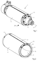
Fig. 1 zeigt einen Heißfolienprägezylinder 1, welcher mit einem gegenüber einer nicht dargestellten Bedruckstoffbahn angeordneten Gegenzylinder 20 ein Prägesystem bildet. Die Bedruckstoffbahn wird zwischen den beiden Zylindern 1, 20 hindurch bewegt und erfährt dabei eine Prägung durch die Prägeform 6. Der Heißfolienprägezylinder 1 besitzt einen Prägezylinder 5, welcher die Prägeform 6 trägt und auf eine Spannachse 2 mit einer Rotationsachse 4 aufgespannt ist. Zum Aufspannen der Prägeform 6 auf den Prägezylinder 5 ist dabei ein Spannsystem 10 vorgesehen, welches anhand der nachfolgenden Figuren näher beschrieben wird. - Wie sich aus
Fig. 2 ergibt, wird die Prägeform 6 auf einen Hohlzylinder 7 mittels des Spannsystems 10 aufgespannt. Dazu besitzt der Hohlzylinder 7 an seinen beiden Enden jeweils einen Absatz 8, auf welchen ein Lagerring 11 aufliegt. Die beiden Lagerringe 11 werden durch einen hier nicht sichtbaren Träger 12 miteinander verbunden. An den beiden Enden der Prägeform 6, d.h. an der Stoßstelle der beiden Enden, wird ein Spalt 3 ausgebildet, welcher wie erkennbar sehr dünn ausgeführt ist. Infolgedessen kommt es beim Prägen zu keinerlei Beeinträchtigungen des Prägebildes. Um die Spannungen der Prägeform 6 auf den Hohlzylinder 7 justieren zu können, ist eine Einstellvorrichtung 15 vorgesehen. -
Fig. 3 zeigt das Spannsystem 10 des Heißfolienprägezylinders 1 im Detail und vor der Montage einer Prägeform 6. Der Hohlzylinder 7 besitzt an seinen beiden stirnseitigen Enden jeweils einen Absatz 8, wobei auf jedem Absatz 8 ein Lagerring 11 gelagert wird. Auch besitzt der Hohlzylinder 7 in seiner Umfangsfläche einen Spalt 3, welcher von einem Träger 12 gefüllt wird. Dieser Träger 12 verbindet die beiden Lagerringe 11 miteinander. Die erste Trennkante 3.1 des Hohlzylinders 7 hat eine kammartige Ausführung. Der Träger 12 hat an seiner angrenzenden Kante eine komplementär dazu ausgeführte, ebenfalls kammartige Ausführung. Damit können der Hohlzylinder 7 und der Träger 12 ineinander eingreifen im Sinne einer Verzahnung. Zwischen der ersten Trennkante 3.1 des Hohlzylinders 7 und der angrenzenden Kante des Trägers 12 sind Federelemente 13 angeordnet, welche hierbei ein Verspannen des Hohlzylinders 7 gegen den Träger 12 bewirken. Zwischen der zweiten Trennkante 3.2 des hohlzylinderförmigen Körpers 7 und dem Träger 12 verbleibt ein Spalt, in welchem sich an einer Prägeform 6 befindliche Laschen, z.B. ausgeführt als Biegekanten, eingeführt werden können, so dass eine hülsenförmige Prägeform 6 flächig auf der Mantelfläche des Hohlzylinders 7 bzw. dem Träger 12 aufliegen kann. Sobald eine jeweilige Prägeform 6 auf den Hohlzylinder 7 aufgesetzt ist, soll diese verspannt werden. Dazu wird das Stellelement 16 der Einstellvorrichtung 15 betätigt, und die Arretierung des hohlzylinderförmigen Körpers 7 relativ zu den Lagerringen 11 gelöst. Dadurch wird die Federkraft der Federn 13 voll wirksam und der hohlzylinderförmige Körper 7 wird relativ zu den Lagerringen 11 durch eine Verstellbewegung V verschoben und damit der Spalt zwischen der zweiten Trennkante 3.2 des Hohlzylinders 7 und der Kante des Trägers 12 weiter verringert und die Spannung auf die Prägeform 6 vergrößert. Auch bei bereits montierter Prägeform 6, wie beispielsweise inFig. 2 dargestellt, kann durch das Stellelement 16 der Einstellvorrichtung 15 eine Feinjustierung der Spannungen vorgenommen werden. Um die Prägeform 6 wieder demontieren zu können, muss das Stellelement 16 der Einstellvorrichtung 15 erneut betätigt werden, um die Verspannung der Prägeform 6 zu reduzieren und gleichzeitig den Spalt zwischen zweiter Trennkante 3.2 des Hohlzylinders 7 und der Kante des Trägers 12 zu vergrößern, so dass die Prägeform 6 von dem Hohlzylinder 7 abgenommen werden kann. - Die Prägeform 6 kann an ihren beiden laschenförmigen Enden Biegekanten mit einem Winkel von in etwa 75 ° an ihrem einen Ende und von ebenfalls in etwa 75 ° an ihrem anderen Ende aufweisen. Um die Prägeform 6 gut aufnehmen zu können, weist der Hohlzylinder 7 an seiner zweiten Trennkante 3.2 und die entsprechende Kante des Trägers 12 unter den gleichen Winkeln geschrägte Kanten auf, so dass eine sichere Anlage der Laschen der Prägeform 6 gewährleistet ist. Die Positionierung der Prägeform 6 relativ zum Hohlzylinder 7 kann zusätzlich noch unterstützt werden durch das Vorsehen von Löchern in den Laschen der Prägeform 6 und komplementär dazu angeordneten Stiften im Bereich des Spalts zwischen zweiter Trennkante 3.2 des Hohlzylinders 7 und dem Träger 12, wobei die Stifte entweder im Träger 12 oder im Hohlzylinder 7 eingelassen sein können.
-
- 1
- Heißfolienprägezylinder
- 2
- Spannachse
- 3
- Spalt
- 3.1
- erste Trennkante
- 3.2
- zweite Trennkante
- 4
- Rotationsachse
- 5
- Prägezylinderkern
- 6
- Prägeform
- 7
- Hohlzylinder
- 8
- Absatz
- 10
- Spannsystem
- 11
- Lagerring
- 12
- Träger
- 13
- Feder
- 14
- kammartige Kontur
- 15
- Einstellvorrichtung
- 16
- Stellelement
- 20
- Position Gegenzylinder
- V
- Verstellbewegung
Claims (9)
- Prägezylinder (1) zum Aufnehmen einer hülsenförmigen Prägeform (6) wobei der Prägezylinder (1) einen hohlzylinderförmigen Körper (7) besitzt aufweisend eine erste und eine zweite in Längsrichtung des Körpers orientierte Trennkante (3.1, 3.2), derart, dass eine durch einen Spalt (3) unterbrochene Mantelfläche gebildet wird,
wobei der Prägezylinder (1) ein Spannsystem (10) zum Aufdehnen des hohlzylinderförmigen Körpers (7) besitzt mit zwei drehbaren, jeweils axial endseitig auf dem hohlzylinderförmigen Körper (7) gelagerten Ringen (11), wobei die Ringe (11) mittels einem sich in dem Spalt (3) befindlichen Träger (12) verbunden sind, und wobei an den Träger (12) und an die erste Trennkante (3.1) Federelemente (13) angestellt sind, deren Federkraft im Wesentlichen in Umfangsrichtung des hohlzylinderförmigen Körpers (7) wirkt. - Prägezylinder nach Anspruch 1,
dadurch gekennzeichnet,
dass der hohlzylinderförmige Körper (7) im Bereich seiner Stirnseiten jeweils einen umlaufenden Absatz (8) aufweist zur Aufnahme jeweils eines Ringes (11) des Spannsystems (10). - Prägezylinder nach einem der vorangehenden Ansprüche,
dadurch gekennzeichnet,
dass die erste Trennkante (3.1) des hohlzylinderförmigen Körpers (7) und eine Seite des Trägers (12) des Spannsystems (12) zueinander komplementäre, kammartige Außenkonturen (14) aufweisen, derart, dass der hohlzylinderförmige Körper (7) und der Träger (12) ineinander greifen. - Prägezylinder nach einem der vorangehenden Ansprüche,
dadurch gekennzeichnet,
dass an dem Spannsystem (10) eine Einstellvorrichtung (14) zum Vergrößern des Abstandes zwischen der zweiten Trennkante (3.2) des hohlzylinderförmigen Körpers (7) und dem Träger (12) des Spannsystems (10) angebracht ist, wobei die Einstellvorrichtung (15) ein Stellelement (16) aufweist, das auf den hohlzylinderförmigen Körper (7) wirkt, um diesen gegen die Federkraft der Federelemente (13) des Spannsystems (10) zu verschieben. - Prägesystem zur Bearbeitung von bahnförmigen oder bogenförmigen Elementen, umfassend einen Prägezylinder (1) mit einem hohlzylinderförmige Körper (7) nach einem der vorangehenden Ansprüche, eine Spannachse (2), eine hülsenförmige Prägeform (6) und einen Gegenzylinder (20),
wobei der Prägezylinder (1) auf der Spannachse (2) gelagert ist, und wobei die Prägeform (6) auf den hohlzylinderförmige Körper (7) aufspannbar ist und mit dem Gegenzylinder (20) zusammenwirkt. - Prägesystem nach Anspruch 5,
dadurch gekennzeichnet,
dass der Prägezylinder einen Kern (5) aus Messing besitzt und/oder die Prägeform (6) aus Magnesium und/oder die Spannachse (2) aus Aluminium gefertigt ist. - Prägesystem nach Anspruch 5 oder 6,
dadurch gekennzeichnet,
dass die Prägeform (6) an ihrem einen Ende eine Biegekante in einem Winkel von etwa 75° und an ihrem anderen Ende eine Biegekante von etwa 75 ° aufweist. - Prägesystem nach einem der Ansprüche 5 bis 7,
dadurch gekennzeichnet,
dass die Prägeform (6) im Randbereich eine reduzierte Dicke aufweist. - Prägesystem nach einem der Ansprüche 5 bis 8,
dadurch gekennzeichnet,
dass der hohlzylinderförmige Körper (7) im Bereich einer Trennkante Stifte und die Prägeform (6) in zumindest einem Randbereich Löcher aufweist, welche ineinander greifen.
Applications Claiming Priority (1)
| Application Number | Priority Date | Filing Date | Title |
|---|---|---|---|
| DE102012020190.7A DE102012020190A1 (de) | 2012-10-15 | 2012-10-15 | Prägezylinder und Prägesystem mit solchem Prägezylinder |
Publications (3)
| Publication Number | Publication Date |
|---|---|
| EP2719547A2 true EP2719547A2 (de) | 2014-04-16 |
| EP2719547A3 EP2719547A3 (de) | 2017-09-27 |
| EP2719547B1 EP2719547B1 (de) | 2020-04-08 |
Family
ID=49223655
Family Applications (1)
| Application Number | Title | Priority Date | Filing Date |
|---|---|---|---|
| EP13185476.2A Active EP2719547B1 (de) | 2012-10-15 | 2013-09-23 | Prägezylinder und Prägesystem mit solchem Prägezylinder |
Country Status (3)
| Country | Link |
|---|---|
| EP (1) | EP2719547B1 (de) |
| CN (1) | CN103722867B (de) |
| DE (1) | DE102012020190A1 (de) |
Cited By (2)
| Publication number | Priority date | Publication date | Assignee | Title |
|---|---|---|---|---|
| EP3560727A1 (de) * | 2013-01-22 | 2019-10-30 | Unilin, BVBA | Verfahren und vorrichtung zur herstellung von produkten mit geprägter oberfläche, und dadurch erhaltene produkte |
| US12617195B2 (en) | 2014-07-31 | 2026-05-05 | Unilin, Bv | Method and installation for manufacturing a floor covering product and floor covering product obtained hereby |
Families Citing this family (1)
| Publication number | Priority date | Publication date | Assignee | Title |
|---|---|---|---|---|
| DE102019216458A1 (de) * | 2019-10-25 | 2021-04-29 | Gallus Ferd. Rüesch AG | Drucksystem für den Rotationssiebdruck, umfassend einen Siebdruckzylinder mit nachgiebigen Oberflächenelementen |
Citations (3)
| Publication number | Priority date | Publication date | Assignee | Title |
|---|---|---|---|---|
| EP0982127A1 (de) | 1998-08-21 | 2000-03-01 | Armin Steuer | Heissprägeverfahren und Heissprägevorrichtung |
| EP1369262A2 (de) | 2002-06-07 | 2003-12-10 | Giesecke & Devrient GmbH | Prägezylinder für die Herstellung von Prägefolien |
| DE19780654B4 (de) | 1996-07-09 | 2004-08-26 | Giesecke & Devrient Gmbh | Prägezylinder für die Herstellung von Prägefolien |
Family Cites Families (9)
| Publication number | Priority date | Publication date | Assignee | Title |
|---|---|---|---|---|
| US1967266A (en) * | 1932-03-12 | 1934-07-24 | Multigraph Co | Blanket-attaching device for rotary printing machines |
| US3156184A (en) * | 1962-02-20 | 1964-11-10 | Harris Intertype Corp | Plate clamp |
| DE8625120U1 (de) * | 1986-09-17 | 1987-09-10 | Siemens AG, 1000 Berlin und 8000 München | Prägerad zum Einprägen von Schriftzeichen und/oder Ziffern |
| ES2099078T3 (es) * | 1989-09-29 | 1997-05-16 | Landis & Gyr Tech Innovat | Dispositivo y procedimiento para estampar texturas delicadas. |
| US20010000859A1 (en) * | 1999-09-14 | 2001-05-10 | Lomax Raymond T. | Web rotary hot stamping soft-die plate system |
| JP5230932B2 (ja) * | 2006-12-27 | 2013-07-10 | 三菱重工印刷紙工機械株式会社 | 印刷胴用スリーブ、印刷機及び印刷胴用スリーブの内周層着脱方法 |
| CN201217295Y (zh) * | 2008-05-30 | 2009-04-08 | 宁波欣达印刷机器有限公司 | 印刷机的调版装置 |
| EP2275259A1 (de) * | 2009-07-14 | 2011-01-19 | Pantec GS Systems AG | Druck- oder Prägewerk und Arbeitszylinder hierfür |
| CN201941254U (zh) * | 2011-03-02 | 2011-08-24 | 新乡市新机创新机械有限公司 | 一种消除虚影的靠板墨辊 |
-
2012
- 2012-10-15 DE DE102012020190.7A patent/DE102012020190A1/de not_active Withdrawn
-
2013
- 2013-09-04 CN CN201310397648.2A patent/CN103722867B/zh active Active
- 2013-09-23 EP EP13185476.2A patent/EP2719547B1/de active Active
Patent Citations (3)
| Publication number | Priority date | Publication date | Assignee | Title |
|---|---|---|---|---|
| DE19780654B4 (de) | 1996-07-09 | 2004-08-26 | Giesecke & Devrient Gmbh | Prägezylinder für die Herstellung von Prägefolien |
| EP0982127A1 (de) | 1998-08-21 | 2000-03-01 | Armin Steuer | Heissprägeverfahren und Heissprägevorrichtung |
| EP1369262A2 (de) | 2002-06-07 | 2003-12-10 | Giesecke & Devrient GmbH | Prägezylinder für die Herstellung von Prägefolien |
Cited By (2)
| Publication number | Priority date | Publication date | Assignee | Title |
|---|---|---|---|---|
| EP3560727A1 (de) * | 2013-01-22 | 2019-10-30 | Unilin, BVBA | Verfahren und vorrichtung zur herstellung von produkten mit geprägter oberfläche, und dadurch erhaltene produkte |
| US12617195B2 (en) | 2014-07-31 | 2026-05-05 | Unilin, Bv | Method and installation for manufacturing a floor covering product and floor covering product obtained hereby |
Also Published As
| Publication number | Publication date |
|---|---|
| EP2719547A3 (de) | 2017-09-27 |
| CN103722867B (zh) | 2017-03-22 |
| EP2719547B1 (de) | 2020-04-08 |
| DE102012020190A1 (de) | 2014-04-17 |
| CN103722867A (zh) | 2014-04-16 |
Similar Documents
| Publication | Publication Date | Title |
|---|---|---|
| EP3131794B1 (de) | Wischeranlage | |
| WO2018036956A1 (de) | Gebaute rotorwelle asymmetrischer bauweise sowie rotor und verfahren zur herstellung der gebauten rotorwelle und des rotors | |
| EP2719547B1 (de) | Prägezylinder und Prägesystem mit solchem Prägezylinder | |
| DE102015014368A1 (de) | Klappflügel für einen Flugkörper sowie einen Flugkörper mit mindestens einem daran angeordneten Klappflügel | |
| DE102010005602A1 (de) | Nockenwellenversteller | |
| EP1104347A1 (de) | Haltevorrichtung für flexodruck-druckhülsen | |
| EP3027926B2 (de) | Scheibenbremse, insbesondere für nutzfahrzeuge, sowie bremsbelag einer solchen scheibenbremse | |
| EP2746176B1 (de) | Auflageteller mit Druckelementen | |
| WO2003031305A1 (de) | Wickelhülse | |
| EP1827831B1 (de) | Druckplattenzylinder mit austauschbarer hülse | |
| DE102013006698A1 (de) | Rotationssiebdrucksieb, Montagevorrichtung, Belichtungsvorrichtung und Waschvorrichtung mit Schnellverschluss | |
| EP3208088A2 (de) | Vorrichtung zum heissfolienprägen | |
| EP1572461B1 (de) | Drucktucheinheit für einen drucktuchzylinder sowie verfahren zur herstellung einer drucktucheinheit | |
| DE102010019726A1 (de) | Vorrichtung zum Einführen von Blättern in eine mit einem Blatteinzug versehene Druckpresse | |
| DE102014006089A1 (de) | Falzvorrichtung zum Falzen eines Blechbauteils | |
| DE102015010314B4 (de) | Arretierungsanordnung | |
| DE10318751A1 (de) | Wellen-Naben-Verbindung zum Sichern von Lagern, Verfahren und Vorrichtung zur Herstellung von Wellen-Naben-Verbindungen | |
| DE102011122146B4 (de) | Verfahren zur Aufbereitung eines Magnet- oder Druckzylinders einer Stanz- oder Druckmaschine und durch das Verfahren aufbereiteter Magnet- oder Druckzylinder | |
| EP2377686B1 (de) | Hülse zur Montage auf einen Druckmaschinenzylinder | |
| EP2057017A2 (de) | Druckwerk einer tiefdruckmaschine | |
| EP3895896B1 (de) | Trommel für eine druckvorrichtung, druckvorrichtung und verfahren zum zeitweisen fixieren eines bogenförmigen substrats an einer trommel | |
| EP3403844A1 (de) | Verfahren zum herstellen eines sicherheitselements mit einem metallisierten reliefbereich und zugehöriges sicherheitselement | |
| CH695152A5 (de) | Falzzylinder mit mindestens einem Expansions-Segment. | |
| DE102018129107A1 (de) | Verfahren zum additiven Herstellen einer Baugruppe sowie Baugruppe | |
| EP1284859B1 (de) | Magnetischer aufzug eines formzylinders einer rotationsdruckmaschine |
Legal Events
| Date | Code | Title | Description |
|---|---|---|---|
| PUAI | Public reference made under article 153(3) epc to a published international application that has entered the european phase |
Free format text: ORIGINAL CODE: 0009012 |
|
| AK | Designated contracting states |
Kind code of ref document: A2 Designated state(s): AL AT BE BG CH CY CZ DE DK EE ES FI FR GB GR HR HU IE IS IT LI LT LU LV MC MK MT NL NO PL PT RO RS SE SI SK SM TR |
|
| AX | Request for extension of the european patent |
Extension state: BA ME |
|
| PUAL | Search report despatched |
Free format text: ORIGINAL CODE: 0009013 |
|
| AK | Designated contracting states |
Kind code of ref document: A3 Designated state(s): AL AT BE BG CH CY CZ DE DK EE ES FI FR GB GR HR HU IE IS IT LI LT LU LV MC MK MT NL NO PL PT RO RS SE SI SK SM TR |
|
| AX | Request for extension of the european patent |
Extension state: BA ME |
|
| RIC1 | Information provided on ipc code assigned before grant |
Ipc: B44B 5/02 20060101ALI20170822BHEP Ipc: B41F 19/06 20060101ALI20170822BHEP Ipc: B44B 5/00 20060101AFI20170822BHEP |
|
| STAA | Information on the status of an ep patent application or granted ep patent |
Free format text: STATUS: REQUEST FOR EXAMINATION WAS MADE |
|
| 17P | Request for examination filed |
Effective date: 20180327 |
|
| RBV | Designated contracting states (corrected) |
Designated state(s): AL AT BE BG CH CY CZ DE DK EE ES FI FR GB GR HR HU IE IS IT LI LT LU LV MC MK MT NL NO PL PT RO RS SE SI SK SM TR |
|
| STAA | Information on the status of an ep patent application or granted ep patent |
Free format text: STATUS: EXAMINATION IS IN PROGRESS |
|
| 17Q | First examination report despatched |
Effective date: 20180807 |
|
| GRAP | Despatch of communication of intention to grant a patent |
Free format text: ORIGINAL CODE: EPIDOSNIGR1 |
|
| STAA | Information on the status of an ep patent application or granted ep patent |
Free format text: STATUS: GRANT OF PATENT IS INTENDED |
|
| INTG | Intention to grant announced |
Effective date: 20200102 |
|
| GRAS | Grant fee paid |
Free format text: ORIGINAL CODE: EPIDOSNIGR3 |
|
| GRAA | (expected) grant |
Free format text: ORIGINAL CODE: 0009210 |
|
| STAA | Information on the status of an ep patent application or granted ep patent |
Free format text: STATUS: THE PATENT HAS BEEN GRANTED |
|
| AK | Designated contracting states |
Kind code of ref document: B1 Designated state(s): AL AT BE BG CH CY CZ DE DK EE ES FI FR GB GR HR HU IE IS IT LI LT LU LV MC MK MT NL NO PL PT RO RS SE SI SK SM TR |
|
| REG | Reference to a national code |
Ref country code: CH Ref legal event code: EP Ref country code: AT Ref legal event code: REF Ref document number: 1253867 Country of ref document: AT Kind code of ref document: T Effective date: 20200415 |
|
| REG | Reference to a national code |
Ref country code: IE Ref legal event code: FG4D Free format text: LANGUAGE OF EP DOCUMENT: GERMAN |
|
| REG | Reference to a national code |
Ref country code: DE Ref legal event code: R096 Ref document number: 502013014552 Country of ref document: DE |
|
| REG | Reference to a national code |
Ref country code: NL Ref legal event code: MP Effective date: 20200408 |
|
| REG | Reference to a national code |
Ref country code: LT Ref legal event code: MG4D |
|
| PG25 | Lapsed in a contracting state [announced via postgrant information from national office to epo] |
Ref country code: NO Free format text: LAPSE BECAUSE OF FAILURE TO SUBMIT A TRANSLATION OF THE DESCRIPTION OR TO PAY THE FEE WITHIN THE PRESCRIBED TIME-LIMIT Effective date: 20200708 Ref country code: PT Free format text: LAPSE BECAUSE OF FAILURE TO SUBMIT A TRANSLATION OF THE DESCRIPTION OR TO PAY THE FEE WITHIN THE PRESCRIBED TIME-LIMIT Effective date: 20200817 Ref country code: GR Free format text: LAPSE BECAUSE OF FAILURE TO SUBMIT A TRANSLATION OF THE DESCRIPTION OR TO PAY THE FEE WITHIN THE PRESCRIBED TIME-LIMIT Effective date: 20200709 Ref country code: SE Free format text: LAPSE BECAUSE OF FAILURE TO SUBMIT A TRANSLATION OF THE DESCRIPTION OR TO PAY THE FEE WITHIN THE PRESCRIBED TIME-LIMIT Effective date: 20200408 Ref country code: IS Free format text: LAPSE BECAUSE OF FAILURE TO SUBMIT A TRANSLATION OF THE DESCRIPTION OR TO PAY THE FEE WITHIN THE PRESCRIBED TIME-LIMIT Effective date: 20200808 Ref country code: FI Free format text: LAPSE BECAUSE OF FAILURE TO SUBMIT A TRANSLATION OF THE DESCRIPTION OR TO PAY THE FEE WITHIN THE PRESCRIBED TIME-LIMIT Effective date: 20200408 Ref country code: LT Free format text: LAPSE BECAUSE OF FAILURE TO SUBMIT A TRANSLATION OF THE DESCRIPTION OR TO PAY THE FEE WITHIN THE PRESCRIBED TIME-LIMIT Effective date: 20200408 Ref country code: NL Free format text: LAPSE BECAUSE OF FAILURE TO SUBMIT A TRANSLATION OF THE DESCRIPTION OR TO PAY THE FEE WITHIN THE PRESCRIBED TIME-LIMIT Effective date: 20200408 |
|
| PG25 | Lapsed in a contracting state [announced via postgrant information from national office to epo] |
Ref country code: RS Free format text: LAPSE BECAUSE OF FAILURE TO SUBMIT A TRANSLATION OF THE DESCRIPTION OR TO PAY THE FEE WITHIN THE PRESCRIBED TIME-LIMIT Effective date: 20200408 Ref country code: HR Free format text: LAPSE BECAUSE OF FAILURE TO SUBMIT A TRANSLATION OF THE DESCRIPTION OR TO PAY THE FEE WITHIN THE PRESCRIBED TIME-LIMIT Effective date: 20200408 Ref country code: LV Free format text: LAPSE BECAUSE OF FAILURE TO SUBMIT A TRANSLATION OF THE DESCRIPTION OR TO PAY THE FEE WITHIN THE PRESCRIBED TIME-LIMIT Effective date: 20200408 Ref country code: BG Free format text: LAPSE BECAUSE OF FAILURE TO SUBMIT A TRANSLATION OF THE DESCRIPTION OR TO PAY THE FEE WITHIN THE PRESCRIBED TIME-LIMIT Effective date: 20200708 |
|
| PG25 | Lapsed in a contracting state [announced via postgrant information from national office to epo] |
Ref country code: AL Free format text: LAPSE BECAUSE OF FAILURE TO SUBMIT A TRANSLATION OF THE DESCRIPTION OR TO PAY THE FEE WITHIN THE PRESCRIBED TIME-LIMIT Effective date: 20200408 |
|
| REG | Reference to a national code |
Ref country code: DE Ref legal event code: R097 Ref document number: 502013014552 Country of ref document: DE |
|
| PG25 | Lapsed in a contracting state [announced via postgrant information from national office to epo] |
Ref country code: DK Free format text: LAPSE BECAUSE OF FAILURE TO SUBMIT A TRANSLATION OF THE DESCRIPTION OR TO PAY THE FEE WITHIN THE PRESCRIBED TIME-LIMIT Effective date: 20200408 Ref country code: IT Free format text: LAPSE BECAUSE OF FAILURE TO SUBMIT A TRANSLATION OF THE DESCRIPTION OR TO PAY THE FEE WITHIN THE PRESCRIBED TIME-LIMIT Effective date: 20200408 Ref country code: SM Free format text: LAPSE BECAUSE OF FAILURE TO SUBMIT A TRANSLATION OF THE DESCRIPTION OR TO PAY THE FEE WITHIN THE PRESCRIBED TIME-LIMIT Effective date: 20200408 Ref country code: EE Free format text: LAPSE BECAUSE OF FAILURE TO SUBMIT A TRANSLATION OF THE DESCRIPTION OR TO PAY THE FEE WITHIN THE PRESCRIBED TIME-LIMIT Effective date: 20200408 Ref country code: CZ Free format text: LAPSE BECAUSE OF FAILURE TO SUBMIT A TRANSLATION OF THE DESCRIPTION OR TO PAY THE FEE WITHIN THE PRESCRIBED TIME-LIMIT Effective date: 20200408 Ref country code: RO Free format text: LAPSE BECAUSE OF FAILURE TO SUBMIT A TRANSLATION OF THE DESCRIPTION OR TO PAY THE FEE WITHIN THE PRESCRIBED TIME-LIMIT Effective date: 20200408 Ref country code: ES Free format text: LAPSE BECAUSE OF FAILURE TO SUBMIT A TRANSLATION OF THE DESCRIPTION OR TO PAY THE FEE WITHIN THE PRESCRIBED TIME-LIMIT Effective date: 20200408 |
|
| PLBE | No opposition filed within time limit |
Free format text: ORIGINAL CODE: 0009261 |
|
| STAA | Information on the status of an ep patent application or granted ep patent |
Free format text: STATUS: NO OPPOSITION FILED WITHIN TIME LIMIT |
|
| PG25 | Lapsed in a contracting state [announced via postgrant information from national office to epo] |
Ref country code: SK Free format text: LAPSE BECAUSE OF FAILURE TO SUBMIT A TRANSLATION OF THE DESCRIPTION OR TO PAY THE FEE WITHIN THE PRESCRIBED TIME-LIMIT Effective date: 20200408 Ref country code: PL Free format text: LAPSE BECAUSE OF FAILURE TO SUBMIT A TRANSLATION OF THE DESCRIPTION OR TO PAY THE FEE WITHIN THE PRESCRIBED TIME-LIMIT Effective date: 20200408 |
|
| 26N | No opposition filed |
Effective date: 20210112 |
|
| PG25 | Lapsed in a contracting state [announced via postgrant information from national office to epo] |
Ref country code: MC Free format text: LAPSE BECAUSE OF FAILURE TO SUBMIT A TRANSLATION OF THE DESCRIPTION OR TO PAY THE FEE WITHIN THE PRESCRIBED TIME-LIMIT Effective date: 20200408 |
|
| GBPC | Gb: european patent ceased through non-payment of renewal fee |
Effective date: 20200923 |
|
| PG25 | Lapsed in a contracting state [announced via postgrant information from national office to epo] |
Ref country code: SI Free format text: LAPSE BECAUSE OF FAILURE TO SUBMIT A TRANSLATION OF THE DESCRIPTION OR TO PAY THE FEE WITHIN THE PRESCRIBED TIME-LIMIT Effective date: 20200408 |
|
| REG | Reference to a national code |
Ref country code: BE Ref legal event code: MM Effective date: 20200930 |
|
| PG25 | Lapsed in a contracting state [announced via postgrant information from national office to epo] |
Ref country code: LU Free format text: LAPSE BECAUSE OF NON-PAYMENT OF DUE FEES Effective date: 20200923 |
|
| PG25 | Lapsed in a contracting state [announced via postgrant information from national office to epo] |
Ref country code: FR Free format text: LAPSE BECAUSE OF NON-PAYMENT OF DUE FEES Effective date: 20200930 |
|
| PG25 | Lapsed in a contracting state [announced via postgrant information from national office to epo] |
Ref country code: BE Free format text: LAPSE BECAUSE OF NON-PAYMENT OF DUE FEES Effective date: 20200930 Ref country code: GB Free format text: LAPSE BECAUSE OF NON-PAYMENT OF DUE FEES Effective date: 20200923 Ref country code: IE Free format text: LAPSE BECAUSE OF NON-PAYMENT OF DUE FEES Effective date: 20200923 |
|
| REG | Reference to a national code |
Ref country code: AT Ref legal event code: MM01 Ref document number: 1253867 Country of ref document: AT Kind code of ref document: T Effective date: 20200923 |
|
| PG25 | Lapsed in a contracting state [announced via postgrant information from national office to epo] |
Ref country code: AT Free format text: LAPSE BECAUSE OF NON-PAYMENT OF DUE FEES Effective date: 20200923 |
|
| PG25 | Lapsed in a contracting state [announced via postgrant information from national office to epo] |
Ref country code: TR Free format text: LAPSE BECAUSE OF FAILURE TO SUBMIT A TRANSLATION OF THE DESCRIPTION OR TO PAY THE FEE WITHIN THE PRESCRIBED TIME-LIMIT Effective date: 20200408 Ref country code: MT Free format text: LAPSE BECAUSE OF FAILURE TO SUBMIT A TRANSLATION OF THE DESCRIPTION OR TO PAY THE FEE WITHIN THE PRESCRIBED TIME-LIMIT Effective date: 20200408 Ref country code: CY Free format text: LAPSE BECAUSE OF FAILURE TO SUBMIT A TRANSLATION OF THE DESCRIPTION OR TO PAY THE FEE WITHIN THE PRESCRIBED TIME-LIMIT Effective date: 20200408 |
|
| PG25 | Lapsed in a contracting state [announced via postgrant information from national office to epo] |
Ref country code: MK Free format text: LAPSE BECAUSE OF FAILURE TO SUBMIT A TRANSLATION OF THE DESCRIPTION OR TO PAY THE FEE WITHIN THE PRESCRIBED TIME-LIMIT Effective date: 20200408 |
|
| P01 | Opt-out of the competence of the unified patent court (upc) registered |
Effective date: 20230511 |
|
| REG | Reference to a national code |
Ref country code: CH Ref legal event code: U11 Free format text: ST27 STATUS EVENT CODE: U-0-0-U10-U11 (AS PROVIDED BY THE NATIONAL OFFICE) Effective date: 20251001 |
|
| PGFP | Annual fee paid to national office [announced via postgrant information from national office to epo] |
Ref country code: DE Payment date: 20250930 Year of fee payment: 13 |
|
| PGFP | Annual fee paid to national office [announced via postgrant information from national office to epo] |
Ref country code: CH Payment date: 20251001 Year of fee payment: 13 |