EP2719422A1 - Implantierbare multipolare Mikrosonde zur Erfassung/Stimulation - Google Patents
Implantierbare multipolare Mikrosonde zur Erfassung/Stimulation Download PDFInfo
- Publication number
- EP2719422A1 EP2719422A1 EP13169168.5A EP13169168A EP2719422A1 EP 2719422 A1 EP2719422 A1 EP 2719422A1 EP 13169168 A EP13169168 A EP 13169168A EP 2719422 A1 EP2719422 A1 EP 2719422A1
- Authority
- EP
- European Patent Office
- Prior art keywords
- probe
- microcables
- microprobe
- stimulation
- strand
- Prior art date
- Legal status (The legal status is an assumption and is not a legal conclusion. Google has not performed a legal analysis and makes no representation as to the accuracy of the status listed.)
- Granted
Links
- 230000000638 stimulation Effects 0.000 title claims abstract description 35
- 238000001514 detection method Methods 0.000 title claims abstract description 15
- 238000009413 insulation Methods 0.000 claims abstract description 15
- 229920000642 polymer Polymers 0.000 claims abstract description 10
- 239000000523 sample Substances 0.000 claims description 49
- 239000000463 material Substances 0.000 claims description 25
- BASFCYQUMIYNBI-UHFFFAOYSA-N platinum Chemical compound [Pt] BASFCYQUMIYNBI-UHFFFAOYSA-N 0.000 claims description 15
- 239000010931 gold Substances 0.000 claims description 12
- KDLHZDBZIXYQEI-UHFFFAOYSA-N Palladium Chemical compound [Pd] KDLHZDBZIXYQEI-UHFFFAOYSA-N 0.000 claims description 9
- 239000010936 titanium Substances 0.000 claims description 9
- 239000003292 glue Substances 0.000 claims description 8
- 238000002955 isolation Methods 0.000 claims description 8
- RTAQQCXQSZGOHL-UHFFFAOYSA-N Titanium Chemical compound [Ti] RTAQQCXQSZGOHL-UHFFFAOYSA-N 0.000 claims description 6
- PCHJSUWPFVWCPO-UHFFFAOYSA-N gold Chemical compound [Au] PCHJSUWPFVWCPO-UHFFFAOYSA-N 0.000 claims description 6
- 229910052737 gold Inorganic materials 0.000 claims description 6
- 230000001926 lymphatic effect Effects 0.000 claims description 6
- 229910052697 platinum Inorganic materials 0.000 claims description 6
- 230000009467 reduction Effects 0.000 claims description 6
- 239000010948 rhodium Substances 0.000 claims description 6
- 229910052715 tantalum Inorganic materials 0.000 claims description 6
- GUVRBAGPIYLISA-UHFFFAOYSA-N tantalum atom Chemical compound [Ta] GUVRBAGPIYLISA-UHFFFAOYSA-N 0.000 claims description 6
- 229910052719 titanium Inorganic materials 0.000 claims description 6
- WFKWXMTUELFFGS-UHFFFAOYSA-N tungsten Chemical compound [W] WFKWXMTUELFFGS-UHFFFAOYSA-N 0.000 claims description 6
- 229910052721 tungsten Inorganic materials 0.000 claims description 6
- 239000010937 tungsten Substances 0.000 claims description 6
- 238000004026 adhesive bonding Methods 0.000 claims description 5
- 230000004936 stimulating effect Effects 0.000 claims description 5
- 229910052741 iridium Inorganic materials 0.000 claims description 4
- GKOZUEZYRPOHIO-UHFFFAOYSA-N iridium atom Chemical compound [Ir] GKOZUEZYRPOHIO-UHFFFAOYSA-N 0.000 claims description 4
- 229910001000 nickel titanium Inorganic materials 0.000 claims description 4
- 238000003466 welding Methods 0.000 claims description 4
- 229910000531 Co alloy Inorganic materials 0.000 claims description 3
- ZOKXTWBITQBERF-UHFFFAOYSA-N Molybdenum Chemical compound [Mo] ZOKXTWBITQBERF-UHFFFAOYSA-N 0.000 claims description 3
- 229910045601 alloy Inorganic materials 0.000 claims description 3
- 239000000956 alloy Substances 0.000 claims description 3
- 239000002131 composite material Substances 0.000 claims description 3
- 229920002313 fluoropolymer Polymers 0.000 claims description 3
- 229910052750 molybdenum Inorganic materials 0.000 claims description 3
- 239000011733 molybdenum Substances 0.000 claims description 3
- 229910052763 palladium Inorganic materials 0.000 claims description 3
- 239000010970 precious metal Substances 0.000 claims description 3
- 229910052703 rhodium Inorganic materials 0.000 claims description 3
- MHOVAHRLVXNVSD-UHFFFAOYSA-N rhodium atom Chemical compound [Rh] MHOVAHRLVXNVSD-UHFFFAOYSA-N 0.000 claims description 3
- 239000010935 stainless steel Substances 0.000 claims description 3
- 229910001220 stainless steel Inorganic materials 0.000 claims description 3
- 239000004811 fluoropolymer Substances 0.000 claims description 2
- HWLDNSXPUQTBOD-UHFFFAOYSA-N platinum-iridium alloy Chemical compound [Ir].[Pt] HWLDNSXPUQTBOD-UHFFFAOYSA-N 0.000 claims description 2
- 210000001519 tissue Anatomy 0.000 description 11
- 239000004020 conductor Substances 0.000 description 9
- 210000003462 vein Anatomy 0.000 description 8
- 238000000034 method Methods 0.000 description 7
- 238000002513 implantation Methods 0.000 description 6
- 230000002093 peripheral effect Effects 0.000 description 6
- 230000007774 longterm Effects 0.000 description 5
- 238000011282 treatment Methods 0.000 description 5
- 230000000694 effects Effects 0.000 description 4
- 229920000840 ethylene tetrafluoroethylene copolymer Polymers 0.000 description 4
- 230000002349 favourable effect Effects 0.000 description 4
- 238000010438 heat treatment Methods 0.000 description 4
- 229920000728 polyester Polymers 0.000 description 4
- 238000002788 crimping Methods 0.000 description 3
- 238000005516 engineering process Methods 0.000 description 3
- 210000000056 organ Anatomy 0.000 description 3
- 230000007704 transition Effects 0.000 description 3
- 229920000297 Rayon Polymers 0.000 description 2
- 241000897276 Termes Species 0.000 description 2
- 230000009471 action Effects 0.000 description 2
- 230000003872 anastomosis Effects 0.000 description 2
- 238000005452 bending Methods 0.000 description 2
- 230000008901 benefit Effects 0.000 description 2
- 230000000747 cardiac effect Effects 0.000 description 2
- 230000007797 corrosion Effects 0.000 description 2
- 238000005260 corrosion Methods 0.000 description 2
- 230000002500 effect on skin Effects 0.000 description 2
- 230000005684 electric field Effects 0.000 description 2
- QHSJIZLJUFMIFP-UHFFFAOYSA-N ethene;1,1,2,2-tetrafluoroethene Chemical group C=C.FC(F)=C(F)F QHSJIZLJUFMIFP-UHFFFAOYSA-N 0.000 description 2
- 238000003384 imaging method Methods 0.000 description 2
- 239000007943 implant Substances 0.000 description 2
- 230000006872 improvement Effects 0.000 description 2
- 210000005240 left ventricle Anatomy 0.000 description 2
- 229910052751 metal Inorganic materials 0.000 description 2
- 239000002184 metal Substances 0.000 description 2
- 230000000926 neurological effect Effects 0.000 description 2
- 230000000750 progressive effect Effects 0.000 description 2
- 239000002964 rayon Substances 0.000 description 2
- 239000000126 substance Substances 0.000 description 2
- 230000009466 transformation Effects 0.000 description 2
- 239000004593 Epoxy Substances 0.000 description 1
- 201000008450 Intracranial aneurysm Diseases 0.000 description 1
- 208000012902 Nervous system disease Diseases 0.000 description 1
- 208000025966 Neurological disease Diseases 0.000 description 1
- 208000018737 Parkinson disease Diseases 0.000 description 1
- 241000287107 Passer Species 0.000 description 1
- 239000000853 adhesive Substances 0.000 description 1
- 230000001070 adhesive effect Effects 0.000 description 1
- 238000013459 approach Methods 0.000 description 1
- 230000006793 arrhythmia Effects 0.000 description 1
- 206010003119 arrhythmia Diseases 0.000 description 1
- 230000005540 biological transmission Effects 0.000 description 1
- 210000001124 body fluid Anatomy 0.000 description 1
- 239000010839 body fluid Substances 0.000 description 1
- 210000004556 brain Anatomy 0.000 description 1
- OVXZVDMCQPLHIY-QXGOIDDHSA-L calcium;4-[[(2r)-2,4-dihydroxy-3,3-dimethylbutanoyl]amino]butanoate Chemical compound [Ca+2].OCC(C)(C)[C@@H](O)C(=O)NCCCC([O-])=O.OCC(C)(C)[C@@H](O)C(=O)NCCCC([O-])=O OVXZVDMCQPLHIY-QXGOIDDHSA-L 0.000 description 1
- 230000002490 cerebral effect Effects 0.000 description 1
- 230000008859 change Effects 0.000 description 1
- 150000001875 compounds Chemical class 0.000 description 1
- 210000003748 coronary sinus Anatomy 0.000 description 1
- 230000001419 dependent effect Effects 0.000 description 1
- 238000002059 diagnostic imaging Methods 0.000 description 1
- 238000009792 diffusion process Methods 0.000 description 1
- 238000010292 electrical insulation Methods 0.000 description 1
- 239000003792 electrolyte Substances 0.000 description 1
- 206010015037 epilepsy Diseases 0.000 description 1
- 230000017525 heat dissipation Effects 0.000 description 1
- 208000014674 injury Diseases 0.000 description 1
- 238000003780 insertion Methods 0.000 description 1
- 230000037431 insertion Effects 0.000 description 1
- 239000012212 insulator Substances 0.000 description 1
- 238000000608 laser ablation Methods 0.000 description 1
- 210000004324 lymphatic system Anatomy 0.000 description 1
- 238000004519 manufacturing process Methods 0.000 description 1
- 238000005259 measurement Methods 0.000 description 1
- 238000002844 melting Methods 0.000 description 1
- 230000008018 melting Effects 0.000 description 1
- 150000002739 metals Chemical class 0.000 description 1
- 238000012544 monitoring process Methods 0.000 description 1
- 230000005405 multipole Effects 0.000 description 1
- 210000003205 muscle Anatomy 0.000 description 1
- 210000004165 myocardium Anatomy 0.000 description 1
- 210000005036 nerve Anatomy 0.000 description 1
- 230000004007 neuromodulation Effects 0.000 description 1
- HLXZNVUGXRDIFK-UHFFFAOYSA-N nickel titanium Chemical compound [Ti].[Ti].[Ti].[Ti].[Ti].[Ti].[Ti].[Ti].[Ti].[Ti].[Ti].[Ni].[Ni].[Ni].[Ni].[Ni].[Ni].[Ni].[Ni].[Ni].[Ni].[Ni].[Ni].[Ni].[Ni] HLXZNVUGXRDIFK-UHFFFAOYSA-N 0.000 description 1
- 230000010287 polarization Effects 0.000 description 1
- -1 polyethylene terephthalate Polymers 0.000 description 1
- 229920000139 polyethylene terephthalate Polymers 0.000 description 1
- 239000005020 polyethylene terephthalate Substances 0.000 description 1
- 230000002028 premature Effects 0.000 description 1
- 230000008569 process Effects 0.000 description 1
- 230000008054 signal transmission Effects 0.000 description 1
- 238000002560 therapeutic procedure Methods 0.000 description 1
- 230000008733 trauma Effects 0.000 description 1
- 210000000264 venule Anatomy 0.000 description 1
Images


Classifications
-
- A—HUMAN NECESSITIES
- A61—MEDICAL OR VETERINARY SCIENCE; HYGIENE
- A61N—ELECTROTHERAPY; MAGNETOTHERAPY; RADIATION THERAPY; ULTRASOUND THERAPY
- A61N1/00—Electrotherapy; Circuits therefor
- A61N1/02—Details
- A61N1/04—Electrodes
- A61N1/05—Electrodes for implantation or insertion into the body, e.g. heart electrode
-
- A—HUMAN NECESSITIES
- A61—MEDICAL OR VETERINARY SCIENCE; HYGIENE
- A61B—DIAGNOSIS; SURGERY; IDENTIFICATION
- A61B5/00—Measuring for diagnostic purposes; Identification of persons
- A61B5/24—Detecting, measuring or recording bioelectric or biomagnetic signals of the body or parts thereof
-
- A—HUMAN NECESSITIES
- A61—MEDICAL OR VETERINARY SCIENCE; HYGIENE
- A61N—ELECTROTHERAPY; MAGNETOTHERAPY; RADIATION THERAPY; ULTRASOUND THERAPY
- A61N1/00—Electrotherapy; Circuits therefor
- A61N1/02—Details
- A61N1/04—Electrodes
- A61N1/05—Electrodes for implantation or insertion into the body, e.g. heart electrode
- A61N1/056—Transvascular endocardial electrode systems
-
- A—HUMAN NECESSITIES
- A61—MEDICAL OR VETERINARY SCIENCE; HYGIENE
- A61N—ELECTROTHERAPY; MAGNETOTHERAPY; RADIATION THERAPY; ULTRASOUND THERAPY
- A61N1/00—Electrotherapy; Circuits therefor
- A61N1/18—Applying electric currents by contact electrodes
- A61N1/32—Applying electric currents by contact electrodes alternating or intermittent currents
- A61N1/36—Applying electric currents by contact electrodes alternating or intermittent currents for stimulation
- A61N1/372—Arrangements in connection with the implantation of stimulators
-
- A—HUMAN NECESSITIES
- A61—MEDICAL OR VETERINARY SCIENCE; HYGIENE
- A61N—ELECTROTHERAPY; MAGNETOTHERAPY; RADIATION THERAPY; ULTRASOUND THERAPY
- A61N1/00—Electrotherapy; Circuits therefor
- A61N1/02—Details
- A61N1/04—Electrodes
- A61N1/05—Electrodes for implantation or insertion into the body, e.g. heart electrode
- A61N1/056—Transvascular endocardial electrode systems
- A61N2001/0585—Coronary sinus electrodes
-
- Y—GENERAL TAGGING OF NEW TECHNOLOGICAL DEVELOPMENTS; GENERAL TAGGING OF CROSS-SECTIONAL TECHNOLOGIES SPANNING OVER SEVERAL SECTIONS OF THE IPC; TECHNICAL SUBJECTS COVERED BY FORMER USPC CROSS-REFERENCE ART COLLECTIONS [XRACs] AND DIGESTS
- Y10—TECHNICAL SUBJECTS COVERED BY FORMER USPC
- Y10T—TECHNICAL SUBJECTS COVERED BY FORMER US CLASSIFICATION
- Y10T29/00—Metal working
- Y10T29/49—Method of mechanical manufacture
- Y10T29/49002—Electrical device making
- Y10T29/49117—Conductor or circuit manufacturing
- Y10T29/49204—Contact or terminal manufacturing
- Y10T29/49224—Contact or terminal manufacturing with coating
Definitions
- the invention relates generally to "active implantable medical devices" as defined by Council Directive 90/385 / EEC of 20 June 1990.
- This definition includes in particular cardiac implants responsible for monitoring cardiac activity and generating pacing, defibrillation and / or resynchronization pulses in case of arrhythmia detected by the apparatus, and / or for detecting electrical activity. . It also includes neurological devices, cochlear implants, diffusion pumps for medical substances, implanted biological sensors, etc.
- These devices comprise a housing generally designated “generator”, electrically and mechanically connected to one or more intracorporeal “probes” provided with (s) electrodes intended to come into contact with the tissues on which it is desired to apply stimulation pulses and / or collect an electrical signal: myocardium, nerve, muscle ...
- the present invention more specifically relates to a microprobe of detection / stimulation intended to be implanted in venous, arterial or lymphatic networks.
- the current architecture of the probes meeting these needs can be summarized as a generally hollow structure to allow the passage of a mandrel or a guide wire, and comprising insulated conductor cable components connected to mechanical electrodes for ensure electrical conductivity, radiopacity, etc.
- any stiffness transition zone is likely to induce risks of fatigue, difficulties to sterilize due to the presence of areas of difficult access, and problems with the holding of connection junctions. conductors at the connection with the electrodes and the connector.
- the current size of the implantable probes is typically in the range of 4 to 6 French (1.33 to 2 mm).
- microsondes With this type of technology to treat new regions difficult to reach today, this by means of small stimulation probes, or "microworlds”, with a great robustness in order to guarantee the long-term biostability. With microsondes of reduced size, it is possible to consider in particular the passage of anastomoses to establish for example a device for stimulating the left ventricle via two distinct areas.
- microwaves across the relevant vessel network to their target location. Their implementation could be carried out, because of their reduced size, by guiding devices used today in interventional neuroradiology for the release of springs ( coils ) during the treatment of intracranial aneurysms. In particular, microworlds of 1.5 French would be compatible with 1.6 French inner diameter catheters.
- multipole probes in applications related to the function of "electronic repositioning", which offers many opportunities for tissue stimulation through the choice and polarization of certain conduction lines among several included in the microprobe. This technique allows to program zones of stimulation according to the therapy, very interesting property in particular in neurology.
- the EP 2 455 131 A1 envisions a probe grouping a plurality of distinct monopolar microprobes.
- the probe body that groups these microwonders is provided along its length with several lateral openings from which successively emerge respective microcables.
- Each of these microcables forms a monopolar line extending into a vessel homologous to the coronary network, which allows to stimulate by means of the same probe several vessels (each by a monopolar microcable) and thus cover a large area of the left ventricle. But if we consider separately each of the microworlds, they have only one electrical conductor and therefore can not be repositioned electronically.
- the object of the present invention is to provide a small microprobe that would be in accordance with the general properties of the implantable probes as listed above, while reducing the complexity and, therefore, the final cost. , and also allowing a multipolar connection to be made on the same microcable in order to be able to polarize lines independently of one another and to stimulate the tissues by means of electrodes arranged in different positions along the microprobe.
- the size of this microprobe should in particular make it possible to reach venules of very small dimensions, inaccessible today with devices of greater size.
- the microprobe of the invention should also facilitate substantially navigability in the venous, arterial or lymphatic networks because of its flexibility, amplified by its small size.
- microprobe of the invention must be able to meet a number of requirements.
- the probe comprises a plurality of microcables, each comprising an electrically conductive core cable, connectable to a pole of a multipolar generator of an active implantable medical device, and a polymer insulation layer surrounding the cable. core and comprising at least one stripped zone formed in the insulating layer and intended to form a detection / stimulation electrode.
- Each core cable is formed by a plurality of elementary strands assembled together into a respective strand strand.
- the probe of the invention is remarkable in that the strand strands of the various microcables are themselves assembled together in a microcable strand, this microcable strand forming a distal active portion of multipolar stimulation of the probe, and in that the probe is a microprobe, the diameter of the distal active part being at most 1.5 French (0.5 mm).
- the microprobe according to the invention has great flexibility, favorable to its handling by the doctor, especially during its implantation when it comes for example to introduce it into networks of vessels with strong tortuosities and many branches and to avoid trauma that could lead to much more rigid probes, incompatible with the tissues.
- the core cable is formed by a plurality of elementary strands of 0.033 mm in diameter.
- a core cable of 0.1 mm is formed by a strand of seven elementary strands of 0.033 mm in diameter.
- the elementary strands In order to reinforce this important property of biostability, it is advantageous for the elementary strands to have a composite structure consisting of a structuring material and a radiopaque material.
- the structuring material has a high intrinsic fatigue resistance, such as for example a stainless steel, a cobalt alloy MP35N, a precious metal, titanium or a NiTi alloy known in particular under the name of nitinol.
- a radiopaque material intended to make the microprobe visible to X-rays when it is put in place by the doctor.
- the radiopaque material may be selected from tantalum (Ta), tungsten (W), iridium (Ir), platinum (Pt) and gold (Au).
- the invention proposes a solution that consists in using the core cables to form the electrodes of the microprobe by providing bare areas in an isolation layer. surrounding the cables.
- the insulation layer is made of fluorinated polymer, ethylene tetrafluoroethylene (ETFE) for example, and has a thickness of 25 microns.
- ETFE ethylene tetrafluoroethylene
- the microprobe according to the invention consists of a strand of microcables, in particular of seven microcables.
- the invention also provides that a sheath of heat-shrinkable polymer, polyester (PET) for example, partially surrounds the microprobe.
- PET heat-shrinkable polymer
- a detection / stimulation electrode comprises a conductive ring fixed on a stripped zone of microcable by reducing its outer diameter.
- a detection / stimulation electrode comprises, on the one hand, an inner conductive ring fixed on a denuded zone by reduction of its outer diameter, and on the other hand, an outer conductive ring fixed on the inner ring.
- the conductive rings are for example platinum iridium.
- the outer ring is fixed to the inner ring by laser welding or by gluing by means of a conductive glue.
- a detection / stimulation electrode comprises a conductive ring fixed on a stripped area by gluing by means of a conductive glue.
- the stripped zone extends over 360 °, over a length corresponding to a turn of strand of microcables. It is then possible to perform on the microprobe at least one dipole consisting of two denuded zones 360 ° arranged facing two non-consecutive microcables.
- distal ends of the microcables are offset longitudinally relative to each other so as to produce a gradual decrease in the diameter and to introduce a stiffness gradient in the most distal part of the microprobe.
- the microworlds concerned by the invention are multipolar detection / stimulation microprobes intended to be implanted in venous, arterial or lymphatic networks, and whose diameter does not exceed 1.5 French (0.5 mm). They are more particularly adapted to applications implementing the electronic repositioning function, mentioned above, which involves a plurality of isolated and independent conduction lines, each connected to a pole of the generator of an implantable device via an IS-1 or IS-4 type connector for a heart probe, or even more poles for a neurological probe.
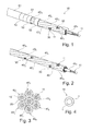
- the microprobe 50 shown on the Figure 1 comprises a plurality of seven microcables 40 1 , 40 2 , 40 3 , 40 4 , 40 5 , 40 6 , 40 7 assembled according to a strand shown more specifically to FIG. Figure 2 , each microcable constituting for the microprobe 50 a conduction line connected to a pole of the generator.
- a microcable comprises a core cable 11 surrounded by an insulation layer 20 so as to electrically isolate the microcables from each other.
- each core cable 11 is formed by a strand of seven elementary strands 10 whose diameter is, for example, 0.033 mm. The diameter of a core cable 11 is then 0.1 mm.
- elementary strands 10 of the type shown in FIG. Figure 4 that is to say comprising a core 1 made of a structuring material such as a stainless steel, a cobalt alloy of the MP35N series, a precious metal, titanium or a NiTi alloy, of high resistance to fatigue, the diameter of 0.033 mm allowing on average to guarantee a breaking strength in maximum fatigue in the extreme conditions of stress to which such structures can be subjected.
- a structuring material such as a stainless steel, a cobalt alloy of the MP35N series, a precious metal, titanium or a NiTi alloy
- radiopaque material 2 In order to guarantee sufficient X-ray visibility for the implantation of the microprobe, it may be necessary to introduce a minimum quantity of radiopaque material 2 along the core cable according to a composite structure that reconciles the fatigue resistance of the cable. and radiopacity, most materials used for their X-ray visibility, namely tantalum (Ta), tungsten (W), iridium (Ir), platinum (Pt) and gold (Au) generally not having a high resistance to fatigue.
- the microprobe has a risk of heating related to currents induced by "skin effect" outside the elementary strands under the action of the applied magnetic field.
- the small diameter given to the strands is favorable to heat dissipation and reduces the heating effects due to MRI.
- the thermal energy stored by the materials already limited in volume, can be further reduced if the unitary strands are coated with an outer layer of low magnetic susceptibility material (the magnetic susceptibility being the faculty of a material to to be magnetized under the action of an external magnetic field).
- the most favorable materials in this application are those whose magnetic susceptibility is less than 2000.10 -12 .m 3 .mole -1 , especially tantalum (Ta), titanium (Ti), rhodium (Rh), molybdenum ( Mo), tungsten (W), palladium (Pd) and gold (Au).
- the thickness of the isolation layer is 0.025 mm (25 ⁇ m). Microcables of 0.150 mm in diameter and a strand of seven microcables with a diameter of 0.45 mm are thus produced.
- the processes for producing the insulation layer 20 on the core cable are, for example, the coextrusion on the conductor or the heating of a heat-shrinkable tube.
- the insulation layers surrounding the core cables 11 of the microcables have at least one stripped area 30 intended to form, according to production methods which will be described in detail below, a detection / stimulation electrode for the microprobe 50, like the electrodes 52 of the Figure 1 .
- the stripped areas 30 are obtained in particular by the laser ablation technique.
- This example takes into account only one electrode at the distal end of the central microcable 40 7 .
- the number of electrodes there is no limitation to the number of electrodes, but for a microprobe consisting of seven stranded microcables, the number of poles is dependent on the number of microcables, here seven poles.
- Another possibility is to electrically connect a plurality of microcables to the same electrical potential, to increase the reliability by this redundancy.
- Figure 3 connect two (or three) of the seven microcables to the same pole of the generator proximal side, and distal side to group the electrodes of these microcables in the same stimulation area to form a specific point of stimulation - or, conversely , to remove them between them several centimeters to create a large area of stimulation.
- FIG. 1 shows more particularly that the microprobe 50 is surrounded by an outer sheath 51, except at the locations occupied by the electrodes 52.
- This sheath 51 may be heat-shrinkable polymer, such as polyethylene terephthalate (PET). Its thickness is typically 0.025 mm (25 ⁇ m), which corresponds to a final diameter of 0.5 mm or 1.5 French for the microprobe 50.
- PET polyethylene terephthalate
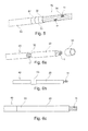
- the Figure 5 illustrates a first embodiment of the microprobe 50 in which conducting rings 52 platinum / iridium 90/10 type respectively placed opposite a stripped area 30 (not visible in the figure). Each ring 52 is fixed by reducing its outer diameter, for example by crimping, until the local contacting of the inner diameter of the ring 52 with the core cable 11 of the stripped microcable.
- the reduction of the diameter of the ring 52, obtained by deformation of material, causes intrinsic constraints on the ring but also on the insulation layers 20 and the core cables 11.
- the material of the rings 52 must therefore be sufficiently malleable so as not to damage the non-bare areas.
- the assembly of the microprobe 50 of the Figure 5 consists in alternately threading a length of heat-shrinkable sheath 51 and a conductive ring 52.
- the electrodes 52 are of the annular type and allow 360 ° stimulation.
- a first ring 53 referred to as an inner ring, also made of iridescent platinum, whose inner diameter is at least equal to the outer diameter of the microcables, ie 0.15 mm, for an outer diameter of 0.18 mm, is threaded on the one of the microcables 40 ( Figure 6a ) to be next to a bare area 30 ( Figure 6b ) and be set ( Figure 6c ) so as to make the electrical contact with the core cable 11 and keep the isodiameter.
- the outer diameter of the inner ring 53 is then 0.15 mm.
- This ring 53 is then used as visible mark ( Figure 7a ), under binocular in a vertical position, to allow the placement ( Figure 7b ) a second ring 52, said outer ring or stimulation, attached to the inner ring 53.
- a hole 521 is formed in the outer ring 52 ( Figure 7c ) to facilitate the orientation and positioning of the rings 52, 53 for a laser welding assembly.
- a particular microcable 40 has a zone 30 free of isolation layer 20 ( Figure 8a ). This stripped zone is covered by a deposit 31 of conductive glue ( Figure 8b ) allowing the mounting and positioning of an outer ring 52 which becomes the stimulation electrode in contact with the tissue ( Figure 8c ).
- the function of the conductive adhesive is to transmit an electric current between the two conductive components and to preserve the integrity of the insulation layers of the adjacent microcables. There is no risk of melting the polymer insulation layers, or to cut or reduce their thickness locally.
- This bonding technique can also be applied to the assembly of an inner ring 53 and an outer ring 52, as described with regard to Figures 7a to 7c .
- the structure located under the glued rings consists of rigid and non-compressible metal strands and insulating layers of flexible and therefore compressible polymer.
- This structure On a microscopic scale, it is possible to define this structure as flexible and can vary in size and in geometry.
- the use of glue makes it possible to compensate for these microscopic deformations by virtue of the intrinsic characteristics of the glue and to introduce a relative flexibility in the assembly of the two rings and to make this attachment less brittle when it is subjected to tensile stresses, bending or twisting.
- the Figure 9 shows a distal electrode 52 disposed at the end of the central microcable 40 7 and made according to one of the preceding embodiments, in particular that involving an inner ring and an outer ring.
- the strength of the structure is provided by an alternation of sheath elements 51 enveloping the strand of the seven microcables.
- the length in this alternation of the outer sheath is greater than the lengths of the gaps.
- This sheath also plays an important role in the manipulation of the microprobe during insertion into the catheter. It also ensures that the distal part is shaped to reduce the risk of moving the microprobe into the veins.
- each stimulation point is oriented angularly and does not allow annular stimulation.
- the surface of an electrode is about 0.314 mm 2 for a length of 1 mm. This low stimulation surface is favorable to the longevity of the battery.
- the Figures 11a and 11b represent a low-consumption dipole, consisting of spiral microcables and each covered, in this case, a heat-shrunk PET sheath.
- a stripped zone 30 of a length corresponding to a turn (360 °) is first produced, which makes it possible to increase the conducting surface of each core cable 11 to an equivalent value. to an annular ring type electrode.
- the conductive surface thus twisted offers a better contact with the tissues of the vein over 360 °.
- This architecture makes it possible to make a microprobe that can be used as a dipole and thus obtain a very small distance between the poles.
- the distance between poles is 0.15 mm, separated by a central microcable 40 7 of constant thickness.
- the position of the two stripped microcables at the periphery may be different in particular by alternating non-consecutive microcables such as sheathed microcable / stripped microcable.
- the advantage of such a device is to create an electric field between two electrodes at a very short distance, of identical surface, of the same material, and being in the same electrolyte, which has the consequence of increasing the intensity of the electric field.
Landscapes
- Health & Medical Sciences (AREA)
- Life Sciences & Earth Sciences (AREA)
- Heart & Thoracic Surgery (AREA)
- General Health & Medical Sciences (AREA)
- Public Health (AREA)
- Biomedical Technology (AREA)
- Engineering & Computer Science (AREA)
- Animal Behavior & Ethology (AREA)
- Veterinary Medicine (AREA)
- Nuclear Medicine, Radiotherapy & Molecular Imaging (AREA)
- Radiology & Medical Imaging (AREA)
- Cardiology (AREA)
- Vascular Medicine (AREA)
- Physics & Mathematics (AREA)
- Biophysics (AREA)
- Pathology (AREA)
- Medical Informatics (AREA)
- Molecular Biology (AREA)
- Surgery (AREA)
- Electrotherapy Devices (AREA)
Applications Claiming Priority (1)
| Application Number | Priority Date | Filing Date | Title |
|---|---|---|---|
| FR1259758 | 2012-10-12 |
Publications (2)
| Publication Number | Publication Date |
|---|---|
| EP2719422A1 true EP2719422A1 (de) | 2014-04-16 |
| EP2719422B1 EP2719422B1 (de) | 2015-02-18 |
Family
ID=47428707
Family Applications (1)
| Application Number | Title | Priority Date | Filing Date |
|---|---|---|---|
| EP13169168.5A Active EP2719422B1 (de) | 2012-10-12 | 2013-05-24 | Implantierbare multipolare Mikrosonde zur Erfassung/Stimulation |
Country Status (3)
| Country | Link |
|---|---|
| US (2) | US10463848B2 (de) |
| EP (1) | EP2719422B1 (de) |
| CN (1) | CN103721342B (de) |
Cited By (6)
| Publication number | Priority date | Publication date | Assignee | Title |
|---|---|---|---|---|
| EP2959828A1 (de) | 2014-06-25 | 2015-12-30 | Sorin CRM SAS | Hybrid-einheit, die eine aktive implantierbare medizinische vorrichtung bildet |
| EP3058983A1 (de) | 2015-02-17 | 2016-08-24 | Sorin CRM SAS | Mikrosonde zur detektion/stimulation, insbesondere für die mehrpunkt-neuromodulation des zentralen nervensystems |
| EP3069755A1 (de) | 2015-03-18 | 2016-09-21 | Sorin CRM SAS | Aktive implantierbare medizinische vorrichtung, die eine kapsel ohne anschluss umfasst, die permanent mit einer mikrosonde verbunden ist |
| WO2017158174A1 (fr) | 2016-03-18 | 2017-09-21 | Sorin Crm Sas | Dispositif médical implantable actif de traitement combiné du rythme cardiaque et du rythme respiratoire |
| WO2017198472A1 (en) | 2016-05-19 | 2017-11-23 | Sorin Crm Sas | Dual multipolar lead implantable in the coronary venous network |
| EP3591763A1 (de) | 2018-07-06 | 2020-01-08 | Sorin CRM SAS | Anschlussverfahren zum anschliessen eines isolierten mikroleiters |
Families Citing this family (10)
| Publication number | Priority date | Publication date | Assignee | Title |
|---|---|---|---|---|
| EP2664354B1 (de) | 2012-05-16 | 2015-09-16 | Sorin CRM SAS | Medizinische Leitung mit einer Ringelektrode zur Implantation in ein Herz- oder Hirngefäß und ein Verfahren zu deren Herstellung |
| US20130310673A1 (en) * | 2012-05-17 | 2013-11-21 | Assaf Govari | Guide wire with position sensing electrodes |
| US9955878B2 (en) * | 2014-02-03 | 2018-05-01 | Volcano Corporation | Intravascular devices, systems, and methods having a core wire with embedded conductors |
| US20170189674A1 (en) * | 2016-01-04 | 2017-07-06 | Medtronic, Inc. | Medical electrical lead |
| EP3542853B1 (de) * | 2018-03-23 | 2021-05-05 | Heraeus Deutschland GmbH & Co. KG | Herstellungsverfahren für eine mikroleitung |
| EP3542854B1 (de) | 2018-03-23 | 2021-06-30 | Heraeus Deutschland GmbH & Co. KG | Herstellungsverfahren für ein multielektrodensystem |
| US11458300B2 (en) | 2018-12-28 | 2022-10-04 | Heraeus Medical Components Llc | Overmolded segmented electrode |
| DE102019218477B4 (de) * | 2019-11-28 | 2022-01-05 | Heraeus Deutschland GmbH & Co. KG | Mikro-Lead für direktionale Stimulation |
| KR102463096B1 (ko) * | 2021-01-19 | 2022-11-03 | 주식회사 페라자 | 다중 헬릭스 연성 메커니즘 |
| CN118541346A (zh) * | 2021-11-08 | 2024-08-23 | 奥纳治疗公司 | 用于递送环状多核苷酸的脂质纳米颗粒组合物 |
Citations (4)
| Publication number | Priority date | Publication date | Assignee | Title |
|---|---|---|---|---|
| US6192280B1 (en) | 1999-06-02 | 2001-02-20 | Medtronic, Inc. | Guidewire placed implantable lead with tip seal |
| US7047082B1 (en) | 1999-09-16 | 2006-05-16 | Micronet Medical, Inc. | Neurostimulating lead |
| EP2384784A1 (de) * | 2010-05-05 | 2011-11-09 | Sorin CRM SAS | Einheit zur endokavitären Stimulation/Defibrillation des linken Herzventrikels |
| EP2455131A1 (de) | 2010-11-19 | 2012-05-23 | Sorin CRM SAS | Sonde zur Stimulation einer linken Herzkammer, die in das Netz der Herzkranzgefäße implantiert werden kann |
Family Cites Families (25)
| Publication number | Priority date | Publication date | Assignee | Title |
|---|---|---|---|---|
| US1691869A (en) * | 1924-07-03 | 1928-11-13 | Frank F Fowle | Electrical conductor |
| US2320470A (en) * | 1938-04-11 | 1943-06-01 | Mackworth G Rees | Current delivering and conducting means |
| JPS60172755A (ja) * | 1984-02-17 | 1985-09-06 | Honda Motor Co Ltd | 車両用変速機の制御装置 |
| JPH066115B2 (ja) * | 1987-08-27 | 1994-01-26 | 新技術事業団 | 生体内埋込用電極 |
| EP0312495A3 (de) * | 1987-10-16 | 1989-08-30 | Institut Straumann Ag | Elektrisches Kabel für die Durchführung mindestens einer Stimulation und/oder Messung in einem menschlichen oder tierischen Körper |
| US4945341A (en) | 1989-04-05 | 1990-07-31 | Buttimer Gregory J | Alarm system for electrical devices |
| US5246014A (en) * | 1991-11-08 | 1993-09-21 | Medtronic, Inc. | Implantable lead system |
| US5760341A (en) * | 1996-09-10 | 1998-06-02 | Medtronic, Inc. | Conductor cable for biomedical lead |
| US6324415B1 (en) * | 1997-07-30 | 2001-11-27 | Intermedics Inc. | Cardiac lead with minimized inside diameter of sleeve |
| US6216045B1 (en) * | 1999-04-26 | 2001-04-10 | Advanced Neuromodulation Systems, Inc. | Implantable lead and method of manufacture |
| US20030236562A1 (en) * | 2000-10-10 | 2003-12-25 | Kuzma Janusz A. | Band type multicontact electrode and method of making the same |
| US7138582B2 (en) * | 2003-06-24 | 2006-11-21 | Medtronic, Inc. | Medical electrical lead conductor formed from modified MP35N alloy |
| US7155294B2 (en) * | 2003-06-26 | 2006-12-26 | Medtronic, Inc. | Conductor arrangement for multipolar medical electrical leads |
| US7420124B2 (en) * | 2004-02-11 | 2008-09-02 | Fort Wayne Metals Research Products Corp. | Drawn strand filled tubing wire |
| EP1849166B1 (de) * | 2004-11-23 | 2016-01-20 | Advanced Neuromodulation Systems, Inc. | Verfahren zur herstellung einer leitung mit mehreren elektroden |
| US20080046059A1 (en) * | 2006-08-04 | 2008-02-21 | Zarembo Paul E | Lead including a heat fused or formed lead body |
| US20080114230A1 (en) * | 2006-11-14 | 2008-05-15 | Bruce Addis | Electrode support |
| US8155756B2 (en) * | 2007-02-16 | 2012-04-10 | Pacesetter, Inc. | Motion-based optimization for placement of cardiac stimulation electrodes |
| US8005550B2 (en) * | 2007-09-13 | 2011-08-23 | Medtronic, Inc. | Medical electrical lead |
| US20110220408A1 (en) * | 2009-02-23 | 2011-09-15 | Walsh Robert G | Electrode and connector attachments for a cylindrical glass fiber wire lead |
| US8364281B2 (en) * | 2008-11-07 | 2013-01-29 | W. L. Gore & Associates, Inc. | Implantable lead |
| US9833616B2 (en) | 2009-01-02 | 2017-12-05 | Medtronic, Inc. | System and method for cardiac lead |
| US20100222860A1 (en) | 2009-03-02 | 2010-09-02 | Pacesetter, Inc. | Implantable Leads Having Mechanisms to Impede Over-Rotation of Fixation Mechanisms |
| US8533944B2 (en) * | 2009-12-07 | 2013-09-17 | Advanced Neuromodulation Systems, Inc. | Method for fabrication of a neurostimulaton lead including multiple micro-cables |
| US8560084B2 (en) * | 2011-08-30 | 2013-10-15 | Greatbatch Ltd. | Lead body with inner and outer co-axial coils |
-
2013
- 2013-05-24 EP EP13169168.5A patent/EP2719422B1/de active Active
- 2013-10-11 US US14/052,371 patent/US10463848B2/en active Active
- 2013-10-12 CN CN201310475838.1A patent/CN103721342B/zh active Active
-
2019
- 2019-10-29 US US16/667,222 patent/US11771889B2/en active Active
Patent Citations (4)
| Publication number | Priority date | Publication date | Assignee | Title |
|---|---|---|---|---|
| US6192280B1 (en) | 1999-06-02 | 2001-02-20 | Medtronic, Inc. | Guidewire placed implantable lead with tip seal |
| US7047082B1 (en) | 1999-09-16 | 2006-05-16 | Micronet Medical, Inc. | Neurostimulating lead |
| EP2384784A1 (de) * | 2010-05-05 | 2011-11-09 | Sorin CRM SAS | Einheit zur endokavitären Stimulation/Defibrillation des linken Herzventrikels |
| EP2455131A1 (de) | 2010-11-19 | 2012-05-23 | Sorin CRM SAS | Sonde zur Stimulation einer linken Herzkammer, die in das Netz der Herzkranzgefäße implantiert werden kann |
Cited By (12)
| Publication number | Priority date | Publication date | Assignee | Title |
|---|---|---|---|---|
| EP2959828A1 (de) | 2014-06-25 | 2015-12-30 | Sorin CRM SAS | Hybrid-einheit, die eine aktive implantierbare medizinische vorrichtung bildet |
| US10099060B2 (en) | 2014-06-25 | 2018-10-16 | Sorin Crm Sas | Hybrid system forming an active implantable medical device |
| US10898722B2 (en) | 2014-06-25 | 2021-01-26 | Sorin Crm Sas | Hybrid system forming an active implantable medical device |
| EP3058983A1 (de) | 2015-02-17 | 2016-08-24 | Sorin CRM SAS | Mikrosonde zur detektion/stimulation, insbesondere für die mehrpunkt-neuromodulation des zentralen nervensystems |
| US9937340B2 (en) | 2015-02-17 | 2018-04-10 | Sorin Crm Sas | Microlead for multipoint neuromodulation of the central nervous system |
| US10183161B2 (en) | 2015-02-17 | 2019-01-22 | Sorin Crm Sas | Microlead for multipoint neuromodulation of the central nervous system |
| EP3069755A1 (de) | 2015-03-18 | 2016-09-21 | Sorin CRM SAS | Aktive implantierbare medizinische vorrichtung, die eine kapsel ohne anschluss umfasst, die permanent mit einer mikrosonde verbunden ist |
| WO2017158174A1 (fr) | 2016-03-18 | 2017-09-21 | Sorin Crm Sas | Dispositif médical implantable actif de traitement combiné du rythme cardiaque et du rythme respiratoire |
| WO2017198472A1 (en) | 2016-05-19 | 2017-11-23 | Sorin Crm Sas | Dual multipolar lead implantable in the coronary venous network |
| US10912938B2 (en) | 2016-05-19 | 2021-02-09 | Sorin Crm Sas | Dual multipolar lead implantable in the coronary venous network |
| US12042650B2 (en) | 2016-05-19 | 2024-07-23 | Sorin Crm Sas | Dual multipolar lead implantable in the coronary venous network |
| EP3591763A1 (de) | 2018-07-06 | 2020-01-08 | Sorin CRM SAS | Anschlussverfahren zum anschliessen eines isolierten mikroleiters |
Also Published As
| Publication number | Publication date |
|---|---|
| EP2719422B1 (de) | 2015-02-18 |
| CN103721342A (zh) | 2014-04-16 |
| US20140107455A1 (en) | 2014-04-17 |
| US10463848B2 (en) | 2019-11-05 |
| US20200061367A1 (en) | 2020-02-27 |
| CN103721342B (zh) | 2018-05-08 |
| US11771889B2 (en) | 2023-10-03 |
Similar Documents
| Publication | Publication Date | Title |
|---|---|---|
| EP2719422B1 (de) | Implantierbare multipolare Mikrosonde zur Erfassung/Stimulation | |
| EP3058983B1 (de) | Mikrosonde zur detektion/stimulation, insbesondere für die mehrpunkt-neuromodulation des zentralen nervensystems | |
| EP4043065A1 (de) | Mikrosonde zur detektion/stimulation, die in venen-, arterien- oder lymphsystem-netze implantiert werden kann | |
| EP2455131B1 (de) | Sonde zur Stimulation einer linken Herzkammer, die in das Netz der Herzkranzgefäße implantiert werden kann | |
| EP2664354B1 (de) | Medizinische Leitung mit einer Ringelektrode zur Implantation in ein Herz- oder Hirngefäß und ein Verfahren zu deren Herstellung | |
| US5016646A (en) | Thin electrode lead and connections | |
| EP2878332B1 (de) | Detektions-/Stimulationsmikrosonde zur Implantation in ein Gefäß des Venen-, Arterien- oder Lymphsystems | |
| AU2004216639A1 (en) | Implantable lead and method of manufacture | |
| EP2572751B1 (de) | Sonde zur Stimulation einer ausgedehnten Zone in einem Hohlraum des Herzens, die per OTW-Katheterführung in das Netz der tiefen Herzkranzgefäße implantiert werden kann | |
| FR2786701A1 (fr) | Systeme a conducteur electrique medical et a dispositif d'introduction, ensemble conducteur pour un tel systeme et son procede de fabrication | |
| WO2011106093A2 (en) | Electrode and connector attachments for a cylindrical glass fiber fine wire lead | |
| EP2682151A1 (de) | Einführbarer mikrokatheter für Venös-, Arteriell- und Lymphatisches System | |
| EP2719423B1 (de) | Atraumatische Mikrosonde zur Erfassung/Stimulation | |
| EP2559453B1 (de) | Leiter zur Implantation in die Herzkranzgefäße zur mehrzonigen Stimulation eines linken Herzraums | |
| JP2011500209A (ja) | 非コイル状のワイヤ構造物を備えた刺激用および検知用リード線 | |
| EP2732848B1 (de) | Mikroleiter zur implantation in die tiefen herzkranzgefässe mit einem verformbaren proximalen teil | |
| EP3542854B1 (de) | Herstellungsverfahren für ein multielektrodensystem | |
| US20100331941A1 (en) | Implantable fine wire lead for electrostimulation and sensing | |
| EP2810686B1 (de) | Einheit zum Implantieren in den koronaren Venenkreislauf zur Stimulation einer linken Herzhöhle |
Legal Events
| Date | Code | Title | Description |
|---|---|---|---|
| PUAI | Public reference made under article 153(3) epc to a published international application that has entered the european phase |
Free format text: ORIGINAL CODE: 0009012 |
|
| AK | Designated contracting states |
Kind code of ref document: A1 Designated state(s): AL AT BE BG CH CY CZ DE DK EE ES FI FR GB GR HR HU IE IS IT LI LT LU LV MC MK MT NL NO PL PT RO RS SE SI SK SM TR |
|
| AX | Request for extension of the european patent |
Extension state: BA ME |
|
| 17P | Request for examination filed |
Effective date: 20140929 |
|
| GRAP | Despatch of communication of intention to grant a patent |
Free format text: ORIGINAL CODE: EPIDOSNIGR1 |
|
| RBV | Designated contracting states (corrected) |
Designated state(s): AL AT BE BG CH CY CZ DE DK EE ES FI FR GB GR HR HU IE IS IT LI LT LU LV MC MK MT NL NO PL PT RO RS SE SI SK SM TR |
|
| RIC1 | Information provided on ipc code assigned before grant |
Ipc: A61N 1/05 20060101AFI20141020BHEP |
|
| INTG | Intention to grant announced |
Effective date: 20141105 |
|
| RIN1 | Information on inventor provided before grant (corrected) |
Inventor name: D'HIVER, PHILIPPE Inventor name: REGNIER, WILLY Inventor name: SHAN, NICHOLAS Inventor name: OLLIVIER, JEAN-FRANCOIS |
|
| GRAS | Grant fee paid |
Free format text: ORIGINAL CODE: EPIDOSNIGR3 |
|
| GRAA | (expected) grant |
Free format text: ORIGINAL CODE: 0009210 |
|
| AK | Designated contracting states |
Kind code of ref document: B1 Designated state(s): AL AT BE BG CH CY CZ DE DK EE ES FI FR GB GR HR HU IE IS IT LI LT LU LV MC MK MT NL NO PL PT RO RS SE SI SK SM TR |
|
| REG | Reference to a national code |
Ref country code: GB Ref legal event code: FG4D Free format text: NOT ENGLISH |
|
| REG | Reference to a national code |
Ref country code: CH Ref legal event code: EP |
|
| REG | Reference to a national code |
Ref country code: AT Ref legal event code: REF Ref document number: 710396 Country of ref document: AT Kind code of ref document: T Effective date: 20150315 |
|
| REG | Reference to a national code |
Ref country code: IE Ref legal event code: FG4D Free format text: LANGUAGE OF EP DOCUMENT: FRENCH |
|
| REG | Reference to a national code |
Ref country code: DE Ref legal event code: R096 Ref document number: 602013000979 Country of ref document: DE Effective date: 20150402 |
|
| REG | Reference to a national code |
Ref country code: FR Ref legal event code: PLFP Year of fee payment: 3 |
|
| REG | Reference to a national code |
Ref country code: NL Ref legal event code: VDEP Effective date: 20150218 |
|
| REG | Reference to a national code |
Ref country code: AT Ref legal event code: MK05 Ref document number: 710396 Country of ref document: AT Kind code of ref document: T Effective date: 20150218 |
|
| REG | Reference to a national code |
Ref country code: LT Ref legal event code: MG4D |
|
| PG25 | Lapsed in a contracting state [announced via postgrant information from national office to epo] |
Ref country code: ES Free format text: LAPSE BECAUSE OF FAILURE TO SUBMIT A TRANSLATION OF THE DESCRIPTION OR TO PAY THE FEE WITHIN THE PRESCRIBED TIME-LIMIT Effective date: 20150218 Ref country code: FI Free format text: LAPSE BECAUSE OF FAILURE TO SUBMIT A TRANSLATION OF THE DESCRIPTION OR TO PAY THE FEE WITHIN THE PRESCRIBED TIME-LIMIT Effective date: 20150218 Ref country code: SE Free format text: LAPSE BECAUSE OF FAILURE TO SUBMIT A TRANSLATION OF THE DESCRIPTION OR TO PAY THE FEE WITHIN THE PRESCRIBED TIME-LIMIT Effective date: 20150218 Ref country code: HR Free format text: LAPSE BECAUSE OF FAILURE TO SUBMIT A TRANSLATION OF THE DESCRIPTION OR TO PAY THE FEE WITHIN THE PRESCRIBED TIME-LIMIT Effective date: 20150218 Ref country code: NO Free format text: LAPSE BECAUSE OF FAILURE TO SUBMIT A TRANSLATION OF THE DESCRIPTION OR TO PAY THE FEE WITHIN THE PRESCRIBED TIME-LIMIT Effective date: 20150518 Ref country code: LT Free format text: LAPSE BECAUSE OF FAILURE TO SUBMIT A TRANSLATION OF THE DESCRIPTION OR TO PAY THE FEE WITHIN THE PRESCRIBED TIME-LIMIT Effective date: 20150218 |
|
| PG25 | Lapsed in a contracting state [announced via postgrant information from national office to epo] |
Ref country code: AT Free format text: LAPSE BECAUSE OF FAILURE TO SUBMIT A TRANSLATION OF THE DESCRIPTION OR TO PAY THE FEE WITHIN THE PRESCRIBED TIME-LIMIT Effective date: 20150218 Ref country code: RS Free format text: LAPSE BECAUSE OF FAILURE TO SUBMIT A TRANSLATION OF THE DESCRIPTION OR TO PAY THE FEE WITHIN THE PRESCRIBED TIME-LIMIT Effective date: 20150218 Ref country code: GR Free format text: LAPSE BECAUSE OF FAILURE TO SUBMIT A TRANSLATION OF THE DESCRIPTION OR TO PAY THE FEE WITHIN THE PRESCRIBED TIME-LIMIT Effective date: 20150519 Ref country code: LV Free format text: LAPSE BECAUSE OF FAILURE TO SUBMIT A TRANSLATION OF THE DESCRIPTION OR TO PAY THE FEE WITHIN THE PRESCRIBED TIME-LIMIT Effective date: 20150218 Ref country code: IS Free format text: LAPSE BECAUSE OF FAILURE TO SUBMIT A TRANSLATION OF THE DESCRIPTION OR TO PAY THE FEE WITHIN THE PRESCRIBED TIME-LIMIT Effective date: 20150618 Ref country code: NL Free format text: LAPSE BECAUSE OF FAILURE TO SUBMIT A TRANSLATION OF THE DESCRIPTION OR TO PAY THE FEE WITHIN THE PRESCRIBED TIME-LIMIT Effective date: 20150218 |
|
| PG25 | Lapsed in a contracting state [announced via postgrant information from national office to epo] |
Ref country code: CZ Free format text: LAPSE BECAUSE OF FAILURE TO SUBMIT A TRANSLATION OF THE DESCRIPTION OR TO PAY THE FEE WITHIN THE PRESCRIBED TIME-LIMIT Effective date: 20150218 Ref country code: RO Free format text: LAPSE BECAUSE OF FAILURE TO SUBMIT A TRANSLATION OF THE DESCRIPTION OR TO PAY THE FEE WITHIN THE PRESCRIBED TIME-LIMIT Effective date: 20150218 Ref country code: SK Free format text: LAPSE BECAUSE OF FAILURE TO SUBMIT A TRANSLATION OF THE DESCRIPTION OR TO PAY THE FEE WITHIN THE PRESCRIBED TIME-LIMIT Effective date: 20150218 Ref country code: DK Free format text: LAPSE BECAUSE OF FAILURE TO SUBMIT A TRANSLATION OF THE DESCRIPTION OR TO PAY THE FEE WITHIN THE PRESCRIBED TIME-LIMIT Effective date: 20150218 Ref country code: EE Free format text: LAPSE BECAUSE OF FAILURE TO SUBMIT A TRANSLATION OF THE DESCRIPTION OR TO PAY THE FEE WITHIN THE PRESCRIBED TIME-LIMIT Effective date: 20150218 |
|
| REG | Reference to a national code |
Ref country code: DE Ref legal event code: R097 Ref document number: 602013000979 Country of ref document: DE |
|
| PG25 | Lapsed in a contracting state [announced via postgrant information from national office to epo] |
Ref country code: PL Free format text: LAPSE BECAUSE OF FAILURE TO SUBMIT A TRANSLATION OF THE DESCRIPTION OR TO PAY THE FEE WITHIN THE PRESCRIBED TIME-LIMIT Effective date: 20150218 |
|
| PLBE | No opposition filed within time limit |
Free format text: ORIGINAL CODE: 0009261 |
|
| STAA | Information on the status of an ep patent application or granted ep patent |
Free format text: STATUS: NO OPPOSITION FILED WITHIN TIME LIMIT |
|
| 26N | No opposition filed |
Effective date: 20151119 |
|
| PG25 | Lapsed in a contracting state [announced via postgrant information from national office to epo] |
Ref country code: LU Free format text: LAPSE BECAUSE OF FAILURE TO SUBMIT A TRANSLATION OF THE DESCRIPTION OR TO PAY THE FEE WITHIN THE PRESCRIBED TIME-LIMIT Effective date: 20150524 Ref country code: MC Free format text: LAPSE BECAUSE OF FAILURE TO SUBMIT A TRANSLATION OF THE DESCRIPTION OR TO PAY THE FEE WITHIN THE PRESCRIBED TIME-LIMIT Effective date: 20150218 |
|
| REG | Reference to a national code |
Ref country code: IE Ref legal event code: MM4A |
|
| PG25 | Lapsed in a contracting state [announced via postgrant information from national office to epo] |
Ref country code: SI Free format text: LAPSE BECAUSE OF FAILURE TO SUBMIT A TRANSLATION OF THE DESCRIPTION OR TO PAY THE FEE WITHIN THE PRESCRIBED TIME-LIMIT Effective date: 20150218 |
|
| REG | Reference to a national code |
Ref country code: FR Ref legal event code: PLFP Year of fee payment: 4 |
|
| PG25 | Lapsed in a contracting state [announced via postgrant information from national office to epo] |
Ref country code: IE Free format text: LAPSE BECAUSE OF NON-PAYMENT OF DUE FEES Effective date: 20150524 |
|
| PG25 | Lapsed in a contracting state [announced via postgrant information from national office to epo] |
Ref country code: MT Free format text: LAPSE BECAUSE OF FAILURE TO SUBMIT A TRANSLATION OF THE DESCRIPTION OR TO PAY THE FEE WITHIN THE PRESCRIBED TIME-LIMIT Effective date: 20150218 |
|
| REG | Reference to a national code |
Ref country code: CH Ref legal event code: PL |
|
| PG25 | Lapsed in a contracting state [announced via postgrant information from national office to epo] |
Ref country code: CH Free format text: LAPSE BECAUSE OF NON-PAYMENT OF DUE FEES Effective date: 20160531 Ref country code: LI Free format text: LAPSE BECAUSE OF NON-PAYMENT OF DUE FEES Effective date: 20160531 |
|
| REG | Reference to a national code |
Ref country code: FR Ref legal event code: PLFP Year of fee payment: 5 |
|
| PG25 | Lapsed in a contracting state [announced via postgrant information from national office to epo] |
Ref country code: BG Free format text: LAPSE BECAUSE OF FAILURE TO SUBMIT A TRANSLATION OF THE DESCRIPTION OR TO PAY THE FEE WITHIN THE PRESCRIBED TIME-LIMIT Effective date: 20150218 Ref country code: HU Free format text: LAPSE BECAUSE OF FAILURE TO SUBMIT A TRANSLATION OF THE DESCRIPTION OR TO PAY THE FEE WITHIN THE PRESCRIBED TIME-LIMIT; INVALID AB INITIO Effective date: 20130524 |
|
| PG25 | Lapsed in a contracting state [announced via postgrant information from national office to epo] |
Ref country code: CY Free format text: LAPSE BECAUSE OF FAILURE TO SUBMIT A TRANSLATION OF THE DESCRIPTION OR TO PAY THE FEE WITHIN THE PRESCRIBED TIME-LIMIT Effective date: 20150218 |
|
| PG25 | Lapsed in a contracting state [announced via postgrant information from national office to epo] |
Ref country code: BE Free format text: LAPSE BECAUSE OF NON-PAYMENT OF DUE FEES Effective date: 20150531 |
|
| PG25 | Lapsed in a contracting state [announced via postgrant information from national office to epo] |
Ref country code: TR Free format text: LAPSE BECAUSE OF FAILURE TO SUBMIT A TRANSLATION OF THE DESCRIPTION OR TO PAY THE FEE WITHIN THE PRESCRIBED TIME-LIMIT Effective date: 20150218 |
|
| REG | Reference to a national code |
Ref country code: FR Ref legal event code: PLFP Year of fee payment: 6 |
|
| PG25 | Lapsed in a contracting state [announced via postgrant information from national office to epo] |
Ref country code: SM Free format text: LAPSE BECAUSE OF FAILURE TO SUBMIT A TRANSLATION OF THE DESCRIPTION OR TO PAY THE FEE WITHIN THE PRESCRIBED TIME-LIMIT Effective date: 20150218 |
|
| PG25 | Lapsed in a contracting state [announced via postgrant information from national office to epo] |
Ref country code: MK Free format text: LAPSE BECAUSE OF FAILURE TO SUBMIT A TRANSLATION OF THE DESCRIPTION OR TO PAY THE FEE WITHIN THE PRESCRIBED TIME-LIMIT Effective date: 20150218 Ref country code: PT Free format text: LAPSE BECAUSE OF FAILURE TO SUBMIT A TRANSLATION OF THE DESCRIPTION OR TO PAY THE FEE WITHIN THE PRESCRIBED TIME-LIMIT Effective date: 20150218 |
|
| PG25 | Lapsed in a contracting state [announced via postgrant information from national office to epo] |
Ref country code: AL Free format text: LAPSE BECAUSE OF FAILURE TO SUBMIT A TRANSLATION OF THE DESCRIPTION OR TO PAY THE FEE WITHIN THE PRESCRIBED TIME-LIMIT Effective date: 20150218 |
|
| P01 | Opt-out of the competence of the unified patent court (upc) registered |
Effective date: 20230714 |
|
| PGFP | Annual fee paid to national office [announced via postgrant information from national office to epo] |
Ref country code: GB Payment date: 20240523 Year of fee payment: 12 |
|
| PGFP | Annual fee paid to national office [announced via postgrant information from national office to epo] |
Ref country code: DE Payment date: 20240513 Year of fee payment: 12 |
|
| PGFP | Annual fee paid to national office [announced via postgrant information from national office to epo] |
Ref country code: IT Payment date: 20240513 Year of fee payment: 12 Ref country code: FR Payment date: 20240524 Year of fee payment: 12 |