EP3058983B1 - Mikrosonde zur detektion/stimulation, insbesondere für die mehrpunkt-neuromodulation des zentralen nervensystems - Google Patents
Mikrosonde zur detektion/stimulation, insbesondere für die mehrpunkt-neuromodulation des zentralen nervensystems Download PDFInfo
- Publication number
- EP3058983B1 EP3058983B1 EP16154603.1A EP16154603A EP3058983B1 EP 3058983 B1 EP3058983 B1 EP 3058983B1 EP 16154603 A EP16154603 A EP 16154603A EP 3058983 B1 EP3058983 B1 EP 3058983B1
- Authority
- EP
- European Patent Office
- Prior art keywords
- microprobe
- support structure
- central support
- diameter
- layer
- Prior art date
- Legal status (The legal status is an assumption and is not a legal conclusion. Google has not performed a legal analysis and makes no representation as to the accuracy of the status listed.)
- Active
Links
- 230000000638 stimulation Effects 0.000 title claims description 18
- 238000001514 detection method Methods 0.000 title claims description 6
- 230000004007 neuromodulation Effects 0.000 title description 6
- 210000003169 central nervous system Anatomy 0.000 title description 4
- 239000004020 conductor Substances 0.000 claims description 29
- 230000002093 peripheral effect Effects 0.000 claims description 13
- 238000002513 implantation Methods 0.000 claims description 11
- 230000002490 cerebral effect Effects 0.000 claims description 9
- 238000009413 insulation Methods 0.000 claims description 6
- 238000004804 winding Methods 0.000 claims description 6
- 238000005452 bending Methods 0.000 claims description 5
- 239000007787 solid Substances 0.000 claims description 5
- 230000007704 transition Effects 0.000 claims description 4
- 230000005489 elastic deformation Effects 0.000 claims description 3
- 230000003247 decreasing effect Effects 0.000 claims description 2
- WABPQHHGFIMREM-UHFFFAOYSA-N lead(0) Chemical compound [Pb] WABPQHHGFIMREM-UHFFFAOYSA-N 0.000 claims 5
- 239000000523 sample Substances 0.000 description 19
- 210000004556 brain Anatomy 0.000 description 12
- 238000000034 method Methods 0.000 description 11
- 230000000694 effects Effects 0.000 description 7
- 239000000463 material Substances 0.000 description 7
- KDLHZDBZIXYQEI-UHFFFAOYSA-N Palladium Chemical compound [Pd] KDLHZDBZIXYQEI-UHFFFAOYSA-N 0.000 description 4
- 239000004696 Poly ether ether ketone Substances 0.000 description 4
- 239000004952 Polyamide Substances 0.000 description 4
- 229920002647 polyamide Polymers 0.000 description 4
- 229920000728 polyester Polymers 0.000 description 4
- 229920002530 polyetherether ketone Polymers 0.000 description 4
- 229920002635 polyurethane Polymers 0.000 description 4
- 239000004814 polyurethane Substances 0.000 description 4
- 238000013459 approach Methods 0.000 description 3
- 230000006870 function Effects 0.000 description 3
- 230000007383 nerve stimulation Effects 0.000 description 3
- 201000008450 Intracranial aneurysm Diseases 0.000 description 2
- 208000018737 Parkinson disease Diseases 0.000 description 2
- 229910000566 Platinum-iridium alloy Inorganic materials 0.000 description 2
- 229920002614 Polyether block amide Polymers 0.000 description 2
- 208000027418 Wounds and injury Diseases 0.000 description 2
- 206010015037 epilepsy Diseases 0.000 description 2
- 229920000840 ethylene tetrafluoroethylene copolymer Polymers 0.000 description 2
- 229920002313 fluoropolymer Polymers 0.000 description 2
- 239000004811 fluoropolymer Substances 0.000 description 2
- 238000010348 incorporation Methods 0.000 description 2
- 238000003780 insertion Methods 0.000 description 2
- 230000037431 insertion Effects 0.000 description 2
- 230000007774 longterm Effects 0.000 description 2
- 229910052751 metal Inorganic materials 0.000 description 2
- 239000002184 metal Substances 0.000 description 2
- 210000003205 muscle Anatomy 0.000 description 2
- 230000000926 neurological effect Effects 0.000 description 2
- 229910052763 palladium Inorganic materials 0.000 description 2
- 230000007170 pathology Effects 0.000 description 2
- VPRUMANMDWQMNF-UHFFFAOYSA-N phenylethane boronic acid Chemical compound OB(O)CCC1=CC=CC=C1 VPRUMANMDWQMNF-UHFFFAOYSA-N 0.000 description 2
- HWLDNSXPUQTBOD-UHFFFAOYSA-N platinum-iridium alloy Chemical class [Ir].[Pt] HWLDNSXPUQTBOD-UHFFFAOYSA-N 0.000 description 2
- 229920003229 poly(methyl methacrylate) Polymers 0.000 description 2
- 229920000052 poly(p-xylylene) Polymers 0.000 description 2
- 239000004417 polycarbonate Substances 0.000 description 2
- 229920000515 polycarbonate Polymers 0.000 description 2
- 239000004926 polymethyl methacrylate Substances 0.000 description 2
- 229920001343 polytetrafluoroethylene Polymers 0.000 description 2
- 239000004810 polytetrafluoroethylene Substances 0.000 description 2
- 210000000278 spinal cord Anatomy 0.000 description 2
- 210000004281 subthalamic nucleus Anatomy 0.000 description 2
- GUVRBAGPIYLISA-UHFFFAOYSA-N tantalum atom Chemical compound [Ta] GUVRBAGPIYLISA-UHFFFAOYSA-N 0.000 description 2
- 238000012360 testing method Methods 0.000 description 2
- 210000001186 vagus nerve Anatomy 0.000 description 2
- 230000002792 vascular Effects 0.000 description 2
- BQCIDUSAKPWEOX-UHFFFAOYSA-N 1,1-Difluoroethene Chemical compound FC(F)=C BQCIDUSAKPWEOX-UHFFFAOYSA-N 0.000 description 1
- OKTJSMMVPCPJKN-UHFFFAOYSA-N Carbon Chemical compound [C] OKTJSMMVPCPJKN-UHFFFAOYSA-N 0.000 description 1
- 241001415961 Gaviidae Species 0.000 description 1
- 208000012902 Nervous system disease Diseases 0.000 description 1
- 208000025966 Neurological disease Diseases 0.000 description 1
- 239000002033 PVDF binder Substances 0.000 description 1
- 229920001774 Perfluoroether Polymers 0.000 description 1
- 239000004642 Polyimide Substances 0.000 description 1
- 229910000831 Steel Inorganic materials 0.000 description 1
- 241000897276 Termes Species 0.000 description 1
- 210000000577 adipose tissue Anatomy 0.000 description 1
- 230000005540 biological transmission Effects 0.000 description 1
- 239000002041 carbon nanotube Substances 0.000 description 1
- 229910021393 carbon nanotube Inorganic materials 0.000 description 1
- 229920006026 co-polymeric resin Polymers 0.000 description 1
- 239000011248 coating agent Substances 0.000 description 1
- 238000000576 coating method Methods 0.000 description 1
- 238000005516 engineering process Methods 0.000 description 1
- QHSJIZLJUFMIFP-UHFFFAOYSA-N ethene;1,1,2,2-tetrafluoroethene Chemical group C=C.FC(F)=C(F)F QHSJIZLJUFMIFP-UHFFFAOYSA-N 0.000 description 1
- 230000001747 exhibiting effect Effects 0.000 description 1
- PCHJSUWPFVWCPO-UHFFFAOYSA-N gold Chemical compound [Au] PCHJSUWPFVWCPO-UHFFFAOYSA-N 0.000 description 1
- 229910052737 gold Inorganic materials 0.000 description 1
- 239000010931 gold Substances 0.000 description 1
- HCDGVLDPFQMKDK-UHFFFAOYSA-N hexafluoropropylene Chemical group FC(F)=C(F)C(F)(F)F HCDGVLDPFQMKDK-UHFFFAOYSA-N 0.000 description 1
- 208000014674 injury Diseases 0.000 description 1
- 238000009434 installation Methods 0.000 description 1
- 229910052741 iridium Inorganic materials 0.000 description 1
- 210000005240 left ventricle Anatomy 0.000 description 1
- 210000004165 myocardium Anatomy 0.000 description 1
- 210000005036 nerve Anatomy 0.000 description 1
- HLXZNVUGXRDIFK-UHFFFAOYSA-N nickel titanium Chemical compound [Ti].[Ti].[Ti].[Ti].[Ti].[Ti].[Ti].[Ti].[Ti].[Ti].[Ti].[Ni].[Ni].[Ni].[Ni].[Ni].[Ni].[Ni].[Ni].[Ni].[Ni].[Ni].[Ni].[Ni].[Ni] HLXZNVUGXRDIFK-UHFFFAOYSA-N 0.000 description 1
- 229910001000 nickel titanium Inorganic materials 0.000 description 1
- 210000000578 peripheral nerve Anatomy 0.000 description 1
- 210000001428 peripheral nervous system Anatomy 0.000 description 1
- 229920001721 polyimide Polymers 0.000 description 1
- 229920000642 polymer Polymers 0.000 description 1
- -1 polytetrafluoroethylene Polymers 0.000 description 1
- 125000004805 propylene group Chemical group [H]C([H])([H])C([H])([*:1])C([H])([H])[*:2] 0.000 description 1
- 210000003625 skull Anatomy 0.000 description 1
- 230000003068 static effect Effects 0.000 description 1
- 239000010959 steel Substances 0.000 description 1
- 230000004936 stimulating effect Effects 0.000 description 1
- 239000000126 substance Substances 0.000 description 1
- 238000001356 surgical procedure Methods 0.000 description 1
- 229910052715 tantalum Inorganic materials 0.000 description 1
- BFKJFAAPBSQJPD-UHFFFAOYSA-N tetrafluoroethene Chemical group FC(F)=C(F)F BFKJFAAPBSQJPD-UHFFFAOYSA-N 0.000 description 1
- 230000008733 trauma Effects 0.000 description 1
Images

Classifications
-
- A—HUMAN NECESSITIES
- A61—MEDICAL OR VETERINARY SCIENCE; HYGIENE
- A61N—ELECTROTHERAPY; MAGNETOTHERAPY; RADIATION THERAPY; ULTRASOUND THERAPY
- A61N1/00—Electrotherapy; Circuits therefor
- A61N1/02—Details
- A61N1/04—Electrodes
- A61N1/05—Electrodes for implantation or insertion into the body, e.g. heart electrode
- A61N1/0551—Spinal or peripheral nerve electrodes
-
- A—HUMAN NECESSITIES
- A61—MEDICAL OR VETERINARY SCIENCE; HYGIENE
- A61N—ELECTROTHERAPY; MAGNETOTHERAPY; RADIATION THERAPY; ULTRASOUND THERAPY
- A61N1/00—Electrotherapy; Circuits therefor
- A61N1/02—Details
- A61N1/04—Electrodes
- A61N1/05—Electrodes for implantation or insertion into the body, e.g. heart electrode
- A61N1/0526—Head electrodes
- A61N1/0529—Electrodes for brain stimulation
-
- A—HUMAN NECESSITIES
- A61—MEDICAL OR VETERINARY SCIENCE; HYGIENE
- A61N—ELECTROTHERAPY; MAGNETOTHERAPY; RADIATION THERAPY; ULTRASOUND THERAPY
- A61N1/00—Electrotherapy; Circuits therefor
- A61N1/18—Applying electric currents by contact electrodes
- A61N1/32—Applying electric currents by contact electrodes alternating or intermittent currents
- A61N1/36—Applying electric currents by contact electrodes alternating or intermittent currents for stimulation
- A61N1/3605—Implantable neurostimulators for stimulating central or peripheral nerve system
- A61N1/3606—Implantable neurostimulators for stimulating central or peripheral nerve system adapted for a particular treatment
- A61N1/36064—Epilepsy
-
- A—HUMAN NECESSITIES
- A61—MEDICAL OR VETERINARY SCIENCE; HYGIENE
- A61N—ELECTROTHERAPY; MAGNETOTHERAPY; RADIATION THERAPY; ULTRASOUND THERAPY
- A61N1/00—Electrotherapy; Circuits therefor
- A61N1/18—Applying electric currents by contact electrodes
- A61N1/32—Applying electric currents by contact electrodes alternating or intermittent currents
- A61N1/36—Applying electric currents by contact electrodes alternating or intermittent currents for stimulation
- A61N1/3605—Implantable neurostimulators for stimulating central or peripheral nerve system
- A61N1/3606—Implantable neurostimulators for stimulating central or peripheral nerve system adapted for a particular treatment
- A61N1/36067—Movement disorders, e.g. tremor or Parkinson disease
-
- A—HUMAN NECESSITIES
- A61—MEDICAL OR VETERINARY SCIENCE; HYGIENE
- A61N—ELECTROTHERAPY; MAGNETOTHERAPY; RADIATION THERAPY; ULTRASOUND THERAPY
- A61N1/00—Electrotherapy; Circuits therefor
- A61N1/18—Applying electric currents by contact electrodes
- A61N1/32—Applying electric currents by contact electrodes alternating or intermittent currents
- A61N1/36—Applying electric currents by contact electrodes alternating or intermittent currents for stimulation
- A61N1/3605—Implantable neurostimulators for stimulating central or peripheral nerve system
- A61N1/3606—Implantable neurostimulators for stimulating central or peripheral nerve system adapted for a particular treatment
- A61N1/36071—Pain
-
- A—HUMAN NECESSITIES
- A61—MEDICAL OR VETERINARY SCIENCE; HYGIENE
- A61N—ELECTROTHERAPY; MAGNETOTHERAPY; RADIATION THERAPY; ULTRASOUND THERAPY
- A61N1/00—Electrotherapy; Circuits therefor
- A61N1/02—Details
- A61N1/08—Arrangements or circuits for monitoring, protecting, controlling or indicating
- A61N1/086—Magnetic resonance imaging [MRI] compatible leads
Definitions
- the invention relates to “active implantable medical devices” as defined by Directive 90/385 / EEC of June 20, 1990 of the Council of the European Communities.
- It relates more precisely to a neuromodulation microprobe operating by multipoint stimulation of the central nervous system.
- Such a probe is typically intended to be implanted in the cerebral venous network so as to reach specific target areas of the brain in order to apply electrical neurostimulation impulses thereto to treat certain pathologies such as Parkinson's disease, epilepsy, etc. ., techniques grouped under the general name DBS ( Deep Brain Stimulation ). It may also involve stimulating the spinal cord, in particular for the treatment of pain, these techniques being known under the general name SCS ( Spinal Cord Stimulation ).
- DBS Deep Brain Stimulation
- SCS Spinal Cord Stimulation
- VNS Vagus Nerve Stimulation, vagus nerve stimulation
- the specificity of the probes for the stimulation of the central nervous system results mainly in the diameter of these probes, imperatively less than 1.5 French, or 0.5 mm (hence the term "microprobe"), as well as in the number electrodes needed to allow "multipoint" stimulation.
- the aim of the present invention is to provide a microprobe structure which makes it possible to reach deep areas of the brain such as regions, potentially known to be effective for treatment by neuromodulation, known as the subthalamic nucleus (STN) or globus. internal pallidus (GPI), and to stimulate very precisely target areas located in these regions.
- STN subthalamic nucleus
- GPI internal pallidus
- probes of too large a diameter can cause significant neurological damage during implantation surgery. It is therefore necessary to greatly reduce the diameter of the microprobe, but while still retaining excellent seaworthiness properties within the venous network to allow its placement.
- the cerebral arterial venous network indeed comprises strong tortuosities and numerous branches, and it is essential to avoid traumas that could generate a too rigid probe.
- a too flexible microprobe would be difficult to set up, because of too little torsional stiffness to allow the transmission over the entire length of the probe body, to the distal end, of a movement. rotation imprinted from the proximal end (lack of "torquability").
- a too flexible microprobe could not progress in the biological network without bracing under the effect of an axial thrust (lack of "pushability").
- the implantable probe be compatible with 1.6 French (0.53 mm) catheters such as those already used today in interventional neuroradiology, for example for the release of devices such as springs ( coils ) during the treatment of intracranial aneurysms. This imperatively implies for the probe an overall diameter of less than 1.5 French (0.5 mm).
- the electrodes of a neurostimulation microprobe must have an extremely small surface area, so as to be able to precisely stimulate the target areas without risking producing any effects. severe psychiatric secondary education, which unfortunately occurs today in a significant percentage of interventions.
- the US 2006/0089697 A1 describes a probe comprising a plurality of independent wound conductors, distributed around a hollow tube, the assembly being protected by an external insulating sleeve.
- the tube is crossed right through by a central lumen intended to allow the insertion of a delivery mandrel inserted into this lumen during implantation.
- the overall diameter of this structure (at least 0.8 mm) is, however, much too large to reach the deepest target areas of the brain.
- the US 2013/0018445 A1 describes a neurostimulation probe capable of comprising up to 49 conductive strands wound in a spiral and individually insulated, but in an application of stimulation of a peripheral nerve located in muscle or adipose tissue, therefore in an environment where the constraints do not arise very small diameter and seaworthy.
- the EP 2 581 107 A1 and EP 2 719 422 A1 (Sorin CRM) describe structures of microprobes implantable in venous and arterial networks or lymphatics. These microprobes are however essentially designed for implantation in the coronary venous network for the stimulation of the left ventricle of the myocardium, therefore in cardiological applications. Their structure is in fact specifically designed to withstand the very severe fatigue stresses associated with heart beats, which fatigue the material under the effect of repeated flexures over hundreds of millions of cycles, which can cause it to break and limit its duration. life.
- the invention provides a microprobe of the general type disclosed for example by EP 2 719 422 A1 supra, i.e. a multipolar microprobe with an overall diameter of less than 1.5 French (0.5mm) comprising a plurality of at least eight individually insulated conductive wires twisted together, each conductor wire comprising: an electrically conductive core microcable, able to be partially connected proximal to a pole of a generator of an active implantable medical device; and an insulating layer surrounding the core cable, and having at least one stripped area formed in the thickness of the partially distal insulating layer to form a detection / stimulation electrode of the microprobe.
- a microprobe of the general type disclosed for example by EP 2 719 422 A1 supra, i.e. a multipolar microprobe with an overall diameter of less than 1.5 French (0.5mm) comprising a plurality of at least eight individually insulated conductive wires twisted together, each conductor wire comprising: an electrically conductive core microcable, able to be partially
- the microprobe further comprises a central support structure in the form of a surface of revolution, this central support structure being devoid of i) conductive wire and ii) central light, and the conductive wires of said plurality are configured as a layer of a twisted winding of peripheral conductive wires carried by the central support structure and circumferentially distributed thereon.
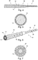
- FIG. 1 there is generally illustrated a microprobe 10 according to the invention, implanted in the cerebral vascular network in order to be able to selectively stimulate deep areas of the brain by localized application of electrical impulses.
- the electrodes of this microprobe can also function, where appropriate, as detection electrodes to collect locally produced electrical potentials.
- Stimulation of target areas of the brain makes it possible in particular to implement neuromodulation techniques intended to treat pathologies such as Parkinson's disease, epilepsy and other neurological diseases.
- the stimulation microprobes that can be envisaged for this purpose must not only be very robust, in order to guarantee long-term biostability (these microprobes are intended to be permanently implanted), but also a very small size, with an overall diameter. less than 1.5 French (0.5 mm). In particular, 1.5 French microprobes would be advantageously compatible with 1.6 French (0.53 mm) catheters, already used today in interventional neuroradiology, for example for the release of devices such as springs (coils) when treating intracranial aneurysms.
- these microprobes must have a large number of electrodes, typically 20 to 100 electrodes, independently selectable so as to be able to choose the stimulation zones very precisely as a function of the desired effect. It is also desirable to be able to choose the axial direction in which these electrodes act, in order to optimize the effect produced and to avoid the appearance of undesirable side effects.
- FIGS. 2a and 2b show, respectively in cross section and in side view, the microprobe structure proposed by the present invention.
- the microprobe 10 comprises a central support structure 12 in the form of a surface of revolution, covered at its periphery with a plurality of peripheral conductive wires 14 carried by this central support structure 12 and circumferentially distributed thereon.
- Each of the peripheral conductor wires 14 includes an electrically conductive core microcable 16 and an insulation layer 18 surrounding the core cable.
- the core microcable can be made of a conductive metal such as platinum-iridium alloy, MP35N steel, nitinol, etc.
- a conductive metal such as platinum-iridium alloy, MP35N steel, nitinol, etc.
- Various core cable structures suitable for this application are described in particular in EP 2 581 107 A1 cited above (Sorin CRM), to which reference may be made for more details.
- the core microcable 16 materials such as carbon nanotubes, which are materials of choice for their exceptional mechanical strength characteristics and their very good electrical conductivity properties.
- materials such as polyurethanes (PU), polyesters (PET), polyamides (PA), polycarbonates (PC), polyimides, fluoropolymers, polyether-ether-ketone (PEEK) can be used.
- PU polyurethanes
- PET polyesters
- PA polyamides
- PC polycarbonates
- PEEK polyimides
- fluoropolymers polyether-ether-ketone
- PEEK polyether-ether-ketone
- PMM polymethyl methacrylate
- fluoropolymers which also have very good insulation quality, in particular PTFE (polytetrafluoroethylene), FEP (perfluorinated propylene), PFA (perfluoroalkoxy copolymer resin), THV (tetrafluoroethylene, hexafluoropropylene, vinylidene fluoride), PVDF (polyvinylidene fluoride), EFEP (ethylene propylene fluorinated ethylene), or ETFE (ethylene tetrafluoroethylene).
- PTFE polytetrafluoroethylene
- FEP perfluorinated propylene
- PFA perfluoroalkoxy copolymer resin
- THV tetrafluoroethylene, hexafluoropropylene, vinylidene fluoride
- PVDF polyvinylidene fluoride
- EFEP ethylene propylene fluorinated ethylene
- ETFE ethylene tetrafluoroethylene
- Each of the conductive wires has in the distal region of the probe at least one bare zone (as illustrated at 38 or 38 'on the Figure 6 ) formed in the thickness of the insulation layer to form a detection / stimulation electrode of the microprobe.
- the architecture of the microprobe according to the invention makes it possible to reduce the size of the probe in very large proportions while guaranteeing a large number of lines. isolated electrics, connected to independent electrodes and therefore programmable according to multiple configurations by the generator to which the microprobes are connected.
- this structure does not include a central lumen (that is to say a channel opening at both ends of the probe), so that for the installation of the microprobe the guidance will be done by the 'outside via a delivery catheter, not through a guidewire inserted into a central lumen.
- a central lumen that is to say a channel opening at both ends of the probe
- a cylindrical proximal part 28 of nominal diameter connected to a distal portion 30 of smaller diameter via a tapered transition portion 32.
- the proximal portion 28 of larger diameter provides "pushability", i.e. the ability to advance the microprobe under the effect of an axial stress applied for example by means of an operating handle from the proximal end, while the much thinner distal part 30 makes it easy to reach deep, narrow vessels in the cerebral region .
- FIG. 5 illustrates an exemplary embodiment of a microprobe according to the invention with twenty-six electrodes, therefore comprising twenty-six peripheral conductor wires 14 carried by a central support structure 12.
- the very great compactness of the structure makes it possible to use insulated wires which can have a diameter as small as 15 to 25 ⁇ m, so that it is possible to place typically up to fifty conductive wires, and therefore to have as many of independent electrodes, in an overall diameter of 0.40 mm for a unit conductor wire diameter of 25 ⁇ m (the number of conductor wires increasing geometrically by reducing the size of these conductors).
- the Figures 6 and 7 illustrate a variant comprising two superimposed layers of conductors on the central support structure, with a first layer of peripheral conductor wires 14 directly carried by the central support structure 12, and a second layer of peripheral conductor wires 14 'carried by the first layer of conductors 14. It is possible to independently exploit all the layers of the structure and thus multiply the possibilities, with up to more than one hundred conductors 14 or 14 'which can be used independently in the same structure, the overall diameter of which does not exceed 0.5. mm.
- the two layers of respective conductors 14 and 14 ' can be offset axially, with a proximal zone 34 where it is the second layer of the conductors 14' which is visible, and a distal zone 36 where it is the surface of the conductors 14. of the first visible layer.
- the proximal zone 34 will be that carrying the electrodes 38 'connected to the conductors 14', while the distal zone 36 will be that carrying the electrodes 38 connected to the conductors 14.
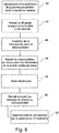
- the Figure 8 schematically illustrates the different phases of the procedure for implanting the probe which has just been described.
- This procedure is similar to that of a conventional probe, except that due to the absence of internal lumen it is not possible to use a guidewire to place the probe and guide it. in the vessels of the cerebral network. It will then be necessary to use a microcatheter instead, according to procedures in themselves known to practitioners.
- the first step (block 40) consists in introducing into the venous system up to the target zone an assembly formed of a microcatheter and a guidewire.
- microprobe is then introduced into the microcatheter (block 44), then the microcatheter is partially withdrawn to gradually uncover the electrodes of the microprobe (block 46).
- the electrical tests are then carried out, automatically or manually (block 48). Once these tests have been carried out, when we are sure that the probe is perfectly functional, the microcatheter is completely withdrawn (block 50), or else locked in place if it is a microcatheter that can be permanently implanted as such. than that described for example in the EP 2 682 151 A1 (Sorin CRM).
- the lead connector can then be connected to the pulse generator (block 50) so that the latter can deliver neurostimulation pulses to the brain.
Claims (11)
- Multipolare Mikrosonde zur Detektions-/Stimulations mit einem Gesamtdurchmesser von weniger als 1,5 French (0,5 mm) zur Implantation in das tiefe zerebrale Venennetz, umfassend eine Vielzahl von mindestens acht einzeln isolierten, miteinander verdrillten Leitungsdrähten (14), wobei jeder Leitungsdraht Folgendes umfasst:- ein elektrisch leitendes Mikrokernkabel (16), das proximal mit einem Pol eines Generators einer aktiven implantierbaren medizinischen Vorrichtung verbunden werden kann; und- eine Isolierschicht (18), die das Kernkabel umgibt und mindestens einen freiliegenden Bereich (38) aufweist, der in der Dicke der Isolierschicht distal ausgebildet ist, um eine Detektions-/Stimulationselektrode der Mikrosonde zu bilden,die Mikrosonde umfasst ferner eine zentrale Trägerstruktur (12) in Form einer Rotationsfläche, wobei die zentrale Trägerstruktur frei ist von i) Leitungsdraht und ii) zentralem Licht,und wobei die Vielzahl von Leiterdrähten (14) als eine Schicht von verdrillten Wicklungen von peripheren Leiterdrähten (14) konfiguriert ist, die von der zentralen Trägerstruktur getragen werden und in Umfangsrichtung darüber verteilt sind.
- Mikrosonde nach Anspruch 1, wobei ein Teil der peripheren Zuleitungen (14) als eine erste Schicht konfiguriert ist, die direkt von der zentralen Trägerstruktur (12) getragen wird, und ein anderer Teil der peripheren Zuleitungen (14') als eine zweite Schicht konfiguriert ist, die von der ersten Schicht getragen wird.
- Mikrosonde nach Anspruch 1, wobei die zentrale Trägerstruktur (12) ein einziges homogenes zylindrisches Element mit massivem oder rohrförmigem Querschnitt umfasst.
- Mikrosonde nach Anspruch 1, wobei die zentrale Trägerstruktur (12) eine Vielzahl homogener zylindrischer Elemente (20) mit massivem oder rohrförmigem Querschnitt umfasst, die miteinander verseilt sind.
- Mikrosonde nach Anspruch 1, wobei die zentrale Trägerstruktur (12) eine Wicklung (26) einer Schutzschaltung gegen induzierte Überströme in einer MRT-Untersuchungssituation umfasst.
- Mikrosonde nach Anspruch 1, wobei der Gesamtdurchmesser der zentralen Trägerstruktur (12) größer ist als der Einheitsdurchmesser eines einzelnen Leitungsdrahtes (14).
- Mikrosonde nach Anspruch 1, wobei die zentrale Trägerstruktur (12) bei Biegebeanspruchung ein höheres elastisches Verformungsvermögen aufweist als alle Einzeldrähte (14).
- Mikrosonde nach Anspruch 1, wobei die zentrale Stützstruktur (12) eine sich verjüngende Struktur mit abnehmendem Durchmesser vom proximalen Bereich (28) zum distalen Bereich (30) ist.
- Mikrosonde nach Anspruch 8, wobei die zentrale Stützstruktur (12) einen sich verjüngenden Übergangsbereich (32) zwischen einem zylindrischen proximalen Bereich (28) mit einem Nenndurchmesser, der größer ist als der Einheitsdurchmesser eines einzelnen Leitungsdrahtes, und einem zylindrischen distalen Bereich (30) mit einem kleineren Durchmesser als der proximale Bereich aufweist.
- Mikrosonde nach Anspruch 1, wobei die Vielzahl der leitenden Drähte (14) 10 bis 50 leitende Drähte pro Schicht umfasst.
- Mikrosonde nach Anspruch 1, wobei der Einheitsdurchmesser eines einzelnen Leitungsdrahtes (14) zwischen 15 und 25 µm liegt.
Applications Claiming Priority (1)
| Application Number | Priority Date | Filing Date | Title |
|---|---|---|---|
| FR1551295 | 2015-02-17 |
Publications (2)
| Publication Number | Publication Date |
|---|---|
| EP3058983A1 EP3058983A1 (de) | 2016-08-24 |
| EP3058983B1 true EP3058983B1 (de) | 2021-10-13 |
Family
ID=52829163
Family Applications (1)
| Application Number | Title | Priority Date | Filing Date |
|---|---|---|---|
| EP16154603.1A Active EP3058983B1 (de) | 2015-02-17 | 2016-02-08 | Mikrosonde zur detektion/stimulation, insbesondere für die mehrpunkt-neuromodulation des zentralen nervensystems |
Country Status (2)
| Country | Link |
|---|---|
| US (2) | US9937340B2 (de) |
| EP (1) | EP3058983B1 (de) |
Families Citing this family (9)
| Publication number | Priority date | Publication date | Assignee | Title |
|---|---|---|---|---|
| US20170189674A1 (en) * | 2016-01-04 | 2017-07-06 | Medtronic, Inc. | Medical electrical lead |
| WO2018157214A1 (en) * | 2017-03-02 | 2018-09-07 | Saluda Medical Pty Limited | Electrode assembly |
| EP3372156A1 (de) * | 2017-03-08 | 2018-09-12 | Koninklijke Philips N.V. | Ekg-kabel zur verbindung mit einem ekg-monitor |
| CN111050839B (zh) * | 2017-08-29 | 2023-10-03 | 美敦力公司 | 植入式医疗电引线构造以及相关联的植入系统 |
| EP3542853B1 (de) | 2018-03-23 | 2021-05-05 | Heraeus Deutschland GmbH & Co. KG | Herstellungsverfahren für eine mikroleitung |
| US11426575B2 (en) | 2018-07-06 | 2022-08-30 | Sorin Crm Sas | Connection method for connecting an isolated micro-conductor |
| JP7407119B2 (ja) * | 2018-09-27 | 2023-12-28 | テルモ株式会社 | 医療デバイス |
| US20210098341A1 (en) * | 2019-09-30 | 2021-04-01 | Paradromics Inc. | Microelectrode array and methods of fabricating same |
| DE102019218477B4 (de) * | 2019-11-28 | 2022-01-05 | Heraeus Deutschland GmbH & Co. KG | Mikro-Lead für direktionale Stimulation |
Family Cites Families (13)
| Publication number | Priority date | Publication date | Assignee | Title |
|---|---|---|---|---|
| US5246014A (en) * | 1991-11-08 | 1993-09-21 | Medtronic, Inc. | Implantable lead system |
| US6216045B1 (en) * | 1999-04-26 | 2001-04-10 | Advanced Neuromodulation Systems, Inc. | Implantable lead and method of manufacture |
| US7555349B2 (en) | 2000-09-26 | 2009-06-30 | Advanced Neuromodulation Systems, Inc. | Lead body and method of lead body construction |
| US7831311B2 (en) | 2004-10-21 | 2010-11-09 | Medtronic, Inc. | Reduced axial stiffness implantable medical lead |
| EP2001473A4 (de) | 2006-03-31 | 2012-12-26 | Advanced Neuromodulation Sys | Nachgiebige elektrostimulationsleitungen und verfahren zu ihrer herstellung |
| US7941227B2 (en) | 2008-09-03 | 2011-05-10 | Boston Scientific Neuromodulation Corporation | Implantable electric stimulation system and methods of making and using |
| US20130018445A1 (en) | 2011-01-14 | 2013-01-17 | Ndi Medical, Llc | Neurostimulation lead |
| US8868207B2 (en) * | 2011-01-26 | 2014-10-21 | Boston Scientific Neuromodulation Corporation | Systems and methods for making and using electrical stimulation systems with improved RF compatibility |
| EP2572751B1 (de) * | 2011-09-21 | 2014-10-29 | Sorin CRM SAS | Sonde zur Stimulation einer ausgedehnten Zone in einem Hohlraum des Herzens, die per OTW-Katheterführung in das Netz der tiefen Herzkranzgefäße implantiert werden kann |
| EP2581107A1 (de) * | 2011-10-14 | 2013-04-17 | Sorin CRM SAS | Detektions-/Stimulations-Mikrosonde zum Implantieren in Venen-, Arterien- oder Lymphsystem-Geflechte |
| EP2682151A1 (de) | 2012-07-06 | 2014-01-08 | Sorin CRM SAS | Einführbarer mikrokatheter für Venös-, Arteriell- und Lymphatisches System |
| EP2719422B1 (de) | 2012-10-12 | 2015-02-18 | Sorin CRM SAS | Implantierbare multipolare Mikrosonde zur Erfassung/Stimulation |
| CN104274902B (zh) * | 2014-10-10 | 2017-09-22 | 清华大学 | 一种mri相容的植入式电极及其制造方法 |
-
2016
- 2016-02-08 EP EP16154603.1A patent/EP3058983B1/de active Active
- 2016-02-16 US US15/044,927 patent/US9937340B2/en active Active
-
2018
- 2018-04-06 US US15/947,755 patent/US10183161B2/en active Active
Also Published As
| Publication number | Publication date |
|---|---|
| US10183161B2 (en) | 2019-01-22 |
| US20180221652A1 (en) | 2018-08-09 |
| US9937340B2 (en) | 2018-04-10 |
| US20160235967A1 (en) | 2016-08-18 |
| EP3058983A1 (de) | 2016-08-24 |
Similar Documents
| Publication | Publication Date | Title |
|---|---|---|
| EP3058983B1 (de) | Mikrosonde zur detektion/stimulation, insbesondere für die mehrpunkt-neuromodulation des zentralen nervensystems | |
| EP2719422B1 (de) | Implantierbare multipolare Mikrosonde zur Erfassung/Stimulation | |
| EP4043065A1 (de) | Mikrosonde zur detektion/stimulation, die in venen-, arterien- oder lymphsystem-netze implantiert werden kann | |
| EP2664354B1 (de) | Medizinische Leitung mit einer Ringelektrode zur Implantation in ein Herz- oder Hirngefäß und ein Verfahren zu deren Herstellung | |
| EP2878332B1 (de) | Detektions-/Stimulationsmikrosonde zur Implantation in ein Gefäß des Venen-, Arterien- oder Lymphsystems | |
| EP1932561B1 (de) | Sonde mit Mehrfachverzweigungen und System zur elektrischen Tiefen-Neurostimulation mit Hilfe einer solchen Sonde | |
| EP2455131B1 (de) | Sonde zur Stimulation einer linken Herzkammer, die in das Netz der Herzkranzgefäße implantiert werden kann | |
| EP2384784B1 (de) | Einheit zur endokavitären Stimulation/Defibrillation des linken Herzventrikels | |
| FR2801509A1 (fr) | Sonde electrique medicale ayant une resistance variable a la flexion | |
| EP2682151A1 (de) | Einführbarer mikrokatheter für Venös-, Arteriell- und Lymphatisches System | |
| US9067058B2 (en) | Nano multipole rings for medical microleads | |
| FR2786701A1 (fr) | Systeme a conducteur electrique medical et a dispositif d'introduction, ensemble conducteur pour un tel systeme et son procede de fabrication | |
| EP2719424B1 (de) | Intraseptale Sonde zur Stimulation des linken Ventrikels | |
| EP2719423B1 (de) | Atraumatische Mikrosonde zur Erfassung/Stimulation | |
| EP2559453B1 (de) | Leiter zur Implantation in die Herzkranzgefäße zur mehrzonigen Stimulation eines linken Herzraums | |
| EP2275170B1 (de) | Implantateinheit zum Einsetzen in das Koronarvenennetz, die eine Stimulationssonde mit Verankerungsschraube umfasst | |
| EP1961444B1 (de) | Nichtlineare Sonde und System zur tiefen Elektroneurostimulation, das eine solche Sonde umfasst | |
| JP2011500209A (ja) | 非コイル状のワイヤ構造物を備えた刺激用および検知用リード線 | |
| EP2732848B1 (de) | Mikroleiter zur implantation in die tiefen herzkranzgefässe mit einem verformbaren proximalen teil | |
| EP2810686B1 (de) | Einheit zum Implantieren in den koronaren Venenkreislauf zur Stimulation einer linken Herzhöhle |
Legal Events
| Date | Code | Title | Description |
|---|---|---|---|
| PUAI | Public reference made under article 153(3) epc to a published international application that has entered the european phase |
Free format text: ORIGINAL CODE: 0009012 |
|
| AK | Designated contracting states |
Kind code of ref document: A1 Designated state(s): AL AT BE BG CH CY CZ DE DK EE ES FI FR GB GR HR HU IE IS IT LI LT LU LV MC MK MT NL NO PL PT RO RS SE SI SK SM TR |
|
| AX | Request for extension of the european patent |
Extension state: BA ME |
|
| STAA | Information on the status of an ep patent application or granted ep patent |
Free format text: STATUS: REQUEST FOR EXAMINATION WAS MADE |
|
| 17P | Request for examination filed |
Effective date: 20170223 |
|
| RBV | Designated contracting states (corrected) |
Designated state(s): AL AT BE BG CH CY CZ DE DK EE ES FI FR GB GR HR HU IE IS IT LI LT LU LV MC MK MT NL NO PL PT RO RS SE SI SK SM TR |
|
| GRAP | Despatch of communication of intention to grant a patent |
Free format text: ORIGINAL CODE: EPIDOSNIGR1 |
|
| STAA | Information on the status of an ep patent application or granted ep patent |
Free format text: STATUS: GRANT OF PATENT IS INTENDED |
|
| INTG | Intention to grant announced |
Effective date: 20210428 |
|
| GRAS | Grant fee paid |
Free format text: ORIGINAL CODE: EPIDOSNIGR3 |
|
| GRAA | (expected) grant |
Free format text: ORIGINAL CODE: 0009210 |
|
| STAA | Information on the status of an ep patent application or granted ep patent |
Free format text: STATUS: THE PATENT HAS BEEN GRANTED |
|
| AK | Designated contracting states |
Kind code of ref document: B1 Designated state(s): AL AT BE BG CH CY CZ DE DK EE ES FI FR GB GR HR HU IE IS IT LI LT LU LV MC MK MT NL NO PL PT RO RS SE SI SK SM TR |
|
| REG | Reference to a national code |
Ref country code: GB Ref legal event code: FG4D Free format text: NOT ENGLISH |
|
| REG | Reference to a national code |
Ref country code: CH Ref legal event code: EP |
|
| REG | Reference to a national code |
Ref country code: DE Ref legal event code: R096 Ref document number: 602016064809 Country of ref document: DE |
|
| REG | Reference to a national code |
Ref country code: IE Ref legal event code: FG4D Free format text: LANGUAGE OF EP DOCUMENT: FRENCH |
|
| REG | Reference to a national code |
Ref country code: AT Ref legal event code: REF Ref document number: 1437720 Country of ref document: AT Kind code of ref document: T Effective date: 20211115 |
|
| REG | Reference to a national code |
Ref country code: LT Ref legal event code: MG9D |
|
| REG | Reference to a national code |
Ref country code: NL Ref legal event code: MP Effective date: 20211013 |
|
| REG | Reference to a national code |
Ref country code: AT Ref legal event code: MK05 Ref document number: 1437720 Country of ref document: AT Kind code of ref document: T Effective date: 20211013 |
|
| PG25 | Lapsed in a contracting state [announced via postgrant information from national office to epo] |
Ref country code: RS Free format text: LAPSE BECAUSE OF FAILURE TO SUBMIT A TRANSLATION OF THE DESCRIPTION OR TO PAY THE FEE WITHIN THE PRESCRIBED TIME-LIMIT Effective date: 20211013 Ref country code: LT Free format text: LAPSE BECAUSE OF FAILURE TO SUBMIT A TRANSLATION OF THE DESCRIPTION OR TO PAY THE FEE WITHIN THE PRESCRIBED TIME-LIMIT Effective date: 20211013 Ref country code: FI Free format text: LAPSE BECAUSE OF FAILURE TO SUBMIT A TRANSLATION OF THE DESCRIPTION OR TO PAY THE FEE WITHIN THE PRESCRIBED TIME-LIMIT Effective date: 20211013 Ref country code: BG Free format text: LAPSE BECAUSE OF FAILURE TO SUBMIT A TRANSLATION OF THE DESCRIPTION OR TO PAY THE FEE WITHIN THE PRESCRIBED TIME-LIMIT Effective date: 20220113 Ref country code: AT Free format text: LAPSE BECAUSE OF FAILURE TO SUBMIT A TRANSLATION OF THE DESCRIPTION OR TO PAY THE FEE WITHIN THE PRESCRIBED TIME-LIMIT Effective date: 20211013 |
|
| REG | Reference to a national code |
Ref country code: DE Ref legal event code: R082 Ref document number: 602016064809 Country of ref document: DE Representative=s name: PAGE, WHITE & FARRER GERMANY LLP, DE |
|
| PG25 | Lapsed in a contracting state [announced via postgrant information from national office to epo] |
Ref country code: IS Free format text: LAPSE BECAUSE OF FAILURE TO SUBMIT A TRANSLATION OF THE DESCRIPTION OR TO PAY THE FEE WITHIN THE PRESCRIBED TIME-LIMIT Effective date: 20220213 Ref country code: SE Free format text: LAPSE BECAUSE OF FAILURE TO SUBMIT A TRANSLATION OF THE DESCRIPTION OR TO PAY THE FEE WITHIN THE PRESCRIBED TIME-LIMIT Effective date: 20211013 Ref country code: PT Free format text: LAPSE BECAUSE OF FAILURE TO SUBMIT A TRANSLATION OF THE DESCRIPTION OR TO PAY THE FEE WITHIN THE PRESCRIBED TIME-LIMIT Effective date: 20220214 Ref country code: PL Free format text: LAPSE BECAUSE OF FAILURE TO SUBMIT A TRANSLATION OF THE DESCRIPTION OR TO PAY THE FEE WITHIN THE PRESCRIBED TIME-LIMIT Effective date: 20211013 Ref country code: NO Free format text: LAPSE BECAUSE OF FAILURE TO SUBMIT A TRANSLATION OF THE DESCRIPTION OR TO PAY THE FEE WITHIN THE PRESCRIBED TIME-LIMIT Effective date: 20220113 Ref country code: NL Free format text: LAPSE BECAUSE OF FAILURE TO SUBMIT A TRANSLATION OF THE DESCRIPTION OR TO PAY THE FEE WITHIN THE PRESCRIBED TIME-LIMIT Effective date: 20211013 Ref country code: LV Free format text: LAPSE BECAUSE OF FAILURE TO SUBMIT A TRANSLATION OF THE DESCRIPTION OR TO PAY THE FEE WITHIN THE PRESCRIBED TIME-LIMIT Effective date: 20211013 Ref country code: HR Free format text: LAPSE BECAUSE OF FAILURE TO SUBMIT A TRANSLATION OF THE DESCRIPTION OR TO PAY THE FEE WITHIN THE PRESCRIBED TIME-LIMIT Effective date: 20211013 Ref country code: GR Free format text: LAPSE BECAUSE OF FAILURE TO SUBMIT A TRANSLATION OF THE DESCRIPTION OR TO PAY THE FEE WITHIN THE PRESCRIBED TIME-LIMIT Effective date: 20220114 Ref country code: ES Free format text: LAPSE BECAUSE OF FAILURE TO SUBMIT A TRANSLATION OF THE DESCRIPTION OR TO PAY THE FEE WITHIN THE PRESCRIBED TIME-LIMIT Effective date: 20211013 |
|
| REG | Reference to a national code |
Ref country code: DE Ref legal event code: R097 Ref document number: 602016064809 Country of ref document: DE |
|
| PG25 | Lapsed in a contracting state [announced via postgrant information from national office to epo] |
Ref country code: SM Free format text: LAPSE BECAUSE OF FAILURE TO SUBMIT A TRANSLATION OF THE DESCRIPTION OR TO PAY THE FEE WITHIN THE PRESCRIBED TIME-LIMIT Effective date: 20211013 Ref country code: SK Free format text: LAPSE BECAUSE OF FAILURE TO SUBMIT A TRANSLATION OF THE DESCRIPTION OR TO PAY THE FEE WITHIN THE PRESCRIBED TIME-LIMIT Effective date: 20211013 Ref country code: RO Free format text: LAPSE BECAUSE OF FAILURE TO SUBMIT A TRANSLATION OF THE DESCRIPTION OR TO PAY THE FEE WITHIN THE PRESCRIBED TIME-LIMIT Effective date: 20211013 Ref country code: EE Free format text: LAPSE BECAUSE OF FAILURE TO SUBMIT A TRANSLATION OF THE DESCRIPTION OR TO PAY THE FEE WITHIN THE PRESCRIBED TIME-LIMIT Effective date: 20211013 Ref country code: DK Free format text: LAPSE BECAUSE OF FAILURE TO SUBMIT A TRANSLATION OF THE DESCRIPTION OR TO PAY THE FEE WITHIN THE PRESCRIBED TIME-LIMIT Effective date: 20211013 Ref country code: CZ Free format text: LAPSE BECAUSE OF FAILURE TO SUBMIT A TRANSLATION OF THE DESCRIPTION OR TO PAY THE FEE WITHIN THE PRESCRIBED TIME-LIMIT Effective date: 20211013 |
|
| PLBE | No opposition filed within time limit |
Free format text: ORIGINAL CODE: 0009261 |
|
| STAA | Information on the status of an ep patent application or granted ep patent |
Free format text: STATUS: NO OPPOSITION FILED WITHIN TIME LIMIT |
|
| 26N | No opposition filed |
Effective date: 20220714 |
|
| PG25 | Lapsed in a contracting state [announced via postgrant information from national office to epo] |
Ref country code: MC Free format text: LAPSE BECAUSE OF FAILURE TO SUBMIT A TRANSLATION OF THE DESCRIPTION OR TO PAY THE FEE WITHIN THE PRESCRIBED TIME-LIMIT Effective date: 20211013 |
|
| REG | Reference to a national code |
Ref country code: CH Ref legal event code: PL |
|
| REG | Reference to a national code |
Ref country code: BE Ref legal event code: MM Effective date: 20220228 |
|
| PG25 | Lapsed in a contracting state [announced via postgrant information from national office to epo] |
Ref country code: LU Free format text: LAPSE BECAUSE OF NON-PAYMENT OF DUE FEES Effective date: 20220208 Ref country code: AL Free format text: LAPSE BECAUSE OF FAILURE TO SUBMIT A TRANSLATION OF THE DESCRIPTION OR TO PAY THE FEE WITHIN THE PRESCRIBED TIME-LIMIT Effective date: 20211013 |
|
| PG25 | Lapsed in a contracting state [announced via postgrant information from national office to epo] |
Ref country code: SI Free format text: LAPSE BECAUSE OF FAILURE TO SUBMIT A TRANSLATION OF THE DESCRIPTION OR TO PAY THE FEE WITHIN THE PRESCRIBED TIME-LIMIT Effective date: 20211013 |
|
| PG25 | Lapsed in a contracting state [announced via postgrant information from national office to epo] |
Ref country code: LI Free format text: LAPSE BECAUSE OF NON-PAYMENT OF DUE FEES Effective date: 20220228 Ref country code: IE Free format text: LAPSE BECAUSE OF NON-PAYMENT OF DUE FEES Effective date: 20220208 Ref country code: CH Free format text: LAPSE BECAUSE OF NON-PAYMENT OF DUE FEES Effective date: 20220228 |
|
| PG25 | Lapsed in a contracting state [announced via postgrant information from national office to epo] |
Ref country code: BE Free format text: LAPSE BECAUSE OF NON-PAYMENT OF DUE FEES Effective date: 20220228 |
|
| PGFP | Annual fee paid to national office [announced via postgrant information from national office to epo] |
Ref country code: FR Payment date: 20230227 Year of fee payment: 8 |
|
| PGFP | Annual fee paid to national office [announced via postgrant information from national office to epo] |
Ref country code: IT Payment date: 20230209 Year of fee payment: 8 |
|
| P01 | Opt-out of the competence of the unified patent court (upc) registered |
Effective date: 20230714 |
|
| PG25 | Lapsed in a contracting state [announced via postgrant information from national office to epo] |
Ref country code: HU Free format text: LAPSE BECAUSE OF FAILURE TO SUBMIT A TRANSLATION OF THE DESCRIPTION OR TO PAY THE FEE WITHIN THE PRESCRIBED TIME-LIMIT; INVALID AB INITIO Effective date: 20160208 |
|
| PG25 | Lapsed in a contracting state [announced via postgrant information from national office to epo] |
Ref country code: MK Free format text: LAPSE BECAUSE OF FAILURE TO SUBMIT A TRANSLATION OF THE DESCRIPTION OR TO PAY THE FEE WITHIN THE PRESCRIBED TIME-LIMIT Effective date: 20211013 Ref country code: CY Free format text: LAPSE BECAUSE OF FAILURE TO SUBMIT A TRANSLATION OF THE DESCRIPTION OR TO PAY THE FEE WITHIN THE PRESCRIBED TIME-LIMIT Effective date: 20211013 |
|
| PGFP | Annual fee paid to national office [announced via postgrant information from national office to epo] |
Ref country code: DE Payment date: 20240213 Year of fee payment: 9 Ref country code: GB Payment date: 20240221 Year of fee payment: 9 |