EP3058983B1 - Detection/stimulation microprobe, in particular for multipoint neuromodulation of the central nervous system - Google Patents
Detection/stimulation microprobe, in particular for multipoint neuromodulation of the central nervous system Download PDFInfo
- Publication number
- EP3058983B1 EP3058983B1 EP16154603.1A EP16154603A EP3058983B1 EP 3058983 B1 EP3058983 B1 EP 3058983B1 EP 16154603 A EP16154603 A EP 16154603A EP 3058983 B1 EP3058983 B1 EP 3058983B1
- Authority
- EP
- European Patent Office
- Prior art keywords
- microprobe
- support structure
- central support
- diameter
- layer
- Prior art date
- Legal status (The legal status is an assumption and is not a legal conclusion. Google has not performed a legal analysis and makes no representation as to the accuracy of the status listed.)
- Active
Links
- 230000000638 stimulation Effects 0.000 title claims description 18
- 238000001514 detection method Methods 0.000 title claims description 6
- 230000004007 neuromodulation Effects 0.000 title description 6
- 210000003169 central nervous system Anatomy 0.000 title description 4
- 239000004020 conductor Substances 0.000 claims description 29
- 230000002093 peripheral effect Effects 0.000 claims description 13
- 238000002513 implantation Methods 0.000 claims description 11
- 230000002490 cerebral effect Effects 0.000 claims description 9
- 238000009413 insulation Methods 0.000 claims description 6
- 238000004804 winding Methods 0.000 claims description 6
- 238000005452 bending Methods 0.000 claims description 5
- 239000007787 solid Substances 0.000 claims description 5
- 230000007704 transition Effects 0.000 claims description 4
- 230000005489 elastic deformation Effects 0.000 claims description 3
- 230000003247 decreasing effect Effects 0.000 claims description 2
- WABPQHHGFIMREM-UHFFFAOYSA-N lead(0) Chemical compound [Pb] WABPQHHGFIMREM-UHFFFAOYSA-N 0.000 claims 5
- 239000000523 sample Substances 0.000 description 19
- 210000004556 brain Anatomy 0.000 description 12
- 238000000034 method Methods 0.000 description 11
- 230000000694 effects Effects 0.000 description 7
- 239000000463 material Substances 0.000 description 7
- KDLHZDBZIXYQEI-UHFFFAOYSA-N Palladium Chemical compound [Pd] KDLHZDBZIXYQEI-UHFFFAOYSA-N 0.000 description 4
- 239000004696 Poly ether ether ketone Substances 0.000 description 4
- 239000004952 Polyamide Substances 0.000 description 4
- 229920002647 polyamide Polymers 0.000 description 4
- 229920000728 polyester Polymers 0.000 description 4
- 229920002530 polyetherether ketone Polymers 0.000 description 4
- 229920002635 polyurethane Polymers 0.000 description 4
- 239000004814 polyurethane Substances 0.000 description 4
- 238000013459 approach Methods 0.000 description 3
- 230000006870 function Effects 0.000 description 3
- 230000007383 nerve stimulation Effects 0.000 description 3
- 201000008450 Intracranial aneurysm Diseases 0.000 description 2
- 208000018737 Parkinson disease Diseases 0.000 description 2
- 229910000566 Platinum-iridium alloy Inorganic materials 0.000 description 2
- 229920002614 Polyether block amide Polymers 0.000 description 2
- 208000027418 Wounds and injury Diseases 0.000 description 2
- 206010015037 epilepsy Diseases 0.000 description 2
- 229920000840 ethylene tetrafluoroethylene copolymer Polymers 0.000 description 2
- 229920002313 fluoropolymer Polymers 0.000 description 2
- 239000004811 fluoropolymer Substances 0.000 description 2
- 238000010348 incorporation Methods 0.000 description 2
- 238000003780 insertion Methods 0.000 description 2
- 230000037431 insertion Effects 0.000 description 2
- 230000007774 longterm Effects 0.000 description 2
- 229910052751 metal Inorganic materials 0.000 description 2
- 239000002184 metal Substances 0.000 description 2
- 210000003205 muscle Anatomy 0.000 description 2
- 230000000926 neurological effect Effects 0.000 description 2
- 229910052763 palladium Inorganic materials 0.000 description 2
- 230000007170 pathology Effects 0.000 description 2
- VPRUMANMDWQMNF-UHFFFAOYSA-N phenylethane boronic acid Chemical compound OB(O)CCC1=CC=CC=C1 VPRUMANMDWQMNF-UHFFFAOYSA-N 0.000 description 2
- HWLDNSXPUQTBOD-UHFFFAOYSA-N platinum-iridium alloy Chemical class [Ir].[Pt] HWLDNSXPUQTBOD-UHFFFAOYSA-N 0.000 description 2
- 229920003229 poly(methyl methacrylate) Polymers 0.000 description 2
- 229920000052 poly(p-xylylene) Polymers 0.000 description 2
- 239000004417 polycarbonate Substances 0.000 description 2
- 229920000515 polycarbonate Polymers 0.000 description 2
- 239000004926 polymethyl methacrylate Substances 0.000 description 2
- 229920001343 polytetrafluoroethylene Polymers 0.000 description 2
- 239000004810 polytetrafluoroethylene Substances 0.000 description 2
- 210000000278 spinal cord Anatomy 0.000 description 2
- 210000004281 subthalamic nucleus Anatomy 0.000 description 2
- GUVRBAGPIYLISA-UHFFFAOYSA-N tantalum atom Chemical compound [Ta] GUVRBAGPIYLISA-UHFFFAOYSA-N 0.000 description 2
- 238000012360 testing method Methods 0.000 description 2
- 210000001186 vagus nerve Anatomy 0.000 description 2
- 230000002792 vascular Effects 0.000 description 2
- BQCIDUSAKPWEOX-UHFFFAOYSA-N 1,1-Difluoroethene Chemical compound FC(F)=C BQCIDUSAKPWEOX-UHFFFAOYSA-N 0.000 description 1
- OKTJSMMVPCPJKN-UHFFFAOYSA-N Carbon Chemical compound [C] OKTJSMMVPCPJKN-UHFFFAOYSA-N 0.000 description 1
- 241001415961 Gaviidae Species 0.000 description 1
- 208000012902 Nervous system disease Diseases 0.000 description 1
- 208000025966 Neurological disease Diseases 0.000 description 1
- 239000002033 PVDF binder Substances 0.000 description 1
- 229920001774 Perfluoroether Polymers 0.000 description 1
- 239000004642 Polyimide Substances 0.000 description 1
- 229910000831 Steel Inorganic materials 0.000 description 1
- 241000897276 Termes Species 0.000 description 1
- 210000000577 adipose tissue Anatomy 0.000 description 1
- 230000005540 biological transmission Effects 0.000 description 1
- 239000002041 carbon nanotube Substances 0.000 description 1
- 229910021393 carbon nanotube Inorganic materials 0.000 description 1
- 229920006026 co-polymeric resin Polymers 0.000 description 1
- 239000011248 coating agent Substances 0.000 description 1
- 238000000576 coating method Methods 0.000 description 1
- 238000005516 engineering process Methods 0.000 description 1
- QHSJIZLJUFMIFP-UHFFFAOYSA-N ethene;1,1,2,2-tetrafluoroethene Chemical group C=C.FC(F)=C(F)F QHSJIZLJUFMIFP-UHFFFAOYSA-N 0.000 description 1
- 230000001747 exhibiting effect Effects 0.000 description 1
- PCHJSUWPFVWCPO-UHFFFAOYSA-N gold Chemical compound [Au] PCHJSUWPFVWCPO-UHFFFAOYSA-N 0.000 description 1
- 229910052737 gold Inorganic materials 0.000 description 1
- 239000010931 gold Substances 0.000 description 1
- HCDGVLDPFQMKDK-UHFFFAOYSA-N hexafluoropropylene Chemical group FC(F)=C(F)C(F)(F)F HCDGVLDPFQMKDK-UHFFFAOYSA-N 0.000 description 1
- 208000014674 injury Diseases 0.000 description 1
- 238000009434 installation Methods 0.000 description 1
- 229910052741 iridium Inorganic materials 0.000 description 1
- 210000005240 left ventricle Anatomy 0.000 description 1
- 210000004165 myocardium Anatomy 0.000 description 1
- 210000005036 nerve Anatomy 0.000 description 1
- HLXZNVUGXRDIFK-UHFFFAOYSA-N nickel titanium Chemical compound [Ti].[Ti].[Ti].[Ti].[Ti].[Ti].[Ti].[Ti].[Ti].[Ti].[Ti].[Ni].[Ni].[Ni].[Ni].[Ni].[Ni].[Ni].[Ni].[Ni].[Ni].[Ni].[Ni].[Ni].[Ni] HLXZNVUGXRDIFK-UHFFFAOYSA-N 0.000 description 1
- 229910001000 nickel titanium Inorganic materials 0.000 description 1
- 210000000578 peripheral nerve Anatomy 0.000 description 1
- 210000001428 peripheral nervous system Anatomy 0.000 description 1
- 229920001721 polyimide Polymers 0.000 description 1
- 229920000642 polymer Polymers 0.000 description 1
- -1 polytetrafluoroethylene Polymers 0.000 description 1
- 125000004805 propylene group Chemical group [H]C([H])([H])C([H])([*:1])C([H])([H])[*:2] 0.000 description 1
- 210000003625 skull Anatomy 0.000 description 1
- 230000003068 static effect Effects 0.000 description 1
- 239000010959 steel Substances 0.000 description 1
- 230000004936 stimulating effect Effects 0.000 description 1
- 239000000126 substance Substances 0.000 description 1
- 238000001356 surgical procedure Methods 0.000 description 1
- 229910052715 tantalum Inorganic materials 0.000 description 1
- BFKJFAAPBSQJPD-UHFFFAOYSA-N tetrafluoroethene Chemical group FC(F)=C(F)F BFKJFAAPBSQJPD-UHFFFAOYSA-N 0.000 description 1
- 230000008733 trauma Effects 0.000 description 1
Images

Classifications
-
- A—HUMAN NECESSITIES
- A61—MEDICAL OR VETERINARY SCIENCE; HYGIENE
- A61N—ELECTROTHERAPY; MAGNETOTHERAPY; RADIATION THERAPY; ULTRASOUND THERAPY
- A61N1/00—Electrotherapy; Circuits therefor
- A61N1/02—Details
- A61N1/04—Electrodes
- A61N1/05—Electrodes for implantation or insertion into the body, e.g. heart electrode
- A61N1/0551—Spinal or peripheral nerve electrodes
-
- A—HUMAN NECESSITIES
- A61—MEDICAL OR VETERINARY SCIENCE; HYGIENE
- A61N—ELECTROTHERAPY; MAGNETOTHERAPY; RADIATION THERAPY; ULTRASOUND THERAPY
- A61N1/00—Electrotherapy; Circuits therefor
- A61N1/02—Details
- A61N1/04—Electrodes
- A61N1/05—Electrodes for implantation or insertion into the body, e.g. heart electrode
- A61N1/0526—Head electrodes
- A61N1/0529—Electrodes for brain stimulation
-
- A—HUMAN NECESSITIES
- A61—MEDICAL OR VETERINARY SCIENCE; HYGIENE
- A61N—ELECTROTHERAPY; MAGNETOTHERAPY; RADIATION THERAPY; ULTRASOUND THERAPY
- A61N1/00—Electrotherapy; Circuits therefor
- A61N1/18—Applying electric currents by contact electrodes
- A61N1/32—Applying electric currents by contact electrodes alternating or intermittent currents
- A61N1/36—Applying electric currents by contact electrodes alternating or intermittent currents for stimulation
- A61N1/3605—Implantable neurostimulators for stimulating central or peripheral nerve system
- A61N1/3606—Implantable neurostimulators for stimulating central or peripheral nerve system adapted for a particular treatment
- A61N1/36064—Epilepsy
-
- A—HUMAN NECESSITIES
- A61—MEDICAL OR VETERINARY SCIENCE; HYGIENE
- A61N—ELECTROTHERAPY; MAGNETOTHERAPY; RADIATION THERAPY; ULTRASOUND THERAPY
- A61N1/00—Electrotherapy; Circuits therefor
- A61N1/18—Applying electric currents by contact electrodes
- A61N1/32—Applying electric currents by contact electrodes alternating or intermittent currents
- A61N1/36—Applying electric currents by contact electrodes alternating or intermittent currents for stimulation
- A61N1/3605—Implantable neurostimulators for stimulating central or peripheral nerve system
- A61N1/3606—Implantable neurostimulators for stimulating central or peripheral nerve system adapted for a particular treatment
- A61N1/36067—Movement disorders, e.g. tremor or Parkinson disease
-
- A—HUMAN NECESSITIES
- A61—MEDICAL OR VETERINARY SCIENCE; HYGIENE
- A61N—ELECTROTHERAPY; MAGNETOTHERAPY; RADIATION THERAPY; ULTRASOUND THERAPY
- A61N1/00—Electrotherapy; Circuits therefor
- A61N1/18—Applying electric currents by contact electrodes
- A61N1/32—Applying electric currents by contact electrodes alternating or intermittent currents
- A61N1/36—Applying electric currents by contact electrodes alternating or intermittent currents for stimulation
- A61N1/3605—Implantable neurostimulators for stimulating central or peripheral nerve system
- A61N1/3606—Implantable neurostimulators for stimulating central or peripheral nerve system adapted for a particular treatment
- A61N1/36071—Pain
-
- A—HUMAN NECESSITIES
- A61—MEDICAL OR VETERINARY SCIENCE; HYGIENE
- A61N—ELECTROTHERAPY; MAGNETOTHERAPY; RADIATION THERAPY; ULTRASOUND THERAPY
- A61N1/00—Electrotherapy; Circuits therefor
- A61N1/02—Details
- A61N1/08—Arrangements or circuits for monitoring, protecting, controlling or indicating
- A61N1/086—Magnetic resonance imaging [MRI] compatible leads
Definitions
- the invention relates to “active implantable medical devices” as defined by Directive 90/385 / EEC of June 20, 1990 of the Council of the European Communities.
- It relates more precisely to a neuromodulation microprobe operating by multipoint stimulation of the central nervous system.
- Such a probe is typically intended to be implanted in the cerebral venous network so as to reach specific target areas of the brain in order to apply electrical neurostimulation impulses thereto to treat certain pathologies such as Parkinson's disease, epilepsy, etc. ., techniques grouped under the general name DBS ( Deep Brain Stimulation ). It may also involve stimulating the spinal cord, in particular for the treatment of pain, these techniques being known under the general name SCS ( Spinal Cord Stimulation ).
- DBS Deep Brain Stimulation
- SCS Spinal Cord Stimulation
- VNS Vagus Nerve Stimulation, vagus nerve stimulation
- the specificity of the probes for the stimulation of the central nervous system results mainly in the diameter of these probes, imperatively less than 1.5 French, or 0.5 mm (hence the term "microprobe"), as well as in the number electrodes needed to allow "multipoint" stimulation.
- the aim of the present invention is to provide a microprobe structure which makes it possible to reach deep areas of the brain such as regions, potentially known to be effective for treatment by neuromodulation, known as the subthalamic nucleus (STN) or globus. internal pallidus (GPI), and to stimulate very precisely target areas located in these regions.
- STN subthalamic nucleus
- GPI internal pallidus
- probes of too large a diameter can cause significant neurological damage during implantation surgery. It is therefore necessary to greatly reduce the diameter of the microprobe, but while still retaining excellent seaworthiness properties within the venous network to allow its placement.
- the cerebral arterial venous network indeed comprises strong tortuosities and numerous branches, and it is essential to avoid traumas that could generate a too rigid probe.
- a too flexible microprobe would be difficult to set up, because of too little torsional stiffness to allow the transmission over the entire length of the probe body, to the distal end, of a movement. rotation imprinted from the proximal end (lack of "torquability").
- a too flexible microprobe could not progress in the biological network without bracing under the effect of an axial thrust (lack of "pushability").
- the implantable probe be compatible with 1.6 French (0.53 mm) catheters such as those already used today in interventional neuroradiology, for example for the release of devices such as springs ( coils ) during the treatment of intracranial aneurysms. This imperatively implies for the probe an overall diameter of less than 1.5 French (0.5 mm).
- the electrodes of a neurostimulation microprobe must have an extremely small surface area, so as to be able to precisely stimulate the target areas without risking producing any effects. severe psychiatric secondary education, which unfortunately occurs today in a significant percentage of interventions.
- the US 2006/0089697 A1 describes a probe comprising a plurality of independent wound conductors, distributed around a hollow tube, the assembly being protected by an external insulating sleeve.
- the tube is crossed right through by a central lumen intended to allow the insertion of a delivery mandrel inserted into this lumen during implantation.
- the overall diameter of this structure (at least 0.8 mm) is, however, much too large to reach the deepest target areas of the brain.
- the US 2013/0018445 A1 describes a neurostimulation probe capable of comprising up to 49 conductive strands wound in a spiral and individually insulated, but in an application of stimulation of a peripheral nerve located in muscle or adipose tissue, therefore in an environment where the constraints do not arise very small diameter and seaworthy.
- the EP 2 581 107 A1 and EP 2 719 422 A1 (Sorin CRM) describe structures of microprobes implantable in venous and arterial networks or lymphatics. These microprobes are however essentially designed for implantation in the coronary venous network for the stimulation of the left ventricle of the myocardium, therefore in cardiological applications. Their structure is in fact specifically designed to withstand the very severe fatigue stresses associated with heart beats, which fatigue the material under the effect of repeated flexures over hundreds of millions of cycles, which can cause it to break and limit its duration. life.
- the invention provides a microprobe of the general type disclosed for example by EP 2 719 422 A1 supra, i.e. a multipolar microprobe with an overall diameter of less than 1.5 French (0.5mm) comprising a plurality of at least eight individually insulated conductive wires twisted together, each conductor wire comprising: an electrically conductive core microcable, able to be partially connected proximal to a pole of a generator of an active implantable medical device; and an insulating layer surrounding the core cable, and having at least one stripped area formed in the thickness of the partially distal insulating layer to form a detection / stimulation electrode of the microprobe.
- a microprobe of the general type disclosed for example by EP 2 719 422 A1 supra, i.e. a multipolar microprobe with an overall diameter of less than 1.5 French (0.5mm) comprising a plurality of at least eight individually insulated conductive wires twisted together, each conductor wire comprising: an electrically conductive core microcable, able to be partially
- the microprobe further comprises a central support structure in the form of a surface of revolution, this central support structure being devoid of i) conductive wire and ii) central light, and the conductive wires of said plurality are configured as a layer of a twisted winding of peripheral conductive wires carried by the central support structure and circumferentially distributed thereon.
- FIG. 1 there is generally illustrated a microprobe 10 according to the invention, implanted in the cerebral vascular network in order to be able to selectively stimulate deep areas of the brain by localized application of electrical impulses.
- the electrodes of this microprobe can also function, where appropriate, as detection electrodes to collect locally produced electrical potentials.
- Stimulation of target areas of the brain makes it possible in particular to implement neuromodulation techniques intended to treat pathologies such as Parkinson's disease, epilepsy and other neurological diseases.
- the stimulation microprobes that can be envisaged for this purpose must not only be very robust, in order to guarantee long-term biostability (these microprobes are intended to be permanently implanted), but also a very small size, with an overall diameter. less than 1.5 French (0.5 mm). In particular, 1.5 French microprobes would be advantageously compatible with 1.6 French (0.53 mm) catheters, already used today in interventional neuroradiology, for example for the release of devices such as springs (coils) when treating intracranial aneurysms.
- these microprobes must have a large number of electrodes, typically 20 to 100 electrodes, independently selectable so as to be able to choose the stimulation zones very precisely as a function of the desired effect. It is also desirable to be able to choose the axial direction in which these electrodes act, in order to optimize the effect produced and to avoid the appearance of undesirable side effects.
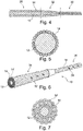
- FIGS. 2a and 2b show, respectively in cross section and in side view, the microprobe structure proposed by the present invention.
- the microprobe 10 comprises a central support structure 12 in the form of a surface of revolution, covered at its periphery with a plurality of peripheral conductive wires 14 carried by this central support structure 12 and circumferentially distributed thereon.
- Each of the peripheral conductor wires 14 includes an electrically conductive core microcable 16 and an insulation layer 18 surrounding the core cable.
- the core microcable can be made of a conductive metal such as platinum-iridium alloy, MP35N steel, nitinol, etc.
- a conductive metal such as platinum-iridium alloy, MP35N steel, nitinol, etc.
- Various core cable structures suitable for this application are described in particular in EP 2 581 107 A1 cited above (Sorin CRM), to which reference may be made for more details.
- the core microcable 16 materials such as carbon nanotubes, which are materials of choice for their exceptional mechanical strength characteristics and their very good electrical conductivity properties.
- materials such as polyurethanes (PU), polyesters (PET), polyamides (PA), polycarbonates (PC), polyimides, fluoropolymers, polyether-ether-ketone (PEEK) can be used.
- PU polyurethanes
- PET polyesters
- PA polyamides
- PC polycarbonates
- PEEK polyimides
- fluoropolymers polyether-ether-ketone
- PEEK polyether-ether-ketone
- PMM polymethyl methacrylate
- fluoropolymers which also have very good insulation quality, in particular PTFE (polytetrafluoroethylene), FEP (perfluorinated propylene), PFA (perfluoroalkoxy copolymer resin), THV (tetrafluoroethylene, hexafluoropropylene, vinylidene fluoride), PVDF (polyvinylidene fluoride), EFEP (ethylene propylene fluorinated ethylene), or ETFE (ethylene tetrafluoroethylene).
- PTFE polytetrafluoroethylene
- FEP perfluorinated propylene
- PFA perfluoroalkoxy copolymer resin
- THV tetrafluoroethylene, hexafluoropropylene, vinylidene fluoride
- PVDF polyvinylidene fluoride
- EFEP ethylene propylene fluorinated ethylene
- ETFE ethylene tetrafluoroethylene
- Each of the conductive wires has in the distal region of the probe at least one bare zone (as illustrated at 38 or 38 'on the Figure 6 ) formed in the thickness of the insulation layer to form a detection / stimulation electrode of the microprobe.
- the architecture of the microprobe according to the invention makes it possible to reduce the size of the probe in very large proportions while guaranteeing a large number of lines. isolated electrics, connected to independent electrodes and therefore programmable according to multiple configurations by the generator to which the microprobes are connected.
- this structure does not include a central lumen (that is to say a channel opening at both ends of the probe), so that for the installation of the microprobe the guidance will be done by the 'outside via a delivery catheter, not through a guidewire inserted into a central lumen.
- a central lumen that is to say a channel opening at both ends of the probe
- a cylindrical proximal part 28 of nominal diameter connected to a distal portion 30 of smaller diameter via a tapered transition portion 32.
- the proximal portion 28 of larger diameter provides "pushability", i.e. the ability to advance the microprobe under the effect of an axial stress applied for example by means of an operating handle from the proximal end, while the much thinner distal part 30 makes it easy to reach deep, narrow vessels in the cerebral region .
- FIG. 5 illustrates an exemplary embodiment of a microprobe according to the invention with twenty-six electrodes, therefore comprising twenty-six peripheral conductor wires 14 carried by a central support structure 12.
- the very great compactness of the structure makes it possible to use insulated wires which can have a diameter as small as 15 to 25 ⁇ m, so that it is possible to place typically up to fifty conductive wires, and therefore to have as many of independent electrodes, in an overall diameter of 0.40 mm for a unit conductor wire diameter of 25 ⁇ m (the number of conductor wires increasing geometrically by reducing the size of these conductors).
- the Figures 6 and 7 illustrate a variant comprising two superimposed layers of conductors on the central support structure, with a first layer of peripheral conductor wires 14 directly carried by the central support structure 12, and a second layer of peripheral conductor wires 14 'carried by the first layer of conductors 14. It is possible to independently exploit all the layers of the structure and thus multiply the possibilities, with up to more than one hundred conductors 14 or 14 'which can be used independently in the same structure, the overall diameter of which does not exceed 0.5. mm.
- the two layers of respective conductors 14 and 14 ' can be offset axially, with a proximal zone 34 where it is the second layer of the conductors 14' which is visible, and a distal zone 36 where it is the surface of the conductors 14. of the first visible layer.
- the proximal zone 34 will be that carrying the electrodes 38 'connected to the conductors 14', while the distal zone 36 will be that carrying the electrodes 38 connected to the conductors 14.
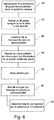
- the Figure 8 schematically illustrates the different phases of the procedure for implanting the probe which has just been described.
- This procedure is similar to that of a conventional probe, except that due to the absence of internal lumen it is not possible to use a guidewire to place the probe and guide it. in the vessels of the cerebral network. It will then be necessary to use a microcatheter instead, according to procedures in themselves known to practitioners.
- the first step (block 40) consists in introducing into the venous system up to the target zone an assembly formed of a microcatheter and a guidewire.
- microprobe is then introduced into the microcatheter (block 44), then the microcatheter is partially withdrawn to gradually uncover the electrodes of the microprobe (block 46).
- the electrical tests are then carried out, automatically or manually (block 48). Once these tests have been carried out, when we are sure that the probe is perfectly functional, the microcatheter is completely withdrawn (block 50), or else locked in place if it is a microcatheter that can be permanently implanted as such. than that described for example in the EP 2 682 151 A1 (Sorin CRM).
- the lead connector can then be connected to the pulse generator (block 50) so that the latter can deliver neurostimulation pulses to the brain.
Landscapes
- Health & Medical Sciences (AREA)
- Neurosurgery (AREA)
- Neurology (AREA)
- Public Health (AREA)
- Biomedical Technology (AREA)
- Nuclear Medicine, Radiotherapy & Molecular Imaging (AREA)
- Radiology & Medical Imaging (AREA)
- Life Sciences & Earth Sciences (AREA)
- Animal Behavior & Ethology (AREA)
- General Health & Medical Sciences (AREA)
- Engineering & Computer Science (AREA)
- Veterinary Medicine (AREA)
- Heart & Thoracic Surgery (AREA)
- Cardiology (AREA)
- Orthopedic Medicine & Surgery (AREA)
- Hospice & Palliative Care (AREA)
- Pain & Pain Management (AREA)
- Psychology (AREA)
- Electrotherapy Devices (AREA)
- Measurement And Recording Of Electrical Phenomena And Electrical Characteristics Of The Living Body (AREA)
Description
L'invention concerne les "dispositifs médicaux implantables actifs" tels que définis par la directive 90/385/CEE du 20 juin 1990 du Conseil des communautés européennes.The invention relates to “active implantable medical devices” as defined by Directive 90/385 / EEC of June 20, 1990 of the Council of the European Communities.
Elle concerne plus précisément une microsonde de neuromodulation opérant par stimulation multipoint du système nerveux central.It relates more precisely to a neuromodulation microprobe operating by multipoint stimulation of the central nervous system.
Une telle sonde est typiquement destinée à être implantée dans le réseau veineux cérébral de manière à atteindre des zones cibles spécifiques du cerveau afin d'y appliquer des impulsions électriques de neurostimulation pour traiter certaines pathologies telles que la maladie de Parkinson, l'épilepsie, etc., techniques regroupées sous la dénomination générale DBS (Deep Brain Stimulation, stimulation profonde du cerveau). Il peut également s'agir de stimuler la moelle épinière, notamment pour le traitement de la douleur, ces techniques étant connues sous la dénomination générale SCS (Spinal Cord Stimulation, stimulation de la moelle épinière).Such a probe is typically intended to be implanted in the cerebral venous network so as to reach specific target areas of the brain in order to apply electrical neurostimulation impulses thereto to treat certain pathologies such as Parkinson's disease, epilepsy, etc. ., techniques grouped under the general name DBS ( Deep Brain Stimulation ). It may also involve stimulating the spinal cord, in particular for the treatment of pain, these techniques being known under the general name SCS ( Spinal Cord Stimulation ).
Ces techniques se distinguent par de nombreux aspects, notamment par les moyens utilisés, de celles qui sont employées en cardiologie ou pour d'autres types de stimulation nerveuse où c'est le système nerveux périphérique qui est stimulé, comme dans les techniques dites VNS (Vagus Nerve Stimulation, stimulation du nerf vague) ou analogues, où les électrodes sont placées au niveau des nerfs ou des muscles, donc dans des zones beaucoup plus aisément accessibles.These techniques are distinguished by many aspects, in particular by the means used, from those which are used in cardiology or for other types of nerve stimulation where it is the peripheral nervous system which is stimulated, as in the techniques known as VNS ( Vagus Nerve Stimulation, vagus nerve stimulation) or the like, where the electrodes are placed at the level of the nerves or muscles, therefore in areas that are much more easily accessible.
La spécificité des sondes pour la stimulation du système nerveux central résulte principalement dans le diamètre de ces sondes, impérativement inférieur à 1,5 French, soit 0,5 mm (d'où le terme de "microsonde"), ainsi que dans le nombre d'électrodes nécessaires pour permettre une stimulation "multipoint".The specificity of the probes for the stimulation of the central nervous system results mainly in the diameter of these probes, imperatively less than 1.5 French, or 0.5 mm (hence the term "microprobe"), as well as in the number electrodes needed to allow "multipoint" stimulation.
Le but de la présente invention est de proposer une structure de microsonde qui permette d'atteindre des zones profondes du cerveau telles que les régions, potentiellement connues comme efficaces pour un traitement par neuromodulation, connues sous le nom de noyau subthalamique (STN) ou globus pallidus interne (GPI), et de stimuler très précisément des zones cibles situées dans ces régions.The aim of the present invention is to provide a microprobe structure which makes it possible to reach deep areas of the brain such as regions, potentially known to be effective for treatment by neuromodulation, known as the subthalamic nucleus (STN) or globus. internal pallidus (GPI), and to stimulate very precisely target areas located in these regions.
Les solutions actuelles de neurostimulation profonde utilisent en général une approche fortement invasive, basée sur la perforation du crâne et la mise en place de la sonde par un guidage externe.Current deep neurostimulation solutions generally use a highly invasive approach, based on perforation of the skull and placement of the lead by external guidance.
Il serait toutefois souhaitable de pouvoir disposer de moyens permettant une approche beaucoup moins invasive, par un abord veineux mettant en œuvre des techniques comparables à celles utilisées pour la microcathétérisation du cerveau, utilisées dans le cadre de la neuroradiologie interventionnelle. À condition de pouvoir disposer d'une structure de diamètre suffisamment faible et capable de naviguer au sein du réseau veineux et artériel du cerveau, ces techniques pourraient être utilisées pour la pose d'une microsonde. La microsonde doit toutefois rester adaptée à une implantation permanente dans le cerveau.It would however be desirable to be able to have means allowing a much less invasive approach, by a venous approach using techniques comparable to those used for microcatheterization of the brain, used in the context of interventional neuroradiology. On condition of having a structure of sufficiently small diameter and capable of navigating within the venous and arterial network of the brain, these techniques could be used for the insertion of a microprobe. The microprobe must however remain suitable for permanent implantation in the brain.
L'utilisation dans ce contexte de microsondes connues se heurte toutefois à plusieurs difficultés majeures.The use in this context of known microprobes, however, comes up against several major difficulties.
En premier lieu, des sondes de diamètre trop élevé peuvent causer des dégâts neurologiques importants lors de l'intervention chirurgicale d'implantation. Il est donc nécessaire de réduire très fortement le diamètre de la microsonde, mais en lui conservant toutefois d'excellentes propriétés de navigabilité au sein du réseau veineux pour permettre sa mise en place. Le réseau veineux artériel cérébral comprend en effet de fortes tortuosités et de nombreux embranchements, et il est indispensable d'éviter des traumatismes que pourrait engendrer une sonde trop rigide. Mais, inversement, une microsonde trop souple serait difficile à mettre en place, du fait d'une trop faible raideur en torsion pour permettre la transmission sur toute la longueur du corps de sonde, jusqu'à l'extrémité distale, d'un mouvement de rotation imprimé depuis l'extrémité proximale (manque de "torquabilité"). De plus, une microsonde trop souple ne pourrait pas progresser dans le réseau biologique sans arc-boutement sous l'effet d'une poussée axiale (manque de "pushabilité").First, probes of too large a diameter can cause significant neurological damage during implantation surgery. It is therefore necessary to greatly reduce the diameter of the microprobe, but while still retaining excellent seaworthiness properties within the venous network to allow its placement. The cerebral arterial venous network indeed comprises strong tortuosities and numerous branches, and it is essential to avoid traumas that could generate a too rigid probe. But, conversely, a too flexible microprobe would be difficult to set up, because of too little torsional stiffness to allow the transmission over the entire length of the probe body, to the distal end, of a movement. rotation imprinted from the proximal end (lack of "torquability"). In addition, a too flexible microprobe could not progress in the biological network without bracing under the effect of an axial thrust (lack of "pushability").
En deuxième lieu, il est souhaitable que la sonde implantable soit compatible avec les cathéters de 1,6 French (0,53 mm) tels que ceux déjà utilisés aujourd'hui en neuroradiologie interventionnelle par exemple pour la libération de dispositifs tels que des ressorts (coils) lors du traitement des anévrysmes intracrâniens. Ceci implique impérativement pour la sonde un diamètre hors-tout inférieur à 1,5 French (0,5 mm).Secondly, it is desirable that the implantable probe be compatible with 1.6 French (0.53 mm) catheters such as those already used today in interventional neuroradiology, for example for the release of devices such as springs ( coils ) during the treatment of intracranial aneurysms. This imperatively implies for the probe an overall diameter of less than 1.5 French (0.5 mm).
En troisième lieu, les électrodes d'une microsonde de neurostimulation doivent présenter une surface extrêmement réduite, de manière à pouvoir stimuler précisément les zones cibles sans risquer de produire des effets secondaires psychiatriques graves, ce qui survient malheureusement aujourd'hui dans un pourcentage important des interventions.Third, the electrodes of a neurostimulation microprobe must have an extremely small surface area, so as to be able to precisely stimulate the target areas without risking producing any effects. severe psychiatric secondary education, which unfortunately occurs today in a significant percentage of interventions.
Enfin, en quatrième lieu, il est nécessaire de disposer sur une même microsonde d'un nombre très élevé d'électrodes de neurostimulation, toutes sélectionnables indépendamment, de manière à affiner au maximum la précision des points de contact stimulés, l'idéal étant de disposer d'au moins 8, de préférence de 20 à 100 électrodes programmables indépendamment, au surplus avec possibilité de sélectionner des électrodes situées dans des directions angulaires différentes sur une même position longitudinale de la sonde. Cette multiplication du nombre d'électrodes, et par voie de conséquence de conducteurs indépendants, ne doit bien entendu pas se faire au détriment du faible diamètre de la microsonde, indispensable pour réduire la traumaticité de celle-ci et offrir des possibilités d'abord vers des zones profondes du cerveau.Finally, in the fourth place, it is necessary to have on the same microprobe a very high number of neurostimulation electrodes, all independently selectable, so as to refine the precision of the stimulated contact points as much as possible, the ideal being to have at least 8, preferably 20 to 100 independently programmable electrodes, in addition with the possibility of selecting electrodes located in different angular directions on the same longitudinal position of the probe. This multiplication of the number of electrodes, and consequently of independent conductors, must of course not be done to the detriment of the small diameter of the microprobe, essential to reduce the traumaticity of this one and to offer possibilities initially towards deep areas of the brain.
Diverses structures de sondes de neuromodulation à conducteurs multiples ont été proposées, par exemple dans les
Le
Le
Les
Ces aspects sont beaucoup moins critiques dans le cas d'une microsonde de neuromodulation DBS ou SCS, qui est implantée dans un milieu bien plus statique que le cœur et beaucoup moins sujet aux contraintes de fatigue. Bien plus, l'exigence majeure de multiplication du nombre d'électrodes indépendantes (typiquement au moins 8, de préférence 20 à 100 électrodes) ne peut pas être satisfaite par les structures de microsondes décrites dans ces documents, qui ne peuvent intégrer tout au plus que sept conducteurs indépendants dans le diamètre prescrit de 1,5 French (0,5 mm).These aspects are much less critical in the case of a DBS or SCS neuromodulation microprobe, which is implanted in a much more static environment than the heart and much less subject to fatigue constraints. Moreover, the major requirement of multiplying the number of independent electrodes (typically at least 8, preferably 20 to 100 electrodes) cannot be satisfied by the structures of microprobes described in these documents, which cannot integrate at most as seven independent conductors in the prescribed diameter of 1.5 French (0.5 mm).
Ainsi, la présente invention a pour objet de résoudre le problème consistant à disposer d'une microsonde spécifiquement adaptée à la stimulation multipoint du système nerveux central, qui offre :
- la possibilité de multiplier le nombre de conducteurs dans une structure torsadée à la fois compacte et résistante à des sollicitations mécaniques en flexion et souple, en ayant jusqu'à 100 fils isolés dans une dimension inférieure à 0,5 mm ;
- la possibilité de réaliser, dans cette structure, des électrodes de très petite taille, et orientées dans plusieurs directions axiales ; et
- qui soit adaptée à une implantation sur le long terme dans les applications de stimulation neurologique permanente, après mise en place dans le réseau veineux cérébral.
- the possibility of increasing the number of conductors in a twisted structure which is both compact and resistant to mechanical bending and flexible stresses, by having up to 100 insulated wires in a dimension less than 0.5 mm;
- the possibility of producing, in this structure, electrodes of very small size, and oriented in several axial directions; and
- which is suitable for long-term implantation in permanent neurological stimulation applications, after placement in the cerebral venous network.
À cet effet, l'invention propose une microsonde du type général divulgué par exemple par le
De façon caractéristique de l'invention, la microsonde comprend en outre une structure support centrale en forme de surface de révolution, cette structure support centrale étant dépourvue i) de fil conducteur et ii) de lumière centrale, et les fils conducteurs de ladite pluralité sont configurés en une couche d'un enroulement torsadé de fils conducteurs périphériques portés par la structure support centrale et circonférentiellement répartis sur celle-ci.Characteristically of the invention, the microprobe further comprises a central support structure in the form of a surface of revolution, this central support structure being devoid of i) conductive wire and ii) central light, and the conductive wires of said plurality are configured as a layer of a twisted winding of peripheral conductive wires carried by the central support structure and circumferentially distributed thereon.
Selon diverses caractéristiques subsidiaires avantageuses :
- une partie des fils conducteurs périphériques sont configurés en une première couche directement portée par la structure support centrale et une autre partie des fils conducteurs périphériques sont configurés en une deuxième couche portée par ladite première couche ;
- la structure support centrale comprend un élément cylindrique homogène unique de section pleine ou tubulaire, ou bien une pluralité d'éléments cylindriques homogènes de section pleine ou tubulaire toronnés ensemble ;
- la structure support centrale comprend un bobinage d'un circuit de protection contre les surintensités induites en situation d'examen IRM ;
- le diamètre hors-tout de la structure support centrale est supérieur au diamètre unitaire d'un fil conducteur individuel ;
- à l'encontre des sollicitations en flexion, la structure support centrale présente une aptitude à la déformation élastique supérieure à celle de l'ensemble des fils conducteurs individuels ;
- la structure support centrale est une structure effilée avec un diamètre décroissant de la région proximale vers la région distale, notamment une structure comprenant une partie conique de transition entre une partie proximale cylindrique de diamètre nominal supérieur au diamètre unitaire d'un fil conducteur individuel, et une partie distale cylindrique de diamètre inférieur à celui de la partie proximale ;
- la pluralité de fils conducteurs comprend de 10 à 50 fils conducteurs par couche ;
- le diamètre unitaire d'un fil conducteur individuel est compris entre 15 et 25 µm.
- part of the peripheral conductive wires are configured in a first layer directly carried by the central support structure and another part of the peripheral conductive wires are configured in a second layer carried by said first layer;
- the central support structure comprises a single homogeneous cylindrical element of solid or tubular section, or a plurality of homogeneous cylindrical elements of solid or tubular section stranded together;
- the central support structure comprises a winding of a protection circuit against induced overcurrents in an MRI examination situation;
- the overall diameter of the central support structure is greater than the unit diameter of an individual conductor wire;
- against bending stresses, the central support structure has a capacity for elastic deformation greater than that of all the individual conductor wires;
- the central support structure is a tapered structure with a diameter decreasing from the proximal region to the distal region, in particular a structure comprising a tapered transition part between a cylindrical proximal part of nominal diameter greater than the unit diameter of an individual conductive wire, and a cylindrical distal part of diameter smaller than that of the proximal part;
- the plurality of conductive wires comprises 10 to 50 conductive wires per layer;
- the unit diameter of an individual conductor wire is between 15 and 25 µm.
On va maintenant décrire un exemple de mise en œuvre de la présente invention, en référence aux dessins annexés où les mêmes références désignent d'une figure à l'autre des éléments identiques ou fonctionnellement semblables.
- La
Figure 1 illustre de façon générale un exemple d'implantation d'une microsonde selon l'invention dans le réseau vasculaire cérébral. - Les
Figures 2a et 2b montrent, respectivement en section droite et en vue latérale, la structure d'ensemble de la microsonde selon l'invention. - Les
Figures 3a à 3d illustrent diverses variantes de la structure support centrale de la microsonde selon l'invention. - La
Figure 4 illustre une mise en œuvre particulière, avec une structure support centrale comportant une portion conique. - La
Figure 5 illustre, en section droite, un exemple de réalisation d'une microsonde selon l'invention à vingt-six électrodes. - Les
Figures 6 et 7 illustrent, respectivement en vue de côté et en section droite, un mode de réalisation de la microsonde selon l'invention comportant deux couches de conducteurs périphériques superposées. - La
Figure 8 est un organigramme décrivant les différentes phases de la procédure d'implantation d'une microsonde selon l'invention.
- The
Figure 1 generally illustrates an example of implantation of a microprobe according to the invention in the cerebral vascular network. - The
Figures 2a and 2b show, respectively in cross section and in side view, the overall structure of the microprobe according to the invention. - The
Figures 3a to 3d illustrate various variants of the central support structure of the microprobe according to the invention. - The
Figure 4 illustrates a particular implementation, with a central support structure comprising a conical portion. - The
Figure 5 illustrates, in cross section, an exemplary embodiment of a microprobe according to the invention with twenty-six electrodes. - The
Figures 6 and 7 illustrate, respectively in side view and in cross section, an embodiment of the microprobe according to the invention comprising two layers of superimposed peripheral conductors. - The
Figure 8 is a flowchart describing the different phases of the procedure for implanting a microprobe according to the invention.
On va maintenant décrire un exemple de réalisation de l'invention.An embodiment of the invention will now be described.
Sur la
La stimulation de zones cibles du cerveau permet en particulier de mettre en œuvre des techniques de neuromodulation destinées à traiter des pathologies telles que la maladie de Parkinson, l'épilepsie et autres maladies neurologiques.Stimulation of target areas of the brain makes it possible in particular to implement neuromodulation techniques intended to treat pathologies such as Parkinson's disease, epilepsy and other neurological diseases.
Il est de ce fait nécessaire d'accéder à des régions profondes du cerveau, difficilement atteignables aujourd'hui avec les technologies connues.It is therefore necessary to access deep regions of the brain, which are difficult to reach today with known technologies.
Les microsondes de stimulation envisageables à cet effet doivent présenter non seulement une grande robustesse, afin de garantir la biostabilité à long terme (ces microsondes sont destinées à être implantées de façon permanente), mais également une taille très réduite, avec un diamètre hors-tout inférieur à 1,5 French (0,5 mm). En particulier, des microsondes de 1,5 French seraient avantageusement compatibles avec des cathéters de 1,6 French (0,53 mm), déjà utilisés aujourd'hui en neuroradiologie interventionnelle par exemple pour la libération de dispositifs tels que des ressorts (coils) lors du traitement des anévrysmes intracrâniens.The stimulation microprobes that can be envisaged for this purpose must not only be very robust, in order to guarantee long-term biostability (these microprobes are intended to be permanently implanted), but also a very small size, with an overall diameter. less than 1.5 French (0.5 mm). In particular, 1.5 French microprobes would be advantageously compatible with 1.6 French (0.53 mm) catheters, already used today in interventional neuroradiology, for example for the release of devices such as springs (coils) when treating intracranial aneurysms.
Par ailleurs, ces microsondes doivent posséder un nombre élevé d'électrodes, typiquement 20 à 100 électrodes, sélectionnables indépendamment de manière à pouvoir choisir très précisément les zones de stimulation en fonction de l'effet recherché. Il est également souhaitable de pouvoir choisir la direction axiale dans laquelle agissent ces électrodes, afin d'optimiser l'effet produit et éviter l'apparition d'effets secondaires indésirables.Moreover, these microprobes must have a large number of electrodes, typically 20 to 100 electrodes, independently selectable so as to be able to choose the stimulation zones very precisely as a function of the desired effect. It is also desirable to be able to choose the axial direction in which these electrodes act, in order to optimize the effect produced and to avoid the appearance of undesirable side effects.
Les
La microsonde 10 comprend une structure support centrale 12 en forme de surface de révolution, couverte à sa périphérie d'une pluralité de fils conducteurs périphériques 14 portés par cette structure support centrale 12 et circonférentiellement répartis sur celle-ci.The
Chacun des fils conducteurs périphériques 14 comprend un microcâble de cœur 16 électriquement conducteur et une couche d'isolement 18 entourant le câble de cœur.Each of the
Le microcâble de cœur peut être réalisé en un métal conducteur tel qu'un alliage platine-iridium, un acier MP35N, du nitinol, etc. Diverses structures de câble de cœur appropriées à cette application sont décrites en particulier dans le
Pour la couche d'isolement 18, on pourra utiliser des matériaux tels que les polyuréthannes (PU), polyesters (PET), polyamides (PA), polycarbonates (PC), polyimides, polymères fluorés, le polyéther-éther-cétone (PEEK), le poly-p-xylylène (parylène), ou le polyméthacrylate de méthyle (PMM). Cependant, on privilégiera les matériaux à forte inertie chimique comme les polymères fluorés, qui présentent également une très bonne qualité d'isolation, notamment le PTFE (polytétrafluoroéthylène), le FEP (propylène perfluoré), le PFA (résine de copolymère perfluoroalkoxy), le THV (tétrafluoroéthylène, hexafluoropropylène, fluorure de vinylidène), le PVDF (polyfluorure de vinylidène), l'EFEP (éthylène propylène éthylène fluoré), ou l'ETFE (éthylène tétrafluoroéthylène).For the
Chacun des fils conducteurs présente dans la région distale de la sonde au moins une zone dénudée (comme illustré en 38 ou 38' sur la
L'architecture de la microsonde selon l'invention, avec un enroulement torsadé de fils conducteurs périphériques isolés 14 portés par une structure support centrale 12, permet de réduire la taille de la sonde dans des proportions très importantes tout en garantissant un nombre important de lignes électriques isolées, reliées à des électrodes indépendantes et donc programmables selon des configurations multiples par le générateur auquel sont raccordées les microsondes.The architecture of the microprobe according to the invention, with a twisted winding of insulated
De préférence, pour minimiser sa taille, cette structure ne comporte pas de lumière centrale (c'est-à-dire de canal débouchant aux deux extrémités de la sonde), de sorte que pour la pose de la microsonde le guidage se fera par l'extérieur via un cathéter de pose, et non par un fil-guide inséré dans une lumière centrale.Preferably, to minimize its size, this structure does not include a central lumen (that is to say a channel opening at both ends of the probe), so that for the installation of the microprobe the guidance will be done by the 'outside via a delivery catheter, not through a guidewire inserted into a central lumen.
Les
-
Figure 3a : une âme simple, formée d'un noyau monobrin plein homogène ; -
Figure 3b : une âme constituée d'un noyau multibrin, avec plusieurs brins 20 noyés dansun revêtement 22 ; -
Figure 3c : une âme tubulaire 24 ; -
Figure 3d : une structure support incorporant dans sonâme un bobinage 26 d'un circuit de protection contre les surintensités induites en situation d'examen IRM.
-
Figure 3a : a single core, formed of a homogeneous solid single-stranded core; -
Figure 3b : a core consisting of a multi-stranded core, withseveral strands 20 embedded in acoating 22; -
Figure 3c : atubular core 24; -
3d figure : a support structure incorporating in its core a winding 26 of a protection circuit against induced overcurrents in an MRI examination situation.
Les matériaux de la structure support centrale 12 sont choisis et/ou combinés en fonction des propriétés finales recherchées pour la microsonde, de manière à procurer à cette dernière des fonctionnalités multiples telles que :
- radio-opacité, par incorporation dans le matériau de la
structure support centrale 12 d'un métal tel que le tantale, le palladium, l'or ou un alliage platine-iridium ; - mémoire de forme, par emploi de polymères présentant des propriétés de flexibilité et de hautes performances élastiques tels que PEEK, PA, PEBA, PU, PET ou PFE ;
- flexibilité, "pushabilité" et "torquabilité" : la
structure support centrale 12 doit en particulier présenter, à l'encontre des sollicitations en flexion, une aptitude à la déformation élastique qui soit supérieure à celle des fils conducteurs individuels 14, cette aptitude à la déformation en flexion permettant d'aller dans le réseau cérébral profond.
- radiopacity, by incorporation into the material of the
central support structure 12 of a metal such as tantalum, palladium, gold or a platinum-iridium alloy; - shape memory, by use of polymers exhibiting flexibility properties and high elastic performance such as PEEK, PA, PEBA, PU, PET or PFE;
- flexibility, "pushability" and "torquability": the
central support structure 12 must in particular exhibit, against bending stresses, a capacity for elastic deformation which is greater than that of theindividual conducting wires 14, this capacity for bending. flexion deformity allowing to go into the deep cerebral network.
Comme illustré
La
La très grande compacité de la structure permet d'utiliser des fils isolés pouvant présenter un diamètre aussi faible que 15 à 25 µm, de sorte qu'il est possible de placer typiquement jusqu'à cinquante fils conducteurs, et donc de disposer d'autant d'électrodes indépendantes, dans un diamètre hors-tout de 0,40 mm pour un diamètre de fil conducteur unitaire de 25 µm (le nombre de fils conducteurs augmentant géométriquement en réduisant la taille de ces conducteurs).The very great compactness of the structure makes it possible to use insulated wires which can have a diameter as small as 15 to 25 μm, so that it is possible to place typically up to fifty conductive wires, and therefore to have as many of independent electrodes, in an overall diameter of 0.40 mm for a unit conductor wire diameter of 25 μm (the number of conductor wires increasing geometrically by reducing the size of these conductors).
Les
La
Cette procédure est semblable à celle d'une sonde conventionnelle, mis à part le fait qu'en raison de l'absence de lumière interne il n'est pas possible d'utiliser un fil-guide pour mettre en place la sonde et la guider dans les vaisseaux du réseau cérébral. Il sera alors nécessaire d'utiliser à la place un microcathéter, selon des procédures en elles-mêmes connues des praticiens.This procedure is similar to that of a conventional probe, except that due to the absence of internal lumen it is not possible to use a guidewire to place the probe and guide it. in the vessels of the cerebral network. It will then be necessary to use a microcatheter instead, according to procedures in themselves known to practitioners.
La première étape (bloc 40) consiste à introduire dans le système veineux jusqu'à la zone cible un ensemble formé d'un microcathéter et d'un fil-guide.The first step (block 40) consists in introducing into the venous system up to the target zone an assembly formed of a microcatheter and a guidewire.
Lorsque cette zone cible est atteinte (bloc 42) le fil-guide est retiré, en laissant en place le microcathéter.When this target area is reached (block 42) the guidewire is withdrawn, leaving the microcatheter in place.
La microsonde est ensuite introduite dans le microcathéter (bloc 44), puis le microcathéter est partiellement retiré pour découvrir progressivement les électrodes de la microsonde (bloc 46).The microprobe is then introduced into the microcatheter (block 44), then the microcatheter is partially withdrawn to gradually uncover the electrodes of the microprobe (block 46).
Les tests électriques sont alors effectués, de façon automatique ou manuelle (bloc 48). Une fois ces tests effectués, lorsque l'on est sûr que la sonde est parfaitement fonctionnelle, le microcathéter est complètement retiré (bloc 50), ou bien verrouillé en place s'il s'agit d'un microcathéter pouvant être implanté à demeure tel que celui décrit par exemple dans le
Le connecteur de la sonde peut être alors relié au générateur d'impulsions (bloc 50) afin que celui-ci puisse délivrer au cerveau les impulsions de neurostimulation.The lead connector can then be connected to the pulse generator (block 50) so that the latter can deliver neurostimulation pulses to the brain.
Claims (11)
- A multipolar detection/stimulation microprobe of less than 1.5 French (0.5 mm) overall diameter, for implantation in the deep cerebral venous network, comprising a plurality of at least eight individually insulated lead wires (14) twisted together, each lead wire comprising:- an electrically conductive micro core cable (16) adapted to be connected proximally to a pole of a generator of an active implantable medical device; and- an insulation layer (18) surrounding the core cable, and having at least one exposed area (38) formed in the thickness of the insulation layer distally to form a detection/stimulation electrode of the microprobe,the microprobe further comprising a central support structure (12) in the form of a surface of revolution, said central support structure being free of i) conducting wire and ii) central light,and wherein said plurality of conductor wires (14) are configured as a layer of twisted winding of peripheral conductor wires (14) carried by and circumferentially distributed over the central support structure.
- The microprobe of claim 1, wherein a portion of said peripheral leads (14) are configured as a first layer directly carried by the central support structure (12) and another portion of said peripheral leads (14') are configured as a second layer carried by said first layer.
- The microprobe of claim 1, wherein the central support structure (12) comprises a single homogeneous cylindrical member of solid or tubular section.
- The microprobe of claim 1, wherein the central support structure (12) comprises a plurality of homogeneous cylindrical elements (20) of solid or tubular cross-section stranded together.
- The microprobe of claim 1, wherein the central support structure (12) comprises a winding (26) of a protection circuit against induced overcurrents in an MRI examination situation.
- The microprobe of claim 1, wherein the overall diameter of the central support structure (12) is greater than the unit diameter of an individual lead wire (14).
- The microprobe according to claim 1, wherein the central support structure (12) has a higher elastic deformation capacity than all the individual wires (14) when subjected to bending stresses.
- The microprobe of claim 1, wherein the central support structure (12) is a tapered structure with decreasing diameter from the proximal region (28) to the distal region (30).
- The microprobe of claim 8, wherein the central support structure (12) comprises a tapered transition portion (32) between a cylindrical proximal portion (28) of nominal diameter greater than the unit diameter of an individual lead wire, and a cylindrical distal portion (30) of smaller diameter than the proximal portion.
- The microprobe of claim 1, wherein said plurality of conductive wires (14) comprises from 10 to 50 conductive wires per layer.
- The microprobe of claim 1, wherein the unit diameter of an individual lead wire (14) is between 15 and 25 µm.
Applications Claiming Priority (1)
| Application Number | Priority Date | Filing Date | Title |
|---|---|---|---|
| FR1551295 | 2015-02-17 |
Publications (2)
| Publication Number | Publication Date |
|---|---|
| EP3058983A1 EP3058983A1 (en) | 2016-08-24 |
| EP3058983B1 true EP3058983B1 (en) | 2021-10-13 |
Family
ID=52829163
Family Applications (1)
| Application Number | Title | Priority Date | Filing Date |
|---|---|---|---|
| EP16154603.1A Active EP3058983B1 (en) | 2015-02-17 | 2016-02-08 | Detection/stimulation microprobe, in particular for multipoint neuromodulation of the central nervous system |
Country Status (2)
| Country | Link |
|---|---|
| US (2) | US9937340B2 (en) |
| EP (1) | EP3058983B1 (en) |
Families Citing this family (10)
| Publication number | Priority date | Publication date | Assignee | Title |
|---|---|---|---|---|
| US20170189674A1 (en) * | 2016-01-04 | 2017-07-06 | Medtronic, Inc. | Medical electrical lead |
| EP3589352A4 (en) * | 2017-03-02 | 2020-12-30 | Saluda Medical Pty Limited | Electrode assembly |
| EP3372156A1 (en) * | 2017-03-08 | 2018-09-12 | Koninklijke Philips N.V. | Ecg cable for connection with an ecg monitor |
| EP3675950B1 (en) * | 2017-08-29 | 2023-10-11 | Medtronic, Inc. | Implantable medical electrical lead construction, associated assembly method and implant system |
| EP3542853B1 (en) | 2018-03-23 | 2021-05-05 | Heraeus Deutschland GmbH & Co. KG | Manufacturing method for a microlead |
| EP3542854B1 (en) | 2018-03-23 | 2021-06-30 | Heraeus Deutschland GmbH & Co. KG | Manufacturing method for a multi electrode system |
| US11426575B2 (en) * | 2018-07-06 | 2022-08-30 | Sorin Crm Sas | Connection method for connecting an isolated micro-conductor |
| EP3858274A4 (en) * | 2018-09-27 | 2021-11-24 | TERUMO Kabushiki Kaisha | Medical device |
| US20210098341A1 (en) * | 2019-09-30 | 2021-04-01 | Paradromics Inc. | Microelectrode array and methods of fabricating same |
| DE102019218477B4 (en) * | 2019-11-28 | 2022-01-05 | Heraeus Deutschland GmbH & Co. KG | Micro-lead for directional stimulation |
Family Cites Families (13)
| Publication number | Priority date | Publication date | Assignee | Title |
|---|---|---|---|---|
| US5246014A (en) * | 1991-11-08 | 1993-09-21 | Medtronic, Inc. | Implantable lead system |
| US6216045B1 (en) * | 1999-04-26 | 2001-04-10 | Advanced Neuromodulation Systems, Inc. | Implantable lead and method of manufacture |
| US7555349B2 (en) | 2000-09-26 | 2009-06-30 | Advanced Neuromodulation Systems, Inc. | Lead body and method of lead body construction |
| US7831311B2 (en) | 2004-10-21 | 2010-11-09 | Medtronic, Inc. | Reduced axial stiffness implantable medical lead |
| US20070282411A1 (en) | 2006-03-31 | 2007-12-06 | Brian Franz | Compliant electrical stimulation leads and methods of fabrication |
| US7941227B2 (en) | 2008-09-03 | 2011-05-10 | Boston Scientific Neuromodulation Corporation | Implantable electric stimulation system and methods of making and using |
| US20130018445A1 (en) | 2011-01-14 | 2013-01-17 | Ndi Medical, Llc | Neurostimulation lead |
| US8868207B2 (en) * | 2011-01-26 | 2014-10-21 | Boston Scientific Neuromodulation Corporation | Systems and methods for making and using electrical stimulation systems with improved RF compatibility |
| EP2572751B1 (en) * | 2011-09-21 | 2014-10-29 | Sorin CRM SAS | Probe for stimulation in an extended region of a cardiac chamber, which can be implanted by wire guidance in the deep coronary network |
| EP4043065A1 (en) * | 2011-10-14 | 2022-08-17 | Sorin CRM SAS | Detection/stimulation microprobe implantable in venous, arterial or lymphatic systems |
| EP2682151A1 (en) | 2012-07-06 | 2014-01-08 | Sorin CRM SAS | Implantable microcatheter into venous, arterial and lymphatic system |
| EP2719422B1 (en) | 2012-10-12 | 2015-02-18 | Sorin CRM SAS | Implantable multipolar detection/stimulation microprobe |
| CN104274902B (en) * | 2014-10-10 | 2017-09-22 | 清华大学 | The implanted electrode and its manufacture method of a kind of MRI compatible |
-
2016
- 2016-02-08 EP EP16154603.1A patent/EP3058983B1/en active Active
- 2016-02-16 US US15/044,927 patent/US9937340B2/en active Active
-
2018
- 2018-04-06 US US15/947,755 patent/US10183161B2/en active Active
Also Published As
| Publication number | Publication date |
|---|---|
| US20180221652A1 (en) | 2018-08-09 |
| EP3058983A1 (en) | 2016-08-24 |
| US20160235967A1 (en) | 2016-08-18 |
| US10183161B2 (en) | 2019-01-22 |
| US9937340B2 (en) | 2018-04-10 |
Similar Documents
| Publication | Publication Date | Title |
|---|---|---|
| EP3058983B1 (en) | Detection/stimulation microprobe, in particular for multipoint neuromodulation of the central nervous system | |
| EP2719422B1 (en) | Implantable multipolar detection/stimulation microprobe | |
| EP4043065A1 (en) | Detection/stimulation microprobe implantable in venous, arterial or lymphatic systems | |
| EP2878332B1 (en) | Detection/stimulation microprobe implantable in a vessel of the venous, lymphatic or arterial network | |
| EP1932561B1 (en) | Multiple-arm probe and system for deep brain stimulation including such a probe | |
| EP2384784B1 (en) | Assembly for endocavitary stimulation/defibrillation of the left ventricle | |
| US9717902B2 (en) | Pacing lead for a left cavity of the heart, implanted in the coronary system | |
| EP2664354A1 (en) | Ring electrode for implantation in a cardiac or cerebral blood vessel and a method for its manufacture | |
| FR2801509A1 (en) | Electrical stimulation probe, used for heart stimulation and/or defibrillation, has probe body of varying rigidity, and inserted into coronary vein until it reaches coronary sinus | |
| EP2682151A1 (en) | Implantable microcatheter into venous, arterial and lymphatic system | |
| EP2719424B1 (en) | Intraseptal probe for left ventricular stimulation | |
| FR2786701A1 (en) | Electrical heart stimulator or defibrillator has conductor, electrode(s) and atrium branch | |
| AU2004216639A1 (en) | Implantable lead and method of manufacture | |
| US20130338745A1 (en) | Nano multipole rings for medical microleads | |
| EP2719423B1 (en) | Atraumatic detection/stimulation microprobe | |
| EP2559453B1 (en) | Lead implantable in the coronary vessels for multi-zone stimulation of a left heart chamber | |
| FR2912921A1 (en) | NON-RECTILINE PROBE AND SYSTEM FOR DEEP ELECTRICAL NEUROSTIMULATION COMPRISING SUCH A PROBE | |
| EP2275170B1 (en) | Assembly suitable for implantation in the coronary sinus, including a stimulation probe with anchoring screw | |
| JP2011500209A (en) | Stimulation and sensing leads with non-coiled wire structure | |
| EP2732848B1 (en) | Microlead for implantation in the deep coronary vessels comprising a deformable proximal part | |
| EP2810686B1 (en) | Assembly suitable for implantation in the coronary venous network for stimulation of a left heart chamber | |
| US7904177B2 (en) | Lead interconnect using a capured fixation member |
Legal Events
| Date | Code | Title | Description |
|---|---|---|---|
| PUAI | Public reference made under article 153(3) epc to a published international application that has entered the european phase |
Free format text: ORIGINAL CODE: 0009012 |
|
| AK | Designated contracting states |
Kind code of ref document: A1 Designated state(s): AL AT BE BG CH CY CZ DE DK EE ES FI FR GB GR HR HU IE IS IT LI LT LU LV MC MK MT NL NO PL PT RO RS SE SI SK SM TR |
|
| AX | Request for extension of the european patent |
Extension state: BA ME |
|
| STAA | Information on the status of an ep patent application or granted ep patent |
Free format text: STATUS: REQUEST FOR EXAMINATION WAS MADE |
|
| 17P | Request for examination filed |
Effective date: 20170223 |
|
| RBV | Designated contracting states (corrected) |
Designated state(s): AL AT BE BG CH CY CZ DE DK EE ES FI FR GB GR HR HU IE IS IT LI LT LU LV MC MK MT NL NO PL PT RO RS SE SI SK SM TR |
|
| GRAP | Despatch of communication of intention to grant a patent |
Free format text: ORIGINAL CODE: EPIDOSNIGR1 |
|
| STAA | Information on the status of an ep patent application or granted ep patent |
Free format text: STATUS: GRANT OF PATENT IS INTENDED |
|
| INTG | Intention to grant announced |
Effective date: 20210428 |
|
| GRAS | Grant fee paid |
Free format text: ORIGINAL CODE: EPIDOSNIGR3 |
|
| GRAA | (expected) grant |
Free format text: ORIGINAL CODE: 0009210 |
|
| STAA | Information on the status of an ep patent application or granted ep patent |
Free format text: STATUS: THE PATENT HAS BEEN GRANTED |
|
| AK | Designated contracting states |
Kind code of ref document: B1 Designated state(s): AL AT BE BG CH CY CZ DE DK EE ES FI FR GB GR HR HU IE IS IT LI LT LU LV MC MK MT NL NO PL PT RO RS SE SI SK SM TR |
|
| REG | Reference to a national code |
Ref country code: GB Ref legal event code: FG4D Free format text: NOT ENGLISH |
|
| REG | Reference to a national code |
Ref country code: CH Ref legal event code: EP |
|
| REG | Reference to a national code |
Ref country code: DE Ref legal event code: R096 Ref document number: 602016064809 Country of ref document: DE |
|
| REG | Reference to a national code |
Ref country code: IE Ref legal event code: FG4D Free format text: LANGUAGE OF EP DOCUMENT: FRENCH |
|
| REG | Reference to a national code |
Ref country code: AT Ref legal event code: REF Ref document number: 1437720 Country of ref document: AT Kind code of ref document: T Effective date: 20211115 |
|
| REG | Reference to a national code |
Ref country code: LT Ref legal event code: MG9D |
|
| REG | Reference to a national code |
Ref country code: NL Ref legal event code: MP Effective date: 20211013 |
|
| REG | Reference to a national code |
Ref country code: AT Ref legal event code: MK05 Ref document number: 1437720 Country of ref document: AT Kind code of ref document: T Effective date: 20211013 |
|
| PG25 | Lapsed in a contracting state [announced via postgrant information from national office to epo] |
Ref country code: RS Free format text: LAPSE BECAUSE OF FAILURE TO SUBMIT A TRANSLATION OF THE DESCRIPTION OR TO PAY THE FEE WITHIN THE PRESCRIBED TIME-LIMIT Effective date: 20211013 Ref country code: LT Free format text: LAPSE BECAUSE OF FAILURE TO SUBMIT A TRANSLATION OF THE DESCRIPTION OR TO PAY THE FEE WITHIN THE PRESCRIBED TIME-LIMIT Effective date: 20211013 Ref country code: FI Free format text: LAPSE BECAUSE OF FAILURE TO SUBMIT A TRANSLATION OF THE DESCRIPTION OR TO PAY THE FEE WITHIN THE PRESCRIBED TIME-LIMIT Effective date: 20211013 Ref country code: BG Free format text: LAPSE BECAUSE OF FAILURE TO SUBMIT A TRANSLATION OF THE DESCRIPTION OR TO PAY THE FEE WITHIN THE PRESCRIBED TIME-LIMIT Effective date: 20220113 Ref country code: AT Free format text: LAPSE BECAUSE OF FAILURE TO SUBMIT A TRANSLATION OF THE DESCRIPTION OR TO PAY THE FEE WITHIN THE PRESCRIBED TIME-LIMIT Effective date: 20211013 |
|
| REG | Reference to a national code |
Ref country code: DE Ref legal event code: R082 Ref document number: 602016064809 Country of ref document: DE Representative=s name: PAGE, WHITE & FARRER GERMANY LLP, DE |
|
| PG25 | Lapsed in a contracting state [announced via postgrant information from national office to epo] |
Ref country code: IS Free format text: LAPSE BECAUSE OF FAILURE TO SUBMIT A TRANSLATION OF THE DESCRIPTION OR TO PAY THE FEE WITHIN THE PRESCRIBED TIME-LIMIT Effective date: 20220213 Ref country code: SE Free format text: LAPSE BECAUSE OF FAILURE TO SUBMIT A TRANSLATION OF THE DESCRIPTION OR TO PAY THE FEE WITHIN THE PRESCRIBED TIME-LIMIT Effective date: 20211013 Ref country code: PT Free format text: LAPSE BECAUSE OF FAILURE TO SUBMIT A TRANSLATION OF THE DESCRIPTION OR TO PAY THE FEE WITHIN THE PRESCRIBED TIME-LIMIT Effective date: 20220214 Ref country code: PL Free format text: LAPSE BECAUSE OF FAILURE TO SUBMIT A TRANSLATION OF THE DESCRIPTION OR TO PAY THE FEE WITHIN THE PRESCRIBED TIME-LIMIT Effective date: 20211013 Ref country code: NO Free format text: LAPSE BECAUSE OF FAILURE TO SUBMIT A TRANSLATION OF THE DESCRIPTION OR TO PAY THE FEE WITHIN THE PRESCRIBED TIME-LIMIT Effective date: 20220113 Ref country code: NL Free format text: LAPSE BECAUSE OF FAILURE TO SUBMIT A TRANSLATION OF THE DESCRIPTION OR TO PAY THE FEE WITHIN THE PRESCRIBED TIME-LIMIT Effective date: 20211013 Ref country code: LV Free format text: LAPSE BECAUSE OF FAILURE TO SUBMIT A TRANSLATION OF THE DESCRIPTION OR TO PAY THE FEE WITHIN THE PRESCRIBED TIME-LIMIT Effective date: 20211013 Ref country code: HR Free format text: LAPSE BECAUSE OF FAILURE TO SUBMIT A TRANSLATION OF THE DESCRIPTION OR TO PAY THE FEE WITHIN THE PRESCRIBED TIME-LIMIT Effective date: 20211013 Ref country code: GR Free format text: LAPSE BECAUSE OF FAILURE TO SUBMIT A TRANSLATION OF THE DESCRIPTION OR TO PAY THE FEE WITHIN THE PRESCRIBED TIME-LIMIT Effective date: 20220114 Ref country code: ES Free format text: LAPSE BECAUSE OF FAILURE TO SUBMIT A TRANSLATION OF THE DESCRIPTION OR TO PAY THE FEE WITHIN THE PRESCRIBED TIME-LIMIT Effective date: 20211013 |
|
| REG | Reference to a national code |
Ref country code: DE Ref legal event code: R097 Ref document number: 602016064809 Country of ref document: DE |
|
| PG25 | Lapsed in a contracting state [announced via postgrant information from national office to epo] |
Ref country code: SM Free format text: LAPSE BECAUSE OF FAILURE TO SUBMIT A TRANSLATION OF THE DESCRIPTION OR TO PAY THE FEE WITHIN THE PRESCRIBED TIME-LIMIT Effective date: 20211013 Ref country code: SK Free format text: LAPSE BECAUSE OF FAILURE TO SUBMIT A TRANSLATION OF THE DESCRIPTION OR TO PAY THE FEE WITHIN THE PRESCRIBED TIME-LIMIT Effective date: 20211013 Ref country code: RO Free format text: LAPSE BECAUSE OF FAILURE TO SUBMIT A TRANSLATION OF THE DESCRIPTION OR TO PAY THE FEE WITHIN THE PRESCRIBED TIME-LIMIT Effective date: 20211013 Ref country code: EE Free format text: LAPSE BECAUSE OF FAILURE TO SUBMIT A TRANSLATION OF THE DESCRIPTION OR TO PAY THE FEE WITHIN THE PRESCRIBED TIME-LIMIT Effective date: 20211013 Ref country code: DK Free format text: LAPSE BECAUSE OF FAILURE TO SUBMIT A TRANSLATION OF THE DESCRIPTION OR TO PAY THE FEE WITHIN THE PRESCRIBED TIME-LIMIT Effective date: 20211013 Ref country code: CZ Free format text: LAPSE BECAUSE OF FAILURE TO SUBMIT A TRANSLATION OF THE DESCRIPTION OR TO PAY THE FEE WITHIN THE PRESCRIBED TIME-LIMIT Effective date: 20211013 |
|
| PLBE | No opposition filed within time limit |
Free format text: ORIGINAL CODE: 0009261 |
|
| STAA | Information on the status of an ep patent application or granted ep patent |
Free format text: STATUS: NO OPPOSITION FILED WITHIN TIME LIMIT |
|
| 26N | No opposition filed |
Effective date: 20220714 |
|
| PG25 | Lapsed in a contracting state [announced via postgrant information from national office to epo] |
Ref country code: MC Free format text: LAPSE BECAUSE OF FAILURE TO SUBMIT A TRANSLATION OF THE DESCRIPTION OR TO PAY THE FEE WITHIN THE PRESCRIBED TIME-LIMIT Effective date: 20211013 |
|
| REG | Reference to a national code |
Ref country code: CH Ref legal event code: PL |
|
| REG | Reference to a national code |
Ref country code: BE Ref legal event code: MM Effective date: 20220228 |
|
| PG25 | Lapsed in a contracting state [announced via postgrant information from national office to epo] |
Ref country code: LU Free format text: LAPSE BECAUSE OF NON-PAYMENT OF DUE FEES Effective date: 20220208 Ref country code: AL Free format text: LAPSE BECAUSE OF FAILURE TO SUBMIT A TRANSLATION OF THE DESCRIPTION OR TO PAY THE FEE WITHIN THE PRESCRIBED TIME-LIMIT Effective date: 20211013 |
|
| PG25 | Lapsed in a contracting state [announced via postgrant information from national office to epo] |
Ref country code: SI Free format text: LAPSE BECAUSE OF FAILURE TO SUBMIT A TRANSLATION OF THE DESCRIPTION OR TO PAY THE FEE WITHIN THE PRESCRIBED TIME-LIMIT Effective date: 20211013 |
|
| PG25 | Lapsed in a contracting state [announced via postgrant information from national office to epo] |
Ref country code: LI Free format text: LAPSE BECAUSE OF NON-PAYMENT OF DUE FEES Effective date: 20220228 Ref country code: IE Free format text: LAPSE BECAUSE OF NON-PAYMENT OF DUE FEES Effective date: 20220208 Ref country code: CH Free format text: LAPSE BECAUSE OF NON-PAYMENT OF DUE FEES Effective date: 20220228 |
|
| PG25 | Lapsed in a contracting state [announced via postgrant information from national office to epo] |
Ref country code: BE Free format text: LAPSE BECAUSE OF NON-PAYMENT OF DUE FEES Effective date: 20220228 |
|
| P01 | Opt-out of the competence of the unified patent court (upc) registered |
Effective date: 20230714 |
|
| PG25 | Lapsed in a contracting state [announced via postgrant information from national office to epo] |
Ref country code: HU Free format text: LAPSE BECAUSE OF FAILURE TO SUBMIT A TRANSLATION OF THE DESCRIPTION OR TO PAY THE FEE WITHIN THE PRESCRIBED TIME-LIMIT; INVALID AB INITIO Effective date: 20160208 |
|
| PG25 | Lapsed in a contracting state [announced via postgrant information from national office to epo] |
Ref country code: MK Free format text: LAPSE BECAUSE OF FAILURE TO SUBMIT A TRANSLATION OF THE DESCRIPTION OR TO PAY THE FEE WITHIN THE PRESCRIBED TIME-LIMIT Effective date: 20211013 Ref country code: CY Free format text: LAPSE BECAUSE OF FAILURE TO SUBMIT A TRANSLATION OF THE DESCRIPTION OR TO PAY THE FEE WITHIN THE PRESCRIBED TIME-LIMIT Effective date: 20211013 |
|
| PGFP | Annual fee paid to national office [announced via postgrant information from national office to epo] |
Ref country code: DE Payment date: 20240213 Year of fee payment: 9 Ref country code: GB Payment date: 20240221 Year of fee payment: 9 |
|
| PGFP | Annual fee paid to national office [announced via postgrant information from national office to epo] |
Ref country code: IT Payment date: 20240207 Year of fee payment: 9 Ref country code: FR Payment date: 20240228 Year of fee payment: 9 |
|
| PG25 | Lapsed in a contracting state [announced via postgrant information from national office to epo] |
Ref country code: TR Free format text: LAPSE BECAUSE OF FAILURE TO SUBMIT A TRANSLATION OF THE DESCRIPTION OR TO PAY THE FEE WITHIN THE PRESCRIBED TIME-LIMIT Effective date: 20211013 |
|
| PG25 | Lapsed in a contracting state [announced via postgrant information from national office to epo] |
Ref country code: MT Free format text: LAPSE BECAUSE OF FAILURE TO SUBMIT A TRANSLATION OF THE DESCRIPTION OR TO PAY THE FEE WITHIN THE PRESCRIBED TIME-LIMIT Effective date: 20211013 |