EP2718657B1 - Vorrichtung und verfahren zur thermalkompensation eines waffenrohres - Google Patents
Vorrichtung und verfahren zur thermalkompensation eines waffenrohres Download PDFInfo
- Publication number
- EP2718657B1 EP2718657B1 EP12725763.2A EP12725763A EP2718657B1 EP 2718657 B1 EP2718657 B1 EP 2718657B1 EP 12725763 A EP12725763 A EP 12725763A EP 2718657 B1 EP2718657 B1 EP 2718657B1
- Authority
- EP
- European Patent Office
- Prior art keywords
- barrel
- cradle
- temperature
- weapon
- gun
- Prior art date
- Legal status (The legal status is an assumption and is not a legal conclusion. Google has not performed a legal analysis and makes no representation as to the accuracy of the status listed.)
- Active
Links
Images

Classifications
-
- F—MECHANICAL ENGINEERING; LIGHTING; HEATING; WEAPONS; BLASTING
- F41—WEAPONS
- F41A—FUNCTIONAL FEATURES OR DETAILS COMMON TO BOTH SMALLARMS AND ORDNANCE, e.g. CANNONS; MOUNTINGS FOR SMALLARMS OR ORDNANCE
- F41A21/00—Barrels; Gun tubes; Muzzle attachments; Barrel mounting means
- F41A21/44—Insulation jackets; Protective jackets
-
- F—MECHANICAL ENGINEERING; LIGHTING; HEATING; WEAPONS; BLASTING
- F41—WEAPONS
- F41A—FUNCTIONAL FEATURES OR DETAILS COMMON TO BOTH SMALLARMS AND ORDNANCE, e.g. CANNONS; MOUNTINGS FOR SMALLARMS OR ORDNANCE
- F41A27/00—Gun mountings permitting traversing or elevating movement, e.g. gun carriages
- F41A27/30—Stabilisation or compensation systems, e.g. compensating for barrel weight or wind force on the barrel
-
- F—MECHANICAL ENGINEERING; LIGHTING; HEATING; WEAPONS; BLASTING
- F41—WEAPONS
- F41A—FUNCTIONAL FEATURES OR DETAILS COMMON TO BOTH SMALLARMS AND ORDNANCE, e.g. CANNONS; MOUNTINGS FOR SMALLARMS OR ORDNANCE
- F41A21/00—Barrels; Gun tubes; Muzzle attachments; Barrel mounting means
- F41A21/48—Barrel mounting means, e.g. releasable mountings for replaceable barrels
-
- F—MECHANICAL ENGINEERING; LIGHTING; HEATING; WEAPONS; BLASTING
- F41—WEAPONS
- F41A—FUNCTIONAL FEATURES OR DETAILS COMMON TO BOTH SMALLARMS AND ORDNANCE, e.g. CANNONS; MOUNTINGS FOR SMALLARMS OR ORDNANCE
- F41A27/00—Gun mountings permitting traversing or elevating movement, e.g. gun carriages
Definitions
- the invention relates to a gun barrel of a weapon, such as a revolver gun for use in land- or sea-based air defense.
- this invention relates to a gun barrel stored in a cradle and a pipe support, wherein the pipe cradle for stabilization, guidance and vibration damping is continued in a pipe support, which supports the pipe at several points or supports.
- a gun usually comprises a lower carriage, a tower and a pipe cradle with pipe support in which the pipe is mounted ( EP 1 154 219 A ).
- the upper side of the cradle When exposed to the sun, the upper side of the cradle is exposed to a greater increase in temperature, whereas the non-exposed to the sun's lower side experiences only a smaller increase in temperature.
- the resulting thermal difference results in a differential thermal expansion between the upper and lower sides of the tube cradle, as a result of which a tube of a certain length I deflects downwardly at a certain angle ⁇ at its free end from the original tube axis. This deflection depends strongly on the environmental and weather influences and in turn significantly affects the hit probability of the weapon.
- Such thermal differences can also occur laterally - for example, when the weapon at sunrise or sunset learns primarily from the side of solar radiation or by wind, which cools the windward gun side stronger than the leeward side. During a real use, such effects will occur in combination.
- the tube is stressed by the explosive gases and at the same time frictional heat is generated by the mechanical friction between the tube and the projectile. This leads to an increase in temperature of the tube. This is especially the case when the weapon is used in the serial fire. Then the heat is concentrated at the closure end of the gun and on the tube top - where the heat is transferred by convection. This shot-related temperature gradient leads to a deflection of the free pipe end out of the target position.
- the DE 1918 422 discloses a heat shield from a metal shell surrounding the gun pipe at a small distance, wherein acts as a thermal insulation, the quiescent air layer between the gun barrel and the metal shell.
- Double-walled gun casings lead according to the doctrine of WO 97/47939 or the US 4,753,154 a working fluid between the two sheath surfaces along to improve the heat dissipation from the shot. These systems also operate unregulated and purely passive.
- Active heating elements applied directly to the gun barrel reveal the DE 32 19 124 such as GB 2,328,498 ,
- the heating strips parallel to the tube axis overcompensate for external temperature effects by heating the tube to a temperature that is about 10 ° C above the mean ambient temperature.
- the deflection of the tube from the standard position is determined for example by optical methods. Thus, this method is very energy consuming and at the same time very sluggish, the optical methods are vulnerable to the mechanical system load on firing.
- the shot-related temperature increase measures after DE 44 33 627 a thermocouple, which is introduced into the wall of the cargo space by blind hole.
- a thermocouple which is introduced into the wall of the cargo space by blind hole.
- the mechanical stability is impaired by the bore, on the other hand, no temperature gradient can be absorbed over the pipe length.
- the Japanese abstract JP 7-91891 discloses an active measurement of the pipe deflection by means of optical systems and at the same time a compensation of the pipe bend over a force acting on both ends of the gun barrel hydraulic cylinder. This process is very complicated. In addition, compensation can only take place in the plane formed by the tube axis and the center axis of the hydraulic cylinder. Therefore, no general compensation in azimuth and elevation is possible.
- the gun barrel tilts down when exposed to sunlight. This deformation is caused by temperature differences between the upper and lower sides of the pipe support and the cradle. -
- the effect of the pipe support and the effect of the cradle can basically be regarded as separate problems; should be superpositioned to determine the total pipe inclination.
- the invention is therefore based on the idea to use temperature sensors and thus to provide a system for temperature correlation.
- the system is technically capable of determining the temperature differences between the upper and lower sides of the pipe support (the opposite sensors) and between the right and left side of the pipe support (the opposite sensors).
- the calculation of the pipe inclination is carried out by means of the temperature differences.
- the compensation of the pipe inclination then takes place via the inclination value, whereby the compensation takes place by changing the orientation of the pipe in azimuth and / or elevation.
- monitoring of the temperature sensors and the Databox can be integrated.
- the temperature compensation function is used as an additional parameter in the weapon control and in particular in the calculation of azimuth and elevation of the weapon.
- a temperature-induced pipe deflection can be compensated directly by the servomotors of the weapon.
- the inventive method is very fast; It regulates with the usual speed of up to several 10 ° per second.
- the method can be used during the shooting. It is not necessary to move the weapon from the ready to fire state to a non-ready for service condition to perform the tube compensation. This increases the service life of the weapon.
- the inventive device only a few technical modifications are made. Essentially, the installation of known temperature sensors and their connection to the Databox are sufficient on the hardware side. Thus, the device is very inexpensive.
- the pipe compensation does not induce new bending moments or stresses in the pipe. This increases the life of the weapon.
- the failure of individual sensors can be compensated by a mathematical model, since a steady temperature distribution in the pipe cradle and pipe support can be assumed (plausibility check).
- the evaluation algorithm contains various fallback levels in the event that several sensors fail.
- the system is particularly stable against the failure of individual sensor data.
- the time course of the temperature correlation function recorded and stored for later maintenance work in the gun computer readable.
- the thermal load of the gun can be logged afterwards or errors in the calculation algorithm can be detected.
- the sensors and the Databox are designed for a functional operation, usually from -46 ° C to + 120 ° C.
- the measurements are made with a sufficiently high resolution and accuracy.
- Resolution and accuracy result from the mathematical model used, a resolution of 0.1 ° C and an accuracy of 0.2 ° C have proven to be sufficient in practice.
- Fig. 1 shows a conventional turret 10 with a turret 1, a lower mount 2, a cradle 3 and as an extension of the cradle 3 a pipe support 4.
- the pipe support 4 consists essentially of a lattice frame (not shown) and, like the entire Protected 10 with a protective cover (not shown in detail) be covered.
- a gun 10 with several temperature sensors p1- pn preferably a number of 16, in the area of the pipe cradle 3 and pipe support 4 is provided.
- the 16 sensors p1-p16
- the temperature is measured for the pipe support 4 (twelve sensors) and for the weighing walls 3 (four sensors).
- Connector boxes 5 summarize the signals of the temperature sensors p1 -p16 from pipe support 4 and cradle 3 and transmit them via data connections 6 to the data box 7, in which the analog signals of the temperature sensors are digitized.
- the data box 7 sends the data via the Ethernet link 8 to the GCU 9 (DVS).
- the GCU compensates for the deformation by means of an offset to the horizon (inclination value adjustment).
- the Databox 7 includes an analog-to-digital converter and a server with Ethernet.
- the arrangement of the sensors in pipe cradle and pipe support and the connection of the components will be described below.
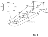
- a plane E4 preferably in the cradle and three levels E1-E3 are preferably in the pipe support.
- the planes each carry four temperature sensors (eg PT 100) which are generally known from the prior art and which are preferably arranged in the region of the corners of the planes.
- the first level E1 near the mouth of the muzzle carries the four sensors p1-p4, the next level in the direction of the cradle E2 carries the sensors p5-p8, etc.
- the sensors are connected to the data box 7 via data lines 6.
- the Databox 7 digitizes the analog signals of the temperature sensors and sends the temperature data via a Datalink 8 to the GCU 9. With this arrangement, it is possible to measure the temperature distribution at pipe cradle 3 and pipe support 4.
- the values of the temperature sensors p1-p16 are digitized and transmitted to the data processing device (GCU 9). At the same time they are compared with the respective storage values of the tube 11. For the temperature-induced pipe deflection, a mathematical model was developed which uses optimization parameters to establish the relationship between the temperature values of the p1-p16 sensors and the overall pipe deflection.
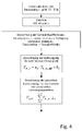
- Fig. 4 The course of the inventive method is summarized in Fig. 4 shown. It will be apparent to those skilled in the art from the general algorithm presented herein without further effort how the compensation of the azimuth error or a hybrid form of these two would have to be configured, so that an explicit statement can be dispensed with here.
- the invention relates equally to the compensation of the azimuth error.
- the numerical weight parameters a, b, g are either entered in advance into the system (GCU) or determined during the measurement and setting up of the gun 10 and incorporated into the mathematical model.
- the temperature values are polynomized to give a length consideration for mapping the tube error.
- the GCU 9 receives from the Databox 7 temperature values T, each with an index for the sensor in question. Thus, averaged temperature differences in elevation of each sensor level E1 to E4 of the pipe support and the cradle are determined. In parallel, it will be determined if and how many of the sensors are functional and deliver plausible values.
- the pipe pitch V for each sensor plane results from the application of the following correlation, where a and b are numerical adjustment parameters. It follows:
- the inherent inertia of the system is additionally taken into account. This is due to the fact that the sensors p1-p16 can indicate much faster temperature changes than this gradient in pipe 11 and pipe support 4 or pipe cradle 3 can compensate.
- a so-called D component is added to the control. This is composed of the first numerical derivative of the aforementioned P-shares of the pipe support 4 and the cradle.
- the total pipe inclination is determined by the sum of the P components and the D components of the pipe support and the cradle.
- V Rohr_El V Rohr_R_P_El + V Rohr_W_P_El + V Rohr_R_D_El + V Rohr_W_D_El wheel
Landscapes
- Engineering & Computer Science (AREA)
- General Engineering & Computer Science (AREA)
- Aiming, Guidance, Guns With A Light Source, Armor, Camouflage, And Targets (AREA)
- Photoreceptors In Electrophotography (AREA)
- Pharmaceuticals Containing Other Organic And Inorganic Compounds (AREA)
- Medicines That Contain Protein Lipid Enzymes And Other Medicines (AREA)
- Measuring Temperature Or Quantity Of Heat (AREA)
- Numerical Control (AREA)
- Automatic Control Of Machine Tools (AREA)
- Machine Tool Sensing Apparatuses (AREA)
- Length Measuring Devices With Unspecified Measuring Means (AREA)
- Pipeline Systems (AREA)
Description
- Die Erfindung betrifft ein Geschützrohr einer Waffe, beispielsweise einer Revolverkanone zum Einsatz in der land- oder seegestützten Flugabwehr. Insbesondere betrifft diese Erfindung ein in einer Rohrwiege und einer Rohrabstützung gelagertes Geschützrohr, wobei die Rohrwiege zur Stabilisierung, Führung und Schwingungsdämpfung in eine Rohrabstützung fortgeführt wird, die das Rohr an mehreren Stellen trägt bzw. abstützt.
- Ein Geschütz umfasst in der Regel eine Unterlafette, einen Turm und eine Rohrwiege mit Rohrabstützung, in der das Rohr gelagert ist (
EP 1 154 219 A ). Bei Sonneneinstrahlung ist die obere Seite der Rohrwiege einer grösseren Temperaturerhöhung ausgesetzt, wohingegen die nicht der Sonneneinstrahlung ausgesetzte untere Seite nur eine geringere Temperaturerhöhung erfährt. Die sich ergebende Thermaldifferenz führt zu einer unterschiedlichen thermalen Ausdehnung zwischen der oberen und der unteren Seite der Rohrwiege, sodass als Resultat ein Rohr mit einer gewissen Länge I sich um einen gewissen Winkel δ an seinem freien Ende aus der ursprünglichen Rohrachse heraus nach unten ausgelenkt wird. Diese Auslenkung hängt stark von den Umgebungs- und Witterungseinflüssen ab und beeinflusst wiederum signifikant die Treffwahrscheinlichkeit der Waffe. - Derartige thermale Unterschiede können auch seitlich auftreten - etwa wenn die Waffe zum Sonnenaufgang oder Sonnenuntergang primär von der Seite Sonnenstrahlung erfährt oder auch durch Wind, der die windzugewandte Geschützseite stärker kühlt als die windabgewandte Seite. Während eines realen Einsatzes werden derartige Effekte in Kombination auftreten.
- Bei jedem Schuss wird das Rohr durch die Explosionsgase beansprucht und gleichzeitig wird durch die mechanische Reibung zwischen Rohr und Projektil Reibungswärme erzeugt. Dies führt zu einer Temperaturerhöhung des Rohrs. Dies ist insbesondere der Fall, wenn die Waffe im Serienfeuer verwendet wird. Dann wird die Wärme am Verschlussende der Waffe und auf der Rohroberseite - wohin die Wärme durch Konvektion übertragen wird - konzentriert. Auch dieser schussbedingte Temperaturgradient führt zu einer Auslenkung des freien Rohrendes aus der Sollposition heraus.
- Einfache passive Lösungen verwenden nach der Lehre der
DE 30 05 117 eine direkt auf das Rohr aufgesetzte Schutzhülle, wobei die Schutzhülle nach der weitergehenden Lehre derDE 199 04 417 nicht radialsymmetrisch ausgeführt ist, um asymmetrischer Erwärmung entgegenzuwirken. - Die
DE 1918 422 offenbart eine Wärmeschutzhülle aus einer das Kanonenrohr in geringem Abstand umgebenden Metallhülle, wobei als Wärmeisolation die ruhende Luftschicht zwischen dem Geschützrohr und der Metallhülle fungiert. Diese Lösungen sind statisch und können nicht auf veränderliche Umgebungsbedingungen reagieren. - Doppelwandige Geschützhüllen führen nach der Lehre der
WO 97 / 47 939 US 4,753,154 ein Arbeitsfluid zwischen den beiden Hüllenflächen entlang, um die Wärmeabfuhr aus dem Schuss zu verbessern. Auch diese Systeme arbeiten ungeregelt und rein passiv. - Aktive Heizelemente direkt auf dem Waffenrohr aufgebracht offenbaren die
DE 32 19 124 sowieGB 2,328,498 - Den schussbedingten Temperaturanstieg misst nach
DE 44 33 627 ein Thermoelement, welches in die Wand des Ladungsraumes per Sackbohrung eingebracht wird. Zum einen wird die mechanische Stabilität durch die Bohrung beeinträchtigt, zum anderen kann kein Temperaturgradient über die Rohrlänge aufgenommen werden. - Der japanische Abstract
JP 7-91891 - Es ist Aufgabe der Erfindung, eine Vorrichtung und ein Verfahren bereitzustellen, mittels derer eine einfache und sehr kostengünstige Kompensation einer thermisch induzierten Rohrverbiegung auch während der Schussabgabe möglich ist.
- Gelöst wird die Aufgabe durch die Merkmale des Patentanspruchs 1 in Hinblick auf die Vorrichtung und Patentanspruch 6 in Hinblick auf das Verfahren. Vorteilhafte Ausgestaltungen sind in den Unteransprüchen aufgezeigt.
- Bekanntlich neigt sich das Waffenrohr bei Sonneneinstrahlung nach unten. Diese Deformation wird durch Temperaturunterschiede zwischen der oberen und unteren Seite der Rohrabstützung und der Wiege verursacht. - Der Effekt der Rohrabstützung und der Effekt der Wiege können grundsätzlich als separate Probleme betrachtet werden; sollten jedoch zur Ermittlung der totalen Rohrneigung superponiert werden.
- Der Erfindung liegt daher die Idee zugrunde, Temperatursensoren einzusetzen und somit ein System zur Temperaturkorrelation zu schaffen. Das System ist dabei technisch in der Lage, Ermittlung der Temperaturdifferenzen zwischen der oberen und unteren Seite der Rohrabstützung (der gegenüberliegenden Sensoren) zu ermitteln sowie zwischen der rechten und linken Seite der Rohrabstützung (der gegenüberliegenden Sensoren). Die Berechnung der Rohrneigung wird mittels der Temperaturdifferenzen durchgeführt. Die Kompensierung der Rohrneigung erfolgt dann über den Inklinationswert, wobei die Kompensierung durch Änderung der Ausrichtung der Rohres in Azimut und / oder Elevation erfolgt. Gleichzeitig kann eine Überwachung der Temperatursensoren und der Databox eingebunden werden.
- Die Temperaturkompensationsfunktion wird als zusätzlicher Parameter in die Waffensteuerung und insbesondere in die Berechnung von Azimut und Elevation der Waffe verwendet. Damit kann eine temperaturbedingte Rohrauslenkung direkt durch die Servomotoren der Waffe kompensiert werden. Damit ist das erfindungsgemässe Verfahren sehr schnell; es regelt mit der üblichen Geschwindigkeit von bis zu mehreren 10° pro Sekunde.
- Gleichzeitig kann das Verfahren während des Schiessens eingesetzt werden. Es ist nicht notwendig, die Waffe aus dem schiessbereiten Zustand in einen nicht schiessbereiten Wartungszustand zu versetzten, um die Rohrkompensation vorzunehmen. Damit erhöht sich die Einsatzdauer der Waffe.
- Für die erfindungsgemässe Vorrichtung sind nur wenige technische Modifikationen vorzunehmen. Im Wesentlichen genügt auf der Hardwareseite die Installation bekannter Temperaturfühler sowie deren Verbindung mit der Databox. Damit ist die Vorrichtung sehr kostengünstig.
- Die Rohrkompensation induziert keine neuen Biegemomente oder Spannungen im Rohr. Damit erhöht sich die Lebensdauer der Waffe.
- Der Ausfall einzelner Sensoren kann über ein mathematisches Modell kompensiert werden, da von einer stetigen Temperaturverteilung in der Rohrwiege und Rohrabstützung ausgegangen werden kann (Plausibilitätscheck). Der Auswertalgorithmus enthält aber diverse Rückfallebenen für den Fall, das mehrere Sensoren ausfallen. Damit ist das System besonders stabil gegenüber dem Ausfall einzelner Sensordaten.
- In Weiterführung der Erfindung wird der zeitliche Verlauf der Temperaturkorrelationsfunktion aufgezeichnet und wird für spätere Wartungsarbeiten auslesbar im Geschützrechner gespeichert. Dadurch kann die thermische Belastung des Geschützes im Nachhinein protokolliert werden oder Fehler im Berechnungsalgorithmus können aufgedeckt werden.
- Entsprechend den militärisch üblichen Temperaturbereichen sind die Sensoren und die Databox für eine funktionstüchtige Arbeitsweise ausgelegt, üblicherweise von -46°C bis +120°C. In diesem Temperaturbereich werden die Messungen mit einer ausreichend hohen Auflösung und Genauigkeit durchgeführt. Auflösung und Genauigkeit ergeben sich aus dem verwendeten mathematischen Modell, eine Auflösung von 0.1°C und eine Genauigkeit von 0.2°C haben sich in der Praxis als ausreichend erwiesen.
- Die vorliegende Idee zeichnet sich somit aus durch:
- sehr einfache Messmethode mit herkömmlichen Temperaturfühlern; das System ist kostengünstig und stabil
- Redundanzen in den Fühlern bei grosser Ausfallsicherheit des Systems gegenüber dem Ausfall einzelner Messfühler
- sehr schnelle Kompensation der Rohrdeformation über Geschützantriebe
- Einsatz während des Schiessens möglich, auch bei Serienfeuer
- Kompensation von Azimutfehlern genauso wie von Elevationsfehlern aufgrund der thermisch induzierten Rohrdeformation
- keine mechanische Beeinträchtigung des Rohrs bzw. der Rohrlagerung durch Messmittel.
- Anhand eines Ausführungsbeispiels mit Zeichnung soll die Erfindung näher erläutert werden. Es zeigt:
-
Fig. 1 einen Geschützturm nach dem Stand der Technik, -
Fig. 2 den Geschütztrum mit der erfindungsgemäßen Vorrichtung in der Rohrwiege und der Rohrabstützung, -
Fig. 3 eine vereinfachte Darstellung der Anordnung der Sensoren ausFig. 2 , -
Fig. 4 eine Blockbilddarstellung des Verfahrens. -
Fig. 1 zeigt ein herkömmliches Revolvergeschützt 10 mit einem Geschützturm 1, einer Unterlafette 2, einer Rohrwiege 3 sowie als Verlängerung der Rohrwiege 3 eine Rohrabstützung 4. Die Rohrabstützung 4 besteht im Wesentlichen aus einem Gitterrohrrahmen (nicht näher dargestellt) und kann, wie das gesamte Geschützt 10 mit einer Schutzhülle (nicht näher dargestellt) verkleidet sein. - Nach
Fig. 2 wird ein derartiges Geschütz 10 mit mehreren Temperatursensoren p1- pn, bevorzugt wird eine Anzahl von 16, im Bereich der Rohrwiege 3 und Rohrabstützung 4 versehen. Mittels der 16 Sensoren (p1-p16) wird bei der Rohrabstützung 4 (zwölf Sensoren) und bei den Wiegenwänden 3 (vier Sensoren) die Temperatur gemessen. Steckerboxen 5 fassen die Signale der Temperatursensoren p1 -p16 aus Rohrabstützung 4 und Wiege 3 zusammen und übertragen diese per Datenverbindungen 6 zur Databox 7, worin die die analogen Signale der Temperatursensoren digitalisiert werden. Anschliessend sendet die Databox 7 die Daten über den Ethernetlink 8 zur GCU 9 (DVS). Die GCU kompensiert dann die Deformation mittels eines Offsets zum Horizont (Inklinationswert-Anpassung). Die Databox 7 umfasst einen Analog/Digitalwandler und einen Server mit Ethernet. - Die Anordnung der Sensoren in Rohrwiege und Rohrabstützung sowie die Verbindung der Komponenten wird nachfolgend beschrieben. - Ausgehend von
Fig. 3 . werden im Wesentlichen senkrecht zur Rohrachse vier Ebenen definiert, wobei eine Ebene E4 bevorzugt in der Rohrwiege und drei Ebenen E1-E3 bevorzugt in der Rohrabstützung liegen. Die Ebenen tragen jeweils vier grundsätzlich aus dem Stand der Technik bekannte Temperatursensoren (z.B. PT 100), welche vorzugsweise im Bereich der Ecken der Ebenen angeordnet sind. Die erste Ebene E1 in der Nähe der Rohrmündung trägt die vier Sensoren p1-p4, die nächste Ebene in Richtung Rohrwiege E2 trägt die Sensoren p5-p8 usw. Die Sensoren sind über Datenleitungen 6 mit der Databox 7 verbunden. Die Databox 7 digitalisiert die analogen Signale der Temperatursensoren und sendet die Temperaturdaten über einen Datalink 8 zur GCU 9. Mit Hilfe dieser Anordnung ist es möglich, die Temperaturverteilung an Rohrwiege 3 und Rohrabstützung 4 zu messen. - Die Werte der Temperaturmessfühler p1-p16 werden digitalisiert und an die Datenverarbeitungseinrichtung (GCU 9) übertragen. Gleichzeitig werden sie mit den jeweiligen Ablagewerten des Rohrs 11 verglichen. Für die temperaturinduzierte Rohrauslenkung wurde ein mathematisches Modell erarbeitet, welches mit Optimierungsparametern den Zusammenhang zwischen den Temperaturwerten der Messfühler p1-p16 und der Gesamt-Rohrauslenkung herstellt.
- Der Ablauf des erfindungsgemässen Verfahrens ist zusammengefasst in
Fig. 4 dargestellt. Für den Fachmann ist aus dem darin dargestellten allgemeinen Algorithmus ohne weitere Anstrengung ersichtlich, wie die Kompensation des Azimut-Fehlers bzw. einer Mischform dieser beiden ausgestaltet sein müsste, sodass auf eine explizite Angabe hier verzichtet werden kann. Die Erfindung bezieht sich in gleicher Weise auf die Kompensation des Azimut-Fehlers. - Die numerischen Gewichtsparameter a, b, g werden vorab entweder in das System (GCU) eingegeben oder beim Vermessen und Einrichtung des Geschützes 10 bestimmt und in das mathematische Modell übernommen.- - Die Temperaturwerte werden polynomisiert, um eine Längenbetrachtung für die Abbildung des Rohrfehlers zu erhalten. Die GCU 9 erhält von der Databox 7 Temperaturwerte T mit jeweils einem Index für den betreffenden Sensor. Damit werden gemittelten Temperaturdifferenzen in Elevation von jeder Sensorebene E1 bis E4 der Rohrabstützung und der Wiege ermittelt. Parallel dazu wird ermittelt, ob und wie viele der Sensoren funktionstüchtig sind und plausible Werte liefern.
-


-



- Anschliessend wird die ermittelte gesamte Rohrneigung wird für jede Sensor-Ebene E1- E4 gewichtet. Dadurch wird die Plausibilitätsüberwachung vereinfacht und um die Modularität zur Berechnung der gesamten Rohrneigung (falls eine Sensor-Ebene ausfällt) zu gewährleistet. Es ergibt sich:


- In einer weiteren Ausführungsform wird zusätzlich die inhärente Trägheit des Systems berücksichtigt. Diese entsteht dadurch, dass die Messfühler p1-p16 wesentlich schneller Temperaturänderungen anzeigen können, als sich dieser Gradient in Rohr 11 und Rohrabstützung 4 bzw. Rohrwiege 3 ausgleichen kann. Zur Berücksichtigung des zeitlichen Messverzuges wird ein sog. D-Anteil zur Steuerung addiert. Dieser setzt sich zusammen aus der ersten numerischen Ableitung der zuvor genannten P-Anteile der Rohrabstützung 4 und der Wiege 3.


- Dieser wird mit den D-Parametern multipliziert.



Claims (14)
- Vorrichtung zur Thermalkompensation eines Waffenrohres (11) eines Geschützes (10) mit wenigstens einem Waffenrohr (11), das in einer Rohrwiege (3) sowie als Verlängerung der Rohrwiege (3) in einer Rohrabstützung (4) gelagert ist, wobei mehrere Temperatursensoren (p1-p16) an der Rohrwiege (3) und der Rohrabstützung (4) eingebunden sind, die über Datenleitungen (6) mit einer Databox (7) und die Databox (7) mit einer Datenverarbeitungseinrichtung (9) verbunden sind, wobei die Datenverarbeitungseinrichtung (9) eine Rohrneigung mittels Temperaturdifferenzen berechnet und zur Thermalkompensation auf Aktuatoren zur Änderung der Ausrichtung des Waffenrohres (11) einwirken kann.
- Vorrichtung nach Anspruch 1, dadurch gekennzeichnet, dass 16 Temperatursensoren (p1-p16) eingebunden sind, wobei Variationen in der Anzahl möglich sind.
- Vorrichtung nach Anspruch 1 oder 2, dadurch gekennzeichnet, dass im Wesentlichen senkrecht zur Rohrachse Ebenen bevorzugt vier Ebenen (e1-E4) definiert werden, wobei vorzugsweise eine Ebene (E4) in der Rohrwiege (3) und vorzugsweise drei Ebenen (E1-E3) in der Rohrabstützung (4) liegen.
- Vorrichtung nach Anspruch 3, dadurch gekennzeichnet, dass die Temperatursensoren (p1-p16) im Bereich der Ecken der Ebenen (E1-E4) angeordnet sind.
- Vorrichtung nach einem der Ansprüche 1 bis 4, dadurch gekennzeichnet, dass die Rohrabstützung (4) gestellartig ist.
- Vorrichtung nach einem der Ansprüche 1 bis 5, dadurch gekennzeichnet, dass die Aktuatoren geschützeigene Stellmotore sind, mit denen das Waffenrohr (1) in Azimut und / oder Elevation ausrichtbar ist.
- Verfahren zur Thermalkompensation eines Waffenrohres (11) eines Geschütztes (10) mit wenigstens einem Waffenrohr (11), das in einer Rohrwiege (3) sowie als Verlängerung der Rohrwiege (3) in einer Rohrabstützung (4) gelagert ist, mit den Schritten:• Messen der Temperatur mittels Temperatursensoren (p1-p16) an der Rohrwiege (3) sowie der Rohrabstützung (4),• Ermitteln der Temperaturdifferenz zwischen der oberen und unteren Seite und der rechten und linken Seite der Rohrwiege (3) als auch der Rohrabstützung (4),• Berechnung der Rohrneigung mittels der ermittelten Temperaturdifferenzen,• Kompensierung der Rohrneigung durch Änderung der Ausrichtung des Waffenrohres (11).
- Verfahren nach Anspruch 7, dadurch gekennzeichnet, dass Temperaturdifferenzen von jeder Sensorebene (E1 bis E4) der Rohrabstützung (4) und der Rohrwiege (3) in Elevation und / oder Azimut ermittelt werden.
- Verfahren nach Anspruch 7 oder 8, dadurch gekennzeichnet, dass die temperaturbedingte Rohrauslenkung direkt durch Aktuatoren, wie geschützeigene Servomotoren der Waffe, kompensiert werden.
- Verfahren nach einem der Ansprüche 7 bis 9, dadurch gekennzeichnet, dass ein Ausfall einzelner Temperatursensoren (p1-p16) über ein mathematisches Modell kompensiert wird.
- Verfahren nach Anspruch 10, dadurch gekennzeichnet, dass der Auswertalgorithmus diverse Rückfallebenen für den Fall enthält, dass mehrere Temperatursensoren (p1-p16) ausfallen.
- Verfahren nach einem der Ansprüche 7 bis 11, dadurch gekennzeichnet, dass auch die inhärente Trägheit des Systems berücksichtigt wird.
- Verfahren nach einem der Ansprüche 7 bis 12, dadurch gekennzeichnet, dass zeitliche Verläufe der Temperaturkorrelationsfunktion aufgezeichnet werden.
- Verfahren nach Anspruch 13, dadurch gekennzeichnet, dass der / die zeitliche(n) Verlauf / Verläufe für spätere Wartungsarbeiten auch auslesbar im Geschützrechner gespeichert werden.
Applications Claiming Priority (2)
| Application Number | Priority Date | Filing Date | Title |
|---|---|---|---|
| DE102011106199A DE102011106199B3 (de) | 2011-06-07 | 2011-06-07 | Vorrichtung und Verfahren zur Thermalkompensation eines Waffenrohres |
| PCT/EP2012/060525 WO2012168200A1 (de) | 2011-06-07 | 2012-06-04 | Vorrichtung und verfahren zur thermalkompensation eines waffenrohres |
Publications (2)
| Publication Number | Publication Date |
|---|---|
| EP2718657A1 EP2718657A1 (de) | 2014-04-16 |
| EP2718657B1 true EP2718657B1 (de) | 2016-05-18 |
Family
ID=46208540
Family Applications (1)
| Application Number | Title | Priority Date | Filing Date |
|---|---|---|---|
| EP12725763.2A Active EP2718657B1 (de) | 2011-06-07 | 2012-06-04 | Vorrichtung und verfahren zur thermalkompensation eines waffenrohres |
Country Status (17)
| Country | Link |
|---|---|
| US (1) | US20140290471A1 (de) |
| EP (1) | EP2718657B1 (de) |
| JP (1) | JP6092853B2 (de) |
| KR (1) | KR101619581B1 (de) |
| CN (1) | CN103582799B (de) |
| BR (1) | BR112013031283B1 (de) |
| CA (1) | CA2837672C (de) |
| DE (1) | DE102011106199B3 (de) |
| DK (1) | DK2718657T3 (de) |
| ES (1) | ES2587515T3 (de) |
| PL (1) | PL2718657T3 (de) |
| RU (1) | RU2560959C2 (de) |
| SA (1) | SA112330601B1 (de) |
| TW (1) | TWI481808B (de) |
| UA (1) | UA107630C2 (de) |
| WO (1) | WO2012168200A1 (de) |
| ZA (1) | ZA201308937B (de) |
Families Citing this family (4)
| Publication number | Priority date | Publication date | Assignee | Title |
|---|---|---|---|---|
| DE102014113593A1 (de) | 2014-09-19 | 2016-03-24 | Rheinmetall Landsysteme Gmbh | Waffentragendes System mit einer Rohrabstützung zur Lagerung des Waffenrohres |
| KR102459305B1 (ko) * | 2021-04-16 | 2022-10-26 | 엘아이지넥스원 주식회사 | 냉각 장치 및 이를 포함하는 포신 냉각 시스템 |
| DE102023122875A1 (de) | 2023-08-25 | 2025-02-27 | Rheinmetall Air Defence Ag | Waffenrohrlagerungssystem und Geschütz mit dem Waffenrohrlagerungssystem |
| DE102023135978A1 (de) | 2023-12-20 | 2025-06-26 | Rheinmetall Air Defence Ag | Geschütz und Verfahren zur Justierung einer Zielvorrichtung eines solchen Geschützes |
Family Cites Families (30)
| Publication number | Priority date | Publication date | Assignee | Title |
|---|---|---|---|---|
| DE1918422A1 (de) * | 1969-04-11 | 1970-10-15 | Wegmann & Co | Waermeschutzhuelle fuer Kanone |
| US3997762A (en) * | 1974-10-09 | 1976-12-14 | David Scarth Ritchie | Fire control system |
| SE441033B (sv) * | 1978-11-02 | 1985-09-02 | Barr & Stroud Ltd | Eldledningsanordning for en kanon |
| US4457206A (en) * | 1979-07-31 | 1984-07-03 | Ares, Inc. | Microwave-type projectile communication apparatus for guns |
| US4283989A (en) * | 1979-07-31 | 1981-08-18 | Ares, Inc. | Doppler-type projectile velocity measurement and communication apparatus, and method |
| DE3005117A1 (de) * | 1980-02-12 | 1981-08-20 | Rheinmetall GmbH, 4000 Düsseldorf | Schutzhuelle fuer ein geschuetzrohr |
| US4448108A (en) * | 1982-05-03 | 1984-05-15 | Fag Kugelfischer Georg Schafer & Co. | Guide system for a gun barrel |
| DE3219124C2 (de) * | 1982-05-21 | 1984-04-19 | Messerschmitt-Bölkow-Blohm GmbH, 8000 München | Waffenrohr mit Schutzmitteln gegen Rohrverzug |
| US4558627A (en) * | 1982-10-29 | 1985-12-17 | General Motors Corporation | Weapon control system |
| US4753154A (en) * | 1984-05-10 | 1988-06-28 | Fuji Electric Corporate Research And Development Ltd. | Gun barrel for tank |
| JPS62190397A (ja) * | 1986-02-17 | 1987-08-20 | 富士電機株式会社 | 砲身の射撃角修正方式 |
| JPH0740871Y2 (ja) * | 1988-05-27 | 1995-09-20 | 防衛庁技術研究本部長 | 自動装填装置 |
| DE3925544A1 (de) * | 1989-08-02 | 1991-02-07 | Rheinmetall Gmbh | Waffenrohrladungsraum mit einer automatischen temperaturkontrollvorrichtung |
| US5267502A (en) * | 1991-05-08 | 1993-12-07 | Sd-Scicon Uk Limited | Weapons systems future muzzle velocity neural network |
| JPH0791891A (ja) * | 1993-09-21 | 1995-04-07 | Japan Steel Works Ltd:The | 射撃方法及び装置 |
| US5413028A (en) * | 1993-11-12 | 1995-05-09 | Cadillac Gage Textron Inc. | Weapon stabilization system |
| FR2724715B1 (fr) * | 1994-09-19 | 1996-12-27 | Giat Ind Sa | Dispositif de reglage en fonction de la temperature exterieure d'un systeme d'equilibrage d'une piece d'artillerie |
| DE4433627C2 (de) * | 1994-09-21 | 1999-01-14 | Rheinmetall Ind Ag | Rohrwaffe mit einem Temperatursensor zur Überwachung der Ladungsraumtemperatur |
| US5726375A (en) * | 1996-06-13 | 1998-03-10 | Mcdonnell Douglas Helicopter | Gun barrel shrouding system |
| US5631437A (en) * | 1996-06-28 | 1997-05-20 | Techno-Sciences, Inc. | Gun muzzle control system using barrel mounted actuator assembly |
| GB2328498A (en) * | 1997-08-22 | 1999-02-24 | Secr Defence | Gun barrel alignment system |
| DE19904417C2 (de) * | 1999-02-04 | 2002-01-03 | Rheinmetall W & M Gmbh | Waffenrohr |
| EP1154219A1 (de) * | 2000-05-11 | 2001-11-14 | Oerlikon Contraves Ag | Verfahren und Vorrichtung zur Korrektur von dynamischen Geschützfehlern |
| AUPR080400A0 (en) * | 2000-10-17 | 2001-01-11 | Electro Optic Systems Pty Limited | Autonomous weapon system |
| CH695248A5 (de) * | 2000-12-19 | 2006-02-15 | Contraves Ag | Verfahren und Vorrichtung zum Korrigieren von Schiessfehlern. |
| DE50204077D1 (de) * | 2002-01-16 | 2005-10-06 | Contraves Ag | Verfahren und Vorrichtung zum Kompensieren von Schiessfehlern und Systemrechner für Waffensystem |
| US7470056B2 (en) * | 2004-02-12 | 2008-12-30 | Industrial Measurement Systems, Inc. | Methods and apparatus for monitoring a condition of a material |
| DE202005006590U1 (de) * | 2005-04-25 | 2006-08-31 | Moog Gmbh | Richt- und Stabilisierungsanlage mit einer Kraftmessvorrichtung zur Drehmomentmessung |
| US8256953B2 (en) * | 2008-10-31 | 2012-09-04 | Yuhas Donald E | Methods and apparatus for measuring temperature and heat flux in a material using ultrasound |
| DE102009042517B4 (de) * | 2009-09-16 | 2024-07-25 | Vincorion Advanced Systems Gmbh | Verfahren und Vorrichtung zur Waffenstabilisierung |
-
2011
- 2011-06-07 DE DE102011106199A patent/DE102011106199B3/de not_active Expired - Fee Related
-
2012
- 2012-04-06 UA UAA201313137A patent/UA107630C2/ru unknown
- 2012-06-04 ES ES12725763.2T patent/ES2587515T3/es active Active
- 2012-06-04 CA CA2837672A patent/CA2837672C/en active Active
- 2012-06-04 RU RU2013158249/11A patent/RU2560959C2/ru active
- 2012-06-04 EP EP12725763.2A patent/EP2718657B1/de active Active
- 2012-06-04 BR BR112013031283-1A patent/BR112013031283B1/pt active IP Right Grant
- 2012-06-04 WO PCT/EP2012/060525 patent/WO2012168200A1/de not_active Ceased
- 2012-06-04 PL PL12725763.2T patent/PL2718657T3/pl unknown
- 2012-06-04 DK DK12725763.2T patent/DK2718657T3/en active
- 2012-06-04 CN CN201280027160.4A patent/CN103582799B/zh active Active
- 2012-06-04 JP JP2014514024A patent/JP6092853B2/ja active Active
- 2012-06-04 KR KR1020137033057A patent/KR101619581B1/ko active Active
- 2012-06-07 TW TW101120542A patent/TWI481808B/zh active
- 2012-06-09 SA SA112330601A patent/SA112330601B1/ar unknown
-
2013
- 2013-11-27 ZA ZA2013/08937A patent/ZA201308937B/en unknown
- 2013-12-09 US US14/100,963 patent/US20140290471A1/en not_active Abandoned
Also Published As
| Publication number | Publication date |
|---|---|
| TWI481808B (zh) | 2015-04-21 |
| RU2013158249A (ru) | 2015-07-20 |
| ZA201308937B (en) | 2014-08-27 |
| JP6092853B2 (ja) | 2017-03-08 |
| DK2718657T3 (en) | 2016-08-15 |
| KR101619581B1 (ko) | 2016-05-10 |
| JP2014521910A (ja) | 2014-08-28 |
| KR20140032436A (ko) | 2014-03-14 |
| RU2560959C2 (ru) | 2015-08-20 |
| SA112330601B1 (ar) | 2016-02-28 |
| CN103582799A (zh) | 2014-02-12 |
| CA2837672C (en) | 2016-08-16 |
| TW201319511A (zh) | 2013-05-16 |
| ES2587515T3 (es) | 2016-10-25 |
| CA2837672A1 (en) | 2012-12-13 |
| DE102011106199B3 (de) | 2012-08-30 |
| UA107630C2 (uk) | 2015-01-26 |
| WO2012168200A1 (de) | 2012-12-13 |
| PL2718657T3 (pl) | 2016-11-30 |
| US20140290471A1 (en) | 2014-10-02 |
| CN103582799B (zh) | 2015-12-23 |
| EP2718657A1 (de) | 2014-04-16 |
| BR112013031283B1 (pt) | 2021-04-20 |
| BR112013031283A2 (pt) | 2016-12-06 |
Similar Documents
| Publication | Publication Date | Title |
|---|---|---|
| EP2047098B1 (de) | Kalibrierverfahren | |
| EP2582972B1 (de) | Verfahren und vorrichtung zur verhinderung einer querschwingung einer windenergieanlage | |
| EP2123588B1 (de) | Kransteuerung mit aktiver Seegangsfolge | |
| DE102010023228B4 (de) | Stabilisierungseinrichtung | |
| EP3527818B1 (de) | Verfahren und system zur kalibrierung eines anemotropometers | |
| DE102011106199B3 (de) | Vorrichtung und Verfahren zur Thermalkompensation eines Waffenrohres | |
| DE102017117837A1 (de) | Laserbearbeitungs-Robotersystem und Laserbearbeitungsverfahren | |
| EP3559446B1 (de) | Verfahren zum steuern einer windenergieanlage | |
| EP3527816B1 (de) | Verfahren und system zum ermitteln einer ausrichtungskorrekturfunktion | |
| DE102007038016A1 (de) | Drehleiter | |
| DE102016103704A1 (de) | Optimalpositionsfinder für energiesparenden Formationsflug | |
| WO2024038124A1 (de) | Computerimplementiertes verfahren und vorrichtung zur justierung von einem blattlastmesssystem eines rotorblatts einer windkraftanlage, windkraftanlage mit zumindest einem rotorblatt mit einem dehnungssensor und computerlesbares speichermedium | |
| EP3367047B1 (de) | Zieleinrichtung | |
| DE112018004704T5 (de) | Sensoranordnung zur Erfassung von Biegemomenten in einem länglichen Bauteil, längliches Bauteil, Sensorsystem und Windenergieanlage | |
| EP1848953B1 (de) | Verfahren zur ermittlung einer feuerleitlösung | |
| DE102014225502A1 (de) | Verfahren und Vorrichtung zur Pitchregelung der Rotorblätter eines Rotors einer Windkraftanlage | |
| DE4317935C2 (de) | Verfahren zur Stabilisierung einer Waffenanlage | |
| DE102019205555A1 (de) | Vorrichtung zur Justage und Montage von Aufzugkomponenten | |
| EP3564591B1 (de) | Verfahren zur erkennung des montageorts eines aussentemperaturfühlers einer heizungsanlage | |
| DE102011115971A1 (de) | Verfahren zur Bestimmung von inertialen Messgrößen | |
| DE102018002982A1 (de) | Vorrichtung und Verfahren zum Steuern einer Windenergieanlage | |
| EP4116576B1 (de) | Verfahren zum erkennen einer extremlast an einer windenergieanlage | |
| EP3278050B1 (de) | System zur justierung der sichtachsen eines gefechtsfahrzeugs sowie verfahren dazu | |
| CH695248A5 (de) | Verfahren und Vorrichtung zum Korrigieren von Schiessfehlern. | |
| DE69813381T2 (de) | Verfahren zum Kontrollieren der seitlichen Streuung von kreiselstabilisierten Geschossen |
Legal Events
| Date | Code | Title | Description |
|---|---|---|---|
| PUAI | Public reference made under article 153(3) epc to a published international application that has entered the european phase |
Free format text: ORIGINAL CODE: 0009012 |
|
| 17P | Request for examination filed |
Effective date: 20131016 |
|
| AK | Designated contracting states |
Kind code of ref document: A1 Designated state(s): AL AT BE BG CH CY CZ DE DK EE ES FI FR GB GR HR HU IE IS IT LI LT LU LV MC MK MT NL NO PL PT RO RS SE SI SK SM TR |
|
| RIN1 | Information on inventor provided before grant (corrected) |
Inventor name: MEIER, RAFFAEL Inventor name: BRUNNER, DOMINIC |
|
| DAX | Request for extension of the european patent (deleted) | ||
| 17Q | First examination report despatched |
Effective date: 20150331 |
|
| GRAP | Despatch of communication of intention to grant a patent |
Free format text: ORIGINAL CODE: EPIDOSNIGR1 |
|
| INTG | Intention to grant announced |
Effective date: 20151204 |
|
| GRAS | Grant fee paid |
Free format text: ORIGINAL CODE: EPIDOSNIGR3 |
|
| GRAA | (expected) grant |
Free format text: ORIGINAL CODE: 0009210 |
|
| AK | Designated contracting states |
Kind code of ref document: B1 Designated state(s): AL AT BE BG CH CY CZ DE DK EE ES FI FR GB GR HR HU IE IS IT LI LT LU LV MC MK MT NL NO PL PT RO RS SE SI SK SM TR |
|
| REG | Reference to a national code |
Ref country code: GB Ref legal event code: FG4D Free format text: NOT ENGLISH |
|
| REG | Reference to a national code |
Ref country code: CH Ref legal event code: EP |
|
| REG | Reference to a national code |
Ref country code: IE Ref legal event code: FG4D Free format text: LANGUAGE OF EP DOCUMENT: GERMAN Ref country code: AT Ref legal event code: REF Ref document number: 800866 Country of ref document: AT Kind code of ref document: T Effective date: 20160615 |
|
| REG | Reference to a national code |
Ref country code: FR Ref legal event code: PLFP Year of fee payment: 5 |
|
| REG | Reference to a national code |
Ref country code: DE Ref legal event code: R096 Ref document number: 502012007166 Country of ref document: DE |
|
| REG | Reference to a national code |
Ref country code: CH Ref legal event code: NV Representative=s name: WEINMANN ZIMMERLI, CH |
|
| REG | Reference to a national code |
Ref country code: SE Ref legal event code: TRGR |
|
| REG | Reference to a national code |
Ref country code: DK Ref legal event code: T3 Effective date: 20160809 |
|
| REG | Reference to a national code |
Ref country code: RO Ref legal event code: EPE |
|
| REG | Reference to a national code |
Ref country code: NL Ref legal event code: FP |
|
| REG | Reference to a national code |
Ref country code: LT Ref legal event code: MG4D |
|
| REG | Reference to a national code |
Ref country code: ES Ref legal event code: FG2A Ref document number: 2587515 Country of ref document: ES Kind code of ref document: T3 Effective date: 20161025 |
|
| PG25 | Lapsed in a contracting state [announced via postgrant information from national office to epo] |
Ref country code: FI Free format text: LAPSE BECAUSE OF FAILURE TO SUBMIT A TRANSLATION OF THE DESCRIPTION OR TO PAY THE FEE WITHIN THE PRESCRIBED TIME-LIMIT Effective date: 20160518 Ref country code: LT Free format text: LAPSE BECAUSE OF FAILURE TO SUBMIT A TRANSLATION OF THE DESCRIPTION OR TO PAY THE FEE WITHIN THE PRESCRIBED TIME-LIMIT Effective date: 20160518 Ref country code: NO Free format text: LAPSE BECAUSE OF FAILURE TO SUBMIT A TRANSLATION OF THE DESCRIPTION OR TO PAY THE FEE WITHIN THE PRESCRIBED TIME-LIMIT Effective date: 20160818 |
|
| PG25 | Lapsed in a contracting state [announced via postgrant information from national office to epo] |
Ref country code: RS Free format text: LAPSE BECAUSE OF FAILURE TO SUBMIT A TRANSLATION OF THE DESCRIPTION OR TO PAY THE FEE WITHIN THE PRESCRIBED TIME-LIMIT Effective date: 20160518 Ref country code: PT Free format text: LAPSE BECAUSE OF FAILURE TO SUBMIT A TRANSLATION OF THE DESCRIPTION OR TO PAY THE FEE WITHIN THE PRESCRIBED TIME-LIMIT Effective date: 20160919 Ref country code: LV Free format text: LAPSE BECAUSE OF FAILURE TO SUBMIT A TRANSLATION OF THE DESCRIPTION OR TO PAY THE FEE WITHIN THE PRESCRIBED TIME-LIMIT Effective date: 20160518 Ref country code: HR Free format text: LAPSE BECAUSE OF FAILURE TO SUBMIT A TRANSLATION OF THE DESCRIPTION OR TO PAY THE FEE WITHIN THE PRESCRIBED TIME-LIMIT Effective date: 20160518 |
|
| PG25 | Lapsed in a contracting state [announced via postgrant information from national office to epo] |
Ref country code: BE Free format text: LAPSE BECAUSE OF NON-PAYMENT OF DUE FEES Effective date: 20160630 |
|
| PG25 | Lapsed in a contracting state [announced via postgrant information from national office to epo] |
Ref country code: CZ Free format text: LAPSE BECAUSE OF FAILURE TO SUBMIT A TRANSLATION OF THE DESCRIPTION OR TO PAY THE FEE WITHIN THE PRESCRIBED TIME-LIMIT Effective date: 20160518 Ref country code: EE Free format text: LAPSE BECAUSE OF FAILURE TO SUBMIT A TRANSLATION OF THE DESCRIPTION OR TO PAY THE FEE WITHIN THE PRESCRIBED TIME-LIMIT Effective date: 20160518 Ref country code: SK Free format text: LAPSE BECAUSE OF FAILURE TO SUBMIT A TRANSLATION OF THE DESCRIPTION OR TO PAY THE FEE WITHIN THE PRESCRIBED TIME-LIMIT Effective date: 20160518 |
|
| REG | Reference to a national code |
Ref country code: GR Ref legal event code: EP Ref document number: 20160401632 Country of ref document: GR Effective date: 20161020 |
|
| REG | Reference to a national code |
Ref country code: DE Ref legal event code: R082 Ref document number: 502012007166 Country of ref document: DE Representative=s name: HUEBSCH & WEIL PATENT- UND RECHTSANWALTSKANZLE, DE Ref country code: DE Ref legal event code: R082 Ref document number: 502012007166 Country of ref document: DE Representative=s name: HUEBSCH, KIRSCHNER & PARTNER, PATENTANWAELTE U, DE Ref country code: DE Ref legal event code: R082 Ref document number: 502012007166 Country of ref document: DE Ref country code: DE Ref legal event code: R097 Ref document number: 502012007166 Country of ref document: DE |
|
| PG25 | Lapsed in a contracting state [announced via postgrant information from national office to epo] |
Ref country code: SM Free format text: LAPSE BECAUSE OF FAILURE TO SUBMIT A TRANSLATION OF THE DESCRIPTION OR TO PAY THE FEE WITHIN THE PRESCRIBED TIME-LIMIT Effective date: 20160518 |
|
| REG | Reference to a national code |
Ref country code: IE Ref legal event code: MM4A |
|
| PLBE | No opposition filed within time limit |
Free format text: ORIGINAL CODE: 0009261 |
|
| STAA | Information on the status of an ep patent application or granted ep patent |
Free format text: STATUS: NO OPPOSITION FILED WITHIN TIME LIMIT |
|
| PG25 | Lapsed in a contracting state [announced via postgrant information from national office to epo] |
Ref country code: MC Free format text: LAPSE BECAUSE OF FAILURE TO SUBMIT A TRANSLATION OF THE DESCRIPTION OR TO PAY THE FEE WITHIN THE PRESCRIBED TIME-LIMIT Effective date: 20160518 |
|
| REG | Reference to a national code |
Ref country code: DE Ref legal event code: R082 Ref document number: 502012007166 Country of ref document: DE Representative=s name: HUEBSCH, KIRSCHNER & PARTNER, PATENTANWAELTE U, DE |
|
| 26N | No opposition filed |
Effective date: 20170221 |
|
| GBPC | Gb: european patent ceased through non-payment of renewal fee |
Effective date: 20160818 |
|
| PG25 | Lapsed in a contracting state [announced via postgrant information from national office to epo] |
Ref country code: IE Free format text: LAPSE BECAUSE OF NON-PAYMENT OF DUE FEES Effective date: 20160604 Ref country code: SI Free format text: LAPSE BECAUSE OF FAILURE TO SUBMIT A TRANSLATION OF THE DESCRIPTION OR TO PAY THE FEE WITHIN THE PRESCRIBED TIME-LIMIT Effective date: 20160518 |
|
| REG | Reference to a national code |
Ref country code: FR Ref legal event code: PLFP Year of fee payment: 6 |
|
| PG25 | Lapsed in a contracting state [announced via postgrant information from national office to epo] |
Ref country code: GB Free format text: LAPSE BECAUSE OF NON-PAYMENT OF DUE FEES Effective date: 20160818 |
|
| PG25 | Lapsed in a contracting state [announced via postgrant information from national office to epo] |
Ref country code: HU Free format text: LAPSE BECAUSE OF FAILURE TO SUBMIT A TRANSLATION OF THE DESCRIPTION OR TO PAY THE FEE WITHIN THE PRESCRIBED TIME-LIMIT; INVALID AB INITIO Effective date: 20120604 Ref country code: CY Free format text: LAPSE BECAUSE OF FAILURE TO SUBMIT A TRANSLATION OF THE DESCRIPTION OR TO PAY THE FEE WITHIN THE PRESCRIBED TIME-LIMIT Effective date: 20160518 |
|
| REG | Reference to a national code |
Ref country code: FR Ref legal event code: PLFP Year of fee payment: 7 |
|
| PG25 | Lapsed in a contracting state [announced via postgrant information from national office to epo] |
Ref country code: LU Free format text: LAPSE BECAUSE OF NON-PAYMENT OF DUE FEES Effective date: 20160604 Ref country code: MT Free format text: LAPSE BECAUSE OF FAILURE TO SUBMIT A TRANSLATION OF THE DESCRIPTION OR TO PAY THE FEE WITHIN THE PRESCRIBED TIME-LIMIT Effective date: 20160518 Ref country code: MK Free format text: LAPSE BECAUSE OF FAILURE TO SUBMIT A TRANSLATION OF THE DESCRIPTION OR TO PAY THE FEE WITHIN THE PRESCRIBED TIME-LIMIT Effective date: 20160518 Ref country code: IS Free format text: LAPSE BECAUSE OF FAILURE TO SUBMIT A TRANSLATION OF THE DESCRIPTION OR TO PAY THE FEE WITHIN THE PRESCRIBED TIME-LIMIT Effective date: 20160518 |
|
| PG25 | Lapsed in a contracting state [announced via postgrant information from national office to epo] |
Ref country code: BG Free format text: LAPSE BECAUSE OF FAILURE TO SUBMIT A TRANSLATION OF THE DESCRIPTION OR TO PAY THE FEE WITHIN THE PRESCRIBED TIME-LIMIT Effective date: 20160518 |
|
| REG | Reference to a national code |
Ref country code: AT Ref legal event code: MM01 Ref document number: 800866 Country of ref document: AT Kind code of ref document: T Effective date: 20170604 |
|
| PG25 | Lapsed in a contracting state [announced via postgrant information from national office to epo] |
Ref country code: AL Free format text: LAPSE BECAUSE OF FAILURE TO SUBMIT A TRANSLATION OF THE DESCRIPTION OR TO PAY THE FEE WITHIN THE PRESCRIBED TIME-LIMIT Effective date: 20160518 |
|
| PG25 | Lapsed in a contracting state [announced via postgrant information from national office to epo] |
Ref country code: AT Free format text: LAPSE BECAUSE OF NON-PAYMENT OF DUE FEES Effective date: 20170604 |
|
| REG | Reference to a national code |
Ref country code: DE Ref legal event code: R082 Ref document number: 502012007166 Country of ref document: DE Representative=s name: HUEBSCH, KIRSCHNER & PARTNER, PATENTANWAELTE U, DE |
|
| PGFP | Annual fee paid to national office [announced via postgrant information from national office to epo] |
Ref country code: DE Payment date: 20250618 Year of fee payment: 14 Ref country code: PL Payment date: 20250523 Year of fee payment: 14 |
|
| PGFP | Annual fee paid to national office [announced via postgrant information from national office to epo] |
Ref country code: DK Payment date: 20250625 Year of fee payment: 14 |
|
| PGFP | Annual fee paid to national office [announced via postgrant information from national office to epo] |
Ref country code: NL Payment date: 20250618 Year of fee payment: 14 |
|
| PGFP | Annual fee paid to national office [announced via postgrant information from national office to epo] |
Ref country code: FR Payment date: 20250624 Year of fee payment: 14 |
|
| PGFP | Annual fee paid to national office [announced via postgrant information from national office to epo] |
Ref country code: GR Payment date: 20250620 Year of fee payment: 14 |
|
| PGFP | Annual fee paid to national office [announced via postgrant information from national office to epo] |
Ref country code: RO Payment date: 20250527 Year of fee payment: 14 |
|
| PGFP | Annual fee paid to national office [announced via postgrant information from national office to epo] |
Ref country code: TR Payment date: 20250527 Year of fee payment: 14 |
|
| PGFP | Annual fee paid to national office [announced via postgrant information from national office to epo] |
Ref country code: SE Payment date: 20250618 Year of fee payment: 14 |
|
| PGFP | Annual fee paid to national office [announced via postgrant information from national office to epo] |
Ref country code: ES Payment date: 20250728 Year of fee payment: 14 |
|
| PGFP | Annual fee paid to national office [announced via postgrant information from national office to epo] |
Ref country code: IT Payment date: 20250624 Year of fee payment: 14 |
|
| PGFP | Annual fee paid to national office [announced via postgrant information from national office to epo] |
Ref country code: CH Payment date: 20250701 Year of fee payment: 14 |