EP2718588B1 - Dispositif d'amortissement de torsion, notamment pour une transmission de vehicule automobile - Google Patents
Dispositif d'amortissement de torsion, notamment pour une transmission de vehicule automobile Download PDFInfo
- Publication number
- EP2718588B1 EP2718588B1 EP12725052.0A EP12725052A EP2718588B1 EP 2718588 B1 EP2718588 B1 EP 2718588B1 EP 12725052 A EP12725052 A EP 12725052A EP 2718588 B1 EP2718588 B1 EP 2718588B1
- Authority
- EP
- European Patent Office
- Prior art keywords
- pendulum
- oscillator
- washer
- mass
- turbine
- Prior art date
- Legal status (The legal status is an assumption and is not a legal conclusion. Google has not performed a legal analysis and makes no representation as to the accuracy of the status listed.)
- Not-in-force
Links
Images


Classifications
-
- F—MECHANICAL ENGINEERING; LIGHTING; HEATING; WEAPONS; BLASTING
- F16—ENGINEERING ELEMENTS AND UNITS; GENERAL MEASURES FOR PRODUCING AND MAINTAINING EFFECTIVE FUNCTIONING OF MACHINES OR INSTALLATIONS; THERMAL INSULATION IN GENERAL
- F16F—SPRINGS; SHOCK-ABSORBERS; MEANS FOR DAMPING VIBRATION
- F16F15/00—Suppression of vibrations in systems; Means or arrangements for avoiding or reducing out-of-balance forces, e.g. due to motion
- F16F15/10—Suppression of vibrations in rotating systems by making use of members moving with the system
- F16F15/14—Suppression of vibrations in rotating systems by making use of members moving with the system using masses freely rotating with the system, i.e. uninvolved in transmitting driveline torque, e.g. rotative dynamic dampers
- F16F15/1407—Suppression of vibrations in rotating systems by making use of members moving with the system using masses freely rotating with the system, i.e. uninvolved in transmitting driveline torque, e.g. rotative dynamic dampers the rotation being limited with respect to the driving means
- F16F15/145—Masses mounted with play with respect to driving means thus enabling free movement over a limited range
-
- F—MECHANICAL ENGINEERING; LIGHTING; HEATING; WEAPONS; BLASTING
- F16—ENGINEERING ELEMENTS AND UNITS; GENERAL MEASURES FOR PRODUCING AND MAINTAINING EFFECTIVE FUNCTIONING OF MACHINES OR INSTALLATIONS; THERMAL INSULATION IN GENERAL
- F16F—SPRINGS; SHOCK-ABSORBERS; MEANS FOR DAMPING VIBRATION
- F16F15/00—Suppression of vibrations in systems; Means or arrangements for avoiding or reducing out-of-balance forces, e.g. due to motion
- F16F15/10—Suppression of vibrations in rotating systems by making use of members moving with the system
- F16F15/12—Suppression of vibrations in rotating systems by making use of members moving with the system using elastic members or friction-damping members, e.g. between a rotating shaft and a gyratory mass mounted thereon
- F16F15/121—Suppression of vibrations in rotating systems by making use of members moving with the system using elastic members or friction-damping members, e.g. between a rotating shaft and a gyratory mass mounted thereon using springs as elastic members, e.g. metallic springs
- F16F15/123—Wound springs
-
- F—MECHANICAL ENGINEERING; LIGHTING; HEATING; WEAPONS; BLASTING
- F16—ENGINEERING ELEMENTS AND UNITS; GENERAL MEASURES FOR PRODUCING AND MAINTAINING EFFECTIVE FUNCTIONING OF MACHINES OR INSTALLATIONS; THERMAL INSULATION IN GENERAL
- F16F—SPRINGS; SHOCK-ABSORBERS; MEANS FOR DAMPING VIBRATION
- F16F15/00—Suppression of vibrations in systems; Means or arrangements for avoiding or reducing out-of-balance forces, e.g. due to motion
- F16F15/10—Suppression of vibrations in rotating systems by making use of members moving with the system
- F16F15/14—Suppression of vibrations in rotating systems by making use of members moving with the system using masses freely rotating with the system, i.e. uninvolved in transmitting driveline torque, e.g. rotative dynamic dampers
Definitions
- the invention relates to a torsion damping device, especially for a motor vehicle transmission.
- damping devices of this type are known from the state of the art, generally fitted to a motor vehicle transmission as disclosed, for example, in the document US 2010/0269497 A1 .
- such a torsion damping device is associated with a clutch capable of selectively connecting the engine to the gearbox, such as a friction clutch or a hydrokinetic coupling apparatus comprising a clutch. locking, and this in order to filter the vibrations due to motor acyclisms.
- an internal combustion engine has acyclisms due to successive explosions in the cylinders of the engine, said acyclisms varying in particular according to the number of cylinders.
- the damping means of a torsion damping device therefore have the function of filtering the vibrations generated by the acyclisms and intervene before the engine torque has been transmitted to the gearbox.
- a pendulum oscillator also called pendulum, comprises at least one mass or flyweight, generally several, arranged around the axis of rotation of the drive shaft and which is free to oscillate about a fictitious axis substantially parallel to the axis of rotation of the motor shaft.
- the object of the present invention is particularly to provide a damping device to further improve the results obtained including a small footprint.
- the invention proposes a torsion damping device of the type described above, characterized in that the damping device comprises at least two pendular oscillators, the first washer comprising at least a first pendulum oscillator and the second washer. having at least a second pendulum oscillator.
- the damping device improves the filtration of the vibrations and the pendular oscillators are advantageously carried by the washers of the damping device which respectively provide, with respect to the elastic members, a phasing function on the one hand, and a guidance function on the other hand.
- such a washer providing a dual phasing and guiding function makes it possible to reduce the number of parts of the damping device and to optimize the axial size of the device.
- said washers of the damping device are arranged axially at the front and rear ends of the damping device so as to be spaced apart from each other by the greatest distance possible for a given axial dimension of the damping device. .
- the masses of each of the first and second pendular oscillators can be maximum, in particular when said masses of the first and second pendular oscillators are arranged on the same diameter with respect to the X axis.
- said washers of the damping device are parts that are able to withstand the masses of pendulum oscillators and allow to obtain a particularly compact damping device both axially and radially.
- the damping device equips a hydrokinetic coupling apparatus comprising a turbine and the input element of the damping device is rotatably connected to the turbine.
- the turbine is rotatably connected to a turbine hub and to the second input disk by fastening means, such as rivets.
- the damping device equipping a hydrokinetic coupling apparatus comprising a turbine, at least the second washer carrying the second pendulum oscillator is rotatably connected to the turbine.
- the turbine is rotatably connected to the second washer via fastening means, such as rivets.
- the damping device according to the invention equipping a hydrokinetic coupling apparatus comprising a turbine, the output element of the damping device is connected in rotation to the turbine, directly or via a turbine hub.
- the turbine is rotatably connected to the turbine hub by fastening means, such as rivets, and the turbine hub is rotatably connected by coupling means directly to the driven shaft or via an output hub of the damping device.
- the coupling means between the turbine hub and the output hub of the damping device are formed by cooperation of shapes, in particular by means of complementary grooves which respectively comprise the turbine hub and the output hub.
- the coupling means between the turbine hub and the output hub of the damping device are formed by keys.
- the "axial" orientation corresponds to the axis of rotation of the damping device and the direction from front to rear corresponds to that indicated by the arrow "a" on the figure 1 , respectively the left and the right on the figure 1 .
- the "radial” orientation is directed orthogonally to the axis of rotation of the damping device from the inside towards the outside away from said axis and the "circumferential" orientation is directed orthogonal to the axis of the device damping and orthogonal to the radial direction.
- FIG. 1 a torsion damping device 10 according to the invention which is suitable for equipping a motor vehicle transmission.
- the damping device 10 is in particular, but not exclusively, intended to equip a hydrokinetic coupling device.
- such a hydrokinetic coupling device mainly comprises a locking clutch (or "lock-up" in English), a damping device and a coupler or, preferably, a converter.
- the hydrokinetic coupling apparatus comprises a sealed casing formed respectively of a front portion and a rear portion, generally in the form of shells which are for example assembled by welding.
- the front and rear parts of the housing define a general volume of the apparatus within which the locking clutch, the damping device and the torque converter are arranged axially from front to rear.
- the torque converter comprises a rear impeller wheel, a front turbine wheel and a central reaction wheel.
- the impeller wheel comprises vanes which are carried by the rear part of the casing which, integral in rotation with the front part of the casing, is able to be connected in rotation to a driving shaft.
- the turbine wheel also comprises vanes which axially face the blades of the impeller wheel, the turbine wheel is adapted to be rotatably connected to a driven shaft, coaxial with the axis of rotation of the damping device, for example via a hub.
- the driving shaft is constituted by the crankshaft of the internal combustion engine of the motor vehicle, while the driven shaft is constituted by the input shaft of the gearbox. of the vehicle, connected to the gearshift means.
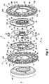
- the damping device 10 has an axis X of rotation which extends, by convention, according to the axial orientation.
- the damping device 10 comprises at least one input element 12, a output member 14 and circumferentially acting elastic members 16 which are interposed between the input member 12 and the output member 14.
- the input element 12 is intended to be rotated by a drive shaft (not shown), such as the crankshaft of the internal combustion engine of the motor vehicle equipped with a transmission including the clutch, which comprises the said device 10 in the example of application is a hydrokinetic coupling device of the type described above.
- the output element 14 is intended to be rotatably connected to a driven shaft (not shown), such as the input shaft of the gearbox.
- the input element 12 comprises a first input disk 12A and a second input disk 12B respectively arranged axially at the front and at the rear of the damping device 10 and the output element 14 comprises at least one web 22, arranged axially in a central position between said first and second disks 12A, 12B.
- the web 22 is here made in one piece, alternatively the web 22 is made of two separate parts, arranged parallel to each other in the central position of the damping device 10.
- first input disk 12A and the second input disk 12B are connected in rotation by connecting means 18, 20.
- connection means in rotation of the first input disk 12A and the second input disk 12B are for example constituted by at least one axial lug 18 which, integral with the one 12A of the disks, is received in a complementary opening 20 arranged in the other 12B disks.
- connection means of the discs 12A, 12B comprise three tabs 18 which are distributed circumferentially in a regular manner on the first disc 12A arranged axially at the front, ie at 120 ° around the axis X of rotation of the device 10 amortization.
- the second disk 12B arranged axially at the rear also has three openings 20 circumferentially distributed regularly at 120 ° around the axis X of rotation of the damping device 10.
- the tabs 18 which extend axially rearwardly from the first disk 12A provide a spacer function and participate in the proper positioning of the parts, in particular the first and second disks 12A, 12B input relative to the web 22 of the output element 14 of the damping device 10 which is interposed axially between said input disks 12A, 12B.
- the damping device 10 further comprises at least two washers, respectively a first washer 24A and a second washer 24B.
- the first washer 24A and the second washer 24B are able to cooperate with the elastic members 16.
- the torque is transmitted via the elastic members 16 with circumferential action of the disks 12A and 12B forming the input element, the web 22 forming here a portion of the element 14 output .
- the first and second input discs 12A, 12B each have windows 26 and the web 22 has windows 28, the elastic members 16 with circumferential action respectively received in said windows 26 and 28 thus being interposed between the element 12 of input and the output element 14.
- the windows 26 and 28 are for example three in number distributed circumferentially in a regular manner around the axis X of rotation of the damping device 10.
- the windows 26 of the inlet discs 12A, 12B are closed and respectively delimited, on the one hand, by an inner edge and an outer edge 32 which extend respectively circumferentially and, on the other hand, by two edges 34 extending respectively radially and each of which connects an end of the inner edge 30 and the outer edge 32 together.
- the three windows 26 are interconnected by portions of material at which the connecting lugs 18 of the inlet discs 12A, 12B are arranged at the outer radial periphery so that each lug 18 or opening 20 is arranged circumferentially between two consecutive windows 26.
- the windows 28 of the web 22 of the output element 14 are open radially outwards and the windows 28 are separated from each other by three lugs 26 arranged in a star, distributed circumferentially at 120 °, each of the lugs 36 having two edges 38 opposed with which cooperate respectively an end of one of the elastic members 16 circumferential action.
- each window 26, 28 receives two elastic members 16 with circumferential action and not only one so that said elastic members 16 are in the embodiment example of six, distributed circumferentially in three groups of two elastic members 16.
- the elastic members 16 are for example formed by helical springs having a main axis of circumferential orientation. As can be seen in figure 1 , the elastic members 16 are arranged in a circular row around the veil 22 in particular.
- a group of two elastic members 16 has advantages over the use of a single bent resilient member 16 of equivalent length, in particular a better biasing of the elastic members 16 substantially along their main axis and a lower sensitivity to the radial forces exerted by centrifugal force.
- the two elastic members 16 forming a group must be interconnected in order to operate in series.
- each of the first and second washers 24A and 24B comprises phasing means 40 able to connect together two elastic members 16 housed in the same window 26 of the inlet discs 12A, 12B and the same window 28 of the web 22.
- the first and second washers 24A and 24B comprise windows 42, here three in number, two consecutive windows 42 being separated from each other by a phasing means 40.
- the windows 42 of the first and second washers 24A and 24B are angularly offset with respect to the windows 26 and 28 so that the phasing means 40 are positioned between two elastic members 16, each phasing means 40 having two opposite orientation edges 44. radial which each cooperate with one of the two elastic members 16 of a group.
- the first washer 24A and the second washer 24B are mounted free to rotate relative to the input elements 12 and 14 output.
- the axial distance between the two washers 24A and 24B is smaller than the diameter of the elastic members 16.
- the first washer 24A and the second washer 24B also provide, in addition to a phasing function of the elastic members 16 with circumferential action, a guiding function.
- the guiding function of the elastic members 16 with circumferential action is provided by other additional and distinct parts of the first washer 24A and the second washer 24B.
- the embodiment shown in the figures is particularly advantageous when the first washer 24A and the second washer 24B provide the phasing function and the function of guidance whereby, in addition to the reduced number of parts, the damping device 10 is especially less bulky axially.
- the first washer 24A and the second washer 24B respectively comprise, at the level of the windows 42, guide means 46 capable of holding in position the resilient members 16 with circumferential action, both axially and radially.
- the elastic members 16 with circumferential action are in particular stressed in operation by forces due to the centrifugal force acting in the radial direction.
- the first input disk 12A is able to be connected in rotation, via a connecting piece 48, to a clutch lock (not shown).
- the connecting piece 48 has, in axial section, an inverted "L" shape comprising a radially oriented branch and an axially oriented branch extending forwards from the outer part of the branch radial orientation.
- the second input disk 12B is rotatably connected to a turbine 50 of the converter, the turbine 50 being represented on the only Figures 5 to 11 .
- the locking clutch being in the disengaged (open) state, the torque is first transmitted by the converter, more specifically by the turbine 50 to the second disk 12B through which the torque enters the device 10. damping before being transmitted by the veil 22.
- the locking clutch comprising said connecting piece 48 is of multi-disk type.
- the locking clutch comprising said connecting piece 48 is of mono- or bi-disk type.
- the locking clutch (not shown) comprises a piston which is able to be selectively controlled in displacement to tighten or not friction discs rotatably connected to the connecting piece 48 and thus cause the changes of state of the clutch, between the disengaged and engaged state.
- the damping device 10 comprises a flange 52 which is interposed axially between the first input disk 12A and said connecting piece 48, in the vicinity of the radially inner portion of the first input disk 12A and said part. 48 link.
- the flange 52 is removed and the connecting piece 48 is shaped to come into direct contact with the first input disk 12A.
- such a flange 52 simplifies the manufacture of the connecting piece 48 and strengthen the connection between the first input disk 12A and the connecting piece 48 between which the flange 52 is interposed axially.
- connection between the first input disk 12A and the connecting piece 48 of the locking clutch, as well as the flange 52 when the damping device 10 comprises such a flange 52, is produced via means 54. of fixation.
- the fixing means 54 consist of rivets, alternatively by any other suitable connecting means.
- the damping device 10 comprises an outlet hub 56 through which the web 22 is adapted to be rotatably connected to the driven shaft.
- the web 22 is fixed by welding to the outlet hub 56 to link in rotation, without play, these two parts forming said output member 14 of the damping device 10.
- connection in rotation between the web 22 and the outlet hub 56 is made by friction welding.
- connection in rotation between the web 22 and the outlet hub 56 is made by any appropriate means for example by cooperation of shapes, such as by meshing between complementary teeth.
- the input element 12 and the output element 14 of the damping device 10 are connected in rotation with an angular displacement which is limited by means 58 of abutment.
- the means 58 for abutment of the damping device 10 consist of at least one spacer intervening between the first and second inlet discs 12A and 12B and the web 22.
- the abutment means 58 consist, for example, of three spacers angularly distributed uniformly over the circumference of the first and second inlet discs 12A and 12B.
- Each spacer 58 comprises a central section 60 which is received in an associated opening 62 of the web 22, the opening 62 determining the angular displacement capacity between the input and output elements 12 when the central section 60 of the spacer 58 abuts at one end of the opening 62.
- first washer 24A and the second washer 24B are connected in rotation by connecting means 64.
- the connecting means 64 between the first washer 24A and the second washer 24B are constituted by spacers which are more particularly visible on the figure 7 .
- the second input disk 12B is rotatably connected to the turbine 50 of the converter.
- the damping device 10 comprises a turbine hub 66.
- the second inlet disk 12B, the turbine hub 66 and the turbine 50 are rotatably connected by fixing means 68.
- the connecting means 68 are constituted by rivets which connect together the second inlet disk 12B, the turbine hub 66 and the turbine 50.
- the spacers 58 forming the abutment means also provide at each of their ends a connecting function, axially at the front between the first input disk 12A, the flange 52 and the connecting piece 48 and, axially at the rear between the second inlet disk 12B, the turbine hub 66 and the turbine 50.
- each spacer 58 replaces respectively a rivet 54 at the front and a rivet 68 at the rear.
- the damping device 10 comprises first torsion damping means formed by the elastic members 16 with circumferential action and second torsion damping means formed by at least one pendulum oscillator or pendulum.
- said first torsion damping means comprise a single row of elastic members 16 circumferentially distributed around the axis X of rotation of the damping device 10.
- said first torsion damping means comprise two rows of elastic members 16 radially offset with respect to each other, the elastic members 16 of each of the rows (or floor) preferably having different stiffnesses.
- the damping device 10 comprises at least two oscillatory oscillators forming second torsion damping means of the damping device 10.
- the damping device 10 comprises at least two pendular oscillators, here a double pendulum oscillator.
- the damping device 10 comprises respectively at least a first pendular oscillator P1 carried by the first washer 24A and at least a second pendular oscillator P2 carried by the second washer 24B.
- each of the washers 24A, 24B comprises a pendulum oscillator characterized by its order of agreement.
- At least one of the washers 24A, 24B comprises more than one pendulum oscillator, that is to say at least one primary pendulum oscillator and a secondary pendulum oscillator, each characterized respectively by an order agree different from that of the other.
- the first oscillating oscillator P1 comprises at least one pendular mass M n oscillatingly mounted relative to the first washer 24A and the second pendular oscillator P2 comprises at least one pendular mass M n + 1 mounted oscillatingly with respect to the second washer. 24B.
- a four-cylinder engine causes vibrations that have a given frequency harmonic having different harmonic ranks.
- the first pendulum oscillator P1 and the second pendulum oscillator P2 are tuned differently, respectively according to a first tuning order for the first oscillator P1 pendulum and according to a second tuning order for the second oscillator P2 pendular.
- each of the first and second pendulums P1, P2 carried by one associated with the washers 24A, 24B thus has a given order of agreement corresponding to a given harmonic rank.
- the vibrations of a harmonic of frequency 2F0 are advantageously able to be filtered by a first pendular oscillator P1 having an order of agreement equal to the order " 2 "and by a second oscillator P2 pendulum having an order of agreement equal to the order "4".
- the first oscillator P1 advantageously has a tuning order equal to the order "3" and the second pendulum oscillator P2 a tuning order equal to the order "6" .
- the vibrations to be filtered sometimes have a predominant harmonic rank.
- the first pendular oscillator P1 and the second oscillator P2 pendulum may be tuned to present the same order of agreement.
- the first pendular oscillator P1 and the second pendular oscillator P2 advantageously have the same order of agreement, for example an order of agreement equal to the order "2" for a four-cylinder engine.
- the first pendular oscillator P1 and the second pendular oscillator P2 are then synchronized together by means of synchronization means connecting said at least one pendular mass M n of the first pendulum oscillator P1 to said at least one pendular mass M n + 1 of the second oscillator P2 pendular.
- the value of the mass of said at least one pendular mass M n of the first oscillator P1 pendulum is equal to the value of the mass of said at least one pendular M n + 1 mass of the second oscillator P2 pendulum.
- the value of the pendular masses of the first oscillator P1 pendulum and the second pendulum oscillator P2 are equal as is that of the order of agreement, however the order of agreement could be the same for the first oscillator P1 pendulum and the second oscillator P2 pendulum without necessarily that is also the value of pendular masses.
- the value of the mass of said at least one pendular mass M n of the first pendulum oscillator P1 is different from the value of the mass of said at least one pendular M n + 1 mass of the second pendular oscillator P2.
- the first pendulum oscillator P1 comprises at least one pair of pendular masses M n respectively comprising a pendular mass M1 and a pendular mass M3.
- the index "n" is an integer and odd number.
- the pendulum M1 and the pendulum M3 are therefore paired.
- the oscillating masses M1, M3 of the first oscillator P1 pendulum are arranged circumferentially on the washer 24A associated, diametrically opposite from each other.
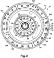
- the first oscillator P1 pendular carried by the washer 24A comprises an even number of pendulum masses, here a total of four masses M1, M3, M5 and M7 distributed circumferentially in a regular manner, as illustrated by the figures 1 , 2 and 4 .
- said at least one pendular mass M n of the first pendulum oscillator P1 comprises at least two flyweights 70A and 70B which are arranged axially on either side of the washer 24A associated.
- Each of the four masses M1, M3, M5 and M7 of the first pendulum oscillator P1 comprises at least two weights 70A and 70B which are arranged axially on either side of the washer 24A associated.
- the first pendular oscillator P1 comprises an odd number of masses M n , for example three or five masses, each of said masses advantageously comprising two flyweights 70A and 70B which are arranged axially on either side of the washer 24A associated.
- the second pendular oscillator P2 comprises at least one pair of masses M n + 1 pendulary respectively comprising a pendular mass M2 and a mass M4 pendular.
- the pendulum mass M2 and the pendulum mass M4 are therefore paired.
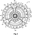
- the pendent masses M2, M4 of the second pendular oscillator P2 are arranged, circumferentially on the associated washer 24B, diametrically opposite to each other.
- the second pendular oscillator P2 carried by the washer 24B comprises an even number of pendulum masses, here a total of four masses M2, M4, M6 and M8 distributed circumferentially in a regular manner, as illustrated by the figures 1 , 3 and 4 .
- said at least one pendular M n + 1 mass of the second pendular oscillator P2 comprises at least two flyweights 72A and 72B which are arranged axially on either side of the associated washer 24B.
- Each of the four masses M2, M4, M6 and M8 of the second pendular oscillator P2 comprises at least two weights 72A and 72B which are arranged axially on either side of the washer 24B associated.
- the second pendular oscillator P2 has an odd number of masses Mn, each of said masses advantageously comprising two flyweights 72A and 72B which are arranged axially on either side of the associated washer 24B.
- first and second input discs 12A, 12B are arranged axially on either side of the output element 14 formed by the web 22.
- the axial spacing between the first input disk 12A and the second input disk 12B is given by the tabs 18 forming the connecting means and determined so as to avoid any contact with the web 22.
- the first and second input discs 12A, 12B are respectively arranged axially between the web 22 and the washer 24A, 24B associated, the first washer 24A being arranged axially in front of the first input disk 12A and the second washer 24B being arranged axially behind the second disk 12B input.
- the outlet hub 56 has, axially at the rear, an outer cylindrical face 74 on which the turbine hub 66 is mounted, the turbine hub 66 being blocked axially forwards by a central part of the outlet hub 56 and axially towards the rear by an elastic ring 76 which is mounted in a groove 78 of the outlet hub 56.
- the outlet hub 56 is axially stepped and comprises, in front of the cylindrical face 74, said central portion to which the web 22 is welded and further forward, a cylindrical face 80.
- the turbine hub 66 comprises, axially successively, from front to rear, a cylindrical face 82 on which is centered the second input disk 12B, a central cylindrical face 84 on which the second washer 12B is centered and one face 86 cylindrical on which is centered the turbine 50.
- the first and second oscillators P1, P2 pendular can be made according to many variants, the example described and shown is accordingly given without limitation.
- the weights 70A and 70B of the first pendular oscillator P1 and the weights 72A and 72B of the second pendular oscillator P2 are respectively arranged at the outer radial periphery of the first washer 24A and the second washer 24B so as to be subjected to a centrifugal force maximum when rotating about the X axis of the damping device 10.
- the first pendular oscillator P1 comprises four pairs of weights 70A, 70B corresponding to the masses M1 to M7 and the second pendular oscillator P2 also comprises four pairs of weights 72A, 72B corresponding to the masses M2 to M8.
- the weights 70A, 70B carried by the first washer 24A and the weights 72A, 72B carried by the second washer 24B are arranged radially on the same diameter, that is to say at the same distance from the axis X of rotation and outside the elastic members 16.
- the weights 70A, 70B of the first pendulum oscillator P1 are offset radially relative to the weights 72A, 72B of the second oscillator P2 pendular.
- the number of flyweights of the first pendular oscillator P1 is different from that of the second pendular oscillator P2, and even when each has the same number of flyweights, the value of the mass and / or the tuning order may differ from a pendulum oscillator to the other.
- each of the pendent weights 70A, 70B and 72A, 72B generally has a wafer shape which extends in a radial plane and which is curved in an arc so that its outer contour matches the outer peripheral edge of the washer 24 associated .
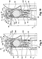
- the weights 70A and 70B of the first oscillator P1 pendulum are mounted oscillating relative to the first washer 24A via associated bearing means 88, as are also the weights 72A and 72B of the second oscillator P2 pendular relative at the second washer 24B.
- the pendulum oscillators P1 and P2 are analogous here, so that the following description made for one also applies to the other.
- the rolling means are constituted by at least one hinge pin 88, each end portion 90 of which is received in an orifice 92 of an associated pendulum weight 70A, 70B, said pin comprising a central portion 94 received sliding in a associated guide slot 96 of the washer 24A.
- each counterweight 70A, 70B pendular is a track in which the associated end portion 90 of the hinge pin 88 is slidably received in a radial plane, orthogonal to the axis X of axial orientation.
- the first oscillator P1 pendulum also comprises at least one fixing pin 98, preferably three pins, each end section of the fixing pin 98 being fixed to one of the weights 70A, 70B pendulum.
- Each free axial end portion of a fixing pin 98 is fixed in an orifice 100 of an associated pendulum weight, the pins 98 are fixed to the flyweights by deformation of their free axial ends in the manner of a rivet so that the two weights 70A and 70B for the first oscillator P1 pendulum (or 72A and 72B) are fixed rigidly to each other.
- the fixing pin 98 forms a spacer which holds the two counterbalanced weights 70A and 70B spaced axially by a determined distance so that the counterbalanced weights 70A, 70B do not come into contact with the washer 24A.
- the first washer 24A comprises for each fixing pin 98 a slot 102 of axially through guide to allow the passage of the central section of each pin 98.
- the figure 11 represents an exemplary embodiment of aforementioned synchronization means implemented when the first pendular oscillator P1 and the second pendular oscillator P2 have the same order of agreement.
- the first pendular oscillator P1 and the second pendular oscillator P2 are advantageously synchronized together by means of synchronization means connecting said at least one pendulum mass M1 of the first pendulum oscillator P1 to said at least one pendular mass M2 of the second pendular oscillator P2.
- the synchronization means are for example made in the form of a piece 104 forming a bridge axially connecting a flyweight 70B of the first oscillator P1 pendulum to a feeder 72A of the second oscillator P2 pendulum.
- the first and second oscillators P1, P2 pendular behave globally as a single pendulum oscillator.
- a damping device 10 comprising at least two pendular oscillators is all the more interesting especially when each pendulum oscillator has a corresponding given order of agreement at one of the ranks of harmonic.
- the rotational connection of the turbine 50 with the damping device 10 can be carried out in different ways, in particular according to whether it is desired or not to add the inertia of the turbine 50 to an element of the damping device 10.
- the turbine 50 is rotatably connected to the second inlet disk 12B and to the second washer 24B.
- the figure 12 represents an alternative embodiment in which at least the second washer 24B carrying the second pendular oscillator P2 is rotatably connected to the turbine 50 of the converter.
- the turbine 50 is no longer linked in rotation to the second input disk 12B, therefore to the input element 12 of the damping device 10.
- first washer 24A and the second washer 24B are rotatably mounted relative to the input elements 12 and 14 output.
- the turbine is rotatably connected to the second washer via attachment means 106, such as rivets.
- the damping device 10 advantageously comprises a turbine hub 66 to which is connected in rotation the turbine 50 of a converter, said turbine hub 66 being connected in rotation directly to a driven shaft or via the output hub 56 of the damping device 10.
- the turbine hub 66 is rotatably connected to the outlet hub 56 by means of coupling means, said outlet hub 56 being, on the one hand, rotatably connected to the output element 14 of the device 10. damping and, secondly, adapted to drive in rotation a driven shaft, in particular by meshing.
- the figure 13 represents another variant in which the output element 14 of the damping device 10 is rotatably connected to the turbine 50, directly or via the turbine hub 66.
- the turbine 50 is rotatably connected to the turbine hub 66 by fastening means 108, such as rivets, and the turbine hub 66 is rotatably connected and rotatably connected by means 110. coupling directly to the driven shaft or via an outlet hub 56 of the damping device 10.
- the means 110 for coupling between the turbine hub 66 and the outlet hub 56 of the damping device 10 are formed by cooperation of shapes, in particular by means of complementary splines which respectively comprise the turbine hub 66 and the outlet hub 56.
- the means 110 for coupling between the hub 66 of the turbine and the hub 56 of the output device 10 damping are constituted by keys (not shown).
- the coupling means 110 between the turbine hub 66 and the outlet hub 56 of the damping device 10 may be made according to other variants, for example and in a non-limiting manner by a force fitting (tightening). ), by welding or by a type of "bikini" assembly, that is to say a crimping and axial stop.
Landscapes
- Engineering & Computer Science (AREA)
- General Engineering & Computer Science (AREA)
- Physics & Mathematics (AREA)
- Acoustics & Sound (AREA)
- Aviation & Aerospace Engineering (AREA)
- Mechanical Engineering (AREA)
- Mechanical Operated Clutches (AREA)
- Vibration Prevention Devices (AREA)
Applications Claiming Priority (2)
| Application Number | Priority Date | Filing Date | Title |
|---|---|---|---|
| FR1154966A FR2976331B1 (fr) | 2011-06-07 | 2011-06-07 | Dispositif d'amortissement de torsion, notamment pour une transmission de vehicule automobile |
| PCT/FR2012/050917 WO2012168604A1 (fr) | 2011-06-07 | 2012-04-25 | Dispositif d'amortissement de torsion, notamment pour une transmission de vehicule automobile |
Publications (2)
| Publication Number | Publication Date |
|---|---|
| EP2718588A1 EP2718588A1 (fr) | 2014-04-16 |
| EP2718588B1 true EP2718588B1 (fr) | 2016-03-30 |
Family
ID=46201678
Family Applications (1)
| Application Number | Title | Priority Date | Filing Date |
|---|---|---|---|
| EP12725052.0A Not-in-force EP2718588B1 (fr) | 2011-06-07 | 2012-04-25 | Dispositif d'amortissement de torsion, notamment pour une transmission de vehicule automobile |
Country Status (7)
Families Citing this family (22)
| Publication number | Priority date | Publication date | Assignee | Title |
|---|---|---|---|---|
| EP2954224B1 (fr) * | 2013-02-11 | 2019-05-01 | Valeo Embrayages | Dispositif de transmission de couple pour un véhicule automobile |
| CN105209781B (zh) * | 2013-04-02 | 2017-09-29 | 舍弗勒技术股份两合公司 | 用于车辆的阻尼器装置以及用于构造阻尼器装置的方法 |
| FR3009049B1 (fr) * | 2013-07-29 | 2016-01-22 | Valeo Embrayages | Disque d'embrayage pour embrayage a friction |
| DE102014214523A1 (de) | 2013-07-30 | 2015-02-05 | Schaeffler Technologies Gmbh & Co. Kg | Fliehkraftpendel und Antriebssystem mit Fliehkraftpendel |
| DE102013219504A1 (de) | 2013-09-27 | 2015-04-16 | Zf Friedrichshafen Ag | Torsionsschwingungsdämpfer |
| DE102013219503A1 (de) | 2013-09-27 | 2015-04-23 | Zf Friedrichshafen Ag | Torsionsschwingungsdämpfer |
| DE102013219505A1 (de) * | 2013-09-27 | 2015-04-16 | Zf Friedrichshafen Ag | Tilgersystem |
| DE102013219500B4 (de) | 2013-09-27 | 2024-10-17 | Zf Friedrichshafen Ag | Torsionsschwingungsdämpfer |
| DE112014006283A5 (de) * | 2014-01-28 | 2016-10-20 | Schaeffler Technologies AG & Co. KG | Fliehkraftpendel |
| CN106133388B (zh) * | 2014-04-02 | 2018-04-03 | 舍弗勒技术股份两合公司 | 离心力摆装置和旋转振动减振器 |
| WO2015176725A1 (de) * | 2014-05-21 | 2015-11-26 | Schaeffler Technologies AG & Co. KG | Antriebssystem |
| US10415667B2 (en) | 2014-07-24 | 2019-09-17 | Schaeffler Technologies AG & Co. KG | Damper system |
| EP3172461B1 (de) * | 2014-07-24 | 2019-03-13 | Schaeffler Technologies AG & Co. KG | Drehmomentübertragungseinrichtung sowie getriebe |
| DE102014224430A1 (de) * | 2014-11-28 | 2016-06-02 | Schaeffler Technologies AG & Co. KG | Schwingungstilgungseinrichtung |
| FR3038026B1 (fr) | 2015-06-24 | 2019-09-13 | Valeo Embrayages | Composant d'inertie additionnelle pour chaine de propulsion de vehicule |
| FR3039235B1 (fr) * | 2015-07-24 | 2019-04-12 | Valeo Embrayages | Dispositif d’amortissement de vibration |
| FR3039237B1 (fr) * | 2015-07-24 | 2018-03-02 | Valeo Embrayages | Dispositif de transmission de couple pour un vehicule automobile |
| DE102015215897A1 (de) | 2015-08-20 | 2017-02-23 | Schaeffler Technologies AG & Co. KG | Kupplungseinrichtung für Hybridantrieb |
| WO2017067553A1 (de) * | 2015-10-21 | 2017-04-27 | Schaeffler Technologies AG & Co. KG | Drehschwingungsdämpferaggregat |
| US10393247B2 (en) * | 2016-05-23 | 2019-08-27 | Valeo Embrayages | Hydrokinetic torque coupling device with torsional vibration damper in combination with two vibration absorbers |
| FR3104658B1 (fr) * | 2019-12-17 | 2021-12-17 | Valeo Embrayages | Dispositif d'amortissement pendulaire et Procédé de fabrication d’un tel dispositif |
| DE102020107699A1 (de) | 2020-03-20 | 2021-09-23 | Schaeffler Technologies AG & Co. KG | Drehmomentübertragungseinrichtung |
Family Cites Families (7)
| Publication number | Priority date | Publication date | Assignee | Title |
|---|---|---|---|---|
| US2632318A (en) * | 1946-11-26 | 1953-03-24 | Schweizerische Lokomotiv | Universally movable coupling having a floating intermediate ring |
| DE2917448A1 (de) * | 1979-04-30 | 1980-11-13 | Luk Lamellen & Kupplungsbau | Fliehkraftreibungskupplung |
| JPH0758107B2 (ja) * | 1985-11-15 | 1995-06-21 | 株式会社大金製作所 | ダンパーディスクのスプリング支持構造 |
| DE112008003167B4 (de) * | 2007-11-29 | 2016-07-21 | Schaeffler Technologies AG & Co. KG | Kraftübertragungsvorrichtung mit einem drehzahladaptiven Tilger und Verfahren zur Verbesserung des Dämpfungsverhaltens |
| USRE48872E1 (en) * | 2008-07-04 | 2022-01-04 | Schaeffler Technologies AG & Co. KG | Hydrodynamic torque converter |
| DE202010018604U1 (de) * | 2009-04-27 | 2018-04-27 | Schaeffler Technologies AG & Co. KG | Hydrodynamischer Drehmomentwandler |
| DE112011100546B4 (de) * | 2010-02-16 | 2019-12-12 | Schaeffler Technologies AG & Co. KG | Hydrodynamischer Drehmomentwandler |
-
2011
- 2011-06-07 FR FR1154966A patent/FR2976331B1/fr not_active Expired - Fee Related
-
2012
- 2012-04-25 JP JP2014514127A patent/JP6001058B2/ja not_active Expired - Fee Related
- 2012-04-25 HU HUE12725052A patent/HUE028788T2/en unknown
- 2012-04-25 WO PCT/FR2012/050917 patent/WO2012168604A1/fr active Application Filing
- 2012-04-25 EP EP12725052.0A patent/EP2718588B1/fr not_active Not-in-force
- 2012-04-25 US US14/124,193 patent/US9068624B2/en not_active Expired - Fee Related
- 2012-04-25 KR KR1020137032221A patent/KR101967491B1/ko not_active Expired - Fee Related
Also Published As
| Publication number | Publication date |
|---|---|
| US9068624B2 (en) | 2015-06-30 |
| FR2976331A1 (fr) | 2012-12-14 |
| HUE028788T2 (en) | 2017-01-30 |
| JP6001058B2 (ja) | 2016-10-05 |
| US20140113733A1 (en) | 2014-04-24 |
| EP2718588A1 (fr) | 2014-04-16 |
| KR101967491B1 (ko) | 2019-04-09 |
| JP2014516145A (ja) | 2014-07-07 |
| KR20140030236A (ko) | 2014-03-11 |
| WO2012168604A1 (fr) | 2012-12-13 |
| FR2976331B1 (fr) | 2013-05-24 |
Similar Documents
| Publication | Publication Date | Title |
|---|---|---|
| EP2718588B1 (fr) | Dispositif d'amortissement de torsion, notamment pour une transmission de vehicule automobile | |
| EP2721317B1 (fr) | Dispositif d'amortissement de torsion comportant des masselottes pendulaires decalees axialement par rapport a des rondelles de guidage | |
| EP2769118B1 (fr) | Systeme d'amortissement de type oscillateur pendulaire comportant un dispositif de guidage perfectionne | |
| EP2839181B1 (fr) | Dispositif d'amortissement pendulaire, en particulier pour une transmission de véhicule automobile | |
| EP2705273B1 (fr) | Dispositif d'amortissement de torsion comportant des masselottes pendulaires montées sur une rondelle de phasage | |
| EP2705275B1 (fr) | Dispositif d'amortissement de torsion a masselottes pendulaires a basculement limite | |
| EP2776736B1 (fr) | Dispositif de filtration de type oscillateur pendulaire comportant un systeme de guidage perfectionne | |
| FR3023599A1 (fr) | Amortisseur pour dispositif de transmission de couple de vehicule automobile | |
| FR2959547A1 (fr) | Poulie de decouplage. | |
| WO2013121137A1 (fr) | Dispositif amortisseur de torsion comportant deux voiles de sortie de couple qui sont agences de part et d'autre de rondelles d'entrée de couple | |
| FR3034481B1 (fr) | Dispositif de transmission de couple pour un vehicule automobile | |
| FR2986296A1 (fr) | Dispositif de transmission de couple pour vehicule automobile | |
| WO2015162386A1 (fr) | Dispositif de transmission de couple pour un véhicule automobile | |
| WO2005026575A1 (fr) | Embrayage a friction, en particulier pour un vehicule automobile, comportant des moyens multifonction | |
| EP2098756B1 (fr) | Dispositif d'amortissement comportant un système d'amortissement des vibrations formé par un batteur inertiel | |
| FR3051869A1 (fr) | Dispositif de transmission de couple, notamment pour vehicule automobile | |
| EP2705274B1 (fr) | Dispositif d'amortissement de torsion comportant des organes élastiques dont chacun est maintenu individuellement en position par une rondelle de phasage | |
| FR3034155A1 (fr) | Dispositif d'amortissement d'oscillations de torsion | |
| FR3034483B1 (fr) | Dispositif de transmission de couple pour un vehicule automobile | |
| EP3073146B1 (fr) | Composant pour systeme de transmission, notamment disque d'embrayage | |
| EP3882480A1 (fr) | Ensemble de transmission de couple, en particulier pour vehicule automobile | |
| FR3012858A1 (fr) | Dispositif de filtration de type oscillateur pendulaire et masselotte pour un tel dispositif de filtration | |
| FR3059382A1 (fr) | Dispositif d'amortissement pendulaire | |
| FR3036761A1 (fr) | Dispositif d'amortissement d'oscillations de torsion | |
| FR3046645A1 (fr) | Ensemble pour convertisseur hydrodynamique de couple |
Legal Events
| Date | Code | Title | Description |
|---|---|---|---|
| PUAI | Public reference made under article 153(3) epc to a published international application that has entered the european phase |
Free format text: ORIGINAL CODE: 0009012 |
|
| 17P | Request for examination filed |
Effective date: 20131125 |
|
| AK | Designated contracting states |
Kind code of ref document: A1 Designated state(s): AL AT BE BG CH CY CZ DE DK EE ES FI FR GB GR HR HU IE IS IT LI LT LU LV MC MK MT NL NO PL PT RO RS SE SI SK SM TR |
|
| DAX | Request for extension of the european patent (deleted) | ||
| 17Q | First examination report despatched |
Effective date: 20150220 |
|
| REG | Reference to a national code |
Ref country code: DE Ref legal event code: R079 Ref document number: 602012016279 Country of ref document: DE Free format text: PREVIOUS MAIN CLASS: F16F0015140000 Ipc: F16F0015120000 |
|
| GRAP | Despatch of communication of intention to grant a patent |
Free format text: ORIGINAL CODE: EPIDOSNIGR1 |
|
| INTG | Intention to grant announced |
Effective date: 20151029 |
|
| RIC1 | Information provided on ipc code assigned before grant |
Ipc: F16F 15/12 20060101AFI20151016BHEP Ipc: F16F 15/14 20060101ALI20151016BHEP |
|
| GRAS | Grant fee paid |
Free format text: ORIGINAL CODE: EPIDOSNIGR3 |
|
| GRAA | (expected) grant |
Free format text: ORIGINAL CODE: 0009210 |
|
| AK | Designated contracting states |
Kind code of ref document: B1 Designated state(s): AL AT BE BG CH CY CZ DE DK EE ES FI FR GB GR HR HU IE IS IT LI LT LU LV MC MK MT NL NO PL PT RO RS SE SI SK SM TR |
|
| REG | Reference to a national code |
Ref country code: GB Ref legal event code: FG4D Free format text: NOT ENGLISH |
|
| REG | Reference to a national code |
Ref country code: CH Ref legal event code: EP |
|
| REG | Reference to a national code |
Ref country code: AT Ref legal event code: REF Ref document number: 785754 Country of ref document: AT Kind code of ref document: T Effective date: 20160415 |
|
| REG | Reference to a national code |
Ref country code: IE Ref legal event code: FG4D Free format text: LANGUAGE OF EP DOCUMENT: FRENCH |
|
| REG | Reference to a national code |
Ref country code: FR Ref legal event code: PLFP Year of fee payment: 5 |
|
| REG | Reference to a national code |
Ref country code: DE Ref legal event code: R096 Ref document number: 602012016279 Country of ref document: DE |
|
| REG | Reference to a national code |
Ref country code: LT Ref legal event code: MG4D |
|
| PG25 | Lapsed in a contracting state [announced via postgrant information from national office to epo] |
Ref country code: GR Free format text: LAPSE BECAUSE OF FAILURE TO SUBMIT A TRANSLATION OF THE DESCRIPTION OR TO PAY THE FEE WITHIN THE PRESCRIBED TIME-LIMIT Effective date: 20160701 Ref country code: NO Free format text: LAPSE BECAUSE OF FAILURE TO SUBMIT A TRANSLATION OF THE DESCRIPTION OR TO PAY THE FEE WITHIN THE PRESCRIBED TIME-LIMIT Effective date: 20160630 Ref country code: HR Free format text: LAPSE BECAUSE OF FAILURE TO SUBMIT A TRANSLATION OF THE DESCRIPTION OR TO PAY THE FEE WITHIN THE PRESCRIBED TIME-LIMIT Effective date: 20160330 Ref country code: FI Free format text: LAPSE BECAUSE OF FAILURE TO SUBMIT A TRANSLATION OF THE DESCRIPTION OR TO PAY THE FEE WITHIN THE PRESCRIBED TIME-LIMIT Effective date: 20160330 |
|
| REG | Reference to a national code |
Ref country code: NL Ref legal event code: MP Effective date: 20160330 |
|
| REG | Reference to a national code |
Ref country code: AT Ref legal event code: MK05 Ref document number: 785754 Country of ref document: AT Kind code of ref document: T Effective date: 20160330 |
|
| PG25 | Lapsed in a contracting state [announced via postgrant information from national office to epo] |
Ref country code: LT Free format text: LAPSE BECAUSE OF FAILURE TO SUBMIT A TRANSLATION OF THE DESCRIPTION OR TO PAY THE FEE WITHIN THE PRESCRIBED TIME-LIMIT Effective date: 20160330 Ref country code: SE Free format text: LAPSE BECAUSE OF FAILURE TO SUBMIT A TRANSLATION OF THE DESCRIPTION OR TO PAY THE FEE WITHIN THE PRESCRIBED TIME-LIMIT Effective date: 20160330 Ref country code: LV Free format text: LAPSE BECAUSE OF FAILURE TO SUBMIT A TRANSLATION OF THE DESCRIPTION OR TO PAY THE FEE WITHIN THE PRESCRIBED TIME-LIMIT Effective date: 20160330 Ref country code: RS Free format text: LAPSE BECAUSE OF FAILURE TO SUBMIT A TRANSLATION OF THE DESCRIPTION OR TO PAY THE FEE WITHIN THE PRESCRIBED TIME-LIMIT Effective date: 20160330 Ref country code: BE Free format text: LAPSE BECAUSE OF NON-PAYMENT OF DUE FEES Effective date: 20160430 |
|
| PG25 | Lapsed in a contracting state [announced via postgrant information from national office to epo] |
Ref country code: NL Free format text: LAPSE BECAUSE OF FAILURE TO SUBMIT A TRANSLATION OF THE DESCRIPTION OR TO PAY THE FEE WITHIN THE PRESCRIBED TIME-LIMIT Effective date: 20160330 |
|
| PG25 | Lapsed in a contracting state [announced via postgrant information from national office to epo] |
Ref country code: IS Free format text: LAPSE BECAUSE OF FAILURE TO SUBMIT A TRANSLATION OF THE DESCRIPTION OR TO PAY THE FEE WITHIN THE PRESCRIBED TIME-LIMIT Effective date: 20160730 Ref country code: EE Free format text: LAPSE BECAUSE OF FAILURE TO SUBMIT A TRANSLATION OF THE DESCRIPTION OR TO PAY THE FEE WITHIN THE PRESCRIBED TIME-LIMIT Effective date: 20160330 Ref country code: PL Free format text: LAPSE BECAUSE OF FAILURE TO SUBMIT A TRANSLATION OF THE DESCRIPTION OR TO PAY THE FEE WITHIN THE PRESCRIBED TIME-LIMIT Effective date: 20160330 |
|
| PG25 | Lapsed in a contracting state [announced via postgrant information from national office to epo] |
Ref country code: CZ Free format text: LAPSE BECAUSE OF FAILURE TO SUBMIT A TRANSLATION OF THE DESCRIPTION OR TO PAY THE FEE WITHIN THE PRESCRIBED TIME-LIMIT Effective date: 20160330 Ref country code: ES Free format text: LAPSE BECAUSE OF FAILURE TO SUBMIT A TRANSLATION OF THE DESCRIPTION OR TO PAY THE FEE WITHIN THE PRESCRIBED TIME-LIMIT Effective date: 20160330 Ref country code: SK Free format text: LAPSE BECAUSE OF FAILURE TO SUBMIT A TRANSLATION OF THE DESCRIPTION OR TO PAY THE FEE WITHIN THE PRESCRIBED TIME-LIMIT Effective date: 20160330 Ref country code: SM Free format text: LAPSE BECAUSE OF FAILURE TO SUBMIT A TRANSLATION OF THE DESCRIPTION OR TO PAY THE FEE WITHIN THE PRESCRIBED TIME-LIMIT Effective date: 20160330 Ref country code: RO Free format text: LAPSE BECAUSE OF FAILURE TO SUBMIT A TRANSLATION OF THE DESCRIPTION OR TO PAY THE FEE WITHIN THE PRESCRIBED TIME-LIMIT Effective date: 20160330 Ref country code: PT Free format text: LAPSE BECAUSE OF FAILURE TO SUBMIT A TRANSLATION OF THE DESCRIPTION OR TO PAY THE FEE WITHIN THE PRESCRIBED TIME-LIMIT Effective date: 20160801 Ref country code: AT Free format text: LAPSE BECAUSE OF FAILURE TO SUBMIT A TRANSLATION OF THE DESCRIPTION OR TO PAY THE FEE WITHIN THE PRESCRIBED TIME-LIMIT Effective date: 20160330 |
|
| REG | Reference to a national code |
Ref country code: CH Ref legal event code: PL |
|
| PG25 | Lapsed in a contracting state [announced via postgrant information from national office to epo] |
Ref country code: IT Free format text: LAPSE BECAUSE OF FAILURE TO SUBMIT A TRANSLATION OF THE DESCRIPTION OR TO PAY THE FEE WITHIN THE PRESCRIBED TIME-LIMIT Effective date: 20160330 |
|
| REG | Reference to a national code |
Ref country code: DE Ref legal event code: R097 Ref document number: 602012016279 Country of ref document: DE |
|
| REG | Reference to a national code |
Ref country code: IE Ref legal event code: MM4A |
|
| REG | Reference to a national code |
Ref country code: HU Ref legal event code: AG4A Ref document number: E028788 Country of ref document: HU |
|
| PG25 | Lapsed in a contracting state [announced via postgrant information from national office to epo] |
Ref country code: DK Free format text: LAPSE BECAUSE OF FAILURE TO SUBMIT A TRANSLATION OF THE DESCRIPTION OR TO PAY THE FEE WITHIN THE PRESCRIBED TIME-LIMIT Effective date: 20160330 Ref country code: LI Free format text: LAPSE BECAUSE OF NON-PAYMENT OF DUE FEES Effective date: 20160430 Ref country code: CH Free format text: LAPSE BECAUSE OF NON-PAYMENT OF DUE FEES Effective date: 20160430 |
|
| PLBE | No opposition filed within time limit |
Free format text: ORIGINAL CODE: 0009261 |
|
| STAA | Information on the status of an ep patent application or granted ep patent |
Free format text: STATUS: NO OPPOSITION FILED WITHIN TIME LIMIT |
|
| GBPC | Gb: european patent ceased through non-payment of renewal fee |
Effective date: 20160630 |
|
| 26N | No opposition filed |
Effective date: 20170103 |
|
| REG | Reference to a national code |
Ref country code: FR Ref legal event code: PLFP Year of fee payment: 6 |
|
| PG25 | Lapsed in a contracting state [announced via postgrant information from national office to epo] |
Ref country code: IE Free format text: LAPSE BECAUSE OF NON-PAYMENT OF DUE FEES Effective date: 20160425 Ref country code: SI Free format text: LAPSE BECAUSE OF FAILURE TO SUBMIT A TRANSLATION OF THE DESCRIPTION OR TO PAY THE FEE WITHIN THE PRESCRIBED TIME-LIMIT Effective date: 20160330 Ref country code: GB Free format text: LAPSE BECAUSE OF NON-PAYMENT OF DUE FEES Effective date: 20160630 |
|
| REG | Reference to a national code |
Ref country code: FR Ref legal event code: PLFP Year of fee payment: 7 |
|
| PG25 | Lapsed in a contracting state [announced via postgrant information from national office to epo] |
Ref country code: CY Free format text: LAPSE BECAUSE OF FAILURE TO SUBMIT A TRANSLATION OF THE DESCRIPTION OR TO PAY THE FEE WITHIN THE PRESCRIBED TIME-LIMIT Effective date: 20160330 |
|
| PG25 | Lapsed in a contracting state [announced via postgrant information from national office to epo] |
Ref country code: MK Free format text: LAPSE BECAUSE OF FAILURE TO SUBMIT A TRANSLATION OF THE DESCRIPTION OR TO PAY THE FEE WITHIN THE PRESCRIBED TIME-LIMIT Effective date: 20160330 Ref country code: LU Free format text: LAPSE BECAUSE OF NON-PAYMENT OF DUE FEES Effective date: 20160425 Ref country code: TR Free format text: LAPSE BECAUSE OF FAILURE TO SUBMIT A TRANSLATION OF THE DESCRIPTION OR TO PAY THE FEE WITHIN THE PRESCRIBED TIME-LIMIT Effective date: 20160330 Ref country code: MC Free format text: LAPSE BECAUSE OF FAILURE TO SUBMIT A TRANSLATION OF THE DESCRIPTION OR TO PAY THE FEE WITHIN THE PRESCRIBED TIME-LIMIT Effective date: 20160330 Ref country code: MT Free format text: LAPSE BECAUSE OF FAILURE TO SUBMIT A TRANSLATION OF THE DESCRIPTION OR TO PAY THE FEE WITHIN THE PRESCRIBED TIME-LIMIT Effective date: 20160330 |
|
| PG25 | Lapsed in a contracting state [announced via postgrant information from national office to epo] |
Ref country code: BG Free format text: LAPSE BECAUSE OF FAILURE TO SUBMIT A TRANSLATION OF THE DESCRIPTION OR TO PAY THE FEE WITHIN THE PRESCRIBED TIME-LIMIT Effective date: 20160330 |
|
| PG25 | Lapsed in a contracting state [announced via postgrant information from national office to epo] |
Ref country code: AL Free format text: LAPSE BECAUSE OF FAILURE TO SUBMIT A TRANSLATION OF THE DESCRIPTION OR TO PAY THE FEE WITHIN THE PRESCRIBED TIME-LIMIT Effective date: 20160330 |
|
| PGFP | Annual fee paid to national office [announced via postgrant information from national office to epo] |
Ref country code: FR Payment date: 20190429 Year of fee payment: 8 Ref country code: HU Payment date: 20190320 Year of fee payment: 8 |
|
| PG25 | Lapsed in a contracting state [announced via postgrant information from national office to epo] |
Ref country code: FR Free format text: LAPSE BECAUSE OF NON-PAYMENT OF DUE FEES Effective date: 20200430 Ref country code: HU Free format text: LAPSE BECAUSE OF NON-PAYMENT OF DUE FEES Effective date: 20200426 |
|
| P01 | Opt-out of the competence of the unified patent court (upc) registered |
Effective date: 20230528 |
|
| PGFP | Annual fee paid to national office [announced via postgrant information from national office to epo] |
Ref country code: DE Payment date: 20230412 Year of fee payment: 12 |
|
| REG | Reference to a national code |
Ref country code: DE Ref legal event code: R119 Ref document number: 602012016279 Country of ref document: DE |
|
| PG25 | Lapsed in a contracting state [announced via postgrant information from national office to epo] |
Ref country code: DE Free format text: LAPSE BECAUSE OF NON-PAYMENT OF DUE FEES Effective date: 20241105 |
|
| PG25 | Lapsed in a contracting state [announced via postgrant information from national office to epo] |
Ref country code: DE Free format text: LAPSE BECAUSE OF NON-PAYMENT OF DUE FEES Effective date: 20241105 |