EP2718052B1 - System und verfahren zur erzeugung einer schweissung am beginn eines schweissprozesses durch begrenzung der ausgangsleistung - Google Patents
System und verfahren zur erzeugung einer schweissung am beginn eines schweissprozesses durch begrenzung der ausgangsleistung Download PDFInfo
- Publication number
- EP2718052B1 EP2718052B1 EP12726970.2A EP12726970A EP2718052B1 EP 2718052 B1 EP2718052 B1 EP 2718052B1 EP 12726970 A EP12726970 A EP 12726970A EP 2718052 B1 EP2718052 B1 EP 2718052B1
- Authority
- EP
- European Patent Office
- Prior art keywords
- welding
- control circuit
- energy output
- power
- output
- Prior art date
- Legal status (The legal status is an assumption and is not a legal conclusion. Google has not performed a legal analysis and makes no representation as to the accuracy of the status listed.)
- Active
Links
Images


Classifications
-
- B—PERFORMING OPERATIONS; TRANSPORTING
- B23—MACHINE TOOLS; METAL-WORKING NOT OTHERWISE PROVIDED FOR
- B23K—SOLDERING OR UNSOLDERING; WELDING; CLADDING OR PLATING BY SOLDERING OR WELDING; CUTTING BY APPLYING HEAT LOCALLY, e.g. FLAME CUTTING; WORKING BY LASER BEAM
- B23K9/00—Arc welding or cutting
- B23K9/06—Arrangements or circuits for starting the arc, e.g. by generating ignition voltage, or for stabilising the arc
- B23K9/067—Starting the arc
- B23K9/0672—Starting the arc without direct contact between electrodes
- B23K9/0673—Ionisation of the arc gap by means of pulsed or high-frequency voltages
-
- B—PERFORMING OPERATIONS; TRANSPORTING
- B23—MACHINE TOOLS; METAL-WORKING NOT OTHERWISE PROVIDED FOR
- B23K—SOLDERING OR UNSOLDERING; WELDING; CLADDING OR PLATING BY SOLDERING OR WELDING; CUTTING BY APPLYING HEAT LOCALLY, e.g. FLAME CUTTING; WORKING BY LASER BEAM
- B23K9/00—Arc welding or cutting
- B23K9/06—Arrangements or circuits for starting the arc, e.g. by generating ignition voltage, or for stabilising the arc
- B23K9/073—Stabilising the arc
-
- B—PERFORMING OPERATIONS; TRANSPORTING
- B23—MACHINE TOOLS; METAL-WORKING NOT OTHERWISE PROVIDED FOR
- B23K—SOLDERING OR UNSOLDERING; WELDING; CLADDING OR PLATING BY SOLDERING OR WELDING; CUTTING BY APPLYING HEAT LOCALLY, e.g. FLAME CUTTING; WORKING BY LASER BEAM
- B23K9/00—Arc welding or cutting
- B23K9/09—Arrangements or circuits for arc welding with pulsed current or voltage
-
- B—PERFORMING OPERATIONS; TRANSPORTING
- B23—MACHINE TOOLS; METAL-WORKING NOT OTHERWISE PROVIDED FOR
- B23K—SOLDERING OR UNSOLDERING; WELDING; CLADDING OR PLATING BY SOLDERING OR WELDING; CUTTING BY APPLYING HEAT LOCALLY, e.g. FLAME CUTTING; WORKING BY LASER BEAM
- B23K9/00—Arc welding or cutting
- B23K9/10—Other electric circuits therefor; Protective circuits; Remote controls
Definitions
- the present application generally relates to improving arc characteristics of a welder, and, in particular to a system for and a method of generating a weld during a start of a welding process according to the preamble of claims 1 and 12 (see, for example, US 4 403 135 A ).
- Welding systems can experience erratic operation during the start of the welding process due to temperatures of the weldment and filler wire not having yet stabilized. Additionally, welding systems can exhibit repeated stubbing, which manifests as a series of violent contacts of an electrode and work piece. The stubbing can be audible and may be telegraphed through the Metal Inert Gas (MIG) welding gun to the user's hand. The stubbing prolongs and impedes initiation of the weld, making optimal steady-state settings difficult to establish. Welding systems encountering these problems may not provide for optimal welds.
- MIG Metal Inert Gas
- the present disclosure discusses optimizing starting characteristics by providing, at the start of the welding process, a controlled current pulse that is based on output voltage and run in settings, for example. Additionally, the present disclosure discusses optimizing starting characteristics and preventing stubbing by optimizing at the start of the welding process, output voltage, wire feed, and inductance, for example.
- a system for providing an improved start in a welding process according to claim 1 is provided.
- a power circuit generates welding output power for a welding process.
- a control circuit is in communication with the power circuit to control the start of the welding process.
- the control circuit is in communication with the power circuit to control, during the start of the welding process, at least one welding parameter until the control circuit determines that welding energy output exceeds an energy output threshold.
- a method of generating a weld during a start of a welding process includes generating, by a power circuit, welding output power.
- the method includes continuously determining, by a control circuit in communication with the power circuit, a welding energy output or a time that the welding output power is provided.
- the method includes controlling, by the control circuit during the start of the welding process, a welding parameter until the welding energy output exceeds an energy output threshold or until the time exceeds a time threshold.
- substantially used herein with reference to a quantity or mathematical relationship includes (1) a variation in the recited quantity or relationship of an amount that is insubstantially different from a recited quantity or relationship for an intended purpose or function, or (2) a variation in the recited quantity or relationship of an amount that produces the same quality.
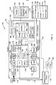
- the power supply 110 receives input power 112 which may be an alternating current power line, for example a 220 volt AC power line. However, it is understood that the power supply 110 may be adaptable to receive a range of voltages, for example between 187 to 276 volts AC. In addition, it may also be possible to configure the power supply for other voltage ranges depending on the application and required welding output power.
- the power supply 110 provides a direct current power output voltage 114 that may be used as a welding output power 116.
- the power supply 110 may be used for stick welding (also known as Shielded Metal Arc Welding or SMAW) or various other welding applications such as MIG (Metal Inert Gas, also known as gas metal arc welding or GMAW), flux core arc welding, TIG (tungsten inert gas welding, also known as Gas Tungsten Arc Welding or GTAW), plasma arc, or other welding processes. Therefore, in one example the current return lead of the welding output power 116 may be provided to a part 118 that is to be welded, and the supply voltage may be provided to an electrode, for example a stick 120 or wire 122.
- stick welding also known as Shielded Metal Arc Welding or SMAW
- MIG Metal Inert Gas
- GMAW gas metal arc welding
- GTAW Gas Tungsten Arc Welding
- plasma arc or other welding processes. Therefore, in one example the current return lead of the welding output power 116 may be provided to a part 118 that is to be welded,
- the output voltage may be provided through a wire 122 which may be continuously fed to the part to form a continuous weld.
- TIG mode the electrode is not melted, and generally only the base metal is melted.
- the power supply 110 may control the output voltage and the output current, as well as the feeding of the wire to optimize the welding process.
- the power supply 110 may be connected to one group of accessories 124 including for example a remote wire feeder 126, a spool gun 128, or a push/pull gun 130.
- the power supply 110 may be connected to other groups of accessories 132, for example through an 8-pin connector.
- the second group of accessories 132 may include a MIG gun 134, a smart gun 136, a foot pedal 138, a pendant 140, a TIG gun 142, and/or a remote control/trigger 144.
- the input power 112 may be provided to a circuit breaker or switch 154. Power may be provided from the circuit breaker 154 to a power circuit 150.
- the power circuit 150 may condition the input power to provide a welding output power 116, as well as, for powering various additional accessories to support the welding process.
- the power circuit 150 may also be in communication with the control circuit 152.
- the control circuit 152 may allow the user to control various welding parameters, as well as, providing various control signals to the power circuit 150 to control various aspects of the welding process.
- the power from the circuit breaker 154 may be provided to an EMI filter 156 of the power circuit 150. Power is provided from the EMI filter 156 to an input bridge 158. Power may be provided from the input bridge 158 to a conditioning circuit 162.
- the conditioning circuit 162 may include a boost circuit, a transformer, as well as a power factor correction circuit. Power is provided from the conditioning circuit 162 to the inverter 160 where the power is converted to a DC signal 114 thereby providing welding output power 116. Power may also be provided to a bias circuit 170 to power a number of accessories internal or external to the power supply 110 that facilitate operation of the power supply and welding process. For example, the bias circuit 170 may provide power to gas solenoid valves 172, fans 174, as well as, other accessory devices. In addition, power is provided to a motor drive circuit 164 that is in communication with a motor 166.
- the motor 166 may be in communication with a feed mechanism 168 configured to feed wire 122 to a weld gun for use in creation of the weld.
- the control circuit 152 may provide control signals to any of the previously mentioned circuits in the power circuit 150 to optimize the weld process and performance of the power supply 110.
- the control circuit 152 may include a pulse width modulator 182 and a processor 184 for analyzing various weld characteristics and calculating various weld parameters according to user settings, as well as, various feedback signals.
- an interface circuit 186 may be provided to control a display 188 that may provide information to the user of the welding system.
- the display 188 may include an LED display, a LCD display, or various other known display technology.
- the display may provide various menu choices to the user, as well as, providing various feedback on the welding process including the values of various parameters or graphs of previous welding characteristics.
- the controls 190 may also be in communication with the interface circuit 186 to allow the user to provide input such as various welding parameters to control the operation of the welding process.
- the power supply 110 may further include a voltage reducing device (VRD) circuit 192, a low-power circuit that detects contact between the part 118 to be welded and the electrode.
- VRD voltage reducing device
- the VRD circuit 192 may reduce the maximum open circuit voltage to safe levels.
- the VRD circuit 192 may no longer reduce the voltage and thus may allow the welding system 100 to operate at full power.
- the VRD circuit 192 may be in communication with a timer 194.
- the timer 194 may be implemented as software as part of the control circuit 152, or may be comprised of an electronic circuit.
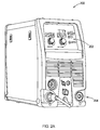
- a housing 200 is provided that may be implemented with the welding system 100.
- the housing 200 may contain the power supply 110, and may further include a user interface 202 and a front connection panel 204.
- the front connection panel 204 may, for example, be used for connecting the power supply 110 to the first and second groups of accessories 124 and 132, as discussed above.
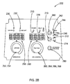
- a particular implementation of a user interface 202 may include various inputs selectable by a user and various indicators and displays.
- a power indicator 210 may indicate when the power supply 110 is receiving the input power 112.
- a fault light 220 may indicate when the welding process has entered a fault condition.
- a VRD "on" indicator 230 may indicate when the VRD is on, and a VRD “off' indicator 232 may indicate when the VRD is off.
- a mode selection input 240 may allow the user to select a desired welding process.
- the mode selection input 240 may be a button which when pressed causes the power supply 100 to cycle through and select a welding process.
- Three welding process indicators 242, 244, 246 may respectively light upon selection of, for example, MIG, TIG, or stick welding.
- the MIG selection provides a suitable configuration for both gas metal arc welding and flux core arc welding.
- a trigger interlock input 270 may allow a user to select between 2T and 4T modes for MIG, TIG and stick welds that are activated via an electric switch.
- the 2T mode allows the user to push and hold the switch to activate and release the switch to deactivate.
- the 4T mode allows the user to push and release the switch to activate, then push and release the switch again to deactivate.
- An indicator 272 may light when the 2T mode is selected, and an indicator 274 may light when the 4T mode is selected.
- An amperage input 252 may allow a user to select a desired output current.
- a wire feed speed input 254 may allow a user to select a desired wire feed speed of the wire 122.
- the desired wire feed speed may be a desired steady-state wire feed speed.
- the inputs 252 and 254 may be combined into an adjustable knob. A user may press the adjustment knob to cycle between the inputs 252 and 254, and then turn the adjustment knob to select a desired value of the current or wire feed speed.
- the selected desired value may be displayed on a display 250, which may be a super bright red LED display.
- a voltage input 262 may allow a user to select a desired output voltage of the welding signal.
- An inductance input 264 may allow a user to select a desired inductance which, for example, may optimize weld bead characteristics.
- An arc force input 266 may allow a user to select desired properties of arc force.
- a down slope input 268 may allow a user to select a down slope time, which is a function of the down ramp rate of the output current.
- the inputs 262, 264, 266, and 268 may be combined into an adjustable knob. A user may press the adjustment knob to cycle between the inputs 262, 264, 266, and 268, and then turn the adjustment knob to select a desired value of the voltage, inductance, arc force, or down slope.
- the selected desired value may be displayed on a display 260, which may be a super bright red LED display.
- An advanced features input 280 may allow a user to select menus and toggle through various further inputs, which are displayed on the displays 250 and 260.
- a MIG welding main menu may provide inputs for operation control, pre-flow, spot on/off, spot time, stitch on/off, stitch time, dwell time, run-in percentage, post-flow, burn back time, wire sharp, and/or a setup submenu.
- the setup submenu may provide inputs for wire feed units, amperage calibration, voltage calibration, wire speed calibration, arc hour display, VRD (on, off or triggered), total weld energy (for heat input computation), and/or factory defaults.
- a stick welding main menu may provide inputs for operation control, hot start on/off, hot start time, hot start amperage, and/or a setup submenu.
- the setup submenu may provide inputs for arc hour display, VRD disable, and factory defaults.
- the TIG main menu may provide inputs for operation control, pre-flow, post-flow, and a setup submenu.
- the setup submenu may provide inputs for arc hour display, VRD disable, and factory defaults.
- Burn back time may refer to an adjustable period of time that the power supply 110 may provide power for the welding process after the wire feed stops in order to burn back the wire and prevent it from sticking in the weld puddle.
- Wire sharp refers to the application of predefined current outputs applied to the wire, for example, a rapid series of powerful current pulses after the motor 166 is de-energized. This prevents a ball of molten metal from freezing on the end of the welding wire, and tapers the end of the weld wire to a sharp point, promoting a cleaner start when welding resumes.
- the current outputs terminate when an open-circuit is detected or after a predefined time or condition is reached.
- Run-in percentage refers to a percent of wire feed speed. The percentage may range, for example, from about 25 percent to about 150 percent of the wire feed speed.
- the run-in setting may, for example, allow a user to temporarily alter the selected wire feed speed to optimize MIG weld start characteristics.
- the control circuit 152 may receive each of the quantities respectively associated with each of the inputs. Further, although the above inputs are shown in particular implementations, each of the inputs may be configured as a dial, adjustment knob, button, or switch, for example. Additionally, in some implementations, some of the inputs may be automatically selected by the control circuit 152. Which inputs are automatically selected and which inputs are user-selectable may depend on which welding process is selected. In some implementations, some parameters, for example wire diameter, material, gas, and joint design, may not be programmed into the control circuit 152.
- a method 300 for controlling the start up power is provided.
- the method 300 addresses improved initiation of gas metal arc welding and flux core arc welding by restricting output pending the detection of energy transfer.
- the method 300 described herein may be configured to prevent repeated, explosive stubbing that can occur during startup.
- output parameters such as current are controlled or altered until output energy or sustained output power indicates that the wire and part to be welded are hot enough for operation using optimized steady-state limits.
- each step involving the controller may be implemented by configuring (e.g. programming) the controller to perform the step.
- the method 300 starts in block 310.
- the current is altered, for example by limiting current to a maximum limit which may be predefined at, for example, 300 amps. Additionally, current may be limited from falling below a minimum threshold which is below the maximum threshold.
- the voltage may be optionally temporarily offset.
- the system may optionally increase the inductance of the weld circuit. In some implementations, electronic inductance is also temporarily increased based on whether a threshold output energy is reached or a sustained output power over a period of time is provided, but is an independent element of the system. The inductance may be changed by changing constants in a proportional-integral loop which may for example be implemented in software. It is understood that all of blocks 312, 314 and 316 may be performed together or in various combinations.
- arc force adjustment may be controlled and for TIG some pulse or AC characteristics (e.g. pulse amplitude and duration) may be adjusted.
- Other parameters used to regulate power delivery could also be altered until, as will be discussed below, an output threshold is passed.
- the modified limits prevent the wire or other consumable electrode from vaporizing repeatedly before the weld puddle is fully developed. By abbreviating the period before steady-state conditions are established, the weld bead is better formed and undesirable spatter can be reduced near the starting point of the weldment.
- the control circuit 152 determines an output threshold, which is an output energy threshold.
- the output threshold may or may not be predefined, and may be based on one or more, or any combination of user selectable welding parameters described herein.
- the control circuit 152 then continuously determines the output energy.
- Software may determine output energy by calculating a time integral of the output power.
- Instantaneous output power is a product of voltage and current measurements received from electronic feedback sensors.
- operational amplifiers or other electronic circuits could also be used to integrate the product of voltage and current measurements, and to determine whether a threshold output power has been provided. Additionally, it is contemplated that greater or lesser current could be used. Also, calculations of output energy may be based on optical, accoustic or temperature measurements at the part to be welded.
- the control circuit 152 determines if the output threshold is exceeded. For example, the control circuit 152 determines if the output energy exceeds the output energy threshold. If the output threshold is not exceeded, the method follows line 332 to block 328. Referring again to block 330, if the output threshold is exceeded, the method follows line 338 to block 340. In block 340, the welding process proceeds with normal welding settings. For example, the current limit is restored to the steady-state current limit to optimize steady-state weld performance.
- the steady-state current limit may correspond to 3.75 times the standard IEC current, whereas the current limit used before the threshold is reached may be 1.9 times the standard IEC current, for example.
- the current limit used before the threshold is reached may be less than about 70%, or less than 60%, or less than about 50% of the steady-state current limit, for example.
- methods 400 and 500 for expediting process stabilization by providing an improved start is provided.
- the methods 400 and 500 may each be implemented in gas metal arc welding and flux core arc welding, for example when the MIG welding setting is selected.
- the orderings of the steps presented herein are merely particular implementations of the methods 400 and 500. Those skilled in the art will recognize that the orderings may be varied, that some steps may occur simultaneously, that some steps may be omitted, and that further steps may be added.
- each step involving the controller may be implemented by configuring (e.g. programming) the controller to perform the step.
- the method 400 starts in block 410.
- the control circuit 152 may receive the run-in percentage from the run-percentage input and the output voltage from the voltage input 262.
- the control circuit may also receive the wire feed speed, inductance, burn-back time, and/or wire sharp setting from their respective inputs.
- the method 400 may proceed from block 410 to block 420.
- the control circuit 152 may determine and/or store a predefined period of time for applying a current pulse.
- the predefined period of time may be based on the run in percentage and/or the output voltage.
- the predefined period of time may be determined according to the formula A + B * (Run in percentage) + C * (Voltage setting), where A, B, and C may each have any positive or negative values.
- the formula may have the values 33 ⁇ s - (47.2 ⁇ s) * (Run-in percentage) + (2.11 ⁇ s/V) * (Voltage setting).
- the predefined period of time may be a linear function or substantially a linear function of the run in setting and the voltage setting. However, it is understood that various other function could be used including exponential or quadratic relationships.
- the method 400 may proceed from block 420 to block 430.
- the control circuit 152 may determine and/or store a magnitude of the current pulse.
- a magnitude or magnitudes of the current pulse over the predefined period of time may be independent of selected welding parameters.
- the current pulse may have a maximum magnitude at the start of the predefined period of time and decrease linearly or substantially linearly as a function of time to a magnitude of about zero at the end of the predefined period of time.
- the magnitude may decrease from a maximum magnitude to a magnitude of about zero according to a nonlinear or substantially nonlinear, decaying exponential or substantially decaying exponential, or parabolic or substantially parabolic functions, or any other mathematical functions.
- the maximum magnitude may have a predefined value of between about 250 and about 1000 amps, or between about 400 and 500 amps, and in a particular implementation, about 450 amps.
- the magnitude of the current pulse may remain constant or substantially constant throughout the predefined period of time.
- the magnitude profile of the current pulse may be based on the inductance, wire feed speed, burn-back time, wire sharp setting, or combinations thereof. The method 400 may proceed from block 430 to block 440.
- control circuit 152 may provide the current pulse at the start of the welding process for the predefined period of time.
- the control circuit 152 operates in current control mode to control the current pulse according to the abovementioned magnitude profiles.
- the method 500 starts in block 510.
- the control circuit 152 may receive the run-in setting from the run-in setting input and the desired output voltage from the voltage input 262.
- the control circuit may also receive the wire feed speed, inductance, burn-back time, and/or wire sharp setting from their respective inputs.
- the method 500 may proceed from block 510 to block 520.
- the control circuit 152 may determine and store a peak magnitude of the current pulse.
- the current pulse may have a peak magnitude at the start of a period of time and decrease linearly or substantially linearly as a function of time to a magnitude of about zero at the end of the period of time.
- the magnitude may decrease from a maximum magnitude to a magnitude of about zero according to a nonlinear or substantially nonlinear, decaying exponential or substantially decaying exponential, or parabolic or substantially parabolic functions, or any other mathematical functions.
- the period of time may be a predefined period of time, for example 82 milliseconds.
- the peak magnitude may be determined according to the formula A + B * (Run-in speed) + C * (Voltage setting), where A, B, and C may each have any positive or negative real numbers.
- the formula may have the values 217 amps - (310 amps) * (Run-in speed setting/100%) + (13.9 amps / volts) * (Voltage setting).
- the run in speed is a setting in percent of the wire feed speed during run in with respect to the welding wire feed speed. For example, if the welding wire feed speed is 500 inches per minute and the run in speed setting was 80% the run in wire speed would be 400 inches per minute.
- the voltage setting is the desired voltage during welding.
- the peak magnitude may be a linear function or substantially a linear function of the run in setting and the voltage setting.
- the magnitude of the current pulse may remain constant or substantially constant at the peak magnitude throughout the period of time.
- the method 500 may proceed from block 520 to block 530.
- control circuit 152 may provide the current pulse at the start of the welding process for the predefined period of time.
- the control circuit 152 operates in current control mode to control the current pulse according to the abovementioned magnitude profiles.
- the current pulse may instead first increase from zero to the maximum magnitude over a period of time, which can be predefined based on user-selected or programmed welding parameters, such as run in percentage, output voltage, inductance, wire feed speed, burn-back time, wire sharp setting, or combinations thereof.
- the increase may reach the maximum magnitude according to a linear or substantially linear, nonlinear or substantially nonlinear, exponentially increasing or substantially exponentially increasing, logarithmically increasing or substantially logarithmically increasing, or parabolic or substantially parabolic functions, or any other mathematical functions.
- the current may drop off in the manner discussed earlier.
- the energy provided by the current pulse is predefined. That is, the parameters upon which the current pulse is dependent may be set so that a predefined (e.g. programmed) amount of energy is provided by the current pulse.
- the energy may be determined by calculating a time integral of the output power.
- the output power may be determined by multiplying the output voltage and the output current. In other implementations, the energy may not be predefined.
- the current pulse may reduce or largely eliminate periods of initial erratic operation during the initial stages of the welding process due to temperatures of the weldment and filler wire not having yet stabilized.
- the weld puddle develops and reaches steady-state temperature as the current pulse decreases.
- the total energy provided by the current pulse may be optimized for sufficient preheating, yet may also be kept low enough such that the extra current does not vaporize the wire. Sufficient preheating provided by the current pulse may thus expedite stabilization of the welding process.
- a waveform graph 600 is provided that shows operation of the method 300 of FIG. 3 in conjunction with either the method 400 of FIG. 4 or the method 500 of FIG. 6 .
- the graph 600 includes a current waveform 602 and a voltage waveform 604, each plotted as a function of time at the start of the welding process.
- the methods may provide particularly desirable characteristics when used in combination with one another and each combination is contemplated herein.
- the current limiting method 300 may be implemented directly after and in combination with either of the methods 400 or 500, as illustrated in FIG. 6 .
- the time segment 606 of the waveforms 602 and 604 corresponds to the methods of FIGS. 4 or 5
- the time segment 608 of the waveforms 602 and 604 corresponds to the method of FIG. 3
- the time segment 610 of the waveforms 602 and 604 is a steady-state waveform.
- the computer system 1000 includes a processor 1010 for executing instructions such as those described in the methods discussed above.
- the instructions may be stored in a computer readable medium such as memory 1012 or storage devices 1014, for example a disk drive, CD, or DVD, or in some form of nonvolatile memory, internal or external to the processor, such as EPROM or flash.
- the computer may include a display controller 1016 responsive to instructions to generate a textual or graphical display on a display device 1018, for example a computer monitor.
- the processor 1010 may communicate with a network controller 1020 to communicate data or instructions to other systems, for example other general computer systems.
- the network controller 1020 may communicate over Ethernet or other known protocols to distribute processing or provide remote access to information over a variety of network topologies, including local area networks, wide area networks, the Internet, or other commonly used network topologies.
- dedicated hardware implementations such as application specific integrated circuits, programmable logic arrays and other hardware devices, can be constructed to implement one or more of the methods described herein.
- Applications that may include the apparatus and systems of various embodiments can broadly include a variety of electronic and computer systems.
- One or more embodiments described herein may implement functions using two or more specific interconnected hardware modules or devices with related control and data signals that can be communicated between and through the modules, or as portions of an application-specific integrated circuit. Accordingly, the present system encompasses software, firmware, and hardware implementations.
- the methods described herein may be implemented by software programs executable by a computer system or processor.
- implementations can include distributed processing, component/object distributed processing, and parallel processing.
- virtual computer system processing can be constructed to implement one or more of the methods or functionality as described herein.
- computer-readable medium includes a single medium or multiple media, such as a centralized or distributed database, and/or associated caches and servers that store one or more sets of instructions.
- computer-readable medium shall also include any medium that is capable of storing, encoding or carrying a set of instructions for execution by a processor or that cause a computer system to perform any one or more of the methods or operations disclosed herein.
Landscapes
- Engineering & Computer Science (AREA)
- Physics & Mathematics (AREA)
- Plasma & Fusion (AREA)
- Mechanical Engineering (AREA)
- Arc Welding Control (AREA)
Claims (12)
- System (100) zur Erzeugung einer Schweißung am Beginn eines Schweißprozesses, wobei das System umfasst:einen Leistungsschaltkreis (150), um die Ausgangsleistung zum Schweißen zu erzeugen; undeinen Steuerkreis (152) in Kommunikation mit dem Leistungsschaltkreis (150), um zu steuern,dadurch gekennzeichnet, dass der Steuerkreis (152) konfiguriert ist, um anfänglich einen Schweißparameter bei einem Einschaltwert am Beginn des Schweißprozesses bereitzustellen; und dassder Steuerkreis (152) ferner konfiguriert ist, um den Schweißparameter bei einem normalen Schweißwert bereitzustellen, wenn der Steuerkreis (152) bestimmt, dass die Ausgangsleistung der Schweißenergie einen Schwellenwert der Ausgangsenergie überschreitet.
- System (100) nach Anspruch 1, wobei der Steuerkreis (152) die Ausgangsenergie des Schweißens auf der Grundlage einer gemessenen Ausgangsspannung bestimmt.
- System (100) nach Anspruch 1, wobei der Steuerkreis (152) die Ausgangsenergie des Schweißens auf der Grundlage eines gemessenen Ausgangsstroms bestimmt.
- System (100) nach Anspruch 1, wobei der Steuerkreis (152) konfiguriert ist, um die Ausgangsleistung des Schweißens auf der Grundlage eines gemessenen Stroms und einer gemessenen Spannung zu berechnen, wobei der Steuerkreis (152) ferner konfiguriert ist, um die Ausgangsenergie des Schweißens zu bestimmen, indem ein Zeitintegral der Ausgangsleistung des Schweißens berechnet wird.
- System (100) nach Anspruch 1, wobei der Steuerkreis (152) die Ausgangsenergie des Schweißens so lange kontinuierlich bestimmt, bis der Schwellenwert der Ausgangsenergie überschritten ist, wobei der Steuerkreis (152) das kontinuierliche Bestimmen der Ausgangsenergie des Schweißens stoppt, nachdem der Schwellenwert der Ausgangsenergie überschritten ist.
- System (100) nach Anspruch 1, wobei der Schwellenwert der Ausgangsenergie vordefiniert ist
- System (100) nach Anspruch 1, wobei der Steuerkreis (152) den Strom so lange begrenzt, bis der Steuerkreis (152) bestimmt, dass die Ausgangsenergie des Schweißens den Schwellenwert der Ausgangsenergie überschreitet.
- System (100) nach Anspruch 7, wobei der Strom auf etwa 300 amps oder weniger begrenzt ist.
- System (100) nach Anspruch 7, wobei der Strom auf der Grundlage eines stationären Schweißstroms begrenzt ist.
- System (100) nach Anspruch 1, wobei der Steuerkreis (152) eine Induktivität erhöht, bevor der Steuerkreis (152) bestimmt, dass die Ausgangsenergie des Schweißens einen Schwellenwert der Ausgangsenergie überschritten hat.
- System (100) nach Anspruch 1, wobei der Steuerkreis (152) die Ausgangsspannung so lange versetzt, bis der Steuerkreis (152) bestimmt, dass die Ausgangsenergie des Schweißens einen Schwellenwert der Ausgangsenergie überschritten hat.
- Verfahren zum Erzeugen einer Schweißung am Beginn eines Schweißprozesses, wobei das Verfahren umfasst:durch einen Leistungsschaltkreis (150) Erzeugen einer Ausgangsleistung zum Schweißen;durch einen Steuerkreis (152) in Kommunikation mit dem Leistungsschaltkreis (150) ein kontinuierliches Bestimmen einer Ausgangsenergie des Schweißens, dass die Ausgangsenergie des Schweißens bereitgestellt wird; und gekennzeichnet durchein Bereitstellen eines Schweißparameters durch den Steuerkreis (152) bei einem Einschaltwert am Beginn des Schweißprozesses; unddurch den Steuerkreis (152) ein Bereitstellen des Schweißparameters bei einem normalen Wert, wenn die Ausgangsenergie des Schweißens einen Schwellenwert der Ausgangsenergie überschreitet.
Applications Claiming Priority (3)
| Application Number | Priority Date | Filing Date | Title |
|---|---|---|---|
| US201161490329P | 2011-05-26 | 2011-05-26 | |
| US201161547668P | 2011-10-14 | 2011-10-14 | |
| PCT/US2012/039520 WO2012162585A2 (en) | 2011-05-26 | 2012-05-25 | Improved initiation of welding arc by restricting output |
Publications (2)
| Publication Number | Publication Date |
|---|---|
| EP2718052A2 EP2718052A2 (de) | 2014-04-16 |
| EP2718052B1 true EP2718052B1 (de) | 2016-08-31 |
Family
ID=46229933
Family Applications (2)
| Application Number | Title | Priority Date | Filing Date |
|---|---|---|---|
| EP12726534.6A Not-in-force EP2714314B1 (de) | 2011-05-26 | 2012-05-25 | System zur bereitstellung eines verbesserten starts bei einem schweissverfahren mit bereitstellung einer impulsperiode am start |
| EP12726970.2A Active EP2718052B1 (de) | 2011-05-26 | 2012-05-25 | System und verfahren zur erzeugung einer schweissung am beginn eines schweissprozesses durch begrenzung der ausgangsleistung |
Family Applications Before (1)
| Application Number | Title | Priority Date | Filing Date |
|---|---|---|---|
| EP12726534.6A Not-in-force EP2714314B1 (de) | 2011-05-26 | 2012-05-25 | System zur bereitstellung eines verbesserten starts bei einem schweissverfahren mit bereitstellung einer impulsperiode am start |
Country Status (6)
| Country | Link |
|---|---|
| US (3) | US9868171B2 (de) |
| EP (2) | EP2714314B1 (de) |
| CN (2) | CN103764329B (de) |
| AU (2) | AU2012258661B2 (de) |
| CA (2) | CA2837384A1 (de) |
| WO (2) | WO2012162585A2 (de) |
Families Citing this family (54)
| Publication number | Priority date | Publication date | Assignee | Title |
|---|---|---|---|---|
| US9085041B2 (en) | 2009-01-13 | 2015-07-21 | Lincoln Global, Inc. | Method and system to start and use combination filler wire feed and high intensity energy source for welding |
| US20130020289A1 (en) * | 2009-01-13 | 2013-01-24 | Lincoln Global Inc. | Method and system to start and stop a hot wire system |
| US10086461B2 (en) | 2009-01-13 | 2018-10-02 | Lincoln Global, Inc. | Method and system to start and use combination filler wire feed and high intensity energy source for welding |
| CN103747912B (zh) | 2011-05-26 | 2016-08-17 | 维克托设备公司 | 产生焊接的系统及利用基于计算的焊接输出功率的电压和送丝速度的修正控制焊机的方法 |
| CA2837384A1 (en) | 2011-05-26 | 2012-11-29 | Thermal Dynamics Corporation | Welding process with provision of a pulse period at the start |
| US10040143B2 (en) | 2012-12-12 | 2018-08-07 | Illinois Tool Works Inc. | Dabbing pulsed welding system and method |
| US10906114B2 (en) | 2012-12-21 | 2021-02-02 | Illinois Tool Works Inc. | System for arc welding with enhanced metal deposition |
| US9950383B2 (en) | 2013-02-05 | 2018-04-24 | Illinois Tool Works Inc. | Welding wire preheating system and method |
| US10835983B2 (en) * | 2013-03-14 | 2020-11-17 | Illinois Tool Works Inc. | Electrode negative pulse welding system and method |
| US11045891B2 (en) | 2013-06-13 | 2021-06-29 | Illinois Tool Works Inc. | Systems and methods for anomalous cathode event control |
| US10543549B2 (en) | 2013-07-16 | 2020-01-28 | Illinois Tool Works Inc. | Additive manufacturing system for joining and surface overlay |
| US10828728B2 (en) | 2013-09-26 | 2020-11-10 | Illinois Tool Works Inc. | Hotwire deposition material processing system and method |
| US10464168B2 (en) | 2014-01-24 | 2019-11-05 | Lincoln Global, Inc. | Method and system for additive manufacturing using high energy source and hot-wire |
| US20170021441A1 (en) * | 2014-04-04 | 2017-01-26 | Trafimet Group S.P.A. | Sensor for detecting/measuring the welding and/or cutting current in a welding and/or cutting system |
| US10665128B2 (en) * | 2014-06-27 | 2020-05-26 | Illinois Tool Works Inc. | System and method of monitoring welding information |
| US11154946B2 (en) | 2014-06-30 | 2021-10-26 | Illinois Tool Works Inc. | Systems and methods for the control of welding parameters |
| US11198189B2 (en) | 2014-09-17 | 2021-12-14 | Illinois Tool Works Inc. | Electrode negative pulse welding system and method |
| US11478870B2 (en) | 2014-11-26 | 2022-10-25 | Illinois Tool Works Inc. | Dabbing pulsed welding system and method |
| US10189106B2 (en) | 2014-12-11 | 2019-01-29 | Illinois Tool Works Inc. | Reduced energy welding system and method |
| US11370050B2 (en) | 2015-03-31 | 2022-06-28 | Illinois Tool Works Inc. | Controlled short circuit welding system and method |
| CN104959704B (zh) * | 2015-07-15 | 2017-03-08 | 胡达广 | 数控电焊机 |
| US10974337B2 (en) | 2015-08-17 | 2021-04-13 | Illinois Tool Works Inc. | Additive manufacturing systems and methods |
| US11285559B2 (en) | 2015-11-30 | 2022-03-29 | Illinois Tool Works Inc. | Welding system and method for shielded welding wires |
| US10610946B2 (en) | 2015-12-07 | 2020-04-07 | Illinois Tool Works, Inc. | Systems and methods for automated root pass welding |
| US10675699B2 (en) | 2015-12-10 | 2020-06-09 | Illinois Tool Works Inc. | Systems, methods, and apparatus to preheat welding wire |
| US12194579B2 (en) | 2015-12-10 | 2025-01-14 | Illinois Tool Works Inc. | Systems, methods, and apparatus to preheat welding wire |
| US10967451B2 (en) * | 2016-03-31 | 2021-04-06 | Illinois Tool Works Inc. | Methods and apparatus to control hot-start weld current for arc ignition |
| US10730131B2 (en) * | 2016-08-31 | 2020-08-04 | Esab Ab | Arc stop |
| SE542304C2 (en) * | 2016-10-24 | 2020-04-07 | Husqvarna Ab | Mitigation of touch current in handheld electrical tools |
| WO2018131345A1 (ja) * | 2017-01-16 | 2018-07-19 | 株式会社ダイヘン | 正逆送給アーク溶接のアークスタート制御方法 |
| US10766092B2 (en) | 2017-04-18 | 2020-09-08 | Illinois Tool Works Inc. | Systems, methods, and apparatus to provide preheat voltage feedback loss protection |
| US10870164B2 (en) | 2017-05-16 | 2020-12-22 | Illinois Tool Works Inc. | Systems, methods, and apparatus to preheat welding wire |
| US11590598B2 (en) | 2017-06-09 | 2023-02-28 | Illinois Tool Works Inc. | Systems, methods, and apparatus to preheat welding wire |
| US11524354B2 (en) | 2017-06-09 | 2022-12-13 | Illinois Tool Works Inc. | Systems, methods, and apparatus to control weld current in a preheating system |
| CN111315524A (zh) | 2017-06-09 | 2020-06-19 | 伊利诺斯工具制品有限公司 | 具有两个触头和用于将电流传导至触头的多个液冷组件的焊接炬 |
| CN111386168A (zh) | 2017-06-09 | 2020-07-07 | 伊利诺斯工具制品有限公司 | 具有两个接触焊嘴和用于冷却并传导电流的制冷主体的用于焊接炬的焊接组装件 |
| EP3634684B1 (de) | 2017-06-09 | 2022-10-05 | Illinois Tool Works Inc. | Schweissbrenner mit erster kontaktspitze zum vorwärmen von schweissdraht und einer zweiten kontaktspitze |
| US11020813B2 (en) | 2017-09-13 | 2021-06-01 | Illinois Tool Works Inc. | Systems, methods, and apparatus to reduce cast in a welding wire |
| US10792682B2 (en) | 2017-10-02 | 2020-10-06 | Illinois Tool Works Inc. | Metal manufacturing systems and methods using mechanical oscillation |
| US11027362B2 (en) | 2017-12-19 | 2021-06-08 | Lincoln Global, Inc. | Systems and methods providing location feedback for additive manufacturing |
| CN113165097B (zh) | 2018-08-31 | 2023-11-03 | 伊利诺斯工具制品有限公司 | 用于电阻式地预加热电极丝的埋弧焊系统和埋弧焊焊炬 |
| US11014185B2 (en) | 2018-09-27 | 2021-05-25 | Illinois Tool Works Inc. | Systems, methods, and apparatus for control of wire preheating in welding-type systems |
| EP3898055A2 (de) | 2018-12-19 | 2021-10-27 | Illinois Tool Works, Inc. | Kontaktspitze, drahtvorwärmanordnung, kontaktspitzenanordnung und mit einer abschmelzenden elektrode gespeistes schweisssystem |
| US20200246901A1 (en) * | 2019-02-06 | 2020-08-06 | Lincoln Global, Inc. | Tig welding arc initiation |
| US11969835B2 (en) | 2019-03-26 | 2024-04-30 | Lincoln Global, Inc. | Tip saver for a welding system |
| US12583048B2 (en) | 2019-03-29 | 2026-03-24 | Illinois Tool Works Inc. | Methods and apparatus to convert welding-type power to welding-type power and resistive preheating power |
| US12103121B2 (en) | 2019-04-30 | 2024-10-01 | Illinois Tool Works Inc. | Methods and apparatus to control welding power and preheating power |
| US11311958B1 (en) * | 2019-05-13 | 2022-04-26 | Airgas, Inc. | Digital welding and cutting efficiency analysis, process evaluation and response feedback system for process optimization |
| US11958141B2 (en) | 2019-10-31 | 2024-04-16 | Illinois Tool Works Inc. | Systems and methods to provide welding-type arc starting and stabilization with reduced open circuit voltage |
| US11772182B2 (en) | 2019-12-20 | 2023-10-03 | Illinois Tool Works Inc. | Systems and methods for gas control during welding wire pretreatments |
| JP7522933B2 (ja) * | 2020-12-02 | 2024-07-25 | フロニウス・インテルナツィオナール・ゲゼルシャフト・ミット・ベシュレンクテル・ハフツング | アーク放電の点弧時にエネルギーを制限する方法及び装置 |
| CN114833431B (zh) * | 2022-06-13 | 2024-05-14 | 唐山松下产业机器有限公司 | 脉冲焊接回烧控制方法及装置 |
| CN118871239A (zh) * | 2022-06-27 | 2024-10-29 | 发那科株式会社 | 机器人控制装置和机器人系统 |
| EP4300822A1 (de) * | 2022-06-28 | 2024-01-03 | Collins Aerospace Ireland, Limited | Aktiver emi-filter |
Citations (1)
| Publication number | Priority date | Publication date | Assignee | Title |
|---|---|---|---|---|
| US4403135A (en) * | 1981-04-09 | 1983-09-06 | Carrier Corporation | Pulse width modulated pulsed DC arc welding |
Family Cites Families (104)
| Publication number | Priority date | Publication date | Assignee | Title |
|---|---|---|---|---|
| US3509314A (en) | 1967-04-26 | 1970-04-28 | Budd Co | Wire feed control for an automatic welding system |
| US3906184A (en) | 1973-05-25 | 1975-09-16 | Kaiser Aluminium Chem Corp | Welding process |
| NL175973C (nl) | 1973-07-04 | 1985-02-01 | Philips Nv | Lasinrichting voor kortsluitbooglassen. |
| US3950759A (en) | 1975-01-08 | 1976-04-13 | Bethlehem Steel Corporation | Portable instrument for recording electrical load current and operating duration |
| US4153409A (en) | 1977-05-04 | 1979-05-08 | Akzona Incorporated | Melt spinning of synthetic yarns |
| SE425060B (sv) | 1978-05-30 | 1982-08-30 | Thermal Dynamics Corp | Anordning for kortbagsvetsning |
| SE425222B (sv) | 1978-05-30 | 1982-09-13 | Thermal Dynamics Corp | Anordning for kortbagsvetsning |
| SE416625B (sv) | 1979-03-01 | 1981-01-26 | Thermal Dynamics Corp | Anordning for spraybagsvetsning |
| US4447700A (en) | 1982-06-07 | 1984-05-08 | General Electric Company | Resistance spot welder adaptive control |
| US4746051A (en) * | 1982-12-08 | 1988-05-24 | General Motors Corporation | Ultrasonic welding control |
| US4450340A (en) | 1982-12-10 | 1984-05-22 | Miller Electric Manufacturing Company | Arc welder power supply with fail-safe voltage reducing circuit |
| JPH0653309B2 (ja) | 1984-09-14 | 1994-07-20 | 日立精工株式会社 | ア−ク溶接の最適制御方法 |
| DE3523879C2 (de) | 1985-07-04 | 1994-02-17 | Carl Cloos Schweistechnik Gmbh | Kurzlichtbogen-Schweißverfahren |
| US5045670A (en) | 1985-10-25 | 1991-09-03 | Gilliland Malcolm T | Method and apparatus for extending the brush life of a cooling fan in an electronic welder |
| JPH0694078B2 (ja) * | 1986-10-18 | 1994-11-24 | ミヤチテクノス株式会社 | 抵抗溶接機 |
| JP2535912B2 (ja) * | 1987-05-29 | 1996-09-18 | 株式会社ダイヘン | ア−ク加工用電源装置 |
| JP2700823B2 (ja) | 1989-08-29 | 1998-01-21 | ファナック株式会社 | アーク溶接電流・電圧フィードバック制御方法 |
| US5136139A (en) | 1989-11-29 | 1992-08-04 | Gilliland Malcolm T | Pulse MIG welder for welding thin-walled copper-nickel pipe |
| US5270516A (en) | 1991-04-01 | 1993-12-14 | Matsushita Electric Industrial Co., Ltd. | Arc welding machine |
| DE69206912T2 (de) | 1991-07-23 | 1996-05-15 | Meidensha Electric Mfg Co Ltd | Elektronisches Hochfrequenzschweisssystem |
| US5221825A (en) | 1992-06-01 | 1993-06-22 | The United States Of America As Represented By The Secretary Of Commerce | Sensing of gas metal arc welding process characteristics for welding process control |
| DE19524490B4 (de) | 1995-07-05 | 2005-06-09 | Newfrey Llc, Newark | Verfahren zum Verschweißen von Schweißbolzen mit einem Werkstück |
| US6087626A (en) | 1998-02-17 | 2000-07-11 | Illinois Tool Works Inc. | Method and apparatus for welding |
| JP3003673B2 (ja) * | 1998-06-17 | 2000-01-31 | 松下電器産業株式会社 | 消耗電極式パルスアーク溶接方法 |
| US6087627A (en) | 1998-09-21 | 2000-07-11 | Lincoln Global, Inc. | Method of controlling a welding process and controller therefor |
| JP3368851B2 (ja) * | 1998-11-27 | 2003-01-20 | 松下電器産業株式会社 | パルス溶接装置とその制御方法 |
| TW445192B (en) | 1999-04-12 | 2001-07-11 | Tri Tool Inc | Control method and apparatus for an arc welding system |
| JP2000343223A (ja) | 1999-05-28 | 2000-12-12 | Yaskawa Electric Corp | 高速炭酸ガス溶接方法 |
| US6236017B1 (en) | 1999-07-01 | 2001-05-22 | Bechtel Bwxt Idaho, Llc | Method and apparatus for assessing weld quality |
| JP3902719B2 (ja) * | 2000-04-10 | 2007-04-11 | デンヨー株式会社 | エンジン駆動溶接用発電機の出力制御装置 |
| US6441342B1 (en) | 2000-11-20 | 2002-08-27 | Lincoln Global, Inc. | Monitor for electric arc welder |
| JP3753005B2 (ja) | 2000-12-06 | 2006-03-08 | トヨタ車体株式会社 | シリーズスポット溶接方法 |
| US20020117489A1 (en) | 2001-02-23 | 2002-08-29 | Arndt Tony Lee | Method and system for hot wire welding |
| US20080156782A1 (en) | 2001-06-19 | 2008-07-03 | Illinois Tool Works Inc. | Method and Apparatus For Welding and Control Thereof |
| US6531684B2 (en) | 2001-06-19 | 2003-03-11 | Illinois Tool Works Inc. | Method and apparatus for welding and control |
| JP2003071564A (ja) | 2001-08-31 | 2003-03-11 | Sakaguchi Kogyo Kk | 簡易な溶接入熱計測装置及びこの溶接入熱計測装置を用いた溶接機 |
| US6815640B1 (en) | 2002-07-09 | 2004-11-09 | Lincoln Global, Inc. | Apparatus, system and method to facilitate reconfigurable welding power supply |
| US6963048B2 (en) | 2002-07-23 | 2005-11-08 | Illinois Tool Works Inc. | Method and apparatus for welding with mechanical arc control |
| US6969823B2 (en) | 2002-07-23 | 2005-11-29 | Illinois Tool Works Inc. | Method and apparatus for controlling a welding system |
| US6781085B2 (en) | 2002-10-09 | 2004-08-24 | Illinois Tool Works Inc. | Method and apparatus of coordinating operating modes of a plasma cutter and a power supply |
| US7091445B2 (en) | 2002-10-25 | 2006-08-15 | Lincoln Global, Inc. | Electric arc welder and method for controlling the welding process of the welder |
| US6791063B2 (en) | 2002-11-19 | 2004-09-14 | Illinois Tool Works Inc. | Welding-type power supply with thermal management |
| US6750427B1 (en) | 2002-11-27 | 2004-06-15 | Illinois Tool Works Inc | Controlled welding output with fused electrode detection |
| US6858818B2 (en) | 2003-03-07 | 2005-02-22 | Illinois Tool Works Inc. | Automatic wire feed control for a welding system |
| US6974932B2 (en) | 2003-03-31 | 2005-12-13 | Illinois Tool Works Inc. | Method and apparatus for welding |
| DE50310670D1 (de) * | 2003-04-02 | 2008-12-04 | Agie Sa | Verfahren und Vorrichtung zum funkenerosiven Bearbeiten eines Werkstückes |
| US7041937B2 (en) | 2003-06-04 | 2006-05-09 | Illinois Tool Works Inc. | Wire feeder operable with lower minimum input voltage requirement |
| US6930279B2 (en) | 2003-07-25 | 2005-08-16 | Lincoln Global, Inc. | Electric arc welder and method for controlling the welding process of the welder |
| US7091449B2 (en) | 2003-09-02 | 2006-08-15 | Illinois Tool Works Inc. | Voltage regulated MIG welding using a constant current power source |
| US7049545B2 (en) | 2003-09-23 | 2006-05-23 | Illinois Tool Works Inc. | MIG welding machine having 115V inverter |
| US7138601B2 (en) | 2004-01-22 | 2006-11-21 | Illinois Tool Works Inc. | Method and apparatus for arc welding with arc control |
| US7294808B2 (en) | 2004-03-15 | 2007-11-13 | Lincoln Global, Inc. | Remote wire feeder |
| US7129444B2 (en) | 2004-05-17 | 2006-10-31 | Exatec Llc | High performance defrosters for transparent panels |
| US8203099B2 (en) | 2004-06-04 | 2012-06-19 | Lincoln Global, Inc. | Method and device to build-up, clad, or hard-face with minimal admixture |
| US7339135B2 (en) * | 2004-06-04 | 2008-03-04 | Illinois Tool Works Inc. | Welding arc stabilization process |
| US7820936B2 (en) | 2004-07-02 | 2010-10-26 | Boston Scientific Scimed, Inc. | Method and apparatus for controlling and adjusting the intensity profile of a laser beam employed in a laser welder for welding polymeric and metallic components |
| JP4211724B2 (ja) | 2004-10-20 | 2009-01-21 | パナソニック株式会社 | アーク溶接制御方法及びアーク溶接装置 |
| US7351932B2 (en) | 2004-11-19 | 2008-04-01 | Illinois Tool Works Inc. | Method and apparatus for welding with voltage control |
| US8658942B2 (en) | 2004-12-16 | 2014-02-25 | Illinois Tool Works Inc. | Method and system of welding with auto-determined startup parameters |
| US8546728B2 (en) | 2005-03-04 | 2013-10-01 | Illinois Tool Works Inc. | Welder with integrated wire feeder having single-knob control |
| US7247814B2 (en) | 2005-03-23 | 2007-07-24 | Illinois Tool Works Inc. | System and method for data communications over a gas hose in a welding-type application |
| US9259796B2 (en) | 2006-01-17 | 2016-02-16 | Lincoln Global, Inc. | Synergic TIG welding system |
| US8604389B2 (en) | 2006-02-06 | 2013-12-10 | Illinois Tool Works Inc. | Welding wire feed speed control system method |
| US10099308B2 (en) | 2006-02-09 | 2018-10-16 | Illinois Tool Works Inc. | Method and apparatus for welding with battery power |
| US8890031B2 (en) | 2006-04-27 | 2014-11-18 | Illinois Tool Works Inc. | MIG welder control system and method |
| CN100514831C (zh) * | 2006-05-08 | 2009-07-15 | 浙江大学 | 采用电感电流加权平均值反馈的并网逆变器电流控制方法 |
| CN100359779C (zh) * | 2006-05-08 | 2008-01-02 | 浙江大学 | 采用滤波器中间电流反馈的并网逆变器电流控制方法 |
| US8525077B2 (en) | 2006-05-09 | 2013-09-03 | Lincoln Global, Inc. | Touch screen waveform design apparatus for welders |
| US9687931B2 (en) | 2006-12-05 | 2017-06-27 | Lincoln Global, Inc. | System for measuring energy using digitally controlled welding power sources |
| US10010961B2 (en) | 2006-07-17 | 2018-07-03 | Lincoln Global, Inc. | Multiple arc welding system controls and methods |
| US20080078811A1 (en) | 2006-09-15 | 2008-04-03 | The Lincoln Electric Company | Weld data acquisition |
| US8963045B2 (en) | 2006-09-19 | 2015-02-24 | Lincoln Global, Inc. | Non-linear adaptive control system and method for welding |
| WO2008051820A2 (en) | 2006-10-20 | 2008-05-02 | Swagelok Company | Dc arc start with universal input |
| US20080203075A1 (en) | 2007-02-27 | 2008-08-28 | Feldhausen Joseph E | Portable structural welding system having integrated resources |
| WO2008108014A1 (ja) | 2007-03-07 | 2008-09-12 | Panasonic Corporation | 溶接装置 |
| US9108263B2 (en) | 2007-04-30 | 2015-08-18 | Illinois Tool Works Inc. | Welding power source with automatic variable high frequency |
| JP5157270B2 (ja) | 2007-06-14 | 2013-03-06 | パナソニック株式会社 | 非消耗電極型自動溶接装置 |
| US8759714B2 (en) | 2007-07-06 | 2014-06-24 | Illinois Tool Works Inc. | Portable generator and battery charger verification control method and system |
| JP5101943B2 (ja) * | 2007-07-31 | 2012-12-19 | 株式会社ダイヘン | アーク溶接電源 |
| CN100460122C (zh) | 2007-08-27 | 2009-02-11 | 北京航空航天大学 | 超快变换变极性方波电流弧焊电源装置 |
| US7809457B2 (en) | 2007-10-30 | 2010-10-05 | Gm Global Technology Operations, Inc. | Framework for automatic generation of sequence of operations |
| US20090152251A1 (en) | 2007-12-18 | 2009-06-18 | Illinois Tool Works Inc. | Personalized interface for torch system and method |
| CN101217255B (zh) * | 2008-01-16 | 2010-12-22 | 艾默生网络能源有限公司 | 一种具有均流控制模块的pfc电路及其均流控制方法 |
| US8309886B2 (en) | 2008-03-31 | 2012-11-13 | Panasonic Corporation | Welding device and setter of the same |
| AT506744B1 (de) | 2008-04-21 | 2012-06-15 | Fronius Int Gmbh | Verfahren zum regeln eines schweissgerätes |
| US20090277893A1 (en) | 2008-05-12 | 2009-11-12 | Brandon John Speilman | Welding power supply with scaled output voltage |
| US8168916B2 (en) | 2008-07-28 | 2012-05-01 | Thermal Dynamics Corporation | Enhanced piercing through current profiling |
| EP2163337B1 (de) | 2008-09-12 | 2013-07-24 | EWM Hightec Welding GmbH | Schweiß- oder Lötvorrichtung mit Verbrauchsreduzierung |
| CN101686016A (zh) * | 2008-09-24 | 2010-03-31 | 西门子(中国)有限公司 | 电感器电路及控制电感器的方法 |
| US8592722B2 (en) | 2008-11-03 | 2013-11-26 | Illinois Tool Works Inc. | Weld parameter interface |
| JP5199910B2 (ja) | 2009-02-12 | 2013-05-15 | 株式会社神戸製鋼所 | 消耗電極式パルスアーク溶接の溶接制御装置およびそのアーク長制御方法、並びにその溶接制御装置を備えた溶接システム |
| JP5342280B2 (ja) | 2009-03-16 | 2013-11-13 | 株式会社神戸製鋼所 | タンデムパルスアーク溶接制御装置、及び、そのシステム |
| US10035209B2 (en) | 2009-03-18 | 2018-07-31 | Lincoln Global, Inc. | Adaptive GMAW short circuit frequency control |
| US8354608B2 (en) | 2009-05-14 | 2013-01-15 | B6 Sigma, Inc. | Methods for control of a fusion welding process by maintaining a controlled weld pool volume |
| US8803031B2 (en) | 2009-06-02 | 2014-08-12 | Lincoln Global, Inc. | Wire feeder with auto-configure power supply |
| US8455794B2 (en) | 2009-06-03 | 2013-06-04 | Illinois Tool Works Inc. | Welding power supply with digital control of duty cycle |
| US8546726B2 (en) | 2009-06-03 | 2013-10-01 | Illinois Tool Works Inc. | Systems and devices for determining weld cable inductance |
| US8367972B2 (en) | 2009-06-11 | 2013-02-05 | Illinois Tool Works Inc. | Systems and methods for diagnosing secondary weld errors |
| JP5466484B2 (ja) | 2009-11-06 | 2014-04-09 | 株式会社神戸製鋼所 | アーク溶接システム、シングルアーク溶接システムおよびタンデムアーク溶接システム |
| US9421632B2 (en) | 2009-12-29 | 2016-08-23 | Lincoln Global, Inc. | Multi-output engine welder supplying full electrical power capacity to a single welding output |
| US8395085B2 (en) | 2010-02-23 | 2013-03-12 | Illinois Tool Works Inc. | Wire feed speed referenced variable frequency pulse welding system |
| US10773327B2 (en) | 2010-06-17 | 2020-09-15 | Illinois Tool Works Inc. | System and method for limiting welding output and ancillary features |
| CN103747912B (zh) | 2011-05-26 | 2016-08-17 | 维克托设备公司 | 产生焊接的系统及利用基于计算的焊接输出功率的电压和送丝速度的修正控制焊机的方法 |
| CA2837384A1 (en) | 2011-05-26 | 2012-11-29 | Thermal Dynamics Corporation | Welding process with provision of a pulse period at the start |
-
2012
- 2012-05-25 CA CA2837384A patent/CA2837384A1/en not_active Abandoned
- 2012-05-25 CN CN201280037066.7A patent/CN103764329B/zh active Active
- 2012-05-25 CA CA2837385A patent/CA2837385A1/en not_active Abandoned
- 2012-05-25 EP EP12726534.6A patent/EP2714314B1/de not_active Not-in-force
- 2012-05-25 WO PCT/US2012/039520 patent/WO2012162585A2/en not_active Ceased
- 2012-05-25 CN CN201280037069.0A patent/CN103747909B/zh active Active
- 2012-05-25 AU AU2012258661A patent/AU2012258661B2/en active Active
- 2012-05-25 US US13/480,663 patent/US9868171B2/en active Active
- 2012-05-25 US US13/480,656 patent/US9943923B2/en active Active
- 2012-05-25 WO PCT/US2012/039516 patent/WO2012162582A1/en not_active Ceased
- 2012-05-25 EP EP12726970.2A patent/EP2718052B1/de active Active
- 2012-05-25 AU AU2012258658A patent/AU2012258658B2/en active Active
-
2017
- 2017-12-13 US US15/840,368 patent/US10137520B2/en active Active
Patent Citations (1)
| Publication number | Priority date | Publication date | Assignee | Title |
|---|---|---|---|---|
| US4403135A (en) * | 1981-04-09 | 1983-09-06 | Carrier Corporation | Pulse width modulated pulsed DC arc welding |
Also Published As
| Publication number | Publication date |
|---|---|
| CA2837385A1 (en) | 2012-11-29 |
| CN103747909B (zh) | 2016-04-06 |
| NZ618233A (en) | 2015-06-26 |
| US20120298642A1 (en) | 2012-11-29 |
| AU2012258661B2 (en) | 2015-04-16 |
| US20180111215A1 (en) | 2018-04-26 |
| CN103747909A (zh) | 2014-04-23 |
| WO2012162582A1 (en) | 2012-11-29 |
| NZ618241A (en) | 2015-05-29 |
| WO2012162585A2 (en) | 2012-11-29 |
| WO2012162585A3 (en) | 2013-04-25 |
| EP2714314A1 (de) | 2014-04-09 |
| EP2714314B1 (de) | 2018-09-12 |
| EP2718052A2 (de) | 2014-04-16 |
| AU2012258658A1 (en) | 2013-12-12 |
| CA2837384A1 (en) | 2012-11-29 |
| US20120298641A1 (en) | 2012-11-29 |
| US10137520B2 (en) | 2018-11-27 |
| US9868171B2 (en) | 2018-01-16 |
| US9943923B2 (en) | 2018-04-17 |
| CN103764329B (zh) | 2016-12-21 |
| AU2012258658B2 (en) | 2015-04-23 |
| CN103764329A (zh) | 2014-04-30 |
Similar Documents
| Publication | Publication Date | Title |
|---|---|---|
| US10137520B2 (en) | Initiation of welding arc by restricting output | |
| AU2012258661A1 (en) | Systems for and method of generating a weld during a start of a welding process by restricting output | |
| US10307854B2 (en) | Method for selection of weld control algorithms | |
| AU2012258585A1 (en) | System for generating a weld and method of controlling a welder with modification of voltage and wire feed speed based on a calculated welding output power | |
| CA2852226A1 (en) | Wire feed motor speed control | |
| NZ618241B2 (en) | Method to improve process stabilization | |
| NZ618233B2 (en) | Systems for and method of generating a weld during a start of a welding process by restricting output | |
| NZ618225B2 (en) | System for generating a weld and method of controlling a welder with modification of voltage and wire feed speed based on a calculated welding output power |
Legal Events
| Date | Code | Title | Description |
|---|---|---|---|
| PUAI | Public reference made under article 153(3) epc to a published international application that has entered the european phase |
Free format text: ORIGINAL CODE: 0009012 |
|
| 17P | Request for examination filed |
Effective date: 20131223 |
|
| AK | Designated contracting states |
Kind code of ref document: A2 Designated state(s): AL AT BE BG CH CY CZ DE DK EE ES FI FR GB GR HR HU IE IS IT LI LT LU LV MC MK MT NL NO PL PT RO RS SE SI SK SM TR |
|
| DAX | Request for extension of the european patent (deleted) | ||
| 17Q | First examination report despatched |
Effective date: 20151023 |
|
| RAP1 | Party data changed (applicant data changed or rights of an application transferred) |
Owner name: VICTOR EQUIPMENT COMPANY |
|
| GRAP | Despatch of communication of intention to grant a patent |
Free format text: ORIGINAL CODE: EPIDOSNIGR1 |
|
| INTG | Intention to grant announced |
Effective date: 20160316 |
|
| GRAS | Grant fee paid |
Free format text: ORIGINAL CODE: EPIDOSNIGR3 |
|
| GRAA | (expected) grant |
Free format text: ORIGINAL CODE: 0009210 |
|
| AK | Designated contracting states |
Kind code of ref document: B1 Designated state(s): AL AT BE BG CH CY CZ DE DK EE ES FI FR GB GR HR HU IE IS IT LI LT LU LV MC MK MT NL NO PL PT RO RS SE SI SK SM TR |
|
| REG | Reference to a national code |
Ref country code: CH Ref legal event code: EP Ref country code: GB Ref legal event code: FG4D |
|
| REG | Reference to a national code |
Ref country code: IE Ref legal event code: FG4D |
|
| REG | Reference to a national code |
Ref country code: DE Ref legal event code: R096 Ref document number: 602012022398 Country of ref document: DE |
|
| REG | Reference to a national code |
Ref country code: AT Ref legal event code: REF Ref document number: 824563 Country of ref document: AT Kind code of ref document: T Effective date: 20161015 |
|
| REG | Reference to a national code |
Ref country code: LT Ref legal event code: MG4D |
|
| REG | Reference to a national code |
Ref country code: NL Ref legal event code: MP Effective date: 20160831 |
|
| REG | Reference to a national code |
Ref country code: AT Ref legal event code: MK05 Ref document number: 824563 Country of ref document: AT Kind code of ref document: T Effective date: 20160831 |
|
| PG25 | Lapsed in a contracting state [announced via postgrant information from national office to epo] |
Ref country code: RS Free format text: LAPSE BECAUSE OF FAILURE TO SUBMIT A TRANSLATION OF THE DESCRIPTION OR TO PAY THE FEE WITHIN THE PRESCRIBED TIME-LIMIT Effective date: 20160831 Ref country code: NO Free format text: LAPSE BECAUSE OF FAILURE TO SUBMIT A TRANSLATION OF THE DESCRIPTION OR TO PAY THE FEE WITHIN THE PRESCRIBED TIME-LIMIT Effective date: 20161130 Ref country code: HR Free format text: LAPSE BECAUSE OF FAILURE TO SUBMIT A TRANSLATION OF THE DESCRIPTION OR TO PAY THE FEE WITHIN THE PRESCRIBED TIME-LIMIT Effective date: 20160831 Ref country code: LT Free format text: LAPSE BECAUSE OF FAILURE TO SUBMIT A TRANSLATION OF THE DESCRIPTION OR TO PAY THE FEE WITHIN THE PRESCRIBED TIME-LIMIT Effective date: 20160831 Ref country code: FI Free format text: LAPSE BECAUSE OF FAILURE TO SUBMIT A TRANSLATION OF THE DESCRIPTION OR TO PAY THE FEE WITHIN THE PRESCRIBED TIME-LIMIT Effective date: 20160831 |
|
| PG25 | Lapsed in a contracting state [announced via postgrant information from national office to epo] |
Ref country code: ES Free format text: LAPSE BECAUSE OF FAILURE TO SUBMIT A TRANSLATION OF THE DESCRIPTION OR TO PAY THE FEE WITHIN THE PRESCRIBED TIME-LIMIT Effective date: 20160831 Ref country code: SE Free format text: LAPSE BECAUSE OF FAILURE TO SUBMIT A TRANSLATION OF THE DESCRIPTION OR TO PAY THE FEE WITHIN THE PRESCRIBED TIME-LIMIT Effective date: 20160831 Ref country code: AT Free format text: LAPSE BECAUSE OF FAILURE TO SUBMIT A TRANSLATION OF THE DESCRIPTION OR TO PAY THE FEE WITHIN THE PRESCRIBED TIME-LIMIT Effective date: 20160831 Ref country code: LV Free format text: LAPSE BECAUSE OF FAILURE TO SUBMIT A TRANSLATION OF THE DESCRIPTION OR TO PAY THE FEE WITHIN THE PRESCRIBED TIME-LIMIT Effective date: 20160831 Ref country code: NL Free format text: LAPSE BECAUSE OF FAILURE TO SUBMIT A TRANSLATION OF THE DESCRIPTION OR TO PAY THE FEE WITHIN THE PRESCRIBED TIME-LIMIT Effective date: 20160831 Ref country code: GR Free format text: LAPSE BECAUSE OF FAILURE TO SUBMIT A TRANSLATION OF THE DESCRIPTION OR TO PAY THE FEE WITHIN THE PRESCRIBED TIME-LIMIT Effective date: 20161201 |
|
| PG25 | Lapsed in a contracting state [announced via postgrant information from national office to epo] |
Ref country code: EE Free format text: LAPSE BECAUSE OF FAILURE TO SUBMIT A TRANSLATION OF THE DESCRIPTION OR TO PAY THE FEE WITHIN THE PRESCRIBED TIME-LIMIT Effective date: 20160831 Ref country code: RO Free format text: LAPSE BECAUSE OF FAILURE TO SUBMIT A TRANSLATION OF THE DESCRIPTION OR TO PAY THE FEE WITHIN THE PRESCRIBED TIME-LIMIT Effective date: 20160831 |
|
| PG25 | Lapsed in a contracting state [announced via postgrant information from national office to epo] |
Ref country code: BE Free format text: LAPSE BECAUSE OF FAILURE TO SUBMIT A TRANSLATION OF THE DESCRIPTION OR TO PAY THE FEE WITHIN THE PRESCRIBED TIME-LIMIT Effective date: 20160831 Ref country code: DK Free format text: LAPSE BECAUSE OF FAILURE TO SUBMIT A TRANSLATION OF THE DESCRIPTION OR TO PAY THE FEE WITHIN THE PRESCRIBED TIME-LIMIT Effective date: 20160831 Ref country code: PT Free format text: LAPSE BECAUSE OF FAILURE TO SUBMIT A TRANSLATION OF THE DESCRIPTION OR TO PAY THE FEE WITHIN THE PRESCRIBED TIME-LIMIT Effective date: 20170102 Ref country code: PL Free format text: LAPSE BECAUSE OF FAILURE TO SUBMIT A TRANSLATION OF THE DESCRIPTION OR TO PAY THE FEE WITHIN THE PRESCRIBED TIME-LIMIT Effective date: 20160831 Ref country code: SM Free format text: LAPSE BECAUSE OF FAILURE TO SUBMIT A TRANSLATION OF THE DESCRIPTION OR TO PAY THE FEE WITHIN THE PRESCRIBED TIME-LIMIT Effective date: 20160831 Ref country code: BG Free format text: LAPSE BECAUSE OF FAILURE TO SUBMIT A TRANSLATION OF THE DESCRIPTION OR TO PAY THE FEE WITHIN THE PRESCRIBED TIME-LIMIT Effective date: 20161130 Ref country code: SK Free format text: LAPSE BECAUSE OF FAILURE TO SUBMIT A TRANSLATION OF THE DESCRIPTION OR TO PAY THE FEE WITHIN THE PRESCRIBED TIME-LIMIT Effective date: 20160831 |
|
| REG | Reference to a national code |
Ref country code: DE Ref legal event code: R097 Ref document number: 602012022398 Country of ref document: DE |
|
| PLBE | No opposition filed within time limit |
Free format text: ORIGINAL CODE: 0009261 |
|
| STAA | Information on the status of an ep patent application or granted ep patent |
Free format text: STATUS: NO OPPOSITION FILED WITHIN TIME LIMIT |
|
| 26N | No opposition filed |
Effective date: 20170601 |
|
| PG25 | Lapsed in a contracting state [announced via postgrant information from national office to epo] |
Ref country code: LU Free format text: LAPSE BECAUSE OF NON-PAYMENT OF DUE FEES Effective date: 20170531 Ref country code: SI Free format text: LAPSE BECAUSE OF FAILURE TO SUBMIT A TRANSLATION OF THE DESCRIPTION OR TO PAY THE FEE WITHIN THE PRESCRIBED TIME-LIMIT Effective date: 20160831 |
|
| REG | Reference to a national code |
Ref country code: CH Ref legal event code: PL |
|
| PG25 | Lapsed in a contracting state [announced via postgrant information from national office to epo] |
Ref country code: MC Free format text: LAPSE BECAUSE OF FAILURE TO SUBMIT A TRANSLATION OF THE DESCRIPTION OR TO PAY THE FEE WITHIN THE PRESCRIBED TIME-LIMIT Effective date: 20160831 |
|
| REG | Reference to a national code |
Ref country code: IE Ref legal event code: MM4A |
|
| PG25 | Lapsed in a contracting state [announced via postgrant information from national office to epo] |
Ref country code: LI Free format text: LAPSE BECAUSE OF NON-PAYMENT OF DUE FEES Effective date: 20170531 Ref country code: CH Free format text: LAPSE BECAUSE OF NON-PAYMENT OF DUE FEES Effective date: 20170531 |
|
| REG | Reference to a national code |
Ref country code: FR Ref legal event code: ST Effective date: 20180131 |
|
| PG25 | Lapsed in a contracting state [announced via postgrant information from national office to epo] |
Ref country code: LU Free format text: LAPSE BECAUSE OF NON-PAYMENT OF DUE FEES Effective date: 20170525 |
|
| PG25 | Lapsed in a contracting state [announced via postgrant information from national office to epo] |
Ref country code: IE Free format text: LAPSE BECAUSE OF NON-PAYMENT OF DUE FEES Effective date: 20170525 |
|
| PG25 | Lapsed in a contracting state [announced via postgrant information from national office to epo] |
Ref country code: FR Free format text: LAPSE BECAUSE OF NON-PAYMENT OF DUE FEES Effective date: 20170531 |
|
| PG25 | Lapsed in a contracting state [announced via postgrant information from national office to epo] |
Ref country code: MT Free format text: LAPSE BECAUSE OF NON-PAYMENT OF DUE FEES Effective date: 20170525 |
|
| PG25 | Lapsed in a contracting state [announced via postgrant information from national office to epo] |
Ref country code: AL Free format text: LAPSE BECAUSE OF FAILURE TO SUBMIT A TRANSLATION OF THE DESCRIPTION OR TO PAY THE FEE WITHIN THE PRESCRIBED TIME-LIMIT Effective date: 20160831 |
|
| PG25 | Lapsed in a contracting state [announced via postgrant information from national office to epo] |
Ref country code: HU Free format text: LAPSE BECAUSE OF FAILURE TO SUBMIT A TRANSLATION OF THE DESCRIPTION OR TO PAY THE FEE WITHIN THE PRESCRIBED TIME-LIMIT; INVALID AB INITIO Effective date: 20120525 |
|
| PG25 | Lapsed in a contracting state [announced via postgrant information from national office to epo] |
Ref country code: CY Free format text: LAPSE BECAUSE OF NON-PAYMENT OF DUE FEES Effective date: 20160831 |
|
| PG25 | Lapsed in a contracting state [announced via postgrant information from national office to epo] |
Ref country code: MK Free format text: LAPSE BECAUSE OF FAILURE TO SUBMIT A TRANSLATION OF THE DESCRIPTION OR TO PAY THE FEE WITHIN THE PRESCRIBED TIME-LIMIT Effective date: 20160831 |
|
| PG25 | Lapsed in a contracting state [announced via postgrant information from national office to epo] |
Ref country code: TR Free format text: LAPSE BECAUSE OF FAILURE TO SUBMIT A TRANSLATION OF THE DESCRIPTION OR TO PAY THE FEE WITHIN THE PRESCRIBED TIME-LIMIT Effective date: 20160831 |
|
| PG25 | Lapsed in a contracting state [announced via postgrant information from national office to epo] |
Ref country code: IS Free format text: LAPSE BECAUSE OF FAILURE TO SUBMIT A TRANSLATION OF THE DESCRIPTION OR TO PAY THE FEE WITHIN THE PRESCRIBED TIME-LIMIT Effective date: 20161231 |
|
| P01 | Opt-out of the competence of the unified patent court (upc) registered |
Effective date: 20230522 |
|
| PGFP | Annual fee paid to national office [announced via postgrant information from national office to epo] |
Ref country code: DE Payment date: 20250529 Year of fee payment: 14 |
|
| PGFP | Annual fee paid to national office [announced via postgrant information from national office to epo] |
Ref country code: GB Payment date: 20250527 Year of fee payment: 14 |
|
| PGFP | Annual fee paid to national office [announced via postgrant information from national office to epo] |
Ref country code: IT Payment date: 20250521 Year of fee payment: 14 |
|
| PGFP | Annual fee paid to national office [announced via postgrant information from national office to epo] |
Ref country code: CZ Payment date: 20250507 Year of fee payment: 14 |