EP2717371B1 - Système de pile à combustible - Google Patents
Système de pile à combustible Download PDFInfo
- Publication number
- EP2717371B1 EP2717371B1 EP12793754.8A EP12793754A EP2717371B1 EP 2717371 B1 EP2717371 B1 EP 2717371B1 EP 12793754 A EP12793754 A EP 12793754A EP 2717371 B1 EP2717371 B1 EP 2717371B1
- Authority
- EP
- European Patent Office
- Prior art keywords
- pulsation
- fuel cell
- anode gas
- width
- anode
- Prior art date
- Legal status (The legal status is an assumption and is not a legal conclusion. Google has not performed a legal analysis and makes no representation as to the accuracy of the status listed.)
- Active
Links
Images


Classifications
-
- H—ELECTRICITY
- H01—ELECTRIC ELEMENTS
- H01M—PROCESSES OR MEANS, e.g. BATTERIES, FOR THE DIRECT CONVERSION OF CHEMICAL ENERGY INTO ELECTRICAL ENERGY
- H01M8/00—Fuel cells; Manufacture thereof
- H01M8/04—Auxiliary arrangements, e.g. for control of pressure or for circulation of fluids
- H01M8/04298—Processes for controlling fuel cells or fuel cell systems
- H01M8/04694—Processes for controlling fuel cells or fuel cell systems characterised by variables to be controlled
- H01M8/04828—Humidity; Water content
- H01M8/04843—Humidity; Water content of fuel cell exhausts
-
- H—ELECTRICITY
- H01—ELECTRIC ELEMENTS
- H01M—PROCESSES OR MEANS, e.g. BATTERIES, FOR THE DIRECT CONVERSION OF CHEMICAL ENERGY INTO ELECTRICAL ENERGY
- H01M8/00—Fuel cells; Manufacture thereof
- H01M8/04—Auxiliary arrangements, e.g. for control of pressure or for circulation of fluids
- H01M8/04082—Arrangements for control of reactant parameters, e.g. pressure or concentration
- H01M8/04089—Arrangements for control of reactant parameters, e.g. pressure or concentration of gaseous reactants
- H01M8/04104—Regulation of differential pressures
-
- H—ELECTRICITY
- H01—ELECTRIC ELEMENTS
- H01M—PROCESSES OR MEANS, e.g. BATTERIES, FOR THE DIRECT CONVERSION OF CHEMICAL ENERGY INTO ELECTRICAL ENERGY
- H01M8/00—Fuel cells; Manufacture thereof
- H01M8/04—Auxiliary arrangements, e.g. for control of pressure or for circulation of fluids
- H01M8/04082—Arrangements for control of reactant parameters, e.g. pressure or concentration
- H01M8/04089—Arrangements for control of reactant parameters, e.g. pressure or concentration of gaseous reactants
- H01M8/04119—Arrangements for control of reactant parameters, e.g. pressure or concentration of gaseous reactants with simultaneous supply or evacuation of electrolyte; Humidifying or dehumidifying
- H01M8/04156—Arrangements for control of reactant parameters, e.g. pressure or concentration of gaseous reactants with simultaneous supply or evacuation of electrolyte; Humidifying or dehumidifying with product water removal
- H01M8/04164—Arrangements for control of reactant parameters, e.g. pressure or concentration of gaseous reactants with simultaneous supply or evacuation of electrolyte; Humidifying or dehumidifying with product water removal by condensers, gas-liquid separators or filters
-
- H—ELECTRICITY
- H01—ELECTRIC ELEMENTS
- H01M—PROCESSES OR MEANS, e.g. BATTERIES, FOR THE DIRECT CONVERSION OF CHEMICAL ENERGY INTO ELECTRICAL ENERGY
- H01M8/00—Fuel cells; Manufacture thereof
- H01M8/04—Auxiliary arrangements, e.g. for control of pressure or for circulation of fluids
- H01M8/04082—Arrangements for control of reactant parameters, e.g. pressure or concentration
- H01M8/04089—Arrangements for control of reactant parameters, e.g. pressure or concentration of gaseous reactants
- H01M8/04119—Arrangements for control of reactant parameters, e.g. pressure or concentration of gaseous reactants with simultaneous supply or evacuation of electrolyte; Humidifying or dehumidifying
- H01M8/04156—Arrangements for control of reactant parameters, e.g. pressure or concentration of gaseous reactants with simultaneous supply or evacuation of electrolyte; Humidifying or dehumidifying with product water removal
- H01M8/04179—Arrangements for control of reactant parameters, e.g. pressure or concentration of gaseous reactants with simultaneous supply or evacuation of electrolyte; Humidifying or dehumidifying with product water removal by purging or increasing flow or pressure of reactants
-
- H—ELECTRICITY
- H01—ELECTRIC ELEMENTS
- H01M—PROCESSES OR MEANS, e.g. BATTERIES, FOR THE DIRECT CONVERSION OF CHEMICAL ENERGY INTO ELECTRICAL ENERGY
- H01M8/00—Fuel cells; Manufacture thereof
- H01M8/04—Auxiliary arrangements, e.g. for control of pressure or for circulation of fluids
- H01M8/04298—Processes for controlling fuel cells or fuel cell systems
- H01M8/04313—Processes for controlling fuel cells or fuel cell systems characterised by the detection or assessment of variables; characterised by the detection or assessment of failure or abnormal function
- H01M8/0432—Temperature; Ambient temperature
- H01M8/04343—Temperature; Ambient temperature of anode exhausts
-
- H—ELECTRICITY
- H01—ELECTRIC ELEMENTS
- H01M—PROCESSES OR MEANS, e.g. BATTERIES, FOR THE DIRECT CONVERSION OF CHEMICAL ENERGY INTO ELECTRICAL ENERGY
- H01M8/00—Fuel cells; Manufacture thereof
- H01M8/04—Auxiliary arrangements, e.g. for control of pressure or for circulation of fluids
- H01M8/04298—Processes for controlling fuel cells or fuel cell systems
- H01M8/04313—Processes for controlling fuel cells or fuel cell systems characterised by the detection or assessment of variables; characterised by the detection or assessment of failure or abnormal function
- H01M8/04492—Humidity; Ambient humidity; Water content
- H01M8/045—Humidity; Ambient humidity; Water content of anode reactants at the inlet or inside the fuel cell
-
- H—ELECTRICITY
- H01—ELECTRIC ELEMENTS
- H01M—PROCESSES OR MEANS, e.g. BATTERIES, FOR THE DIRECT CONVERSION OF CHEMICAL ENERGY INTO ELECTRICAL ENERGY
- H01M8/00—Fuel cells; Manufacture thereof
- H01M8/04—Auxiliary arrangements, e.g. for control of pressure or for circulation of fluids
- H01M8/04298—Processes for controlling fuel cells or fuel cell systems
- H01M8/04694—Processes for controlling fuel cells or fuel cell systems characterised by variables to be controlled
- H01M8/04746—Pressure; Flow
- H01M8/04753—Pressure; Flow of fuel cell reactants
-
- H—ELECTRICITY
- H01—ELECTRIC ELEMENTS
- H01M—PROCESSES OR MEANS, e.g. BATTERIES, FOR THE DIRECT CONVERSION OF CHEMICAL ENERGY INTO ELECTRICAL ENERGY
- H01M8/00—Fuel cells; Manufacture thereof
- H01M8/04—Auxiliary arrangements, e.g. for control of pressure or for circulation of fluids
- H01M8/04298—Processes for controlling fuel cells or fuel cell systems
- H01M8/04694—Processes for controlling fuel cells or fuel cell systems characterised by variables to be controlled
- H01M8/04746—Pressure; Flow
- H01M8/04761—Pressure; Flow of fuel cell exhausts
-
- H—ELECTRICITY
- H01—ELECTRIC ELEMENTS
- H01M—PROCESSES OR MEANS, e.g. BATTERIES, FOR THE DIRECT CONVERSION OF CHEMICAL ENERGY INTO ELECTRICAL ENERGY
- H01M8/00—Fuel cells; Manufacture thereof
- H01M8/10—Fuel cells with solid electrolytes
- H01M2008/1095—Fuel cells with polymeric electrolytes
-
- H—ELECTRICITY
- H01—ELECTRIC ELEMENTS
- H01M—PROCESSES OR MEANS, e.g. BATTERIES, FOR THE DIRECT CONVERSION OF CHEMICAL ENERGY INTO ELECTRICAL ENERGY
- H01M8/00—Fuel cells; Manufacture thereof
- H01M8/04—Auxiliary arrangements, e.g. for control of pressure or for circulation of fluids
- H01M8/04298—Processes for controlling fuel cells or fuel cell systems
- H01M8/04313—Processes for controlling fuel cells or fuel cell systems characterised by the detection or assessment of variables; characterised by the detection or assessment of failure or abnormal function
- H01M8/0432—Temperature; Ambient temperature
- H01M8/04358—Temperature; Ambient temperature of the coolant
-
- H—ELECTRICITY
- H01—ELECTRIC ELEMENTS
- H01M—PROCESSES OR MEANS, e.g. BATTERIES, FOR THE DIRECT CONVERSION OF CHEMICAL ENERGY INTO ELECTRICAL ENERGY
- H01M8/00—Fuel cells; Manufacture thereof
- H01M8/04—Auxiliary arrangements, e.g. for control of pressure or for circulation of fluids
- H01M8/04298—Processes for controlling fuel cells or fuel cell systems
- H01M8/04313—Processes for controlling fuel cells or fuel cell systems characterised by the detection or assessment of variables; characterised by the detection or assessment of failure or abnormal function
- H01M8/0438—Pressure; Ambient pressure; Flow
- H01M8/04388—Pressure; Ambient pressure; Flow of anode reactants at the inlet or inside the fuel cell
-
- Y—GENERAL TAGGING OF NEW TECHNOLOGICAL DEVELOPMENTS; GENERAL TAGGING OF CROSS-SECTIONAL TECHNOLOGIES SPANNING OVER SEVERAL SECTIONS OF THE IPC; TECHNICAL SUBJECTS COVERED BY FORMER USPC CROSS-REFERENCE ART COLLECTIONS [XRACs] AND DIGESTS
- Y02—TECHNOLOGIES OR APPLICATIONS FOR MITIGATION OR ADAPTATION AGAINST CLIMATE CHANGE
- Y02E—REDUCTION OF GREENHOUSE GAS [GHG] EMISSIONS, RELATED TO ENERGY GENERATION, TRANSMISSION OR DISTRIBUTION
- Y02E60/00—Enabling technologies; Technologies with a potential or indirect contribution to GHG emissions mitigation
- Y02E60/30—Hydrogen technology
- Y02E60/50—Fuel cells
Definitions
- the present invention relates to a fuel cell system.
- the fuel cell system described in JP2007-517369A includes a normally-closed solenoid-operated valve in an anode gas supply passage and a normally-opened solenoid-operated valve and a buffer tank (a recycle tank) in series from upstream in an anode gas discharge passage.
- This conventional fuel cell system is an anode gas non-recycling fuel cell system which does not return unused anode gas discharged to the anode gas discharge passage to the anode gas supply passage, carrying out the pulsation operation to increase or decrease a pressure of the anode gas with a width of the pulsation in accordance with the operational status by means of a control valve for controlling the anode pressure.
- EP1727227A1 discloses a fuel cell system that generates electricity using an electrochemical reaction of fuel gas and oxidizing gas.
- the above-described conventional fuel cell system has not taken into account the temperature change of the buffer tank. Therefore, the conventional fuel cell system is problematic in that stability of electric power generation is lowered by a low level of the anode gas in the interior of a fuel cell stack or a discharge performance of liquid water is deteriorated depending on the temperature of the buffer tank when the pulsation operation is carried out at the set width of the pulsation.
- the present invention has been created in the light of the above-described problems, with the object of carrying out stable electric power generation and ensuring the discharge performance of liquid water by setting an appropriate width of the pulsation in accordance with the temperature of the buffer tank.
- a fuel cell formed by interposing an electrolyte membrane between an anode (a fuel electrode) and a cathode (an oxidizing agent electrode) generates electric power by supplying anode gas (fuel gas) containing hydrogen to the anode and cathode gas (oxidizing agent gas) containing oxygen to the cathode.
- Electrode reaction progressing in both electrodes, namely, the anode and the cathode is as follows:
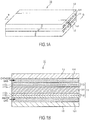
- FIG. 1A is a schematic perspective view of a fuel cell 10.
- FIG. 1B is a B-B sectional view of the fuel cell 10 of FIG. 1A .
- the fuel cell 10 is configured by arranging an anode separator 12 and a cathode separator 13 on both sides of a membrane electrode assembly (hereinafter, referred to as "MEA") 11.
- MEA membrane electrode assembly
- the MEA 11 is provided with an electrolyte membrane 111, an anode 112, and a cathode 113.
- the MEA 11 has the anode 112 on one side of the electrolyte membrane 111 and the cathode 113 on the other side thereof.
- the electrolyte membrane 111 is a proton-conducting ion-exchange membrane made by a fluorinated resin.
- the electrolyte membrane 111 shows an excellent electric conductivity in a wet condition.
- the anode 112 is provided with a catalyst layer 112a and a gas diffusion layer 112b.
- the catalyst layer 112a comes in contact with the electrolyte membrane 111.
- the catalyst layer 112a is made of platinum-supported carbon black particles or platinum, etc.-supported carbon black particles.
- the gas diffusion layer 112b is located outside of the catalyst layer 112a (the other side of the electrolyte 111), coming in contact with the anode separator 12.
- the gas diffusion layer 112b is formed by a member having a sufficient gas diffuseness and a conductive property, for example, a carbon cloth woven by yearns made of a carbon fiber.
- the cathode 113 is also provided with a catalyst layer 113a and a gas diffusion layer 113b along with the anode 112.
- the anode separator 12 comes in contact with the gas diffusion layer 112b.
- the anode separator 12 has a plurality of groove-like anode gas flow passages 121 for supplying anode gas to the anode 112 on the side coming in contact with the gas diffusion layer 112b.
- the cathode separator 13 comes in contact with the gas diffusion layer 113b.
- the cathode separator 13 has a plurality of groove-like cathode gas flow passages 131 for supplying cathode gas to the cathode 113 on the side coming in contact with the gas diffusion layer 113b.
- the anode gas flowing through the anode gas flow passages 121 and the cathode gas flowing through the cathode gas flow passages 131 flow in parallel to each other in the same direction. They may flow in parallel to each other in the reverse direction.
- a fuel cell stack with hundreds of fuel cells 10 piled up is used since large electric power is required. Then, electric power for driving a vehicle is taken by configuring a fuel cell system for supplying anode gas and cathode gas to the fuel cell stack.
- FIG. 2 is a schematic block diagram of an anode gas non-recycling fuel cell system 1 according to the embodiment of the present invention.
- the fuel cell system 1 is provided with a fuel cell stack 2, an anode gas supplier 3, and a controller 4.
- the fuel cell stack 2 formed by piling up a plurality of fuel cells 10 generates electric power by being supplied with anode gas and cathode gas, generating electric power required for driving a vehicle (for example, electric power required for driving a motor).
- the anode gas supplier 3 is provided with a high pressure tank 31, an anode gas supply passage 32, a pressure-adjusting valve 33, a pressure sensor 34, an anode gas discharge passage 35, a buffer tank 36, a purge passage 37, and a purge valve 38.
- the high pressure tank 31 stores the anode gas to be supplied to the fuel cell stack 2 while keeping it at a high pressure.
- the anode gas supply passage 32 is a passage for supplying the anode gas discharged from the high pressure tank 31 to the fuel cell stack 2, wherein one end of which is connected to the high pressure tank 31 and the other end of which is connected to an anode gas inlet hole 21 of the fuel cell stack 2.
- the pressure-adjusting valve 33 is located in the anode gas supply passage 32.
- the pressure-adjusting valve 33 adjusts the anode gas discharged from the high pressure tank 31 to the desired pressure, then, supplies it to the fuel cell stack 2.
- the pressure-adjusting valve 33 is an electromagnetic valve capable of continuously or step-by-step adjusting the aperture that is controlled by the controller 4.
- the pressure sensor 34 is located in the anode gas supply passage 32 located downstream of the pressure-adjusting valve 33.
- the pressure sensor 34 detects the pressure of the anode gas flowing through the anode gas supply passage 32 located downstream of the pressure-adjusting valve 33.
- the pressure of the anode gas detected by this pressure sensor 34 is used as the pressure of the entire anode system including respective anode gas flow passages 121 in the interior of the fuel cell stack and the buffer tank 36 (hereinafter, referred to as "an anode pressure").
- the anode gas discharge passage 35 has the end connected to an anode gas outlet hole 22 of the fuel cell stack 2 and the other end connected to the top of the buffer tank 36.
- the mixture gas of the redundant anode gas that has not been used for electrode reactions and the impure gas such as nitrogen and moisture that has transmitted from the cathode to the anode gas flow passage 121 (hereinafter, referred to as "anode-off gas") is discharged to the anode gas discharge passage 35.
- the buffer tank 36 once stores the anode-off gas that has flown through the anode gas discharge passage 35. Moisture in the anode-off gas partially becomes liquid water by being condensed in the buffer tank 36, being separated from the anode-off gas.
- the purge passage 37 has the end connected to the bottom of the buffer tank 36.
- the other end of the purge passage 37 is an opening end.
- the anode-off gas and liquid water stored in the buffer tank 36 are discharged from the opening end to external air through the purge passage 37. They are normally discharged to a cathode discharge line although not illustrated in FIG. 2 .
- the purge valve 38 is located in the purge passage 37.
- the purge valve 38 is an electromagnetic valve capable of continuously or step-by-step adjusting the aperture that is controlled by the controller 4.
- the amount of anode-off gas to be discharged from the buffer tank 36 to external air via the purge passage 37 is adjusted through adjustment of the aperture of the purge valve 38, further, the anode gas level in the buffer tank 36 is adjusted such that it becomes a constant level. If the operational status of the fuel cell system 1 is identical, the more the aperture of the purge valve 38 is increased, the more the nitrogen level in the buffer tank 36 is decreased and the more the anode gas level is increased.
- the controller 4 is configured by a microcontroller including a central processing unit (CPU), a random access memory (RAM), and an input/output interface (I/O interface).
- CPU central processing unit
- RAM random access memory
- I/O interface input/output interface
- the controller 4 receives signals for detecting the operational status of the fuel cell system 1 from a sensor, other than the above-descried pressure sensor 34, such as an electric current sensor 41 for detecting the output current of the fuel cell stack 2, a temperature sensor 42 for detecting a temperature of cooling water that cools the fuel cell stack 2 (hereinafter, referred to as "a stack temperature”), and an accelerator stroke sensor 43 for detecting the depression amount of the accelerator pedal (hereinafter, referred to as "accelerator operational amount").
- a sensor other than the above-descried pressure sensor 34
- an electric current sensor 41 for detecting the output current of the fuel cell stack 2
- a temperature sensor 42 for detecting a temperature of cooling water that cools the fuel cell stack 2
- an accelerator stroke sensor 43 for detecting the depression amount of the accelerator pedal
- the controller 4 carries out the pulsation operation for periodically increasing and decreasing the anode pressure by periodically opening and closing the pressure-adjusting valve 33 on the basis of these input signals and maintains the anode gas level in the buffer tank 36 at a specific level by adjusting the flowing amount of the anode gas to be discharged from the buffer tank 36 through adjustment of the purge valve 38.
- the anode-off gas containing the unused anode gas discharged from the fuel cell stack 2 wastefully continues to be discharged from the buffer tank 36 to external air via the purge passage 37.
- the pulsation operation for periodically increasing and decreasing the anode pressure is carried out by periodically opening and closing the pressure-adjusting valve 33. It is possible to allow the anode-off gas stored in the buffer tank 36 to flow backward to the fuel cell stack 2 upon reduction of the anode pressure by carrying out the pulsation operation. Thereby, it is possible to decrease the anode gas amount to be discharged to external air since the anode gas in the anode-off gas can be reused, and as a result, it can be more efficient.
- FIG. 3 is a view explaining the pulsation operation when the operation status of the fuel cell system 1 is a steady operation.
- the controller 4 computes the reference pressure and the width of the pulsation of the anode pressure on the basis of the load applied to the fuel cell stack 2 (hereinafter, referred to as "a stack load") (output current), setting the upper limit and the lower limit of the anode pressure. Then, the anode pressure is periodically increased and decreased between the upper limit and the lower limit of the set anode pressure by periodically increasing and decreasing the anode pressure within the range of the width of the pulsation on the basis of the reference pressure.
- a stack load output current
- the pressure-adjusting valve 33 is opened to at least the aperture at which the anode pressure can be increased to the upper limit. In this state, the anode gas is discharged to the buffer tank 36 after being supplied from the high pressure tank 31 to the fuel cell stack 2.
- the pressure-adjusting valve 33 is fully opened, stopping supply of anode gas from the high pressure tank 31 to the fuel cell stack 2. Then, since the anode gas left in the anode gas flow passage 121 in the interior of the fuel cell stack is consumed as time advances in accordance with the above-described electrode reaction (1), the anode pressure is reduced for the consumed amount of the anode gas.
- the anode-off gas flows backward from the buffer tank 36 to the anode gas flow passage 121 since the pressure of the buffer tank 36 becomes temporarily higher than the pressure of the anode gas flow passage 121.
- the anode gas left in the anode gas flow passage 121 and the anode gas in the anode-off gas flowed backward to the anode gas flow passage 121 are consumed as time advances and the anode pressure is further lowered.
- the pressure-adjusting valve 33 When the anode pressure reaches the lower limit at a time t3, the pressure-adjusting valve 33 is opened along with the case at the time t1. Then, if the anode pressure reaches the upper limit again at a time t4, the pressure-adjusting valve 33 is fully closed.
- the above-described reference pressure and width of the pulsation of the anode pressure are set on the basis of the premise that the temperature of the fuel cell stack 2 is identical to the temperature of the buffer tank 36. Specifically, they are set on the basis of the premise that the temperature of the buffer tank 36 is identical to the steady temperature of the fuel cell stack 2 when warming up of the fuel cell stack 2 is completed (about 60 C°).
- the temperature of the buffer tank 36 is sometimes lower than the steady temperature of the fuel cell stack 2 during warming up of the fuel cell stack 2.
- the temperature of the buffer tank 36 is sometimes lower or higher than the steady temperature of the fuel cell stack 2 since it is varied even after completion of worming up of the fuel cell stack 2 in accordance with the external environments such as an ambient temperature and an air resistance.
- the amount of material in the anode gas (hydrogen) located in the interior of the buffer tank 36 when the anode pressure reaches a specific upper limit pressure is varied in accordance with the temperature of the buffer tank 36. Specifically, if the pressure in the interior of the buffer tank 36 is the same, the lower the temperature of the buffer tank 36 becomes, the more the amount of material in the anode gas located in the interior of the buffer tank 36 is increased.
- the anode pressure is reduced from the upper limit pressure to the lower limit pressure upon reduction of the anode pressure by consuming the anode gas left in the anode gas flow passage 121 and the anode gas in the interior of the anode-off gas flowed backward to the anode gas flow passage 121. Therefore, the time required for lowering the anode pressure to the lower limit becomes long since the more the amount of material in the anode gas located in the interior of the buffer tank 36 is increased, the more the consumed amount of the anode gas needed for lowering the anode pressure to the lower limit is increased.
- FIG. 4 is a view explaining a reason why a part of which anode gas level is lower than those of other parts is locally generated within the anode gas flow passage 121.
- FIG. 4(A) is a view illustrating flows of the anode gas and the anode-off gas in the interior of the anode gas flow passage 121 upon reduction of the anode pressure.
- FIG. 4(B) is a view illustrating the level distribution of the anode gas in the interior of the anode gas flow passage 121 upon reduction of the anode pressure as time advances.
- the anode-off gas flows backward from the buffer tank 36 side to the anode gas flow passage 121 since the pressure of the buffer tank 36 is temporarily higher than that of the anode gas flow passage 121 if the anode gas left in the anode gas flow passage 121 is consumed.
- the high level of anode gas located in the anode gas supply passage 32 similarly flows into the anode gas flow passage 121 of which pressure is low.
- the anode gas level in the part where the anode gas level is lowest within the anode gas flow passage 121 (hereinafter, referred to as "the lowest anode gas level in the flow passage") is lower than the predetermined allowable lower limit anode gas level, the voltage is possibly turned into a negative voltage since the above-described electrode reactions (1) and (2) are prevented and this causes the deterioration of the fuel cell 10.
- the pulsation operation is carried out at the width of the pulsation that is set on the basis of the premise that the temperature of the buffer tank 36 is the steady temperature of the fuel cell stack 2 when the temperature of the buffer tank 36 is lower than the steady temperature of the fuel cell stack 2, the time required for lowering the anode pressure to the lower limit pressure becomes long, possibly causing the lowest anode gas level in the flow passage to fall below the allowable lower limit anode gas level.
- the time required for lowering the anode pressure to the lower limit pressure is shortened by correcting the width of the pulsation to be small,. Thereby, the lowest anode gas level in the flow passage is prevented from falling below the allowable lower limit anode gas level.
- FIG. 5 is a view illustrating the lowest anode gas level in the flow passage at the same width of the pulsation upon reduction of the anode pressure in accordance with the temperature of the buffer tank 36.
- the amount of material in the anode gas (hydrogen) located in the interior of the buffer tank 36 when the anode pressure reaches a specific upper limit pressure is varied in accordance with the temperature of the buffer tank 36. Specifically, if the pressure in the interior of the buffer tank 36 is the same, the higher the temperature of the buffer tank 36 becomes, the more the amount of material in the anode gas located in the interior of the buffer tank 36 is decreased.
- the pulsation operation is carried out at the width of the pulsation that is set on the basis of the premise that the temperature of the buffer tank 36 is identical to the steady temperature of the fuel cell stack 2 when the temperature of the buffer tank 36 is higher than the steady temperature of the fuel cell stack 2, the kinetic energy of the anode gas possibly falls below the minimum value of the kinetic energy required for discharging liquid water in the interior of the anode gas flow passage 121 (hereinafter, referred to as "the allowable lower limit kinetic energy").
- the kinetic energy of the anode gas is ensured by adjusting the width of the pulsation to be large when the temperature of the buffer tank 36 is high.
- FIG. 6 is a view illustrating the intensity of kinetic energy of the anode gas at the same width of the pulsation upon increase of the anode pressure in accordance with the temperature of the buffer tank 36.
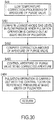
- FIG. 7 is a flowchart explaining the control of the pulsation operation according to the present embodiment of the present invention.
- the controller 4 repeatedly carries out the present routine for each specific time (for example, 10ms).
- the controller 4 reads the output current, a stack temperature, an ambient temperature, and a vehicle speed as a stack load in Step S1.
- the controller 4 computes the reference pressure of the anode pressure in the pulsation operation on the basis of the output current with reference to the table illustrated in FIG. 8 in Step S2. As illustrated in FIG. 8 , the larger the output current is, the more the reference pressure of the anode pressure is increased.
- the controller 4 computes the basic value of the width of the pulsation (hereinafter, referred to as "a basic width of the pulsation") in the pulsation operation on the basis of the output current with reference to the table illustrated in FIG. 9 in Step S3. As illustrated in FIG. 9 , the larger the output current is, the more the basic width of the pulsation is increased.
- the controller 4 computes the basic aperture of the purge valve on the basis of the stack temperature with reference to the table illustrated in FIG. 10 in Step S4. As illustrated in FIG. 10 , the higher the stack temperature is, the more the basic aperture of the purge valve is increased.
- the controller 4 computes the temperature of the buffer tank 36 in Step S5. According to the present embodiment, the controller 4 computes the temperature of the buffer tank 36 on the basis of a stack temperature, an ambient temperature, and a vehicle speed.
- the controller 4 determines whether or not the temperature of the buffer tank 36 is higher than a first specific temperature in step S6.
- the first specific temperature is set at a temperature higher than the steady temperature of the fuel cell stack 2 when the warming up thereof is completed (about 60 °C).
- the controller 4 carries out the processing of Step S10 if the temperature of the buffer tank 36 is higher than the first specific temperature and carries out the processing of Step S7 if it is lower than the first specific temperature.
- the controller 4 determines whether or not the temperature of the buffer tank 36 is lower than a second specific temperature in step S7.
- the second specific temperature is set at a temperature lower than the steady temperature of the fuel cell stack 2 when the warming up thereof is completed.
- the controller 4 carries out the processing of Step S9 if the temperature of the buffer tank 36 is lower than the second specific temperature and carries out the processing of Step S8 if it is higher than the second specific temperature.
- the controller 4 carries out the pulsation operation by periodically increasing and decreasing the anode pressure with the central focus on the reference pressure within the range of the basic width of the pulsation in Step S8 after determining that the temperature of the buffer tank 36 is substantially identical to the steady temperature of the fuel cell stack 2.
- the controller 4 determines that the temperature of the buffer tank 36 is lower than the steady temperature of the fuel cell stack 2 in Step S9, carrying out the low temperature pulsation width correction processing in order to make the width of the pulsation smaller than the basic width of the pulsation.
- the low temperature pulsation width correction processing will be later described with reference to FIG. 11 .
- the controller 4 carries out the high temperature pulsation width correction processing in order to make the width of the pulsation larger than the basic width of the pulsation in Step S10 after determining that the temperature of the buffer tank 36 is lower than the steady temperature of the fuel cell stack 2.
- the high temperature pulsation width correction processing will be later described with reference to FIG. 13 .
- the controller 4 controls the aperture of the purge valve to be a basic aperture in Step S11.
- FIG. 11 is a flowchart explaining the low temperature pulsation width correction processing.
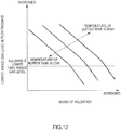
- the controller 4 computes the maximum value of the width of the pulsation at which the lowest anode gas level in the flow passage does not fall below the allowable lower limit anode gas level (hereinafter, referred to as "the allowable maximum width of the pulsation") on the basis of the temperature of the buffer tank 36 with reference to the map illustrated in FIG. 12 in Step S91.
- FIG. 12 is a map representing a relation between the width of the pulsation and the lowest anode gas level in the flow passage upon reduction of the anode pressure for each temperature of the buffer tank 36.
- the lowest anode gas level in the flow passage becomes high since the smaller the width of the pulsation is, the shorter the time required for lowering the anode pressure to the lower limit pressure becomes.
- the width of the pulsation is the same, the lowest anode gas level in the flow passage becomes low since the lower the temperature of the buffer tank 36 is, the more the amount of material in the anode gas located in the interior of the buffer tank 36 is increased and the longer the time required for lowering the anode pressure to the lower limit pressure becomes.
- the controller 4 carries out the pulsation operation by periodically increasing and decreasing the anode pressure within the range of the allowable minimum width of the pulsation with the central focus on the reference pressure in Step S92.
- the controller 4 controls the aperture of the purge valve to be the basic aperture in Step S93.
- FIG. 13 is a flowchart explaining the high temperature pulsation width correction processing.
- the controller 4 computes the allowable lower limit kinetic energy on the basis of the output current with reference to the table illustrated in FIG. 14 in Step S10. As illustrated in FIG. 14 , the larger the output current is, the more the allowable lower limit kinetic energy is increased. This is because the larger the output current is, the more water is produced by the above-described electrode reaction (2).
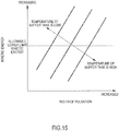
- the controller 4 computes the minimum value of the width of the pulsation that does not fall below the allowable lower limit kinetic energy (hereinafter, referred to as "the allowable minimum width of the pulsation") on the basis of the temperature of the buffer tank 36 with reference to the map illustrated in FIG. 15 in Step S102.
- FIG. 15 is a map representing a relation between the width of the pulsation and the kinetic energy of the anode gas upon increase of the anode pressure for each temperature of the buffer tank 36.
- the kinetic energy of the anode gas is decreased since the smaller the width of the pulsation is, the smaller the amount of the anode gas required for increasing the anode pressure to the upper limit pressure becomes.
- the kinetic energy of the anode gas is decreased since the higher the temperature of the buffer tank 36 is, the smaller the amount of the anode gas required for increasing the anode pressure to the upper limit pressure becomes.
- the controller 4 carries out the pulsation operation by periodically increasing and decreasing the anode pressure within the range of the allowable minimum width of the pulsation with the central focus on the reference pressure in Step S103.
- the controller 4 controls the aperture of the purge valve to be the basic aperture in Step S104.
- FIG. 16 is a view explaining the action of the low temperature pulsation width correction processing according to the present embodiment.
- a thin solid line illustrates the lowest anode gas level in the flow passage when the temperature of the buffer tank 36 is the steady temperature of the fuel cell stack 2 in accordance with the width of the pulsation.
- a bold line illustrates the lowest anode gas level in the flow passage when the temperature of the buffer tank 36 is a specific temperature that is lower than the steady temperature of the fuel cell stack 2, namely, a specific temperature that is lower than the second specific temperature in accordance with the width of the pulsation.
- the width of the pulsation in the pulsation operation is corrected to be smaller than the basic width of the pulsation on the basis of the temperature of the buffer tank 36 when the temperature of the buffer tank 36 is lower than the steady temperature of the fuel cell stack 2.
- the controller 4 computes the allowable maximum width of the pulsation at which the lowest anode gas level in the flow passage becomes the allowable lower limit anode gas level on the basis of the temperature of the buffer tank 36, carrying out the pulsation operation at the computed allowable maximum width of the pulsation. Thereby, it is possible to prevent the lowest anode gas level in the flow passage from falling below the allowable lower limit anode gas level upon reduction of the anode pressure.
- FIG. 17 is a view explaining the action of the high temperature pulsation width correction processing according to the present embodiment.
- a thin solid line illustrates the kinetic energy of the anode gas when the temperature of the buffer tank 36 is the steady temperature of the fuel cell stack 2 in accordance with the width of the pulsation.
- a bold line illustrates the kinetic energy of the anode gas when the temperature of the buffer tank 36 is a specific temperature that is higher than the steady temperature of the fuel cell stack 2, namely, a specific temperature that is higher than the first specific temperature, in accordance with the width of the pulsation.
- the width of the pulsation in the pulsation operation is corrected to be larger than the basic width of the pulsation on the basis of the temperature of the buffer tank 36 when the temperature of the buffer tank 36 is higher than the steady temperature of the fuel cell stack 2.
- the controller 4 computes the allowable minimum width of the pulsation at which the kinetic energy of the anode gas becomes the allowable lower limit kinetic energy on the basis of the temperature of the buffer tank 36, carrying out the pulsation operation at the computed allowable minimum width of the pulsation. Thereby, it is possible to prevent the kinetic energy of the anode gas from falling below the allowable lower limit kinetic energy upon increase of the anode pressure.
- the width of the pulsation in the case of carrying out the pulsation operation is corrected on the basis of the temperature of the buffer tank 36.
- the width of the pulsation in the pulsation operation is made smaller than the width of the pulsation that is set when the temperature of the buffer tank 36 is substantially identical to the steady temperature of the fuel cell stack 2.
- the width of the pulsation in the pulsation operation is made larger than the width of the pulsation that is set when the temperature of the buffer tank 36 is substantially identical to the steady temperature of the fuel cell stack 2.
- the present embodiment is different from the first embodiment in that the aperture of the purge valve 38 is corrected in accordance with the moisture status of the electrolyte membrane 111.
- the different point will be mainly described.
- the parts with the same functions as the above-described first embodiment are provided with the same reference codes and the description thereof is herein omitted.
- the width of the pulsation in the pulsation operation is smaller than the width of the pulsation that is set when the temperature of the buffer tank 36 is substantially identical to the steady temperature of the fuel cell stack 2.
- the width of the pulsation in the pulsation operation is made small, the kinetic energy of the anode gas upon increase of the anode pressure is decreased, then the discharge performance of liquid water in the interior of the anode gas flow passage 121 is deteriorated. Accordingly, when the electrolyte membrane 111 is in a wet state with a high water content, it is preferable that the reduced width from the basic width of the pulsation is made small as much as possible.
- FIG. 18 is a view illustrating a relation between a width of the pulsation and the lowest anode gas level in the flow passage when the temperature of the buffer tank 36 is a specific temperature in accordance with the aperture of a purge valve 38.
- the anode gas level in the interior of the purge valve 38 is made higher than usual by increasing the aperture of the purge valve 38. Therefore, it is possible to increase the allowable maximum width of the pulsation, making it possible to reduce the reduced width in the width of the pulsation from the basic width of the pulsation.
- FIG. 19 is a flowchart explaining the low temperature pulsation width correction processing according to the present embodiment.
- the controller 4 computes an inner high frequency resistance (HFR: High Frequency Resistance) (hereinafter, referred to as "an inner resistance”) of the fuel cell stack 2 in order to determine the moisture status of the electrolyte membrane 111 in Step S291. It has been known that there is a correlation between the moisture status of the electrolyte membrane 111 and the inner resistance of the fuel cell stack 2, in which correlation, the lower the inner resistance of the fuel cell stack 2 is, the more the moisture in the membrane exists, then the electrolyte membrane 111 is in the moisture status.
- HFR High Frequency Resistance
- the controller 4 determines whether or not the inner resistance of the fuel cell stack 2 is smaller than a specific value in Step S292.
- the controller 4 determines that the electrolyte membrane 111 is in the moisture status if the inner resistance of the fuel cell stack 2 is smaller than the specific value, carrying out the processing of Step S293. On the other hand, if the inner resistance of the fuel cell stack 2 is not less than the specific value, the controller 4 carries out the processing of Step S91.
- the controller 4 computes the correction amount of the aperture of the purge valve 38 on the basis of the inner resistance of the fuel cell stack 2 with reference to the table illustrated in FIG. 20 in Step S293. As illustrated in FIG. 20 , the smaller the inner resistance of the fuel cell stack 2 is, namely, the more the moisture in the membrane of the electrolyte membrane 111 exists, the aperture of the purge valve 38 is increased by increasing the correction amount of the aperture of the purge valve 38.
- the controller 4 computes the correction amount of the allowable maximum width of the pulsation on the basis of the correction amount of the aperture of the purge valve 38 with reference to the table illustrated in FIG. 21 in Step S294. As illustrated in FIG. 21 , the larger the correction amount of the aperture of the purge valve 38 is, the larger the correction amount of the allowable maximum width of the pulsation becomes.
- the controller 4 carries out the pulsation operation at the width of the pulsation in which the correction amount is added to the allowable maximum width of the pulsation (hereinafter, referred to as "a corrected allowable maximum width of the pulsation") with the central focus on the reference pressure in Step S295.
- the controller 4 controls the aperture of the purge valve 38 to be the corrected aperture in which the correction amount of the aperture is added to the basic aperture in Step S296.
- FIG. 22 is a view explaining the action of the low temperature pulsation width correction processing according to the present embodiment.
- a thin solid line illustrates the lowest anode gas level in the flow passage when the temperature of the buffer tank is a specific temperature that is lower than the steady temperature of the fuel cell stack and the aperture of the purge valve is a basic aperture in accordance with the width of the pulsation.
- a bold line illustrates the lowest anode gas level in the flow passage when the temperature of the buffer tank is a specific temperature that is lower than the steady temperature of the fuel cell stack and the aperture of the purge valve is larger than the basic aperture in accordance with the width of the pulsation.
- the aperture of the purge valve 38 is made larger than the basic aperture in accordance with the inner resistance of the fuel cell stack 2.
- the same advantages as the first embodiment can be obtained and further, the discharge performance of liquid water when the electrolyte membrane 111 is in the moisture status can be improved and this makes it possible to further prevent flooding from being generated in the anode gas flow passage 121.
- the present embodiment is different from the first embodiment in that the width of the pulsation is made larger and the aperture of the purge valve 38 is corrected upon carrying out the high temperature pulsation width correction processing.
- the different point will be mainly described.
- FIG. 23 is a view illustrating a relation between the width of the pulsation, the kinetic energy of the anode gas, and the lowest anode gas level in the flow passage when the temperature of the buffer tank 36 is a specific temperature that is higher than the steady temperature of the fuel cell stack 2.
- the pulsation operation is carried out at the allowable minimum width of the pulsation by correcting the width of the pulsation in the pulsation operation to be larger than the basic width of the pulsation in order to prevent the kinetic energy of the anode gas does from falling below the allowable lower limit kinetic energy,.
- the allowable lower limit kinetic energy is varied in accordance with the operation status of the fuel cell system. Therefore, as illustrated in FIG. 23 , in the case that the allowable lower limit kinetic energy is comparatively small, the lowest anode gas level in the flow passage when the pulsation operation is carried out at the allowable minimum width of the pulsation is sometimes higher than the allowable lower limit anode gas level.
- the lowest anode gas level in the flow passage when the pulsation operation is carried out at the allowable minimum width of the pulsation is sometimes lower than the allowable lower limit anode gas level.
- the aperture of the purge valve 38 is made smaller than the basic aperture in order to decrease the lowest anode gas level in the flow passage to the allowable lower limit anode gas level.
- the aperture of the purge valve 38 is made larger than the basic aperture in order to increase the lowest anode gas level in the flow passage to the allowable lower limit anode gas level.
- FIG. 24 is a flowchart explaining the high temperature pulsation width correction processing according to the present embodiment.
- the controller 4 computes the lowest anode gas level in the flow passage during the pulsation operation at the allowable minimum width of the pulsation with reference to the above-described map of FIG. 12 in Step S301.
- the controller 4 determines whether or not the computed lowest anode gas level in the flow passage is not less than the allowable lower limit anode gas level in Step S302.
- the controller 4 carries out the processing of Step S303 if the computed lowest anode gas level in the flow passage is not less than the allowable lower limit anode gas level.
- the processing of Step S306 is carried out.
- the controller 4 computes the correction amount of the aperture of the purge valve 38 on the basis of the difference in level obtained by subtracting the allowable lower limit anode gas level from the computed lowest anode gas level in the flow passage with reference to the table illustrated in FIG. 25 in Step S303.
- the correction amount of the aperture of the purge valve 38 is set such that the larger the level difference becomes, the smaller the aperture of the purge valve 38 becomes compared to the basic aperture.
- the controller 4 makes the aperture of the purge valve 38 to be the corrected aperture in which the correction amount of the aperture is added to the basic aperture of the purge valve 38 in Step S304.
- the controller 4 carries out the pulsation operation at the allowable maximum width of the pulsation with the central focus on the reference pressure in Step S305.
- the controller 4 computes the correction amount of the aperture of the purge valve 38 on the basis of the difference in level obtained by subtracting the allowable lower limit anode gas level from the computed lowest anode gas level in the flow passage with reference to the table illustrated in FIG. 26 in Step S306. As illustrated in FIG. 26 , the correction amount of the aperture of the purge valve 38 is set such that the larger the level difference becomes, the larger the aperture of the purge valve 38 becomes compared to the basic aperture.
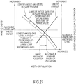
- FIG. 27 is a view explaining the action in the case that the lowest anode gas level in the flow passage during the pulsation operation at the allowable minimum width of the pulsation is higher than the allowable lower limit anode gas level.
- the aperture of the purge valve 38 is made smaller than the basic aperture in order to decrease the lowest anode gas level in the flow passage to the allowable lower limit anode gas level.
- FIG. 28 is a view explaining the action in the case that the lowest anode gas level in the flow passage during the pulsation operation at the allowable minimum width of the pulsation is the allowable lower limit anode gas level.
- the aperture of the purge valve 38 is made larger than the basic aperture in order to increase the lowest anode gas level in the flow passage to the allowable lower limit anode gas level.
- the width of the pulsation in the pulsation operation is corrected to be larger than the basic width of the pulsation in order to prevent the kinetic energy of the anode gas from falling below the allowable lower limit kinetic energy, carrying out the pulsation operation at the allowable minimum width of the pulsation.
- the aperture of the purge valve 38 is made smaller than the basic aperture in order to decrease the lowest anode gas level in the flow passage to the allowable lower limit anode gas level.
- the aperture of the purge valve 38 is made larger than the basic aperture in order to increase the lowest anode gas level in the flow passage to the allowable lower limit anode gas level.
- the present embodiment is different from the first embodiment in that the aperture of purge valve 38 is only corrected in order to prevent the lowest anode gas level in the flow passage from falling below the allowable lower limit anode gas level when the temperature of the buffer tank 36 is lower than the steady temperature of the fuel cell stack 2.
- the different point will be mainly described.
- FIG. 29 is a flowchart explaining the control of the pulsation operation according to the present embodiment.
- the controller 4 repeatedly carries out the present routine for each specific time (for example, 10ms).
- the controller 4 carries out the low temperature pulsation width correction processing in Step S49.
- FIG. 30 is a flowchart explaining the low temperature correction processing of the aperture of the purge valve.
- the controller 4 computes the lowest anode gas level in the flow passage during the pulsation operation at the basic width of the pulsation with reference to the above-described map of FIG. 12 in Step S491.
- the controller 4 computes the correction amount of the aperture of the purge valve 38 on the basis of the difference in level obtained by subtracting the allowable lower limit anode gas level from the computed lowest anode gas level in the flow passage with reference to the table illustrated in FIG. 31 in Step S492. As illustrated in FIG. 31 , the correction amount of the aperture of the purge valve 38 is computed such that the larger the level difference becomes, the larger the aperture of the purge valve 38 becomes compared to the basic aperture.
- the controller 4 makes the aperture of the purge valve 38 to be the corrected aperture in which the correction amount of the aperture is added to the basic aperture of the purge valve 38 in Step S493.
- the controller 4 carries out the pulsation operation at the basic width of the pulsation with the central focus on the reference pressure in Step S494.
- FIG. 32 is a view explaining the action of the low temperature correction processing of the aperture of the purge valve according to the present embodiment, namely, a view explaining a relation between the width of the pulsation and the lowest anode gas level in the flow passage when the temperature of the buffer tank 36 is a specific temperature lower than the steady temperature of the fuel cell stack 2.
- the pulsation operation is carried out at the basic width of the pulsation when the temperature of the buffer tank 36 is lower than the steady temperature of the fuel cell stack 2, the lowest anode gas level in the flow passage becomes lower than the allowable lower limit anode gas level.
- the aperture of the purge valve 38 is made larger than the basic aperture in order to increase the lowest anode gas level in the flow passage to the allowable lower limit anode gas level.
- the temperature of the buffer tank 36 is computed by the operation; however, the present invention is not limited to this.
- the temperature of the buffer tank 36 may be directly detected by providing a temperature sensor to the buffer tank 36.
- the width of the pulsation is corrected on the basis of the temperature of the buffer tank 36; however, the present invention is not limited to this.
- the width of the pulsation may be corrected on the basis of the temperature of this upper buffer volume as is the case with the above-described respective embodiments.
- the width of the pulsation may be corrected in accordance with the difference in temperature between the fuel cell stack 2 and the buffer tank 36.
- the pulsation operation may be carried out at the allowable maximum width of the pulsation in order to prevent the lowest anode gas level in the flow passage from falling below the allowable lower limit anode gas level by correcting the width of the pulsation to be smaller than the basic width of the pulsation when the temperature of the buffer tank 36 is lower than that of the fuel cell stack 2; however, the present invention is not limited to this.
- the pulsation operation may be carried out while decreasing the width of the pulsation less than the allowable maximum width of the pulsation since the smaller the width of the pulsation is, the higher the anode gas level in the flow passage becomes.
Landscapes
- Life Sciences & Earth Sciences (AREA)
- Engineering & Computer Science (AREA)
- Manufacturing & Machinery (AREA)
- Sustainable Development (AREA)
- Sustainable Energy (AREA)
- Chemical & Material Sciences (AREA)
- Chemical Kinetics & Catalysis (AREA)
- Electrochemistry (AREA)
- General Chemical & Material Sciences (AREA)
- Fuel Cell (AREA)
Claims (10)
- Système de pile à combustible (1) qui génère de l'énergie électrique en fournissant du gaz anodique et du gaz cathodique à une pile à combustible (10), comprenant :une soupape de commande (33) adaptée pour régler la pression du gaz anodique devant être fourni à la pile à combustible (10) ;une unité tampon (36) adaptée pour stocker le gaz de dégagement anodique devant être évacué de la pile à combustible (10) ; etune unité d'opération de pulsation (4) adaptée pour commander la soupape de commande (33) afin d'augmenter et de diminuer périodiquement la pression du gaz anodique à une largeur spécifique de la pulsation ;caractérisé parune unité de correction de largeur de pulsation (4) adaptée pour corriger la largeur de la pulsation sur la base de la température de l'unité tampon (36).
- Système de pile à combustible (1) selon la revendication 1,
dans lequel l'unité de correction de largeur de pulsation (4) diminue la largeur de la pulsation afin d'empêcher le niveau de gaz anodique dans le passage d'écoulement de gaz anodique dans la pile à combustible (10) de tomber en dessous d'un niveau de limite inférieure admissible spécifique lorsque la température de l'unité tampon (36) est inférieure à la température constante de la pile à combustible (10). - Système de pile à combustible (1) selon la revendication 2,
dans lequel l'unité de correction de largeur de pulsation (4) définit une limite inférieure de la largeur de la pulsation dans le cas d'une diminution de la largeur de la pulsation afin d'empêcher l'énergie cinétique du gaz anodique circulant à travers le passage d'écoulement de gaz anodique dans la pile à combustible (10) de tomber en dessous d'une énergie cinétique de limite inférieure admissible qui permet d'évacuer l'eau liquide située dans le passage de gaz anodique vers l'unité tampon (36). - Système de pile à combustible (1) selon la revendication 2 ou 3, comprenant :une soupape de purge (38) adaptée pour réguler le débit du gaz de dégagement anodique devant être évacué de l'unité tampon (36) ;une unité de commande de soupape de purge (4) adaptée pour régler la soupape de purge (38) à une ouverture en fonction de l'état de fonctionnement du système de pile à combustible (1) afin d'amener le niveau de gaz anodique dans l'unité tampon (36) à un niveau spécifique ;une unité de détermination d'état d'humidité (4) adaptée pour déterminer l'état d'humidité de la pile à combustible (10) ; etune unité de correction d'ouverture de purge d'état humidité (4) adaptée pour rendre le niveau de gaz anodique dans l'unité tampon (36) plus élevé que le niveau spécifique en augmentant l'ouverture de la soupape de purge (38) et pour diminuer la largeur réduite lors de la diminution de la largeur de la pulsation sur la base de l'état d'humidité de la pile à combustible (10).
- Système de pile à combustible (1) selon l'une quelconque des revendications 1 à 4,
dans lequel l'unité de correction de largeur de pulsation (4) augmente la largeur de la pulsation afin d'empêcher l'énergie cinétique du gaz anodique circulant à travers le passage d'écoulement de gaz anodique dans la pile à combustible (10) de tomber en dessous d'une énergie cinétique de limite inférieure admissible qui permet d'évacuer l'eau liquide située dans le passage de gaz anodique vers l'unité tampon (36) lorsque la température de l'unité tampon (36) est supérieure à la température constante de la pile à combustible (10). - Système de pile à combustible (1) selon la revendication 5, comprenant :une soupape de purge (38) adaptée pour réguler le débit du gaz de dégagement anodique devant être évacué de l'unité tampon (36) ;une unité de commande de soupape de purge (4) adaptée pour régler la soupape de purge (38) à une ouverture en fonction de l'état de fonctionnement du système de pile à combustible (1) afin d'amener le niveau de gaz anodique dans l'unité tampon (36) à un niveau spécifique ;une unité de calcul de niveau le plus bas (4) adaptée pour calculer le niveau le plus bas du passage d'écoulement de gaz anodique dans la pile à combustible (10) pendant l'opération de pulsation à la largeur de la pulsation qui est corrigée par l'unité de correction de largeur de pulsation (4) de sorte qu'elle devienne grande ; etune unité de correction d'ouverture de purge à haute température (4) adaptée pour corriger l'ouverture de la soupape (38) en fonction du niveau le plus bas calculé.
- Système de pile à combustible (1) selon la revendication 6,
dans lequel l'unité de correction d'ouverture de purge à haute température (4), lorsque le niveau le plus bas calculé est supérieur à un niveau de limite inférieure admissible spécifique, rend le niveau de gaz anodique dans l'unité tampon (36) inférieur au niveau spécifique en diminuant l'ouverture de la soupape de purge (38) afin de diminuer le niveau le plus bas du passage d'écoulement de gaz anodique dans la pile à combustible (10) pendant l'opération de pulsation à la largeur corrigée de la pulsation au niveau de limite inférieure admissible. - Système de pile à combustible (1) selon la revendication 6 ou 7,
dans lequel l'unité de correction d'ouverture de purge à haute température (4), lorsque le niveau le plus bas calculé est inférieur à un niveau de limite inférieure admissible spécifique, rend le niveau de gaz anodique dans l'unité tampon (36) supérieur au niveau spécifique en augmentant l'ouverture de la soupape de purge (38) afin d'augmenter le niveau le plus bas du passage d'écoulement de gaz anodique dans la pile à combustible (10) pendant l'opération de pulsation à la largeur corrigée de la pulsation au niveau de limite inférieure admissible. - Système de pile à combustible (1) qui génère de l'énergie électrique en fournissant du gaz anodique et du gaz cathodique à une pile à combustible, comprenant :une soupape de commande (33) adaptée pour régler la pression du gaz anodique devant être fourni à la pile à combustible (10) ;une unité tampon (36) adaptée pour stocker le gaz de dégagement anodique devant être évacué de la pile à combustible (10) ; etune unité d'opération de pulsation (4) adaptée pour commander la soupape de commande (33) afin d'augmenter et de diminuer périodiquement la pression du gaz anodique à une largeur spécifique de la pulsation ; etune unité de correction de largeur de pulsation (4) adaptée pour corriger la largeur de la pulsation sur la base de la température du volume du passage d'écoulement de gaz anodique de la soupape de commande (33) à la pile à combustible (10).
- Système de pile à combustible (1) selon l'une quelconque des revendications 1 à 9,
dans lequel plus la charge de la pile à combustible (10) est élevée, plus l'unité d'opération de pulsation (4) augmente la largeur de la pulsation.
Applications Claiming Priority (2)
| Application Number | Priority Date | Filing Date | Title |
|---|---|---|---|
| JP2011124220 | 2011-06-02 | ||
| PCT/JP2012/060350 WO2012165073A1 (fr) | 2011-06-02 | 2012-04-17 | Système de pile à combustible |
Publications (3)
| Publication Number | Publication Date |
|---|---|
| EP2717371A1 EP2717371A1 (fr) | 2014-04-09 |
| EP2717371A4 EP2717371A4 (fr) | 2014-12-17 |
| EP2717371B1 true EP2717371B1 (fr) | 2018-09-05 |
Family
ID=47258937
Family Applications (1)
| Application Number | Title | Priority Date | Filing Date |
|---|---|---|---|
| EP12793754.8A Active EP2717371B1 (fr) | 2011-06-02 | 2012-04-17 | Système de pile à combustible |
Country Status (6)
| Country | Link |
|---|---|
| US (2) | US9812718B2 (fr) |
| EP (1) | EP2717371B1 (fr) |
| JP (1) | JP5737395B2 (fr) |
| CN (1) | CN103582970B (fr) |
| CA (1) | CA2837838C (fr) |
| WO (1) | WO2012165073A1 (fr) |
Families Citing this family (7)
| Publication number | Priority date | Publication date | Assignee | Title |
|---|---|---|---|---|
| WO2013137431A1 (fr) * | 2012-03-15 | 2013-09-19 | 日産自動車株式会社 | Système de pile à combustible |
| KR101459849B1 (ko) * | 2012-12-14 | 2014-11-07 | 현대자동차주식회사 | 연료전지 시스템의 맥동 운전 방법 |
| GB2518681B (en) * | 2013-09-30 | 2021-08-25 | Intelligent Energy Ltd | Anode bleed control in a fuel cell stack |
| WO2015170416A1 (fr) * | 2014-05-09 | 2015-11-12 | 日産自動車株式会社 | Système de pile à combustible et son procédé de commande |
| DE102020115789A1 (de) | 2020-06-16 | 2021-12-16 | Audi Aktiengesellschaft | Verfahren zum Betreiben einer Brennstoffzellenvorrichtung, Brennstoffzellenvorrichtung sowie Brennstoffzellenfahrzeug |
| CN113764703B (zh) * | 2021-11-09 | 2022-02-01 | 北京新研创能科技有限公司 | 燃料电池阳极脉冲排放控制方法、装置及可读存储介质 |
| CN114512692B (zh) * | 2022-01-28 | 2024-04-26 | 上海捷氢科技股份有限公司 | 一种燃料电池的吹扫方法、燃料电池系统和燃料电池车辆 |
Family Cites Families (17)
| Publication number | Priority date | Publication date | Assignee | Title |
|---|---|---|---|---|
| JP3555160B2 (ja) | 1994-02-08 | 2004-08-18 | トヨタ自動車株式会社 | 燃料電池装置 |
| JP4214761B2 (ja) * | 2002-01-31 | 2009-01-28 | 株式会社デンソー | 燃料電池システム |
| JP4649861B2 (ja) * | 2003-09-09 | 2011-03-16 | トヨタ自動車株式会社 | 燃料電池システム |
| US20050142400A1 (en) | 2003-12-31 | 2005-06-30 | Nuvera Fuel Cells | Safe purging of water from fuel cell stacks |
| JP4631292B2 (ja) | 2004-02-27 | 2011-02-16 | トヨタ自動車株式会社 | 燃料電池システム |
| EP1727227B1 (fr) * | 2004-03-17 | 2011-01-26 | Toyota Jidosha Kabushiki Kaisha | Système de pila à combustile |
| JP2006248814A (ja) * | 2005-03-09 | 2006-09-21 | Hitachi Ltd | 水素供給装置および水素供給方法 |
| JP2007323959A (ja) * | 2006-05-31 | 2007-12-13 | Toyota Motor Corp | 燃料電池システム |
| JP2008097966A (ja) | 2006-10-11 | 2008-04-24 | Toyota Motor Corp | 燃料電池システム、および、その制御方法 |
| JP2008300057A (ja) * | 2007-05-29 | 2008-12-11 | Toyota Motor Corp | 燃料電池システム |
| JP2009123457A (ja) * | 2007-11-14 | 2009-06-04 | Toyota Motor Corp | 燃料電池システム |
| CA2744304C (fr) * | 2008-11-21 | 2013-12-10 | Nissan Motor Co., Ltd. | Commande de pile a combustible a cycle de pression d'anode |
| JP5428307B2 (ja) | 2008-11-27 | 2014-02-26 | 日産自動車株式会社 | 燃料電池システム |
| JP5347719B2 (ja) * | 2009-05-28 | 2013-11-20 | 日産自動車株式会社 | 燃料電池装置 |
| US8795912B2 (en) * | 2009-06-16 | 2014-08-05 | Shell Oil Company | Systems and processes for operating fuel cell systems |
| JP5481991B2 (ja) * | 2009-07-23 | 2014-04-23 | 日産自動車株式会社 | 燃料電池システム及び燃料電池システムの運転方法 |
| WO2012033003A1 (fr) * | 2010-09-09 | 2012-03-15 | 日産自動車株式会社 | Système de piles à combustible et son procédé de fonctionnement |
-
2012
- 2012-04-17 CN CN201280027037.2A patent/CN103582970B/zh active Active
- 2012-04-17 US US14/122,790 patent/US9812718B2/en active Active
- 2012-04-17 WO PCT/JP2012/060350 patent/WO2012165073A1/fr active Application Filing
- 2012-04-17 EP EP12793754.8A patent/EP2717371B1/fr active Active
- 2012-04-17 JP JP2013517922A patent/JP5737395B2/ja not_active Expired - Fee Related
- 2012-04-17 CA CA2837838A patent/CA2837838C/fr active Active
-
2017
- 2017-09-14 US US15/704,558 patent/US10193168B2/en active Active
Non-Patent Citations (1)
| Title |
|---|
| None * |
Also Published As
| Publication number | Publication date |
|---|---|
| US20180006318A1 (en) | 2018-01-04 |
| US9812718B2 (en) | 2017-11-07 |
| CN103582970A (zh) | 2014-02-12 |
| EP2717371A1 (fr) | 2014-04-09 |
| US20140093803A1 (en) | 2014-04-03 |
| JP5737395B2 (ja) | 2015-06-17 |
| WO2012165073A1 (fr) | 2012-12-06 |
| CA2837838C (fr) | 2017-08-15 |
| CA2837838A1 (fr) | 2012-12-06 |
| CN103582970B (zh) | 2016-06-29 |
| US10193168B2 (en) | 2019-01-29 |
| JPWO2012165073A1 (ja) | 2015-02-23 |
| EP2717371A4 (fr) | 2014-12-17 |
Similar Documents
| Publication | Publication Date | Title |
|---|---|---|
| US10193168B2 (en) | Fuel cell system | |
| JP4548453B2 (ja) | 燃料電池システムおよび燃料電池システムの制御装置 | |
| JP5812118B2 (ja) | 燃料電池システム | |
| JP5704228B2 (ja) | 燃料電池システム | |
| WO2013129553A1 (fr) | Système de pile à combustible et procédé de commande pour système de pile à combustible | |
| WO2013129453A1 (fr) | Système de pile à combustible et procédé de commande pour système de pile à combustible | |
| JP2009295505A (ja) | 燃料電池システム | |
| JPWO2008007690A1 (ja) | 燃料電池システム | |
| JP2008269911A (ja) | 燃料電池システムおよび燃料電池システムにおけるガス圧力調節方法 | |
| WO2013137017A1 (fr) | Système de pile à combustible et procédé de commande pour système de pile à combustible | |
| JP4085805B2 (ja) | 燃料電池システム | |
| JP2009016155A (ja) | 燃料電池の制御装置および燃料電池システム | |
| JP5783974B2 (ja) | 燃料電池システムの起動方法および燃料電池システム | |
| JP6304366B2 (ja) | 燃料電池システム | |
| JP5080876B2 (ja) | 燃料電池システム | |
| JP6136185B2 (ja) | 燃料電池システム | |
| JP4956481B2 (ja) | 燃料電池システム及び燃料電池システムの制御方法 | |
| JP4675605B2 (ja) | 燃料電池の酸化剤供給装置 | |
| JP2014241260A (ja) | 燃料電池システム | |
| JP6287010B2 (ja) | 燃料電池システム | |
| JP5509728B2 (ja) | 燃料電池システム | |
| JP5161650B2 (ja) | 燃料電池システム及び燃料電池システムの制御方法 | |
| JP2013251092A (ja) | 車両用燃料電池システム |
Legal Events
| Date | Code | Title | Description |
|---|---|---|---|
| PUAI | Public reference made under article 153(3) epc to a published international application that has entered the european phase |
Free format text: ORIGINAL CODE: 0009012 |
|
| 17P | Request for examination filed |
Effective date: 20131106 |
|
| AK | Designated contracting states |
Kind code of ref document: A1 Designated state(s): AL AT BE BG CH CY CZ DE DK EE ES FI FR GB GR HR HU IE IS IT LI LT LU LV MC MK MT NL NO PL PT RO RS SE SI SK SM TR |
|
| DAX | Request for extension of the european patent (deleted) | ||
| A4 | Supplementary search report drawn up and despatched |
Effective date: 20141117 |
|
| RIC1 | Information provided on ipc code assigned before grant |
Ipc: H01M 8/04 20060101AFI20141111BHEP Ipc: H01M 8/10 20060101ALI20141111BHEP |
|
| 17Q | First examination report despatched |
Effective date: 20160115 |
|
| STAA | Information on the status of an ep patent application or granted ep patent |
Free format text: STATUS: EXAMINATION IS IN PROGRESS |
|
| GRAP | Despatch of communication of intention to grant a patent |
Free format text: ORIGINAL CODE: EPIDOSNIGR1 |
|
| STAA | Information on the status of an ep patent application or granted ep patent |
Free format text: STATUS: GRANT OF PATENT IS INTENDED |
|
| INTG | Intention to grant announced |
Effective date: 20180516 |
|
| GRAS | Grant fee paid |
Free format text: ORIGINAL CODE: EPIDOSNIGR3 |
|
| GRAA | (expected) grant |
Free format text: ORIGINAL CODE: 0009210 |
|
| STAA | Information on the status of an ep patent application or granted ep patent |
Free format text: STATUS: THE PATENT HAS BEEN GRANTED |
|
| AK | Designated contracting states |
Kind code of ref document: B1 Designated state(s): AL AT BE BG CH CY CZ DE DK EE ES FI FR GB GR HR HU IE IS IT LI LT LU LV MC MK MT NL NO PL PT RO RS SE SI SK SM TR |
|
| REG | Reference to a national code |
Ref country code: GB Ref legal event code: FG4D |
|
| RIN1 | Information on inventor provided before grant (corrected) |
Inventor name: NISHIMURA, HIDETAKA Inventor name: ICHIKAWA, YASUSHI |
|
| REG | Reference to a national code |
Ref country code: CH Ref legal event code: EP |
|
| REG | Reference to a national code |
Ref country code: AT Ref legal event code: REF Ref document number: 1038906 Country of ref document: AT Kind code of ref document: T Effective date: 20180915 |
|
| REG | Reference to a national code |
Ref country code: IE Ref legal event code: FG4D |
|
| REG | Reference to a national code |
Ref country code: DE Ref legal event code: R096 Ref document number: 602012050722 Country of ref document: DE |
|
| REG | Reference to a national code |
Ref country code: NL Ref legal event code: MP Effective date: 20180905 |
|
| REG | Reference to a national code |
Ref country code: LT Ref legal event code: MG4D |
|
| PG25 | Lapsed in a contracting state [announced via postgrant information from national office to epo] |
Ref country code: GR Free format text: LAPSE BECAUSE OF FAILURE TO SUBMIT A TRANSLATION OF THE DESCRIPTION OR TO PAY THE FEE WITHIN THE PRESCRIBED TIME-LIMIT Effective date: 20181206 Ref country code: NO Free format text: LAPSE BECAUSE OF FAILURE TO SUBMIT A TRANSLATION OF THE DESCRIPTION OR TO PAY THE FEE WITHIN THE PRESCRIBED TIME-LIMIT Effective date: 20181205 Ref country code: SE Free format text: LAPSE BECAUSE OF FAILURE TO SUBMIT A TRANSLATION OF THE DESCRIPTION OR TO PAY THE FEE WITHIN THE PRESCRIBED TIME-LIMIT Effective date: 20180905 Ref country code: BG Free format text: LAPSE BECAUSE OF FAILURE TO SUBMIT A TRANSLATION OF THE DESCRIPTION OR TO PAY THE FEE WITHIN THE PRESCRIBED TIME-LIMIT Effective date: 20181205 Ref country code: LT Free format text: LAPSE BECAUSE OF FAILURE TO SUBMIT A TRANSLATION OF THE DESCRIPTION OR TO PAY THE FEE WITHIN THE PRESCRIBED TIME-LIMIT Effective date: 20180905 Ref country code: FI Free format text: LAPSE BECAUSE OF FAILURE TO SUBMIT A TRANSLATION OF THE DESCRIPTION OR TO PAY THE FEE WITHIN THE PRESCRIBED TIME-LIMIT Effective date: 20180905 Ref country code: RS Free format text: LAPSE BECAUSE OF FAILURE TO SUBMIT A TRANSLATION OF THE DESCRIPTION OR TO PAY THE FEE WITHIN THE PRESCRIBED TIME-LIMIT Effective date: 20180905 |
|
| REG | Reference to a national code |
Ref country code: AT Ref legal event code: MK05 Ref document number: 1038906 Country of ref document: AT Kind code of ref document: T Effective date: 20180905 |
|
| PG25 | Lapsed in a contracting state [announced via postgrant information from national office to epo] |
Ref country code: AL Free format text: LAPSE BECAUSE OF FAILURE TO SUBMIT A TRANSLATION OF THE DESCRIPTION OR TO PAY THE FEE WITHIN THE PRESCRIBED TIME-LIMIT Effective date: 20180905 Ref country code: LV Free format text: LAPSE BECAUSE OF FAILURE TO SUBMIT A TRANSLATION OF THE DESCRIPTION OR TO PAY THE FEE WITHIN THE PRESCRIBED TIME-LIMIT Effective date: 20180905 Ref country code: HR Free format text: LAPSE BECAUSE OF FAILURE TO SUBMIT A TRANSLATION OF THE DESCRIPTION OR TO PAY THE FEE WITHIN THE PRESCRIBED TIME-LIMIT Effective date: 20180905 |
|
| PG25 | Lapsed in a contracting state [announced via postgrant information from national office to epo] |
Ref country code: EE Free format text: LAPSE BECAUSE OF FAILURE TO SUBMIT A TRANSLATION OF THE DESCRIPTION OR TO PAY THE FEE WITHIN THE PRESCRIBED TIME-LIMIT Effective date: 20180905 Ref country code: PL Free format text: LAPSE BECAUSE OF FAILURE TO SUBMIT A TRANSLATION OF THE DESCRIPTION OR TO PAY THE FEE WITHIN THE PRESCRIBED TIME-LIMIT Effective date: 20180905 Ref country code: IT Free format text: LAPSE BECAUSE OF FAILURE TO SUBMIT A TRANSLATION OF THE DESCRIPTION OR TO PAY THE FEE WITHIN THE PRESCRIBED TIME-LIMIT Effective date: 20180905 Ref country code: AT Free format text: LAPSE BECAUSE OF FAILURE TO SUBMIT A TRANSLATION OF THE DESCRIPTION OR TO PAY THE FEE WITHIN THE PRESCRIBED TIME-LIMIT Effective date: 20180905 Ref country code: RO Free format text: LAPSE BECAUSE OF FAILURE TO SUBMIT A TRANSLATION OF THE DESCRIPTION OR TO PAY THE FEE WITHIN THE PRESCRIBED TIME-LIMIT Effective date: 20180905 Ref country code: NL Free format text: LAPSE BECAUSE OF FAILURE TO SUBMIT A TRANSLATION OF THE DESCRIPTION OR TO PAY THE FEE WITHIN THE PRESCRIBED TIME-LIMIT Effective date: 20180905 Ref country code: CZ Free format text: LAPSE BECAUSE OF FAILURE TO SUBMIT A TRANSLATION OF THE DESCRIPTION OR TO PAY THE FEE WITHIN THE PRESCRIBED TIME-LIMIT Effective date: 20180905 Ref country code: ES Free format text: LAPSE BECAUSE OF FAILURE TO SUBMIT A TRANSLATION OF THE DESCRIPTION OR TO PAY THE FEE WITHIN THE PRESCRIBED TIME-LIMIT Effective date: 20180905 Ref country code: IS Free format text: LAPSE BECAUSE OF FAILURE TO SUBMIT A TRANSLATION OF THE DESCRIPTION OR TO PAY THE FEE WITHIN THE PRESCRIBED TIME-LIMIT Effective date: 20190105 |
|
| PG25 | Lapsed in a contracting state [announced via postgrant information from national office to epo] |
Ref country code: PT Free format text: LAPSE BECAUSE OF FAILURE TO SUBMIT A TRANSLATION OF THE DESCRIPTION OR TO PAY THE FEE WITHIN THE PRESCRIBED TIME-LIMIT Effective date: 20190105 Ref country code: SK Free format text: LAPSE BECAUSE OF FAILURE TO SUBMIT A TRANSLATION OF THE DESCRIPTION OR TO PAY THE FEE WITHIN THE PRESCRIBED TIME-LIMIT Effective date: 20180905 Ref country code: SM Free format text: LAPSE BECAUSE OF FAILURE TO SUBMIT A TRANSLATION OF THE DESCRIPTION OR TO PAY THE FEE WITHIN THE PRESCRIBED TIME-LIMIT Effective date: 20180905 |
|
| REG | Reference to a national code |
Ref country code: DE Ref legal event code: R097 Ref document number: 602012050722 Country of ref document: DE |
|
| PLBE | No opposition filed within time limit |
Free format text: ORIGINAL CODE: 0009261 |
|
| STAA | Information on the status of an ep patent application or granted ep patent |
Free format text: STATUS: NO OPPOSITION FILED WITHIN TIME LIMIT |
|
| PG25 | Lapsed in a contracting state [announced via postgrant information from national office to epo] |
Ref country code: DK Free format text: LAPSE BECAUSE OF FAILURE TO SUBMIT A TRANSLATION OF THE DESCRIPTION OR TO PAY THE FEE WITHIN THE PRESCRIBED TIME-LIMIT Effective date: 20180905 |
|
| 26N | No opposition filed |
Effective date: 20190606 |
|
| PG25 | Lapsed in a contracting state [announced via postgrant information from national office to epo] |
Ref country code: SI Free format text: LAPSE BECAUSE OF FAILURE TO SUBMIT A TRANSLATION OF THE DESCRIPTION OR TO PAY THE FEE WITHIN THE PRESCRIBED TIME-LIMIT Effective date: 20180905 |
|
| REG | Reference to a national code |
Ref country code: CH Ref legal event code: PL |
|
| REG | Reference to a national code |
Ref country code: BE Ref legal event code: MM Effective date: 20190430 |
|
| PG25 | Lapsed in a contracting state [announced via postgrant information from national office to epo] |
Ref country code: MC Free format text: LAPSE BECAUSE OF FAILURE TO SUBMIT A TRANSLATION OF THE DESCRIPTION OR TO PAY THE FEE WITHIN THE PRESCRIBED TIME-LIMIT Effective date: 20180905 Ref country code: LU Free format text: LAPSE BECAUSE OF NON-PAYMENT OF DUE FEES Effective date: 20190417 |
|
| PG25 | Lapsed in a contracting state [announced via postgrant information from national office to epo] |
Ref country code: LI Free format text: LAPSE BECAUSE OF NON-PAYMENT OF DUE FEES Effective date: 20190430 Ref country code: CH Free format text: LAPSE BECAUSE OF NON-PAYMENT OF DUE FEES Effective date: 20190430 |
|
| PG25 | Lapsed in a contracting state [announced via postgrant information from national office to epo] |
Ref country code: BE Free format text: LAPSE BECAUSE OF NON-PAYMENT OF DUE FEES Effective date: 20190430 |
|
| PG25 | Lapsed in a contracting state [announced via postgrant information from national office to epo] |
Ref country code: TR Free format text: LAPSE BECAUSE OF FAILURE TO SUBMIT A TRANSLATION OF THE DESCRIPTION OR TO PAY THE FEE WITHIN THE PRESCRIBED TIME-LIMIT Effective date: 20180905 |
|
| PG25 | Lapsed in a contracting state [announced via postgrant information from national office to epo] |
Ref country code: IE Free format text: LAPSE BECAUSE OF NON-PAYMENT OF DUE FEES Effective date: 20190417 |
|
| PG25 | Lapsed in a contracting state [announced via postgrant information from national office to epo] |
Ref country code: CY Free format text: LAPSE BECAUSE OF FAILURE TO SUBMIT A TRANSLATION OF THE DESCRIPTION OR TO PAY THE FEE WITHIN THE PRESCRIBED TIME-LIMIT Effective date: 20180905 |
|
| PG25 | Lapsed in a contracting state [announced via postgrant information from national office to epo] |
Ref country code: HU Free format text: LAPSE BECAUSE OF FAILURE TO SUBMIT A TRANSLATION OF THE DESCRIPTION OR TO PAY THE FEE WITHIN THE PRESCRIBED TIME-LIMIT; INVALID AB INITIO Effective date: 20120417 Ref country code: MT Free format text: LAPSE BECAUSE OF FAILURE TO SUBMIT A TRANSLATION OF THE DESCRIPTION OR TO PAY THE FEE WITHIN THE PRESCRIBED TIME-LIMIT Effective date: 20180905 |
|
| PG25 | Lapsed in a contracting state [announced via postgrant information from national office to epo] |
Ref country code: MK Free format text: LAPSE BECAUSE OF FAILURE TO SUBMIT A TRANSLATION OF THE DESCRIPTION OR TO PAY THE FEE WITHIN THE PRESCRIBED TIME-LIMIT Effective date: 20180905 |
|
| PGFP | Annual fee paid to national office [announced via postgrant information from national office to epo] |
Ref country code: FR Payment date: 20230321 Year of fee payment: 12 |
|
| PGFP | Annual fee paid to national office [announced via postgrant information from national office to epo] |
Ref country code: GB Payment date: 20230321 Year of fee payment: 12 |
|
| PGFP | Annual fee paid to national office [announced via postgrant information from national office to epo] |
Ref country code: DE Payment date: 20230321 Year of fee payment: 12 |