EP2717256A2 - Ultraschall-Sensorvorrichtung und Aufbauverfahren dafür - Google Patents
Ultraschall-Sensorvorrichtung und Aufbauverfahren dafür Download PDFInfo
- Publication number
- EP2717256A2 EP2717256A2 EP13161179.0A EP13161179A EP2717256A2 EP 2717256 A2 EP2717256 A2 EP 2717256A2 EP 13161179 A EP13161179 A EP 13161179A EP 2717256 A2 EP2717256 A2 EP 2717256A2
- Authority
- EP
- European Patent Office
- Prior art keywords
- enclosing portion
- securing
- opening
- transducer
- disposed
- Prior art date
- Legal status (The legal status is an assumption and is not a legal conclusion. Google has not performed a legal analysis and makes no representation as to the accuracy of the status listed.)
- Withdrawn
Links
Images



Classifications
-
- G—PHYSICS
- G01—MEASURING; TESTING
- G01H—MEASUREMENT OF MECHANICAL VIBRATIONS OR ULTRASONIC, SONIC OR INFRASONIC WAVES
- G01H17/00—Measuring mechanical vibrations or ultrasonic, sonic or infrasonic waves, not provided for in the other groups of this subclass
-
- G—PHYSICS
- G10—MUSICAL INSTRUMENTS; ACOUSTICS
- G10K—SOUND-PRODUCING DEVICES; METHODS OR DEVICES FOR PROTECTING AGAINST, OR FOR DAMPING, NOISE OR OTHER ACOUSTIC WAVES IN GENERAL; ACOUSTICS NOT OTHERWISE PROVIDED FOR
- G10K11/00—Methods or devices for transmitting, conducting or directing sound in general; Methods or devices for protecting against, or for damping, noise or other acoustic waves in general
- G10K11/004—Mounting transducers, e.g. provided with mechanical moving or orienting device
-
- Y—GENERAL TAGGING OF NEW TECHNOLOGICAL DEVELOPMENTS; GENERAL TAGGING OF CROSS-SECTIONAL TECHNOLOGIES SPANNING OVER SEVERAL SECTIONS OF THE IPC; TECHNICAL SUBJECTS COVERED BY FORMER USPC CROSS-REFERENCE ART COLLECTIONS [XRACs] AND DIGESTS
- Y10—TECHNICAL SUBJECTS COVERED BY FORMER USPC
- Y10T—TECHNICAL SUBJECTS COVERED BY FORMER US CLASSIFICATION
- Y10T29/00—Metal working
- Y10T29/49—Method of mechanical manufacture
- Y10T29/49002—Electrical device making
- Y10T29/49005—Acoustic transducer
Definitions
- the invention relates to an ultrasonic sensor device serving as a proximity sensor in an automobile, and a method for assembling such a device.
- Proximity sensors e.g., for a collision avoidance system, a reverse system, etc.
- a collision avoidance system e.g., for a collision avoidance system, a reverse system, etc.
- Proximity sensors have been widely incorporated into recently manufactured automobiles in order to provide drivers with better awareness of the driving environment.
- An ultrasonic sensor device is one of the more commonly used devices serving as the proximity sensors.
- Figures 1 and 2 illustrate such a conventional ultrasonic sensor device 9, which includes a housing 91, a transducer 92, a securing unit 93 and a circuit board 94.
- the housing 91 includes an enclosing portion 911, an outer connecting pin set 912, and an opening 914.
- An inner surface of the enclosing portion 911 is formed with a plurality of slide grooves 913.
- the outer connecting pin set 912 permits external connection with to the circuit board 94.
- the transducer 92 includes a shell 921, and includes a piezoelectric member 922 and a shock-absorbing member 923.
- the piezoelectric member 922 is disposed in the shell 921 for transceiving ultrasonic waves.
- the shock-absorbing member 923 is disposed to press against the piezoelectric member 922 in the shell 921 for absorbing external shocks, so as to absorb shock and thereby ensure stable operation of the piezoelectric member 922.
- the transducer 92 is secured to the housing 91 at the opening 914.
- the securing unit 93 is disposed in the enclosing portion 911 to press the transducer 92 against the enclosing portion 911 of the housing 91, and is electrically connected to the circuit board 94 and the transducer 92.
- the securing unit 93 includes a securing component 931 that secures the transducer 92 to the enclosing portion 911 of the housing 91, an inner connecting pin set 932 disposed on the securing component 931 and electrically connected to the circuit board 94 and the piezoelectric member 922, and a resilient shock-absorbing component 933 disposed at the securing component 931 for abutting against the transducer 92.
- An outer surface of the securing component 931 is formed with a plurality of protruding blocks 934 each being registered with a respective one of the slide grooves 913.
- the circuit board 94 is provided with a connecting hole set 941 for engaging and connecting electrically to the outer connecting pin set 912 and the inner connecting pin set 932.
- the assembling of the conventional ultrasonic sensor device 9 involves applying adhesive material to joints between the slide grooves 913 and the protruding blocks 934 in order to secure the securing unit 93, and employing a liquid sealing component that fills the enclosing portion 911 to encapsulate the components of the ultrasonic sensor device 9 inside the enclosing portion 911.
- the securing unit 93 may be detached from the adhesive material during the assembling, resulting in a lower production yield.
- the sealing component requires a relatively long time period (usually longer than 24 hours) for solidification, and undesired chemical reactions may occur between the sealing component and the circuit board 94.
- the ultrasonic sensor device 9 thus assembled takes a longer amount of time to produce and reliability of operation thereof may be adversely affected.
- the object of the present invention is to provide an ultrasonic sensor device that can be assembled without the adhesive material or the sealing component, while retaining the securing effect and external shock resistance of the conventionally assembled ultrasonic sensor device.
- an ultrasonic sensor device of the present invention comprises a housing, a transducer, a securing unit, a circuit board and a sealing cap.
- the housing includes an enclosing portion and at least one outer connecting pin disposed in the enclosing portion.
- the enclosing portion has a first opening and a second opening that is opposite to the first opening and that is in spatial communication with the first opening.
- the transducer is secured to the enclosing portion at the second opening.
- the securing unit includes a securing component that is disposed in the enclosing portion and that secures the transducer to the enclosing portion, and at least one inner connecting pin disposed on the securing component and electrically connected to the transducer.
- the securing component includes at least one securing rib that extends toward the first opening of the enclosing portion.
- the circuit board is disposed in the enclosing portion and is connected electrically to the inner and outer connecting pins.
- the sealing cap is disposed to cover the first opening of the enclosing portion and has an inner cap surface that abuts against the securing rib of the securing component.
- Another obj ect of the present invention is to provide a method for assembling the ultrasonic sensor device.
- the method comprises the following steps of:
- an ultrasonic sensor device 1 can be, for example, used in an automobile as a proximity sensor. In other embodiments, however, the ultrasonic sensor device 1 can be implemented to suit various occasions.
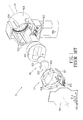
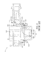
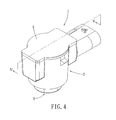
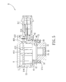
- the ultrasonic sensor device 1 comprises a housing 2, a transducer 3, a securing unit 4, a circuit board 5, and a sealing cap 6.
- the housing 2 is in a substantially cylindrical shape, and includes an enclosing portion 21, a resilient shock-absorbing ring 22, and an outer connecting pin set 23 disposed in the enclosing portion 21.
- the outer connecting pin set includes three outer connecting pins 231 to 233.
- the enclosing portion 21 is formed with a connecting tube portion 211 on an outer surface, three slide grooves 212 on an inner surface, a first opening 213, a second opening 214 that is opposite to the first opening 213 and that is in spatial communication with the first opening 213, and four positioning blocks 216. It is noted that various numbers of the slide grooves 212 and the positioning blocks 216 may be employed in other embodiments of this invention.
- the resilient shock-absorbing ring 22 is made of, for example, rubber material, and is disposed at the second opening 214 of the enclosing portion 21 to contact and surround the transducer 3.
- Each of the outer connecting pins 231 to 233 of the outer connecting pin set 23 has one end extending toward the first opening 213 for electrical connection with the circuit board 5, and another end extending into the connecting tube portion 211 for electrical connection with an external control circuit (not shown in the Figures).
- each of the outer connecting pins 231 to 233 serves, respectively, as a ground pin, a signal transmitting pin, and a power transmitting pin.
- the positioning of the outer connecting pins 231 to 233 can be arranged as shown in Figure 7 (each pair of adjacent outer connecting pins are equally spaced apart), although various modifications can be employed in other embodiments of this invention.
- the transducer 3 is secured to the enclosing portion 21 at the second opening 214, and includes a metal shell 31, a piezoelectric member 32 and a cushioning member 33.
- the piezoelectric member 32 is disposed in the shell 31, and is configured to generate and emit ultrasonic wave which is for measuring distance with nearby objects, and to receive the reflected ultrasonic wave for generating a sensing signal accordingly.
- the cushioning member 33 is made of a foam material, and is disposed in the receiving base 31 to press against the piezoelectric member 32 for absorbing external shock.
- the securing unit 4 includes a securing component 41, a resilient shock-absorbing component 42, and an inner connecting pin set 43 disposed on the securing component 41 and electrically connected to the transducer 3.
- the inner connecting pin set includes two inner connecting pins 431 and 432.
- the securing component 41 is disposed secures the transducer 3 to the enclosing portion 21, and includes three protruding blocks 411 and two securing ribs 412. Each of the three protruding blocks 411 is configured to engage slidably a respective one of the slide grooves 212. Each of the securing ribs 412 is registered with one of the protruding blocks 411, and extends toward the first opening 213 of the enclosing portion 21. It is noted that various numbers of the protruding blocks 411 and the securing ribs 412 may be employed in other embodiments of this invention.
- the resilient shock-absorbing component 42 is disposed at the securing component 41 for abutting against the shell 31 of the transducer 3 and the resilient shock-absorbing ring 22, thereby securing the transducer 3 to the enclosing portion 21.
- Each of the inner connecting pins 431 and 432 has one end electrically connected to the circuit board 5.
- Each of the inner connecting pins 431 and 432 further has another end that is electrically connected to the piezoelectric member 32 and the shell 31 of the transducer 3, respectively. As a result, the sensing signal generated by the piezoelectric member 32 can be transmitted to the circuit board 5 for processing.
- the circuit board 5 is disposed on the positioning blocks 216 in the enclosing portion 21 adjacent to the first opening 213, and is connected electrically to ends of the inner and outer connecting pins 231 to 233, 431 and 432. Accordingly, the transducer 3 is electrically connected to the external control circuit via the circuit board 5.
- the sealing cap 6 is disposed to cover the first opening 213 of the enclosing portion 21, and has an inner cap surface that abuts against the securing ribs 412 of the securing unit 4. Such abutment is able to prevent movement of the transducer 3 and the securing unit 4 relative to the enclosing portion 21.
- step S1 the transducer 3 is assembled to the housing 2 at the second opening 214. Specifically, the transducer 3 is disposed in the enclosing portion 21 through the first opening 213 (see Figure 9 ), and a part of the transducer 3 projects out of the enclosing portion 21 through the second opening 214 (see Figure 10 ).
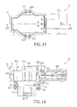
- step S2 the securing unit 4 is disposed in the enclosing portion 21, thereby securing the transducer 3 to the enclosing portion 21. Specifically, this is done by registering the protruding blocks 411 and the securing ribs 412 of the securing unit 4 with the slide grooves 212 at the first opening 213, and sliding the securing unit 4 into the enclosing portion 21 toward the second opening 214 until the resilient shock-absorbing component 42 abuts against the shell 31 of the transducer 3 and the resilient shock-absorbing ring 22 (see Figure 12 ).
- the inner connecting pins 431 and 432 are also connected to the transducer 3 in this step.
- step S3 the circuit board 5 is disposed in the enclosing portion 21 on the positioning blocks 216 adjacent to the first opening 213, and is connected electrically to the inner connecting pin set 23 of the securing unit 4 and the outer connecting pin set 43 of the housing 2 (see Figure 14 ).
- step S4 the sealing cap 6 is disposed at the housing 2 to cover the first opening 213 of the enclosing portion 21, in a manner that an inner cap surface of the sealing cap 6 abuts against the securing ribs 412 of the securing unit 4. This may further secure the securing unit 4 and the transducer 3 inside the enclosing portion 21.
- the sealing cap 6 is connected to the housing 2 via one of ultrasonic welding and laser welding. The assembling method is subsequently completed.
- the ultrasonic sensor device 1 of this invention is provided with the securing ribs 412, such that the securing of the transducer 3 and the securing unit 4 can be achieved without needing to employ an adhesive material. Moreover, external shock resistance of the ultrasonic sensor device 1 is also enhanced, thereby eliminating the need for a liquid sealing component. As a result, the ultrasonic sensor device 1 can be produced in a more time efficient manner and with a relatively higher production yield.
Landscapes
- Physics & Mathematics (AREA)
- Engineering & Computer Science (AREA)
- Acoustics & Sound (AREA)
- Multimedia (AREA)
- General Physics & Mathematics (AREA)
- Transducers For Ultrasonic Waves (AREA)
- Measurement Of Velocity Or Position Using Acoustic Or Ultrasonic Waves (AREA)
Applications Claiming Priority (2)
| Application Number | Priority Date | Filing Date | Title |
|---|---|---|---|
| TW101219434U TWM446121U (zh) | 2012-10-08 | 2012-10-08 | 嵌合式超聲波傳感器裝置 |
| TW101137107A TW201415057A (zh) | 2012-10-08 | 2012-10-08 | 嵌合式超聲波傳感器裝置及其組裝方法 |
Publications (1)
| Publication Number | Publication Date |
|---|---|
| EP2717256A2 true EP2717256A2 (de) | 2014-04-09 |
Family
ID=47998262
Family Applications (1)
| Application Number | Title | Priority Date | Filing Date |
|---|---|---|---|
| EP13161179.0A Withdrawn EP2717256A2 (de) | 2012-10-08 | 2013-03-26 | Ultraschall-Sensorvorrichtung und Aufbauverfahren dafür |
Country Status (3)
| Country | Link |
|---|---|
| US (1) | US20140096609A1 (de) |
| EP (1) | EP2717256A2 (de) |
| JP (1) | JP5640125B2 (de) |
Families Citing this family (5)
| Publication number | Priority date | Publication date | Assignee | Title |
|---|---|---|---|---|
| FR3040213B1 (fr) * | 2015-08-18 | 2017-09-15 | Continental Automotive France | Procede de fabrication d'un capteur de mesure pour vehicule automobile |
| FR3040214B1 (fr) * | 2015-08-18 | 2017-09-15 | Continental Automotive France | Capteur de mesure a support de composant electrique pour vehicule automobile |
| JP6641789B2 (ja) * | 2015-08-27 | 2020-02-05 | 株式会社デンソー | 空気流量測定装置 |
| DE102018102784B4 (de) | 2018-02-08 | 2023-09-21 | Valeo Schalter Und Sensoren Gmbh | Verfahren und Vorrichtung zum Verbinden zweier Bauteile, sowie deren Verwendung |
| TWI705588B (zh) * | 2019-06-12 | 2020-09-21 | 千竣科技有限公司 | 超聲波偵測設備 |
Family Cites Families (6)
| Publication number | Priority date | Publication date | Assignee | Title |
|---|---|---|---|---|
| JP3991936B2 (ja) * | 2003-06-30 | 2007-10-17 | 松下電工株式会社 | 超音波送受波器 |
| DE102005025147B4 (de) * | 2005-06-01 | 2014-11-06 | Continental Automotive Gmbh | Kraftstoffinjektor mit Gehäuse, sowie Verfahren zum Fertigstellen und Beschriften des Gehäuses |
| KR100843403B1 (ko) * | 2006-12-19 | 2008-07-03 | 삼성전기주식회사 | 렌즈 이송장치 |
| JP5195572B2 (ja) * | 2009-03-26 | 2013-05-08 | 株式会社デンソー | 超音波センサ |
| JP5075171B2 (ja) * | 2009-09-02 | 2012-11-14 | パナソニック株式会社 | 超音波センサ |
| JP2011239089A (ja) * | 2010-05-07 | 2011-11-24 | Denso Corp | 超音波センサ、その調整方法、及びその製造方法 |
-
2013
- 2013-03-15 US US13/841,937 patent/US20140096609A1/en not_active Abandoned
- 2013-03-26 EP EP13161179.0A patent/EP2717256A2/de not_active Withdrawn
- 2013-09-02 JP JP2013180976A patent/JP5640125B2/ja not_active Expired - Fee Related
Non-Patent Citations (1)
| Title |
|---|
| None |
Also Published As
| Publication number | Publication date |
|---|---|
| JP2014078931A (ja) | 2014-05-01 |
| US20140096609A1 (en) | 2014-04-10 |
| JP5640125B2 (ja) | 2014-12-10 |
Similar Documents
| Publication | Publication Date | Title |
|---|---|---|
| US9339846B2 (en) | Ultrasonic sensor assembly | |
| US20140096609A1 (en) | Ultrasonic sensor device and method for assembling the same | |
| US10288730B2 (en) | Ultrasonic sensor | |
| JP6443322B2 (ja) | 超音波センサ | |
| US11307305B2 (en) | Ultrasonic sensor | |
| EP2808694A2 (de) | Ultraschallwellenvorrichtung | |
| JP6780633B2 (ja) | 超音波センサ | |
| JP5075171B2 (ja) | 超音波センサ | |
| US20170122786A1 (en) | Ultrasonic transducer arrangement and ultrasonic water meter | |
| CN104246533B (zh) | 车辆用超声波传感器装置以及车辆用超声波传感器装置的组装方法 | |
| EP2631902A1 (de) | Ultraschallsensorsvorrichtung, Komponentenmodul davon, und Verfahren zur Herstellung der Ultraschallsensorsvorrichtung | |
| EP2879128B1 (de) | Ultraschallsensor und verfahren zu seiner herstellung | |
| US8981622B2 (en) | Ultrasonic sensor device | |
| CN102692623B (zh) | 超声波传感器 | |
| JP5814798B2 (ja) | 超音波送受波器 | |
| JP3179895U (ja) | 超音波センサーの組立モジュール | |
| WO2018164153A1 (ja) | 超音波センサ | |
| JP7118041B2 (ja) | 超音波送受信器 | |
| KR102121421B1 (ko) | 초음파 센서 조립체의 조립방법 | |
| KR102326056B1 (ko) | 차량용 감지센서 | |
| KR20130096594A (ko) | 센서 고정 장치 | |
| KR20160013683A (ko) | 차량용 감지센서 | |
| JP2013143589A (ja) | 超音波送受波器 | |
| KR102351065B1 (ko) | 초음파 센서용 센서셀 | |
| TW201415057A (zh) | 嵌合式超聲波傳感器裝置及其組裝方法 |
Legal Events
| Date | Code | Title | Description |
|---|---|---|---|
| PUAI | Public reference made under article 153(3) epc to a published international application that has entered the european phase |
Free format text: ORIGINAL CODE: 0009012 |
|
| AK | Designated contracting states |
Kind code of ref document: A2 Designated state(s): AL AT BE BG CH CY CZ DE DK EE ES FI FR GB GR HR HU IE IS IT LI LT LU LV MC MK MT NL NO PL PT RO RS SE SI SK SM TR |
|
| AX | Request for extension of the european patent |
Extension state: BA ME |
|
| STAA | Information on the status of an ep patent application or granted ep patent |
Free format text: STATUS: THE APPLICATION IS DEEMED TO BE WITHDRAWN |
|
| 18D | Application deemed to be withdrawn |
Effective date: 20151001 |