EP2716546A2 - Monumentenkomplex für einen Flugzeugheckbereich - Google Patents
Monumentenkomplex für einen Flugzeugheckbereich Download PDFInfo
- Publication number
- EP2716546A2 EP2716546A2 EP13199330.5A EP13199330A EP2716546A2 EP 2716546 A2 EP2716546 A2 EP 2716546A2 EP 13199330 A EP13199330 A EP 13199330A EP 2716546 A2 EP2716546 A2 EP 2716546A2
- Authority
- EP
- European Patent Office
- Prior art keywords
- contour
- aircraft
- aircraft according
- cabin
- toilet
- Prior art date
- Legal status (The legal status is an assumption and is not a legal conclusion. Google has not performed a legal analysis and makes no representation as to the accuracy of the status listed.)
- Granted
Links
Images

Classifications
-
- B—PERFORMING OPERATIONS; TRANSPORTING
- B64—AIRCRAFT; AVIATION; COSMONAUTICS
- B64D—EQUIPMENT FOR FITTING IN OR TO AIRCRAFT; FLIGHT SUITS; PARACHUTES; ARRANGEMENT OR MOUNTING OF POWER PLANTS OR PROPULSION TRANSMISSIONS IN AIRCRAFT
- B64D11/00—Passenger or crew accommodation; Flight-deck installations not otherwise provided for
- B64D11/02—Toilet fittings
-
- B—PERFORMING OPERATIONS; TRANSPORTING
- B64—AIRCRAFT; AVIATION; COSMONAUTICS
- B64C—AEROPLANES; HELICOPTERS
- B64C1/00—Fuselages; Constructional features common to fuselages, wings, stabilising surfaces or the like
- B64C1/14—Windows; Doors; Hatch covers or access panels; Surrounding frame structures; Canopies; Windscreens accessories therefor, e.g. pressure sensors, water deflectors, hinges, seals, handles, latches, windscreen wipers
- B64C1/1407—Doors; surrounding frames
- B64C1/1423—Passenger doors
-
- B—PERFORMING OPERATIONS; TRANSPORTING
- B64—AIRCRAFT; AVIATION; COSMONAUTICS
- B64D—EQUIPMENT FOR FITTING IN OR TO AIRCRAFT; FLIGHT SUITS; PARACHUTES; ARRANGEMENT OR MOUNTING OF POWER PLANTS OR PROPULSION TRANSMISSIONS IN AIRCRAFT
- B64D11/00—Passenger or crew accommodation; Flight-deck installations not otherwise provided for
- B64D11/04—Galleys
-
- B—PERFORMING OPERATIONS; TRANSPORTING
- B64—AIRCRAFT; AVIATION; COSMONAUTICS
- B64D—EQUIPMENT FOR FITTING IN OR TO AIRCRAFT; FLIGHT SUITS; PARACHUTES; ARRANGEMENT OR MOUNTING OF POWER PLANTS OR PROPULSION TRANSMISSIONS IN AIRCRAFT
- B64D11/00—Passenger or crew accommodation; Flight-deck installations not otherwise provided for
- B64D2011/0046—Modular or preassembled units for creating cabin interior structures
Definitions
- the invention relates to the equipment of aircraft cabins. More particularly, the invention relates to an aircraft having a complex of monuments for attachment to a rear of a cabin of the aircraft.
- monuments such as on-board toilet monuments (Lavatories) or kitchen monuments (galleys) have three or four flat walls.
- WO 2004/076279 A2 describes an aircraft toilet assembly with several toilets for the rear of an aircraft cabin. It is provided an entrance area, which is located in front of the urinal in the rear area and behind the sink in the front of the arrangement.
- CA 2 640 123 A1 and EP 1 986 914 A1 describe a galley arrangement for an aircraft having four flat walls.
- an aircraft is provided with a monument complex for attachment to a rear area of a cabin of the aircraft, which has a system component, a rear contour and an entry area.
- the system component is a component selected from the group consisting of washstand and base cabinet with system technology contained therein.
- the entry area is arranged in front of the system component and the rear contour of the monument complex is at least partially adapted to a contour of the rear area of the cabin.
- the fact that the entry area is arranged "in front of" the system component means that the entrance area in the direction of flight is in front of the system component when the monument complex is installed in the cabin of the aircraft.
- the passenger enters the entrance area of the monument complex from the car and can then move further in the direction of the system component.
- the rear contour of the monument complex is at least partially adapted to the contour of the rear area of the cabin means that it is in the Rear side of the monument complex is not a flat wall, since the contour of the rear area of the cabin is usually a three-dimensionally curved surface.
- the rear contour of the cabin is defined by a pressure bulkhead.
- the back contour of the car defines a space, wherein the system component is at least partially disposed in the defined space.
- the monument complex and at least some of the parts installed therein projects at least partially or completely into the space defined by the rear contour.
- the monument complex has a second system component, which is a toilet.
- a second system component which is a toilet.
- other system components such as a second or third toilet and / or several other washbasins, may be provided.
- the rear contour is formed as a three-dimensionally curved surface.
- the monument complex has two on-board toilet modules.
- the two on-board toilet modules can be designed separately or integrally.
- the monument complex can be made in several parts or in one piece.
- the monument complex has a kitchen module or a plurality of such kitchen modules.
- the complex of monuments can thus contain a galley and / or an on-board toilet complex.
- the monument complex has a first door to a first portion of the monument complex and a second door to a second portion of the monument complex, wherein the first door and the second door at an angle not equal to 180 degrees to each other.
- the monument complex has a partition wall for separating the two on-board toilet modules from each other, wherein the partition wall is arranged in the middle of the monument complex.
- the partition In the case of execution of the monument complex in the form of two separate on-board toilet modules, the partition is double-walled (so it is, for example, two separate partitions), the one partition belongs to an on-board toilet module and the other partition to the other on-board toilet module.
- the rear contour is formed as a continuous wall.
- This continuous wall can be stepped (such as in Fig. 2A shown) or curved two or even three-dimensional (as in Fig. 3 shown).
- the complex of monuments is in the form of two sub-modules which, when installed in the cabin of the aircraft, are introduced separately into the car. The sub-modules are then connected together in the cabin, if necessary.
- the cabin is a passenger cabin of a commercial aircraft.
- an aircraft is specified with a complex of monuments described above and below.
- the aircraft is, for example, a passenger aircraft (with or without a pressurized cabin) or else a helicopter or an airship (zeppelin).
- Fig. 1 shows a rear portion of a passenger cabin 108 of an aircraft.
- the arrow 109 symbolizes the direction of flight.
- a toilet complex is arranged, which has two toilets 101, 102. It is a main entrance door 104 is provided, which opens to the outside (ie, forward to the passenger cabin). The user enters the entrance area or entrance area 116 through this door 104.
- a wash basin 112 is arranged behind the entrance area 116.
- the two toilet modules with the toilets 101, 102 are provided.
- the modules can be opened via the folding doors 114 and 115 respectively.
- the complex is arranged directly in front of the rear pressure bulkhead 111, which is usually made concave towards the cabin side. In this meadow, there is a "dead” unused space. This room can not be used for cabin functions.
- the "dead" space 110 defined by the curved contour 107 of the pressure bulkhead 111 is not used by the toilet modules.
- the rear contour 103 of the modules is designed in the form of a flat wall.
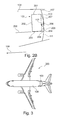
- Fig. 2A shows a monument complex 100 according to an embodiment of the invention, which is arranged in the rear area of the passenger cabin 108.
- the monument complex 100 has two individual toilet modules, each with a toilet 101, 102.
- the two toilet modules abut each other and are separated by the partition 106 from each other. It can also be provided two such partitions 106, one for each of the two modules.
- a continuous or two-part vanity is provided (see reference numerals 112, 113), each with a sink for the left and the right toilet module.
- the partition wall 106 has a corresponding recess through which the wash basin extends.
- the two doors enclose an angle not equal to 180 degrees to each other. In the case of the embodiment of Fig. 2A the angle is about 120 degrees. The angle could also be about 90 degrees.
- This angle provides additional space in the passenger cabin.
- the user Through the left door 104, the user enters the upper entrance area 116 and through the right door 105 the user enters the right ("lower") entrance area 116 of the second toilet module.
- the rear contour 103 of the monument complex is adapted to the shape of the rear region of the cabin, in particular to the shape of the pressure bulkhead 111. This is achieved in that the or the washbasins 112, 113 partially disposed in the space defined by the curvature of the pressure bulkhead are. As a result, additional space in the direction of flight 109 is obtained.
- Fig. 2A shows how out of the Fig. 1 Lavatory shown by the enlargement in the first place a conveniently usable lavatory is provided without this seats would have to be omitted.
- the cultivation of box-shaped extensions means a small extra effort in the production, the gain of a few inches of cabin length, however, a great benefit.
- a key aspect of the invention is that the pressure bulkhead facing wall of the monument complex (here the Lavatory) is designed so that there is an optimized use of space. Instead of a flat wall of the pressure bulkhead contour approximated contour of the wall is installed. Thus, through the newly won room, an additional sink can be provided, as in Fig. 2A and 2 B shown. Furthermore, the usable inlet area increases.
- a further improvement can be achieved by a wall designed as an offset (three-dimensionally curved surface) of the pressure bulkhead, as shown in FIG Fig. 3 you can see.
- Fig. 2B shows a side view of the area of Fig. 2A
- the monument complex 100 has a ceiling 201, a front wall 202, a bottom 203 and a plurality of rear wall segments 204, 205, 206, 207.
- the various segments of the rear wall may be integrally connected.
- the monument complex is arranged on the cabin floor 208.
- the rear wall segments 204, 205 include a free space 209, in which system lines can be located, which connect the system components of the monument complex to the aircraft supply.
- the first segment 204 is vertical and the second segment 205 is arranged horizontally.
- Fig. 3 shows an aircraft 300 with a arranged in the rear area Monument complex 100 with a two-dimensional or three-dimensional curved shaped rear wall.
Landscapes
- Engineering & Computer Science (AREA)
- Aviation & Aerospace Engineering (AREA)
- Mechanical Engineering (AREA)
- Sanitary Device For Flush Toilet (AREA)
- Residential Or Office Buildings (AREA)
- Body Structure For Vehicles (AREA)
Abstract
Description
- Die Erfindung betrifft die Ausstattung von Flugzeugkabinen. Insbesondere betrifft die Erfindung ein Luftfahrzeug mit einem Monumentenkomplex zur Anbringung in einem Heckbereich einer Kabine des Luftfahrzeugs.
- In heutigen Flugzeugen besitzen Monumente, wie beispielsweise Bordtoilettenmonumente (Lavatories) oder Küchenmonumente (Galleys), drei oder vier ebene Wände.
-
WO 2004/076279 A2 beschreibt eine Flugzeugtoilettenanordnung mit mehreren Toiletten für den Heckbereich einer Flugzeugkabine. Es ist ein Eingangsbereich vorgesehen, der vor den Pissoirs im Heckbereich und hinter den Waschbecken im Vorderbereich der Anordnung angeordnet ist. -
CA 2 640 123 A1 undEP 1 986 914 A1 beschreiben eine Galleyanordnung für ein Flugzeug, die vier ebene Wände aufweist. - Es ist eine Aufgabe der Erfindung, eine Anordnung von Systemkomponenten in einer Passagierkabine eines Flugzeugs anzugeben, welche möglichst wenig Kabinenraum einnimmt.
- Es ist ein Luftfahrzeug mit einem Monumentenkomplex zur Anbringung in einem Heckbereich einer Kabine des Luftfahrzeugs gemäß den Merkmalen des unabhängigen Anspruchs angegeben. Weiterbildungen der Erfindung ergeben sich aus den Unteransprüchen.
- Gemäß einem Ausführungsbeispiel der Erfindung ist ein Luftfahrzeug mit einem Monumentenkomplex zur Anbringung in einem Heckbereich einer Kabine des Luftfahrzeugs angegeben, welcher eine Systemkomponente, eine rückseitige Kontur und einen Eintrittsbereich aufweist. Bei der Systemkomponente handelt es sich um eine Komponente ausgewählt aus der Gruppe bestehend aus Waschtisch und Unterschrank mit darin enthaltener Systemtechnik. Der Eintrittsbereich ist vor der Systemkomponente angeordnet und die rückseitige Kontur des Monumentenkomplexes ist zumindest teilweise an eine Kontur des Heckbereichs der Kabine angepasst.
- Dass der Eintrittsbereich "vor" der Systemkomponente angeordnet ist, bedeutet, dass sich der Eintrittsbereich in Flugrichtung vor der Systemkomponente befindet, wenn der Monumentenkomplex in der Kabine des Luftfahrzeugs eingebaut ist. Mit anderen Worten betritt der Passagier von der Kabine den Eintrittsbereich des Monumentenkomplexes und kann sich dann weiter bewegen in Richtung auf die Systemkomponente.
- Dass die rückseitige Kontur des Monumentenkomplexes zumindest teilweise an die Kontur des Heckbereichs der Kabine angepasst ist, bedeutet, dass es sich bei der Rückseite des Monumentenkomplexes um keine ebene Wand handelt, da die Kontur des Heckbereiches der Kabine im Regelfall eine dreidimensional gekrümmte Fläche darstellt.
- Gemäß einem weiteren Ausführungsbeispiel der Erfindung ist die rückseitige Kontur der Kabine durch ein Druckschott vorgegeben.
- Gemäß einem weiteren Ausführungsbeispiel der Erfindung definiert die rückseitige Kontur der Kabine einen Raum, wobei die Systemkomponente zumindest teilweise in dem definierten Raum angeordnet ist.
- Gemäß einem weiteren Ausführungsbeispiel der Erfindung ragt der Monumentenkomplex und zumindest einige der darin verbauten Teile, wie beispielsweise ein Waschtisch samt Unterschrank und darin enthaltene Systemtechnik, zumindest teilweise oder gänzlich in den durch die rückseitige Kontur definierten Raum hin.
- Gemäß einem weiteren Ausführungsbeispiel der Erfindung weist der Monumentenkomplex eine zweite Systemkomponente auf, bei der es sich um eine Toilette handelt. Natürlich können noch weitere Systemkomponenten, wie beispielsweise eine zweite oder dritte Toilette und/oder mehrere weitere Waschtische, vorgesehen sein.
- Gemäß einem weiteren Ausführungsbeispiel der Erfindung ist die rückseitige Kontur als dreidimensional gekrümmte Fläche ausgebildet.
- Gemäß einem weiteren Ausführungsbeispiel der Erfindung weist der Monumentenkomplex zwei Bordtoilettenmodule auf.
- Die beiden Bordtoilettenmodule können getrennt voneinander oder integral ausgeführt sein. In anderen Worten kann der Monumentenkomplex mehrteilig ausgeführt sein oder einteilig.
- Gemäß einem weiteren Ausführungsbeispiel der Erfindung weist der Monumentenkomplex ein Küchenmodul oder mehrere solche Küchenmodule auf.
- Der Monumentenkomplex kann also eine Bordküche und/oder einen Bordtoilettenkomplex enthalten.
- Gemäß einem weiteren Ausführungsbeispiel der Erfindung weist der Monumentenkomplex eine erste Tür zu einem ersten Teilbereich des Monumentenkomplexes und eine zweite Tür zu einem zweiten Teilbereich des Monumentenkomplexes auf, wobei die erste Tür und die zweite Tür einen Winkel ungleich 180 Grad zueinander einschließen.
- Auf diese Weise kann wertvoller Raum in der Passagierkabine eingespart werden, da die beiden Türen nicht senkrecht zur Flugzeuglängsachse angeordnet sind, sondern schräg zur Längsachse.
- Gemäß einem weiteren Ausführungsbeispiel der Erfindung weist der Monumentenkomplex eine Trennwand zum Abtrennen der beiden Bordtoilettenmodule voneinander auf, wobei die Trennwand in der Mitte des Monumentenkomplexes angeordnet ist.
- Im Falle der Ausführung des Monumentenkomplexes in Form von zwei getrennten Bordtoilettenmodulen ist die Trennwand doppelwandig ausgeführt (es handelt sich also beispielsweise um zwei getrennte Trennwände), wobei die eine Trennwand zum einen Bordtoilettenmodul und die andere Trennwand zu dem anderen Bordtoilettenmodul gehört.
- Gemäß einem weiteren Ausführungsbeispiel der Erfindung ist die rückseitige Kontur als zusammenhängende Wand ausgebildet. Diese zusammenhängende Wand kann stufenförmig (wie beispielsweise in
Fig. 2A dargestellt) ausgebildet oder zwei- oder gar dreidimensional gekrümmt sein (wie inFig. 3 dargestellt). - Gemäß einem weiteren Ausführungsbeispiel der Erfindung ist der Monumentenkomplex in Form von zwei Teilmodulen ausgeführt, die bei Installation in der Kabine des Luftfahrzeugs getrennt voneinander in die Kabine eingeführt werden. Die Teilmodule werden dann erst in der Kabine miteinander verbunden, falls überhaupt erforderlich.
- Gemäß einem weiteren Ausführungsbeispiel der Erfindung handelt es sich bei der Kabine um eine Passagierkabine eines Verkehrsflugzeugs.
- Gemäß einem weiteren Ausführungsbeispiel der Erfindung ist ein Luftfahrzeug mit einem oben und im Folgenden beschriebenen Monumentenkomplex angegeben.
- Gemäß einem weiteren Ausführungsbeispiel der Erfindung ist die Verwendung eines oben und im Folgenden beschriebenen Monumentenkomplexes in einem Luftfahrzeug angegeben.
- Bei dem Luftfahrzeug handelt es sich beispielsweise um ein Passagierflugzeug (mit oder ohne Druckkabine) oder aber auch um einen Helikopter oder ein Luftschiff (Zeppelin).
- Im Folgenden werden mit Verweis auf die Figuren Ausführungsbeispiele der Erfindung beschrieben.
-
-
Fig. 1 zeigt eine Ansicht eines Heckbereichs einer Flugzeugkabine mit einem darin angeordneten Monumentenkomplex. -
Fig. 2A zeigt eine Ansicht eines Heckbereichs einer Flugzeugkabine gemäß einem Ausführungsbeispiel der Erfindung. -
Fig. 2B zeigt den Heckbereich derFig. 2A von der Seite ausgesehen. -
Fig. 3 zeigt ein Luftfahrzeug mit einem Monumentenkomplex gemäß einem Ausführungsbeispiel der Erfindung. - Die Darstellungen in den Figuren sind schematisch und nicht maßstäblich.
- In der folgenden Figurenbeschreibung werden für die gleichen oder ähnlichen Elemente die gleichen Bezugsziffern verwendet.
-
Fig. 1 zeigt einen Heckbereich einer Passagierkabine 108 eines Flugzeugs. Der Pfeil 109 symbolisiert die Flugrichtung. In dem Heckbereich ist ein Toilettenkomplex angeordnet, der zwei Toiletten 101, 102 aufweist. Es ist eine Haupteingangstür 104 vorgesehen, die nach außen (also nach vorne zur Passagierkabine hin) öffnet. Der Benutzer betritt durch diese Tür 104 den Eingangsbereich oder Eintrittsbereich 116. Hinter dem Eintrittsbereich 116 ist ein Waschtisch 112 angeordnet. - Links und rechts von dem Eintrittsbereich 116 sind die beiden Toilettenmodule mit den Toiletten 101, 102 vorgesehen. Die Module lassen sich über die Falttüren 114 bzw. 115 öffnen.
- Der Komplex ist direkt vor dem hinteren Druckschott 111 angeordnet, welches üblicherweise zur Kabinenseite hin konkav ausgeführt ist. Auf diese Wiese entsteht dort ein "toter" ungenutzter Raum. Dieser Raum kann nicht für Kabinenfunktionen genutzt werden.
- Der durch die gewölbte Kontur 107 des Druckschotts 111 definierte "tote" Raum 110 wird von den Toilettenmodulen nicht genutzt. Die rückseitige Kontur 103 der Module ist in Form einer ebenen Wand ausgeführt.
-
Fig. 2A zeigt einen Monumentenkomplex 100 gemäß einem Ausführungsbeispiel der Erfindung, der im Heckbereich der Passagierkabine 108 angeordnet ist. - Der Monumentenkomplex 100 weist zwei einzelne Toilettenmodule mit je einer Toilette 101, 102 auf. Die beiden Toilettenmodule stoßen aneinander an und sind über die Trennwand 106 voneinander getrennt. Es können auch zwei solche Trennwände 106 vorgesehen sein, jeweils eine für eines der beiden Module.
- Weiterhin ist ein zusammenhängender oder zweigeteilter Waschtisch vorgesehen (siehe Bezugszeichen 112, 113) mit jeweils einem Waschbecken für das linke und das rechte Toilettenmodul.
- Im Falle eines eingeteilten Waschtisches weist die Trennwand 106 eine entsprechende Aussparung auf, durch welche der Waschtisch verläuft.
- Es sind zwei Türen 104, 105 vorgesehen, eine für das linke Modul mit der Toilette 101 und eine für das rechte Modul mit der Toilette 102. Die beiden Türen schließen einen Winkel ungleich 180 Grad zueinander ein. Im Falle des Ausführungsbeispiels der
Fig. 2A beträgt der Winkel in etwa 120 Grad. Der Winkel könnte aber auch etwa 90 Grad betragen. - Durch diesen Winkel wird zusätzlicher Platz in der Passagierkabine gewonnen. Durch die linke Tür 104 gelangt der Benutzer in den oberen Eintrittsbereich 116 und durch die rechte Tür 105 gelangt der Benutzer in den rechten ("unteren") Eintrittsbereich 116 des zweiten Toilettenmoduls.
- Die rückseitige Kontur 103 des Monumentenkomplexes ist an die Form des Heckbereichs der Kabine angepasst, insbesondere also an die Form des Druckschotts 111. Dies wird dadurch erreicht, dass der bzw. die Waschtische 112, 113 teilweise in dem durch die Krümmung des Druckschotts definierten Raum angeordnet sind. Hierdurch wird zusätzlicher Platz in Flugrichtung 109 gewonnen.
- Wie in
Fig. 1 zu sehen, ist der Toilettenkomplex (Lavatory) in X-Länge (also in Flugrichtung 109) minimiert. Aufgrund dieser Ausführungsform (nur ein Waschtisch mit verengtem Zugang) ist keine bequeme Nutzung möglich. Eine klassische Vergrößerung der Lavatory in Flugrichtung 109 würde den Verlust von wertvollen Sitzplätzen zur Folge haben. - Wie in
Fig. 2A zu sehen, wird das Gesamtvolumen der Lavatory vergrößert, ohne dass der Monumentenkomplex in Flugrichtung 109 ausgedehnt wird. Dadurch wird der bewegungsfreie Raum innerhalb der Lavatory vergrößert. Das Beispiel inFig. 2A zeigt, wie aus der inFig. 1 gezeigten Lavatory durch die Vergrößerung überhaupt erst eine bequem nutzbare Lavatory bereitgestellt ist, ohne dass hierdurch Sitzplätze entfallen müssten. Beispielsweise ist der Waschtisch 112, 113 sowie der Unterschrank mit der enthaltenen Systemtechnik in den neugewonnenen Raum (zumindest teilweise) verlegt. Der Anbau von kastenförmigen Erweiterungen bedeutet in der Herstellung einen geringen Zusatzaufwand, der Gewinn von einigen Zoll Kabinenlänge dagegen einen großen Nutzen. - Es handelt sich also um eine Lavatory mit Raumausnutzung in der Bulkhead-Wölbung.
- Ein Kernaspekt der Erfindung besteht darin, dass die dem Druckschott zugewandte Wand des Monumentenkomplexes (hier der Lavatory) so gestaltet wird, dass sich eine optimierte Raumausnutzung ergibt. Anstelle einer ebenen Wand wird eine der Druckschottkontur angenäherte Kontur der Wand verbaut. So kann durch den neu gewonnenen Raum ein zusätzliches Waschbecken vorgesehen sein, wie in
Fig. 2A und2B gezeigt. Weiterhin vergrößert sich der nutzbare Eintrittsbereich. - Dabei kann auf gleiche Materialien und Bauweisen zurückgegriffen werden, welches üblicherweise für Monumentrückwände verwendet werden.
- Eine weitere Verbesserung kann durch eine als Offset (dreidimensional gekrümmte Fläche) des Druckschotts ausgeführte Wand erzielt werden, wie sie in
Fig. 3 zu sehen ist. -
Fig. 2B zeigt eine Seitenansicht des Bereichs derFig. 2A . Der Monumentenkomplex 100 weist eine Decke 201, eine Vorderwand 202, einen Boden 203 und mehrere Rückwandsegmente 204, 205, 206, 207 auf. - Die verschiedenen Segmente der Rückwand können integral verbunden sein. Der Monumentenkomplex ist auf dem Kabinenboden 208 angeordnet.
- Wie in
Fig. 2B zu erkennen, schließen die Rückwandsegmente 204, 205 einen Freiraum 209 ein, in dem sich Systemleitungen befinden können, die die Systemkomponenten des Monumentenkomplexes an die Flugzeugversorgung anschließen. Hierfür ist das erste Segment 204 vertikal und das zweite Segment 205 horizontal angeordnet. -
Fig. 3 zeigt ein Luftfahrzeug 300 mit einem im Heckbereich angeordneten Monumentenkomplex 100 mit einer zweidimensional oder dreidimensional gekrümmt geformten Rückwand. - Ergänzend sei darauf hingewiesen, dass "umfassend" und "aufweisend" keine anderen Elemente oder Schritte ausschließt und "eine" oder "ein" keine Vielzahl ausschließt. Ferner sei darauf hingewiesen, dass Merkmale oder Schritte, die mit Verweis auf eines der obigen Ausführungsbeispiele beschrieben worden sind, auch in Kombination mit anderen Merkmalen oder Schritten anderer oben beschriebener Ausführungsbeispiele verwendet werden können. Bezugszeichen in den Ansprüchen sind nicht als Einschränkungen anzusehen.
Claims (13)
- Luftfahrzeug mit einem Monumentenkomplex, der in einem Heckbereich einer Kabine eines Luftfahrzeugs angebracht ist, der Monumentenkomplex (100) aufweisend:eine Systemkomponente (112, 113);ein Toilettenmodul mit einer Toilette (101, 102);eine rückseitige Kontur (103);einen Eintrittsbereich (116);wobei es sich bei der Systemkomponente (112, 113) um einen Waschtisch handelt;wobei der Eintrittsbereich (116) in Flugrichtung vor der Systemkomponente (112, 113) angeordnet ist; undwobei die rückseitige Kontur (103) zumindest teilweise an eine Kontur (107) des Heckbereichs der Kabine angepasst ist und die Kontur (107) einen Raum definiert, in dem die Systemkomponente (112, 113) zumindest teilweise angeordnet ist.
- Luftfahrzeug nach Anspruch 1,
wobei die rückseitige Kontur (103) zumindest teilweise an eine dreidimensional gekrümmte Kontur (107) eines Druckschotts im Heckbereich der Kabine angepasst ist und die Kontur (107) des Druckschotts einen Raum definiert, in dem die Systemkomponente (112, 113) zumindest teilweise angeordnet ist. - Luftfahrzeug nach Anspruch 1 oder 2,
wobei es sich bei der Systemkomponente (112, 113) um einen Waschtisch mit einem Waschbecken für das Toilettenmodul handelt. - Luftfahrzeug nach einem der vorhergehenden Ansprüche,
wobei die rückseitige Kontur (103) als dreidimensional gekrümmte Fläche ausgebildet ist. - Luftfahrzeug nach einem der vorhergehenden Ansprüche,
wobei der Monumentenkomplex (100) zwei Toilettenmodule mit jeweils einer Toilette (101, 102) und einem Waschbecken aufweist. - Luftfahrzeug nach einem der vorhergehenden Ansprüche,
wobei der Monumentenkomplex (100) ein Küchenmodul aufweist. - Luftfahrzeug nach einem der vorhergehenden Ansprüche,
wobei der Monumentenkomplex und darin verbaute Teile, wie beispielsweise der Waschtisch samt Unterschrank und darin enthaltene Systemtechnik zumindest teilweise oder gänzlich in den durch die rückseitige Kontur (103) definierten Raum hineinragt. - Luftfahrzeug nach einem der vorhergehenden Ansprüche, weiterhin aufweisend:eine erste Tür (104) zu einem ersten Teilbereich des Monumentenkomplexes (100);eine zweite Tür (105) zu einem zweiten Teilbereich des Monumentenkomplexes (100);wobei die erste Tür und die zweite Tür einen Winkel ungleich 180 Grad einschließen.
- Luftfahrzeug nach Anspruch 8,
wobei die erste Tür (104) eine Tür für das erste Toilettenmodul ist;
wobei die zweite Tür (105) eine Tür für das zweite Toilettenmodul ist. - Luftfahrzeug nach einem der Ansprüche 5 bis 9, weiterhin aufweisend:eine Trennwand (106) zum Abtrennen der beiden Toilettenmodule voneinander;wobei die Trennwand (106) in der Mitte des Monumentenkomplexes (100) angeordnet ist.
- Luftfahrzeug nach einem der vorhergehenden Ansprüche,
wobei die rückseitige Kontur (103) als zusammenhängende Wand ausgebildet ist. - Luftfahrzeug nach einem der vorhergehenden Ansprüche,
ausgeführt in Form von zwei Teilmodulen, die bei Installation in der Kabine getrennt voneinander in die Kabine eingeführt werden. - Luftfahrzeug nach einem der vorhergehenden Ansprüche,
wobei es sich bei der Kabine um eine Passagierkabine handelt.
Applications Claiming Priority (3)
| Application Number | Priority Date | Filing Date | Title |
|---|---|---|---|
| US17202309P | 2009-04-23 | 2009-04-23 | |
| DE102009018690A DE102009018690A1 (de) | 2009-04-23 | 2009-04-23 | Monumentenkomplex für einen Flugzeugheckbereich |
| EP10707050.0A EP2421756B1 (de) | 2009-04-23 | 2010-03-09 | Monumentenkomplex für einen flugzeugheckbereich |
Related Parent Applications (2)
| Application Number | Title | Priority Date | Filing Date |
|---|---|---|---|
| EP10707050.0A Division EP2421756B1 (de) | 2009-04-23 | 2010-03-09 | Monumentenkomplex für einen flugzeugheckbereich |
| EP10707050.0A Division-Into EP2421756B1 (de) | 2009-04-23 | 2010-03-09 | Monumentenkomplex für einen flugzeugheckbereich |
Publications (3)
| Publication Number | Publication Date |
|---|---|
| EP2716546A2 true EP2716546A2 (de) | 2014-04-09 |
| EP2716546A3 EP2716546A3 (de) | 2014-06-25 |
| EP2716546B1 EP2716546B1 (de) | 2018-06-13 |
Family
ID=42779694
Family Applications (2)
| Application Number | Title | Priority Date | Filing Date |
|---|---|---|---|
| EP13199330.5A Active EP2716546B1 (de) | 2009-04-23 | 2010-03-09 | Monumentenkomplex für einen Flugzeugheckbereich |
| EP10707050.0A Active EP2421756B1 (de) | 2009-04-23 | 2010-03-09 | Monumentenkomplex für einen flugzeugheckbereich |
Family Applications After (1)
| Application Number | Title | Priority Date | Filing Date |
|---|---|---|---|
| EP10707050.0A Active EP2421756B1 (de) | 2009-04-23 | 2010-03-09 | Monumentenkomplex für einen flugzeugheckbereich |
Country Status (5)
| Country | Link |
|---|---|
| US (2) | US8925862B2 (de) |
| EP (2) | EP2716546B1 (de) |
| CN (1) | CN102438902B (de) |
| DE (1) | DE102009018690A1 (de) |
| WO (1) | WO2010121862A1 (de) |
Families Citing this family (28)
| Publication number | Priority date | Publication date | Assignee | Title |
|---|---|---|---|---|
| CN102762455B (zh) * | 2010-02-19 | 2016-05-18 | 空中客车德国运营有限责任公司 | 用于交通工具的盥洗室装置 |
| US8590838B2 (en) | 2010-04-20 | 2013-11-26 | Be Intellectual Property, Inc. | Aircraft interior lavatory |
| DE102011010913A1 (de) | 2011-02-10 | 2012-08-16 | Airbus Operations Gmbh | Handtrocknungsvorrichtung und Waschtisch für ein Luftfahrzeug |
| CN103619707B (zh) * | 2011-02-18 | 2016-08-03 | 空中客车德国运营有限责任公司 | 模块化客舱部段、用于交通工具的客舱和具有客舱的交通工具 |
| USD749709S1 (en) | 2011-04-18 | 2016-02-16 | B/E Aerospace, Inc. | Aircraft interior lavatory |
| JP5825192B2 (ja) | 2012-05-11 | 2015-12-02 | 横浜ゴム株式会社 | 航空機用化粧室ユニットおよびその配置構造 |
| JP5849855B2 (ja) * | 2012-05-11 | 2016-02-03 | 横浜ゴム株式会社 | 航空機用化粧室ユニットおよびその配置構造 |
| JP5825240B2 (ja) * | 2012-10-12 | 2015-12-02 | 横浜ゴム株式会社 | 航空機用化粧室ユニット |
| US9108716B2 (en) * | 2012-11-06 | 2015-08-18 | The Boeing Company | Aircraft having a recessed cavity in an aft pressure bulkhead wall surface and a galley moved rearwardly into the recessed cavity increasing floor space in front of the galley |
| US9359076B2 (en) | 2013-02-11 | 2016-06-07 | B/E Aerospace, Inc. | Compact aircraft galley and lavatory arrangement and articulating lavatory partition for an aircraft |
| US9038945B2 (en) * | 2013-03-15 | 2015-05-26 | B/E Aerospace, Inc. | Integrated aircraft galley system |
| DE102013008290A1 (de) * | 2013-05-15 | 2014-11-20 | Airbus Operations Gmbh | Multifunktionales Flugzeugmonument und Flugzeugbereich |
| US9475583B2 (en) * | 2013-06-18 | 2016-10-25 | B/E Aerospace, Inc. | Location and support system for aircraft galley appliance inserts |
| EP2842870B1 (de) | 2013-08-30 | 2018-04-18 | Airbus Operations GmbH | Handbehandlungsvorrichtung |
| US10464677B2 (en) * | 2014-04-07 | 2019-11-05 | B/E Aerospace, Inc. | Aircraft modular lavatory system |
| US9862491B2 (en) * | 2014-04-07 | 2018-01-09 | B/E Aerospace, Inc. | Modular lavatory system optimized for narrow body commercial aircraft |
| USD871290S1 (en) * | 2014-10-13 | 2019-12-31 | Gulfstream Aerospace Corporation | Flight deck with surface ornamentation |
| USD766790S1 (en) * | 2014-10-14 | 2016-09-20 | Gulfstream Aerospace Corporation | Aircraft crew rest |
| US10583925B2 (en) * | 2015-02-12 | 2020-03-10 | The Boeing Company | Aft rest area assembly within an aircraft cabin |
| USD813132S1 (en) * | 2016-09-19 | 2018-03-20 | Iveco S.P.A. | Vehicle cockpit |
| USD812538S1 (en) * | 2017-02-08 | 2018-03-13 | Volvo Lastvagnar Ab | Vehicle interior |
| US10875435B1 (en) | 2017-03-30 | 2020-12-29 | Zoox, Inc. | Headrest with passenger flaps |
| USD885280S1 (en) * | 2017-03-30 | 2020-05-26 | Zoox, Inc. | Vehicle headrest |
| FR3069847B1 (fr) * | 2017-08-02 | 2020-09-11 | Airbus Interiors Services | Aeronef presentant un module d'amenagement particulier |
| US11124299B2 (en) * | 2018-04-10 | 2021-09-21 | Rockwell Collins, Inc. | Multi-mode transformable monuments for aircraft doorway spaces |
| US11919643B2 (en) * | 2018-04-10 | 2024-03-05 | Rockwell Collins, Inc. | Self-deploying counter for multimode transformable monuments |
| US11027846B2 (en) | 2019-08-27 | 2021-06-08 | B/E Aerospace, Inc. | Stowable door folding table |
| US20210078707A1 (en) * | 2019-09-18 | 2021-03-18 | Safran Cabin Inc. | Aircraft with configurable divider system |
Citations (2)
| Publication number | Priority date | Publication date | Assignee | Title |
|---|---|---|---|---|
| WO2004076279A2 (en) | 2003-02-25 | 2004-09-10 | Boeing Company | Aircraft lavatory |
| CA2640123A1 (en) | 2006-02-24 | 2007-08-30 | Airbus Deutschland Gmbh | Galley and method of catering for passengers on an aircraft |
Family Cites Families (27)
| Publication number | Priority date | Publication date | Assignee | Title |
|---|---|---|---|---|
| FR801668A (fr) * | 1935-12-31 | 1936-08-13 | Chariot pour travaux agricoles | |
| US4055317A (en) * | 1976-06-30 | 1977-10-25 | The Boeing Company | Aft main deck split level galley |
| JP2942322B2 (ja) * | 1990-08-22 | 1999-08-30 | 株式会社ジャムコ | 旅客機用ラバトリーユニット |
| US5369818A (en) * | 1993-05-18 | 1994-12-06 | Bradley Corporation | Multi-lavatory system |
| US6003813A (en) * | 1997-09-10 | 1999-12-21 | The Boeing Company | Escape systems for aircraft overhead rest areas |
| JP3573707B2 (ja) * | 2000-11-22 | 2004-10-06 | 株式会社ジャムコ | 航空機用拡張式ラバトリーユニット |
| US6464169B1 (en) * | 2001-07-27 | 2002-10-15 | The Boeing Company | Overhead galley/crew rest facility |
| ES2219127B1 (es) * | 2001-09-25 | 2006-01-16 | Manuel Ardura Gonzalez | Sistema de seguridad para aeronaves. |
| US6604709B1 (en) * | 2002-02-20 | 2003-08-12 | The Boeing Company | Dot (department of transportation) lavatory and shower combination |
| FR2839947B1 (fr) * | 2002-05-22 | 2004-11-26 | Airbus | Module individuel pour passager d'aeronef |
| NL1021107C2 (nl) | 2002-07-18 | 2004-01-20 | Driessen Aircraft Holding B V | Modulaire kombuis voor in een vliegtuig of trein alsmede wand en module voor een dergelijke kombuis en daarmee uitgerust vliegtuig of trein. |
| FR2842497B1 (fr) * | 2002-07-19 | 2004-10-01 | Airbus | Module de cabine d'aeronef pour passagers |
| JP3961416B2 (ja) * | 2002-12-25 | 2007-08-22 | 株式会社ジャムコ | 航空機用ラバトリーユニット |
| WO2004076281A1 (en) * | 2003-02-21 | 2004-09-10 | The Boeing Company | Dual purpose lavatory |
| DE10339077A1 (de) * | 2003-08-26 | 2005-03-31 | Airbus Deutschland Gmbh | Passagierabteil in der Kabine eines Verkehrsflugzeugs |
| US7252267B2 (en) * | 2003-10-17 | 2007-08-07 | The Boeing Company | Aircraft archway architecture |
| US6889936B1 (en) * | 2003-11-17 | 2005-05-10 | The Boeing Company | Apparatus and methods for increasing useable space within aircraft lavatories |
| US8005580B2 (en) * | 2003-12-09 | 2011-08-23 | The Boeing Company | Aircraft galley systems and methods for managing electric power for aircraft galley systems |
| US7100872B2 (en) * | 2004-04-15 | 2006-09-05 | The Boeing Company | Lavatory fast pack system and method |
| US7395989B2 (en) * | 2004-12-20 | 2008-07-08 | Airbus | Aircraft fuselage and corresponding aircraft |
| JP2006188902A (ja) * | 2005-01-07 | 2006-07-20 | Jamco Corp | 航空機化粧室用自動水栓 |
| GB0609888D0 (en) * | 2006-05-18 | 2006-06-28 | Airbus Sas | Aircraft cabin configuration |
| DE102006034862A1 (de) * | 2006-07-25 | 2008-01-31 | Airbus Deutschland Gmbh | Verfahren und Kabinenmodul zum Rekonfigurieren einer Fahrzeugkabine |
| DE102006042300B4 (de) * | 2006-09-08 | 2008-09-04 | Airbus Deutschland Gmbh | Selbstversorgender Waschraum für den mobilen Einsatz |
| US7984875B2 (en) * | 2007-09-11 | 2011-07-26 | The Boeing Company | Multi-position secure door system |
| DE112008002455T5 (de) * | 2007-09-20 | 2010-07-22 | Bradley Fixtures Corp., Menomonee Falls | Waschraumsystem |
| FR2929244B1 (fr) * | 2008-03-27 | 2010-07-30 | Airbus | Espace de travail et de rangement a l'arriere d'une cabine d'aeronef |
-
2009
- 2009-04-23 DE DE102009018690A patent/DE102009018690A1/de not_active Withdrawn
-
2010
- 2010-03-09 EP EP13199330.5A patent/EP2716546B1/de active Active
- 2010-03-09 CN CN201080022636.6A patent/CN102438902B/zh not_active Expired - Fee Related
- 2010-03-09 WO PCT/EP2010/052942 patent/WO2010121862A1/de not_active Ceased
- 2010-03-09 EP EP10707050.0A patent/EP2421756B1/de active Active
-
2011
- 2011-10-21 US US13/279,097 patent/US8925862B2/en active Active
-
2014
- 2014-11-25 US US14/552,920 patent/US20150083859A1/en not_active Abandoned
Patent Citations (3)
| Publication number | Priority date | Publication date | Assignee | Title |
|---|---|---|---|---|
| WO2004076279A2 (en) | 2003-02-25 | 2004-09-10 | Boeing Company | Aircraft lavatory |
| CA2640123A1 (en) | 2006-02-24 | 2007-08-30 | Airbus Deutschland Gmbh | Galley and method of catering for passengers on an aircraft |
| EP1986914A1 (de) | 2006-02-24 | 2008-11-05 | Airbus Deutschland GmbH | Bordküchen und verfahren zum verpflegen von passagieren in einem flugzeug |
Also Published As
| Publication number | Publication date |
|---|---|
| CN102438902B (zh) | 2015-08-26 |
| US8925862B2 (en) | 2015-01-06 |
| EP2716546B1 (de) | 2018-06-13 |
| WO2010121862A1 (de) | 2010-10-28 |
| WO2010121862A4 (de) | 2011-01-20 |
| DE102009018690A1 (de) | 2010-10-28 |
| US20150083859A1 (en) | 2015-03-26 |
| EP2421756A1 (de) | 2012-02-29 |
| EP2716546A3 (de) | 2014-06-25 |
| EP2421756B1 (de) | 2014-01-29 |
| US20120273614A1 (en) | 2012-11-01 |
| CN102438902A (zh) | 2012-05-02 |
Similar Documents
| Publication | Publication Date | Title |
|---|---|---|
| EP2716546B1 (de) | Monumentenkomplex für einen Flugzeugheckbereich | |
| EP2536630B1 (de) | Toilettenanordnung für ein verkehrsmittel | |
| DE102012003713B4 (de) | Toilettenmodul für ein Fahrzeug und ein Fahrzeug mit einer Fahrzeugkabine und mindestens einem Toilettenmodul | |
| DE102013008291A1 (de) | Erweiterbares Flugzeugmonument | |
| DE102011016031A1 (de) | Kabinensegment, Kabine und Fahrzeug mit einer Kabine | |
| EP0035955A2 (de) | Flugzeug mit Transportbehältern oder Containern | |
| DE102014102378A9 (de) | Modul für eine Luftfahrzeugkabine mit einem an einer Tür angebrachten Sitz | |
| DE102013008309A1 (de) | Modifizierbares Flugzeugmonument | |
| DE102014110820A1 (de) | Sitzanordnung in einer Kabine eines Flugzeugs und Flugzeug mit einer Kabine und einer darin integrierten Sitzanordnung | |
| DE102010005902A1 (de) | Flugzeug mit mindestens einem druckbeaufschlagten Rumpfbereich und mindestens einem nicht druckbeaufschlagten Bereich sowie Verfahren zum Belüften eines nicht druckbeaufschlagten Bereichs eines Flugzeugs | |
| DE102008015788A1 (de) | Ergonomische und platzsparende Anordnung von Monumenten unter einem Ruheraum in einem Flugzeug | |
| DE102009014601A1 (de) | Integriertes Monument | |
| DE102016114124A1 (de) | Sitzanordnung für einen Innenraum bzw. eine Passagierkabine eines Transportmittels sowie ein entsprechendes Transportmittel | |
| DE102009008355A1 (de) | Arbeitsbereich in einem Luftfahrzeug | |
| DE102007062194B4 (de) | Systemkasten zur Unterbringung von Flugzeugsystemen | |
| DE102016104794A1 (de) | Trennwandmodul für eine Kabine eines Fahrzeugs zur optischen und mechanischen Abtrennung unterschiedlicher Kabinenbereiche | |
| DE102018103099A1 (de) | Kabinenmodul mit Sanitäreinheit | |
| DE102015116585A1 (de) | Kompakte Funktionsanordnung in einer Kabine eines Fahrzeugs und Fahrzeug mit einer solchen Funktionsanordnung | |
| DE102015116798B4 (de) | Raumoptimierte Kabinenanordnung für ein Fahrzeug sowie eine Passagierkabine mit einer Mehrzahl von Sitzen und einer solchen Kabinenanordnung | |
| DE102011116523A1 (de) | Flugzeugbereich mit einem Stauschrank für Notfallausrüstungsgegenstände | |
| DE102016106204A1 (de) | Aufnahmesystem zur Aufnahme von Personen und Gegenständen für eine Kabine eines Fahrzeugs sowie ein damit ausgestattetes Flugzeug | |
| DE102013008290A1 (de) | Multifunktionales Flugzeugmonument und Flugzeugbereich | |
| DE102006007027A1 (de) | Doppelwandiges Fußbodensegment für ein Fortbewegungsmittel zur Aufnahme von Systemkomponenten | |
| DE102016106279B4 (de) | Anordnung in einer Kabine eines Flugzeugs sowie ein Flugzeug mit mindestens einer derartigen Anordnung | |
| DE102011009806A1 (de) | Rumpfsegment für einen Luftfahrzeugrumpf, Luftfahrzeugrumpf und Luftfahrzeug |
Legal Events
| Date | Code | Title | Description |
|---|---|---|---|
| PUAI | Public reference made under article 153(3) epc to a published international application that has entered the european phase |
Free format text: ORIGINAL CODE: 0009012 |
|
| 17P | Request for examination filed |
Effective date: 20140102 |
|
| AC | Divisional application: reference to earlier application |
Ref document number: 2421756 Country of ref document: EP Kind code of ref document: P |
|
| AK | Designated contracting states |
Kind code of ref document: A2 Designated state(s): AT BE BG CH CY CZ DE DK EE ES FI FR GB GR HR HU IE IS IT LI LT LU LV MC MK MT NL NO PL PT RO SE SI SK SM TR |
|
| PUAL | Search report despatched |
Free format text: ORIGINAL CODE: 0009013 |
|
| AK | Designated contracting states |
Kind code of ref document: A3 Designated state(s): AT BE BG CH CY CZ DE DK EE ES FI FR GB GR HR HU IE IS IT LI LT LU LV MC MK MT NL NO PL PT RO SE SI SK SM TR |
|
| RIC1 | Information provided on ipc code assigned before grant |
Ipc: B64D 11/04 20060101ALI20140520BHEP Ipc: B64D 11/02 20060101AFI20140520BHEP |
|
| GRAP | Despatch of communication of intention to grant a patent |
Free format text: ORIGINAL CODE: EPIDOSNIGR1 |
|
| INTG | Intention to grant announced |
Effective date: 20160418 |
|
| GRAJ | Information related to disapproval of communication of intention to grant by the applicant or resumption of examination proceedings by the epo deleted |
Free format text: ORIGINAL CODE: EPIDOSDIGR1 |
|
| INTC | Intention to grant announced (deleted) | ||
| 17Q | First examination report despatched |
Effective date: 20160901 |
|
| STAA | Information on the status of an ep patent application or granted ep patent |
Free format text: STATUS: EXAMINATION IS IN PROGRESS |
|
| GRAP | Despatch of communication of intention to grant a patent |
Free format text: ORIGINAL CODE: EPIDOSNIGR1 |
|
| STAA | Information on the status of an ep patent application or granted ep patent |
Free format text: STATUS: GRANT OF PATENT IS INTENDED |
|
| INTG | Intention to grant announced |
Effective date: 20180313 |
|
| GRAS | Grant fee paid |
Free format text: ORIGINAL CODE: EPIDOSNIGR3 |
|
| GRAA | (expected) grant |
Free format text: ORIGINAL CODE: 0009210 |
|
| STAA | Information on the status of an ep patent application or granted ep patent |
Free format text: STATUS: THE PATENT HAS BEEN GRANTED |
|
| AC | Divisional application: reference to earlier application |
Ref document number: 2421756 Country of ref document: EP Kind code of ref document: P |
|
| AK | Designated contracting states |
Kind code of ref document: B1 Designated state(s): AT BE BG CH CY CZ DE DK EE ES FI FR GB GR HR HU IE IS IT LI LT LU LV MC MK MT NL NO PL PT RO SE SI SK SM TR |
|
| REG | Reference to a national code |
Ref country code: GB Ref legal event code: FG4D Free format text: NOT ENGLISH |
|
| REG | Reference to a national code |
Ref country code: CH Ref legal event code: EP Ref country code: AT Ref legal event code: REF Ref document number: 1008232 Country of ref document: AT Kind code of ref document: T Effective date: 20180615 |
|
| REG | Reference to a national code |
Ref country code: DE Ref legal event code: R096 Ref document number: 502010015085 Country of ref document: DE |
|
| REG | Reference to a national code |
Ref country code: IE Ref legal event code: FG4D Free format text: LANGUAGE OF EP DOCUMENT: GERMAN |
|
| REG | Reference to a national code |
Ref country code: NL Ref legal event code: MP Effective date: 20180613 |
|
| REG | Reference to a national code |
Ref country code: LT Ref legal event code: MG4D |
|
| PG25 | Lapsed in a contracting state [announced via postgrant information from national office to epo] |
Ref country code: ES Free format text: LAPSE BECAUSE OF FAILURE TO SUBMIT A TRANSLATION OF THE DESCRIPTION OR TO PAY THE FEE WITHIN THE PRESCRIBED TIME-LIMIT Effective date: 20180613 Ref country code: NO Free format text: LAPSE BECAUSE OF FAILURE TO SUBMIT A TRANSLATION OF THE DESCRIPTION OR TO PAY THE FEE WITHIN THE PRESCRIBED TIME-LIMIT Effective date: 20180913 Ref country code: LT Free format text: LAPSE BECAUSE OF FAILURE TO SUBMIT A TRANSLATION OF THE DESCRIPTION OR TO PAY THE FEE WITHIN THE PRESCRIBED TIME-LIMIT Effective date: 20180613 Ref country code: CY Free format text: LAPSE BECAUSE OF FAILURE TO SUBMIT A TRANSLATION OF THE DESCRIPTION OR TO PAY THE FEE WITHIN THE PRESCRIBED TIME-LIMIT Effective date: 20180613 Ref country code: SE Free format text: LAPSE BECAUSE OF FAILURE TO SUBMIT A TRANSLATION OF THE DESCRIPTION OR TO PAY THE FEE WITHIN THE PRESCRIBED TIME-LIMIT Effective date: 20180613 Ref country code: FI Free format text: LAPSE BECAUSE OF FAILURE TO SUBMIT A TRANSLATION OF THE DESCRIPTION OR TO PAY THE FEE WITHIN THE PRESCRIBED TIME-LIMIT Effective date: 20180613 Ref country code: BG Free format text: LAPSE BECAUSE OF FAILURE TO SUBMIT A TRANSLATION OF THE DESCRIPTION OR TO PAY THE FEE WITHIN THE PRESCRIBED TIME-LIMIT Effective date: 20180913 |
|
| PG25 | Lapsed in a contracting state [announced via postgrant information from national office to epo] |
Ref country code: LV Free format text: LAPSE BECAUSE OF FAILURE TO SUBMIT A TRANSLATION OF THE DESCRIPTION OR TO PAY THE FEE WITHIN THE PRESCRIBED TIME-LIMIT Effective date: 20180613 Ref country code: GR Free format text: LAPSE BECAUSE OF FAILURE TO SUBMIT A TRANSLATION OF THE DESCRIPTION OR TO PAY THE FEE WITHIN THE PRESCRIBED TIME-LIMIT Effective date: 20180914 Ref country code: HR Free format text: LAPSE BECAUSE OF FAILURE TO SUBMIT A TRANSLATION OF THE DESCRIPTION OR TO PAY THE FEE WITHIN THE PRESCRIBED TIME-LIMIT Effective date: 20180613 |
|
| PG25 | Lapsed in a contracting state [announced via postgrant information from national office to epo] |
Ref country code: NL Free format text: LAPSE BECAUSE OF FAILURE TO SUBMIT A TRANSLATION OF THE DESCRIPTION OR TO PAY THE FEE WITHIN THE PRESCRIBED TIME-LIMIT Effective date: 20180613 |
|
| PG25 | Lapsed in a contracting state [announced via postgrant information from national office to epo] |
Ref country code: SK Free format text: LAPSE BECAUSE OF FAILURE TO SUBMIT A TRANSLATION OF THE DESCRIPTION OR TO PAY THE FEE WITHIN THE PRESCRIBED TIME-LIMIT Effective date: 20180613 Ref country code: RO Free format text: LAPSE BECAUSE OF FAILURE TO SUBMIT A TRANSLATION OF THE DESCRIPTION OR TO PAY THE FEE WITHIN THE PRESCRIBED TIME-LIMIT Effective date: 20180613 Ref country code: EE Free format text: LAPSE BECAUSE OF FAILURE TO SUBMIT A TRANSLATION OF THE DESCRIPTION OR TO PAY THE FEE WITHIN THE PRESCRIBED TIME-LIMIT Effective date: 20180613 Ref country code: IS Free format text: LAPSE BECAUSE OF FAILURE TO SUBMIT A TRANSLATION OF THE DESCRIPTION OR TO PAY THE FEE WITHIN THE PRESCRIBED TIME-LIMIT Effective date: 20181013 Ref country code: PL Free format text: LAPSE BECAUSE OF FAILURE TO SUBMIT A TRANSLATION OF THE DESCRIPTION OR TO PAY THE FEE WITHIN THE PRESCRIBED TIME-LIMIT Effective date: 20180613 Ref country code: CZ Free format text: LAPSE BECAUSE OF FAILURE TO SUBMIT A TRANSLATION OF THE DESCRIPTION OR TO PAY THE FEE WITHIN THE PRESCRIBED TIME-LIMIT Effective date: 20180613 |
|
| PG25 | Lapsed in a contracting state [announced via postgrant information from national office to epo] |
Ref country code: SM Free format text: LAPSE BECAUSE OF FAILURE TO SUBMIT A TRANSLATION OF THE DESCRIPTION OR TO PAY THE FEE WITHIN THE PRESCRIBED TIME-LIMIT Effective date: 20180613 Ref country code: IT Free format text: LAPSE BECAUSE OF FAILURE TO SUBMIT A TRANSLATION OF THE DESCRIPTION OR TO PAY THE FEE WITHIN THE PRESCRIBED TIME-LIMIT Effective date: 20180613 |
|
| REG | Reference to a national code |
Ref country code: DE Ref legal event code: R097 Ref document number: 502010015085 Country of ref document: DE |
|
| PLBE | No opposition filed within time limit |
Free format text: ORIGINAL CODE: 0009261 |
|
| STAA | Information on the status of an ep patent application or granted ep patent |
Free format text: STATUS: NO OPPOSITION FILED WITHIN TIME LIMIT |
|
| 26N | No opposition filed |
Effective date: 20190314 |
|
| PG25 | Lapsed in a contracting state [announced via postgrant information from national office to epo] |
Ref country code: DK Free format text: LAPSE BECAUSE OF FAILURE TO SUBMIT A TRANSLATION OF THE DESCRIPTION OR TO PAY THE FEE WITHIN THE PRESCRIBED TIME-LIMIT Effective date: 20180613 Ref country code: SI Free format text: LAPSE BECAUSE OF FAILURE TO SUBMIT A TRANSLATION OF THE DESCRIPTION OR TO PAY THE FEE WITHIN THE PRESCRIBED TIME-LIMIT Effective date: 20180613 |
|
| PG25 | Lapsed in a contracting state [announced via postgrant information from national office to epo] |
Ref country code: MC Free format text: LAPSE BECAUSE OF FAILURE TO SUBMIT A TRANSLATION OF THE DESCRIPTION OR TO PAY THE FEE WITHIN THE PRESCRIBED TIME-LIMIT Effective date: 20180613 |
|
| REG | Reference to a national code |
Ref country code: CH Ref legal event code: PL |
|
| PG25 | Lapsed in a contracting state [announced via postgrant information from national office to epo] |
Ref country code: LU Free format text: LAPSE BECAUSE OF NON-PAYMENT OF DUE FEES Effective date: 20190309 |
|
| REG | Reference to a national code |
Ref country code: BE Ref legal event code: MM Effective date: 20190331 |
|
| PG25 | Lapsed in a contracting state [announced via postgrant information from national office to epo] |
Ref country code: CH Free format text: LAPSE BECAUSE OF NON-PAYMENT OF DUE FEES Effective date: 20190331 Ref country code: LI Free format text: LAPSE BECAUSE OF NON-PAYMENT OF DUE FEES Effective date: 20190331 Ref country code: IE Free format text: LAPSE BECAUSE OF NON-PAYMENT OF DUE FEES Effective date: 20190309 |
|
| PG25 | Lapsed in a contracting state [announced via postgrant information from national office to epo] |
Ref country code: BE Free format text: LAPSE BECAUSE OF NON-PAYMENT OF DUE FEES Effective date: 20190331 |
|
| PG25 | Lapsed in a contracting state [announced via postgrant information from national office to epo] |
Ref country code: TR Free format text: LAPSE BECAUSE OF FAILURE TO SUBMIT A TRANSLATION OF THE DESCRIPTION OR TO PAY THE FEE WITHIN THE PRESCRIBED TIME-LIMIT Effective date: 20180613 |
|
| PG25 | Lapsed in a contracting state [announced via postgrant information from national office to epo] |
Ref country code: PT Free format text: LAPSE BECAUSE OF FAILURE TO SUBMIT A TRANSLATION OF THE DESCRIPTION OR TO PAY THE FEE WITHIN THE PRESCRIBED TIME-LIMIT Effective date: 20181015 Ref country code: MT Free format text: LAPSE BECAUSE OF FAILURE TO SUBMIT A TRANSLATION OF THE DESCRIPTION OR TO PAY THE FEE WITHIN THE PRESCRIBED TIME-LIMIT Effective date: 20180613 |
|
| REG | Reference to a national code |
Ref country code: AT Ref legal event code: MM01 Ref document number: 1008232 Country of ref document: AT Kind code of ref document: T Effective date: 20190309 |
|
| PG25 | Lapsed in a contracting state [announced via postgrant information from national office to epo] |
Ref country code: AT Free format text: LAPSE BECAUSE OF NON-PAYMENT OF DUE FEES Effective date: 20190309 |
|
| PG25 | Lapsed in a contracting state [announced via postgrant information from national office to epo] |
Ref country code: HU Free format text: LAPSE BECAUSE OF FAILURE TO SUBMIT A TRANSLATION OF THE DESCRIPTION OR TO PAY THE FEE WITHIN THE PRESCRIBED TIME-LIMIT; INVALID AB INITIO Effective date: 20100309 |
|
| PG25 | Lapsed in a contracting state [announced via postgrant information from national office to epo] |
Ref country code: MK Free format text: LAPSE BECAUSE OF FAILURE TO SUBMIT A TRANSLATION OF THE DESCRIPTION OR TO PAY THE FEE WITHIN THE PRESCRIBED TIME-LIMIT Effective date: 20180613 |
|
| PGFP | Annual fee paid to national office [announced via postgrant information from national office to epo] |
Ref country code: GB Payment date: 20240320 Year of fee payment: 15 |
|
| GBPC | Gb: european patent ceased through non-payment of renewal fee |
Effective date: 20250309 |
|
| PG25 | Lapsed in a contracting state [announced via postgrant information from national office to epo] |
Ref country code: GB Free format text: LAPSE BECAUSE OF NON-PAYMENT OF DUE FEES Effective date: 20250309 |
|
| PGFP | Annual fee paid to national office [announced via postgrant information from national office to epo] |
Ref country code: DE Payment date: 20260319 Year of fee payment: 17 |
|
| PGFP | Annual fee paid to national office [announced via postgrant information from national office to epo] |
Ref country code: FR Payment date: 20260320 Year of fee payment: 17 |