EP2713485A1 - Metal member annealing method - Google Patents
Metal member annealing method Download PDFInfo
- Publication number
- EP2713485A1 EP2713485A1 EP13741187.2A EP13741187A EP2713485A1 EP 2713485 A1 EP2713485 A1 EP 2713485A1 EP 13741187 A EP13741187 A EP 13741187A EP 2713485 A1 EP2713485 A1 EP 2713485A1
- Authority
- EP
- European Patent Office
- Prior art keywords
- metal member
- annealing
- laminated core
- heater
- heaters
- Prior art date
- Legal status (The legal status is an assumption and is not a legal conclusion. Google has not performed a legal analysis and makes no representation as to the accuracy of the status listed.)
- Granted
Links
Images





Classifications
-
- C—CHEMISTRY; METALLURGY
- C21—METALLURGY OF IRON
- C21D—MODIFYING THE PHYSICAL STRUCTURE OF FERROUS METALS; GENERAL DEVICES FOR HEAT TREATMENT OF FERROUS OR NON-FERROUS METALS OR ALLOYS; MAKING METAL MALLEABLE, e.g. BY DECARBURISATION OR TEMPERING
- C21D9/00—Heat treatment, e.g. annealing, hardening, quenching or tempering, adapted for particular articles; Furnaces therefor
- C21D9/0068—Heat treatment, e.g. annealing, hardening, quenching or tempering, adapted for particular articles; Furnaces therefor for particular articles not mentioned below
-
- C—CHEMISTRY; METALLURGY
- C21—METALLURGY OF IRON
- C21D—MODIFYING THE PHYSICAL STRUCTURE OF FERROUS METALS; GENERAL DEVICES FOR HEAT TREATMENT OF FERROUS OR NON-FERROUS METALS OR ALLOYS; MAKING METAL MALLEABLE, e.g. BY DECARBURISATION OR TEMPERING
- C21D1/00—General methods or devices for heat treatment, e.g. annealing, hardening, quenching or tempering
- C21D1/26—Methods of annealing
-
- C—CHEMISTRY; METALLURGY
- C21—METALLURGY OF IRON
- C21D—MODIFYING THE PHYSICAL STRUCTURE OF FERROUS METALS; GENERAL DEVICES FOR HEAT TREATMENT OF FERROUS OR NON-FERROUS METALS OR ALLOYS; MAKING METAL MALLEABLE, e.g. BY DECARBURISATION OR TEMPERING
- C21D1/00—General methods or devices for heat treatment, e.g. annealing, hardening, quenching or tempering
- C21D1/34—Methods of heating
-
- C—CHEMISTRY; METALLURGY
- C21—METALLURGY OF IRON
- C21D—MODIFYING THE PHYSICAL STRUCTURE OF FERROUS METALS; GENERAL DEVICES FOR HEAT TREATMENT OF FERROUS OR NON-FERROUS METALS OR ALLOYS; MAKING METAL MALLEABLE, e.g. BY DECARBURISATION OR TEMPERING
- C21D9/00—Heat treatment, e.g. annealing, hardening, quenching or tempering, adapted for particular articles; Furnaces therefor
-
- F—MECHANICAL ENGINEERING; LIGHTING; HEATING; WEAPONS; BLASTING
- F27—FURNACES; KILNS; OVENS; RETORTS
- F27B—FURNACES, KILNS, OVENS OR RETORTS IN GENERAL; OPEN SINTERING OR LIKE APPARATUS
- F27B5/00—Muffle furnaces; Retort furnaces; Other furnaces in which the charge is held completely isolated
- F27B5/06—Details, accessories or equipment specially adapted for furnaces of these types
- F27B5/14—Arrangements of heating devices
-
- F—MECHANICAL ENGINEERING; LIGHTING; HEATING; WEAPONS; BLASTING
- F27—FURNACES; KILNS; OVENS; RETORTS
- F27D—DETAILS OR ACCESSORIES OF FURNACES, KILNS, OVENS OR RETORTS, IN SO FAR AS THEY ARE OF KINDS OCCURRING IN MORE THAN ONE KIND OF FURNACE
- F27D11/00—Arrangement of elements for electric heating in or on furnaces
- F27D11/02—Ohmic resistance heating
-
- H—ELECTRICITY
- H02—GENERATION; CONVERSION OR DISTRIBUTION OF ELECTRIC POWER
- H02K—DYNAMO-ELECTRIC MACHINES
- H02K15/00—Processes or apparatus specially adapted for manufacturing, assembling, maintaining or repairing of dynamo-electric machines
- H02K15/02—Processes or apparatus specially adapted for manufacturing, assembling, maintaining or repairing of dynamo-electric machines of stator or rotor bodies
- H02K15/021—Magnetic cores
-
- H—ELECTRICITY
- H02—GENERATION; CONVERSION OR DISTRIBUTION OF ELECTRIC POWER
- H02K—DYNAMO-ELECTRIC MACHINES
- H02K15/00—Processes or apparatus specially adapted for manufacturing, assembling, maintaining or repairing of dynamo-electric machines
- H02K15/12—Impregnating, moulding insulation, heating or drying of windings, stators, rotors or machines
-
- C—CHEMISTRY; METALLURGY
- C21—METALLURGY OF IRON
- C21D—MODIFYING THE PHYSICAL STRUCTURE OF FERROUS METALS; GENERAL DEVICES FOR HEAT TREATMENT OF FERROUS OR NON-FERROUS METALS OR ALLOYS; MAKING METAL MALLEABLE, e.g. BY DECARBURISATION OR TEMPERING
- C21D1/00—General methods or devices for heat treatment, e.g. annealing, hardening, quenching or tempering
- C21D1/06—Surface hardening
- C21D1/09—Surface hardening by direct application of electrical or wave energy; by particle radiation
-
- C—CHEMISTRY; METALLURGY
- C21—METALLURGY OF IRON
- C21D—MODIFYING THE PHYSICAL STRUCTURE OF FERROUS METALS; GENERAL DEVICES FOR HEAT TREATMENT OF FERROUS OR NON-FERROUS METALS OR ALLOYS; MAKING METAL MALLEABLE, e.g. BY DECARBURISATION OR TEMPERING
- C21D8/00—Modifying the physical properties of ferrous metals or ferrous alloys by deformation combined with, or followed by, heat treatment
- C21D8/12—Modifying the physical properties of ferrous metals or ferrous alloys by deformation combined with, or followed by, heat treatment during manufacturing of articles with special electromagnetic properties
-
- F—MECHANICAL ENGINEERING; LIGHTING; HEATING; WEAPONS; BLASTING
- F27—FURNACES; KILNS; OVENS; RETORTS
- F27B—FURNACES, KILNS, OVENS OR RETORTS IN GENERAL; OPEN SINTERING OR LIKE APPARATUS
- F27B5/00—Muffle furnaces; Retort furnaces; Other furnaces in which the charge is held completely isolated
- F27B5/06—Details, accessories or equipment specially adapted for furnaces of these types
- F27B5/14—Arrangements of heating devices
- F27B2005/143—Heating rods disposed in the chamber
Definitions
- the present invention relates to a method of annealing a metal member having a hollow cylindrical shape. More specifically, the present invention relates to a method of annealing a metal member favorable for annealing a laminated core formed by laminating, for example, electromagnetic steel sheets, and the annealing method is directed to removing strain to reduce iron losses.
- the present application claims priority based on Japanese Patent Application No. 2412-013403 filed in Japan on January 25, 2012, the disclosures of which are incorporated herein by reference in their entirety.
- General laminated cores for use in electric motors are formed by punching an electromagnetic steel sheet into a predetermined shape, laminating the punched sheets, and joining the sheets, for example, through welding or caulking.
- strain may occur in the electromagnetic steel sheet.
- the iron loss increases and energy efficiency of the electric motor deteriorates.
- annealing may be performed to remove the strain after the punched electromagnetic steel sheets are laminated and joined.
- the method of annealing a laminated core formed by the electromagnetic steel sheet includes, for example, heating to 750°C or higher using a heating furnace, keeping heating for approximately two hours so as to uniformly heat, and thereafter gradually cooling.
- a heating furnace As described above, to anneal the laminated core, it is necessary to heat the laminated core for a long period of time. This leads to a problem of poor productivity of annealing of the laminated core.
- Patent Document 3 discloses a configuration of induction heating applied to a laminated core.
- Patent Document 3 does not disclose any specific heating method.
- the present invention has been made in view of the problems described above, and an object of the present invention is to reduce a time required for heating in annealing a metal member having a hollow cylindrical shape such as a laminated core formed by laminating electromagnetic steel sheets, thereby improving productivity.
- the present invention it is possible to heat the metal member from the inner space by infrared light radiated from a first heater disposed so as to extend parallel to the central axis direction of the metal member. Further, it is possible to bring the first heater close to the teeth at equal distances throughout the entire length of the central axis direction of each of the teeth formed on the inner peripheral surface of the metal member. This makes it possible to reduce the time required for heating, compared to the configuration of heating the metal member by a heating furnace. Thus, it is possible to improve productivity concerning annealing the metal member. Further, the teeth formed on the inner peripheral surface of the metal member can be heated, which makes it possible to maintain and enhance the effect of removing the strain occurring in the teeth, and further reducing the iron loss. As described above, according to the present invention, it is possible to improve the productivity by reducing the heating time, and at the same time, to prevent deterioration in the effect of reducing iron loss during annealing.
- a laminated core is described as an example of the metal member.
- the metal member according to the present invention is not limited to the laminated core.
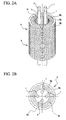
- FIG. 1A and FIG. 2A are perspective views each schematically illustrating a method of annealing a laminated core according to a first embodiment.
- FIG 1B and FIG. 2B are plan views each schematically illustrating a method of annealing a laminated core according to the first embodiment.
- the method of annealing a laminated core according to the first embodiment is capable of annealing a laminated core 9 having a conventional general configuration.
- the configuration of the laminated core 9 will be briefly described below.
- the laminated core 9 is formed by laminating electromagnetic steel sheets 90 that have been punched into a predetermined shape, and has a hollow cylindrical shape as a whole.
- the laminated core 9 has an inner peripheral surface 9a having teeth 91 formed thereon.
- the teeth 91 are each configured so as to protrude toward the center in the radial direction, and are arranged in the circumferential direction so as to be spaced away from each other at a predetermined distance.
- the method of annealing a laminated core according to the first embodiment employs one or more first heater(s) 1 that radiates infrared light for heating the laminated core 9.
- the first heater(s) 1 is disposed so as to extend parallel to the direction of the central axis of the laminated core 9. More specifically, the first heater(s) 1 includes, for example, a bar-like halogen heater (also referred to as a halogen lamp heater) that radiates a near infrared light (infrared light with the wavelength bandwidth ranging from 0.78 ⁇ m to 2.0 ⁇ m) or infrared light with the wavelength bandwidth of near infrared.
- a bar-like halogen heater also referred to as a halogen lamp heater
- the halogen heater has, for example, a configuration in which a tungsten filament is provided within a cylindrical quartz glass tube, and inert gas and halogen material are enclosed therein. Further, the tungsten filament radiates the infrared light upon application of electric power.
- halogen heaters may be applied to the first heater 1 in the first embodiment. Thus, a detailed description thereof will be omitted.
- the one or more first heater(s) 1 is inserted into the inner space of the laminated core 9, and is provided so as to be able to radiate infrared light directly onto the surface of the teeth 91.
- the first heater 1 that can radiate the infrared light toward all circumferential directions is provided at the center of inner space of the laminated core 9.
- the first heaters 1 are provided at positions brought close to the teeth 91 formed on the inner peripheral surface 9a of the laminated core 9 (in other words, at positions shifted from the center of the inner space of the laminated core 9 toward the outward in the radial direction).
- the axis of the one or more bar-like first heater(s) 1 prefferably be located parallel to the central axis direction of the laminated core 9 so as to be able to uniformly heat the entire length of the teeth 91 in the central axis direction.
- the first heater(s) 1 can directly radiate the infrared light that has uniform intensity onto the entire length of the teeth 91 in the central axis direction.
- the distances between the first heater(s) 1 and the inner peripheral surface 9a of the laminated core 9 or the surface of each of the teeth 91 are uniformly set.
- a plurality of the first heaters 1 are arranged in the circumferential direction at equal intervals.
- the laminated core 9 is heated using the first heater(s) 1 until the laminated core 9 reaches a target temperature. Since the first heater(s) 1 is disposed in the inner space of the laminated core 9, the laminated core 9 is heated from the inner space (in other words, the inner peripheral surface 9a having the teeth 91 formed thereon).
- the target temperature is preferably set to 700°C or higher. Further, the target temperature may be set to 750°C, which is equal to the heating temperature in the conventional method of annealing a laminated core.
- the laminated core 9 After the laminated core 9 is heated to the target temperature, heating by the first heater(s) 1 is stopped. Then, the laminated core 9 is gradually cooled.
- the conditions of the gradual cooling may be the same as those of the conventional method of annealing a laminated core. For example, conventional general furnace cooling or air cooling may be used. Thus, explanation thereof will be omitted.
- the laminated core 9 it is preferable to heat and cool the laminated core 9 in a non-oxidizing environment to prevent oxidization of the electromagnetic steel sheets 90 forming the laminated core 9.
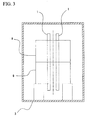
- a non-oxidizing environment it may be possible to employ a configuration in which a chamber 3 as illustrated in FIG 3 is filled with a non-oxidizing gas, and the laminated core 9 is heated and cooled within the chamber 3.
- the configuration of the chamber 3 is not specifically limited, and various types of conventionally known chambers may be used. This means that it is only necessary to use a configuration that can maintain the inside of the chamber to be the non-oxidizing environment.
- the laminated core 9 is heated using the first heater(s) 1, and hence, it may be possible that the chamber 3 does not have any heater.
- the laminated core 9 is heated from the inner space with the infrared light radiated from the first heater(s) 1. Since the one or more first heater(s) 1 is disposed in the inner spaced of the cylindrical laminated core 9, the infrared light can be uniformly radiated throughout the entire surface of the teeth 91 formed on the inner peripheral surface 9a of the laminated core 9. Further, compared to the method of annealing a laminated core employing the conventional heating furnace, with the first embodiment according to the present invention, it is possible to bring the heat source (infrared light source) close to the surfaces of the teeth 91, so that the laminated core 9 can be uniformly heated in a short period of time.
- the heat source infrared light source
- the first embodiment it is possible to start the gradual cooling immediately after the laminated core 9 reaches the target temperature, without the need to keep heating for the purpose of making temperatures uniform. Thus, it is possible to omit the "time required for making temperatures uniform," and reduce the heating time.
- each of the electromagnetic steel sheets 90 subjected to the punching process has the outer peripheral surface 9b having a substantially simple circular shape, whereas the inner peripheral surface 9a has teeth 91 formed thereon and hence, has an uneven surface.
- the inner peripheral surface 9a of the laminated core 9 has an elongated cut end, and has increased strain.
- the first heater 1 is disposed in the inner space of the laminated core 9.
- the laminated core 9 is heated from the inner space thereof by the infrared light that is radiated directly onto the surface of each of the teeth 91 formed on the inner peripheral surface 9a of the laminated core 9.
- the inner peripheral surface 9a reaches the target temperature earlier than the outer peripheral surface 9b, and hence, it is possible to subject the inner peripheral surface 9a to the target temperature longer than the outer peripheral surface 9b. This makes it possible to enhance the effect of annealing on the inner peripheral surface 9a, and reduce iron loss.
- the laminated cores 9 are disposed so as to be layered (or arranged) in the central axis direction, and one or more first heater(s) 1 is disposed so as to collectively penetrate the inner space of the layered laminated cores 9.
- first heater(s) 1 is disposed so as to collectively penetrate the inner space of the layered laminated cores 9.
- FIG. 1A, FIG. 1B , FIG 2A, and FIG. 2B each illustrate a configuration in which two laminated cores 9 are layered.
- the number of laminated cores 9 layered is not limited.
- FIG 1A, FIG. 1B , FIG 2A, and FIG 2B each illustrate a configuration in which the first heater(s) 1 is formed in a straight manner.
- the shape of the first heater 1 is not limited.
- the first heater 1 may have a U-shape.
- FIG. 2A and FIG 2B each illustrate a configuration in which four first heaters 1 are used.
- the number of the first heaters 1 is not limited.
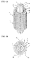
- FIG 4A is a perspective view schematically illustrating a method of annealing a laminated core according to the second embodiment.
- FIG. 4B is a plan view schematically illustrating a method of annealing a laminated core according to the second embodiment.
- the first heaters 1 are inserted in the inner space of the laminated core 9, and are disposed so as to be brought close to the teeth 91. Further, a first separator 2a is provided between the first heaters 1.
- the first separator 2a has a function of blocking the infrared light coming from the adjacent first heaters 1 in a manner such that the first heaters 1 do not directly radiate the infrared light onto each other. Further, the first separator 2a also has a function of reflecting the infrared light radiated from each of the first heaters 1 toward the surface of the teeth 91.
- the first separator 2a is made out of a material that blocks and reflects the infrared light.
- the first separator 2a is made out of white ceramic or aluminum.
- the first separator 2a has a portion that intervenes between the first heaters 1.
- the first separator 2a has sheet-like portions protruding radially outward, and each of these sheet-like portions intervenes between the first heaters 1.
- the first separator 2a has a configuration in which recessed portions extending along the central axis direction of the laminated core 9 are formed on the perimeter of the first separator 2a. In the recessed portions, the first heaters 1 are placed.
- first separator 2a are disposed between the adjacent first heaters 1. It is only necessary that the first separator 2a has a portion that intervenes between the first heaters 1 and has a configuration that can prevent the first heaters 1 from directly radiating the infrared light onto each other.
- the second embodiment it is possible to obtain a similar operation and effect to the first embodiment. Further, according to the second embodiment, with the first separator 2a, it is possible to prevent the first heaters 1 from directly radiating the infrared light onto each other. Thus, it is possible to prevent the first heaters 1 from directly heating each other, thereby protecting the first heaters 1.
- the first separator 2a reflects the infrared light radiated from the first heaters 1 toward the teeth 91.
- FIG 5A is a perspective view schematically illustrating a method of annealing a laminated core according to the third embodiment.
- FIG 5B is a plan view schematically illustrating a method of annealing a laminated core according to the third embodiment.
- the first heaters 1 are inserted in the inner space of the laminated core 9, and are disposed between the teeth 91 formed on the inner peripheral surface 9a of the laminated core 9. Further, the laminated core 9 is heated from the inner space by the first heaters 1 disposed between the teeth 91.
- the third embodiment it is possible to bring the first heaters 1 close to the surface of the teeth 91 formed on the inner peripheral surface 9a of the laminated core 9.
- the first heaters 1 are disposed radially inward of the teeth 91 (in other words, located closer to the center of the laminated core 9)
- This makes it possible to further improve the thermal efficiency, whereby it is possible to further reduce the heating time.
- the teeth 91 formed on the inner peripheral surface 9a of the laminated core 9 it is possible to prevent the first heaters 1 from radiating the infrared light directly onto each other.
- the teeth 91 formed on the inner peripheral surface 9a of the laminated core 9 function as the first separator 2a in the second embodiment.
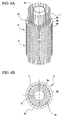
- FIG 6A is a perspective view schematically illustrating a method of annealing a laminated core according to the third embodiment.
- FIG 6B is a plan view schematically illustrating a method of annealing a laminated core according to the third embodiment.
- the first heaters 1 are inserted in the inner space of the laminated core 9, and are disposed between the adjacent teeth 91 formed on the inner peripheral surface 9a of the laminated core 9.
- a second separator 2b is disposed closer to the center in the radial direction than each of the teeth 91 (in other words, in the inner space) in a manner such that the second separator 2b extends along the central axis direction of the laminated core 9.
- the second separator 2b has a function of reflecting, toward the radially outward direction, the infrared light radiated from each of the first heaters 1 toward the center in the radial direction. It may be possible to employ, for example, a configuration in which the second separator 2b has a cylindrical or column-like shape that can be inserted in the inner space of the laminated core 9.
- the second separator 2b is formed by a material that blocks and reflects the infrared light.
- the second separator 2b is made out of white ceramic or aluminum.
- the fourth embodiment it is possible to obtain a similar operation and effect to the third embodiment. Further, in the fourth embodiment, the infrared light radiated from each of the first heaters 1 toward the center in the radial direction is reflected by the second separator 2b toward the radially outward direction (in other words, toward the inner peripheral surface 9a of the teeth 91). This makes it possible to further improve the thermal efficiency, whereby it is possible to further reduce the heating time.
- FIG 7A is a perspective view schematically illustrating a method of annealing a laminated core according to a fifth embodiment.
- FIG. 7B is a plan view schematically illustrating a method of annealing a laminated core according to the fifth embodiment.
- the first heaters 1 are inserted in the inner space of the laminated core 9, and second heaters 11 extending along the central axis direction of the laminated core 9 are disposed at the outer peripheral side of the laminated core 9, thereby applying heat.
- FIG 7A and FIG 7B each illustrate a configuration in which the first embodiment is applied for the first heaters 1 inserted in the inner space of the laminated core 9.
- the fifth embodiment it is possible to obtain a similar operation and effect to each of the embodiments described above. Further, according to the fifth embodiment, heat is applied to the laminated core 9 from the outer peripheral side. Thus, it is possible to increase the amount of heat per unit of time applied to the laminated core 9. Further, with the configuration in which the laminated core 9 is also heated from the outer peripheral side, the heat applied from the inner side surface 9a can be prevented from moving to the outer peripheral surface 9b and radiating from the outer peripheral surface 9b toward the outside. Thus, it is possible to further reduce the time required for heating the laminated core 9.
- the present inventor annealed the laminated core 9 through a method of heating the laminated core 9 using the first heater 1, and then cooling the laminated core 9. Then, temperatures of the laminated core 9 were measured during heating, and the effect of reducing the iron loss resulting from annealing was measured.
- FIG. 8 is a perspective view schematically illustrating a configuration of the laminated core 9 used in the examples, and positions of points where temperatures were measured.
- the laminated core 9 has a cylindrical configuration as a whole.
- the teeth 91 protruding radially toward the center are formed.
- the laminated core 9 has an outside diameter (maximum) Do of approximately 180 mm, an inside diameter (minimum) D 1 of approximately 115 mm, and a length L in the central axis direction of approximately 55 mm.
- the number of measurement points for temperatures is eight, and the measurement points are denoted as A to H.
- the measurement points A and E are located at each end of the teeth 91 in the central axis direction of the inner peripheral surface 9a.
- the measurement points B and F are located at the center of the teeth 91 in the central axis direction of the inner peripheral surface 9a.
- the measurement points C and G are each located at the edge of the outer peripheral surface in the central axis direction.
- the measurement points D and H are located at the center of the outer peripheral surface in the central axis direction. Note that the measurement points A, B, C, and D are located at the same positions in terms of the circumferential direction. Similarly, the measurement points E, F, G, and H are located at the same positions in terms of the circumferential direction. Further, the measurement points A, B, C, and D are located so as to be positionally shifted from the measurement points E, F, G, and H by 90° in the circumferential direction.
- each of the teeth 91 of the laminated core 9 is set to 25 mm.
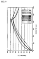
- FIG. 9 is a graph showing changes in temperatures at each of the measurement points.
- FIG. 10 is a table showing the maximum temperatures at each of the measurement points. As shown in FIG. 9 and FIG. 10 , with the heating for 870 seconds, all the measurement points reached the target temperature of 700°C or higher. As a result, compared to the case where annealing is not applied, the laminated core 9 having annealing applied thereto exhibited approximately a 15% reduction in iron loss.
- the effect of reducing the iron loss resulting from annealing can be obtained by heating for 870 seconds. It is confirmed that, according to the examples of the present invention, it is possible to significantly reduce the heating time, while several hours of heating are required with the conventional method of annealing a laminated core employing the heating furnace. Further, it is confirmed that, according to the examples of the present invention, the effect of reducing the iron loss resulting from annealing can be obtained even if heating is not maintained after the laminated core 9 reaches the target temperature to make temperatures uniform. As described above, it is confirmed that, according to the examples of the present invention, it is possible to improve the productivity of the laminated core 9 by reducing the heating time.
- the numbers of the first heaters 1 and the second heaters 11 used for heating the laminated core 9 are not limited.
- the numbers of the first heaters 1 and the second heaters 11 are appropriately set depending on the size or shape of the laminated core 9 to be heated.
- the configurations of the first heater 1 and the second heater 11 are not limited to the straightly shaped configuration.
- the first heater 1 and the second heater 11 may be configured to have a U-shaped configuration.
- the configuration in which two laminated cores 9 are layered in the central axis direction and heated simultaneously is illustrated.
- the number of laminated cores 9 heated simultaneously is not limited. It may be possible to employ a configuration in which a single laminated core 9 is heated, or a configuration in which three or more laminated cores 9 are layered, and are heated simultaneously.
- the laminated core 9 formed by laminating electromagnetic steel sheets is used as the metal member.
- the metal member is not limited to the laminated core, and it is only necessary for the metal member to have a hollow cylindrical shape.
- the present invention is applicable to annealing applied for removing strain in the laminated core formed by laminating electromagnetic steel sheets. Further, the present invention is applicable not only to annealing applied to the laminated core formed by laminating the electromagnetic steel sheets but also to annealing applied to various kinds of laminated cores.
Landscapes
- Engineering & Computer Science (AREA)
- Chemical & Material Sciences (AREA)
- Mechanical Engineering (AREA)
- Materials Engineering (AREA)
- Organic Chemistry (AREA)
- Metallurgy (AREA)
- Physics & Mathematics (AREA)
- Thermal Sciences (AREA)
- Crystallography & Structural Chemistry (AREA)
- General Engineering & Computer Science (AREA)
- Power Engineering (AREA)
- Manufacturing & Machinery (AREA)
- Manufacturing Cores, Coils, And Magnets (AREA)
- Manufacture Of Motors, Generators (AREA)
- Heat Treatment Of Articles (AREA)
- Resistance Heating (AREA)
Abstract
Description
- The present invention relates to a method of annealing a metal member having a hollow cylindrical shape. More specifically, the present invention relates to a method of annealing a metal member favorable for annealing a laminated core formed by laminating, for example, electromagnetic steel sheets, and the annealing method is directed to removing strain to reduce iron losses. The present application claims priority based on Japanese Patent Application No.
2412-013403 - General laminated cores for use in electric motors are formed by punching an electromagnetic steel sheet into a predetermined shape, laminating the punched sheets, and joining the sheets, for example, through welding or caulking. However, during the punching, strain may occur in the electromagnetic steel sheet. Once the strain occurs in the electromagnetic steel sheet, the iron loss increases and energy efficiency of the electric motor deteriorates. Thus, for example, as described in
Patent Documents 1 to 3, annealing may be performed to remove the strain after the punched electromagnetic steel sheets are laminated and joined. -
- Patent Document 1: Japanese Unexamined Patent Application, First Publication No.
S54-1803 - Patent Document 2: Japanese Unexamined Patent Application, First Publication No.
H11-332183 - Patent Document 3: Japanese Unexamined Patent Application, First Publication No.
S59-123719 - The method of annealing a laminated core formed by the electromagnetic steel sheet includes, for example, heating to 750°C or higher using a heating furnace, keeping heating for approximately two hours so as to uniformly heat, and thereafter gradually cooling. As described above, to anneal the laminated core, it is necessary to heat the laminated core for a long period of time. This leads to a problem of poor productivity of annealing of the laminated core. In this regard, there is a demand to reduce the time required for heating to improve the productivity. In connection with the reduction in the time required for heating, for example,
Patent Document 3 discloses a configuration of induction heating applied to a laminated core. However,Patent Document 3 does not disclose any specific heating method. Further, as for the method of heating in a short period of time, there is a method of applying electric power to the laminated core to heat with Joule heating. However, with the method of heating through electric power, it is difficult to uniformly bring the electrodes into contact with the laminated core if the size of the laminated core is large. Thus, it is difficult to uniformly heat the laminated core in a short period of time. - The present invention has been made in view of the problems described above, and an object of the present invention is to reduce a time required for heating in annealing a metal member having a hollow cylindrical shape such as a laminated core formed by laminating electromagnetic steel sheets, thereby improving productivity.
- The following is a summary of the present invention.
- (1) An aspect of the present invention provides a method of annealing a metal member, including: disposing a first heater in an inner space of a hollow cylindrical metal member having an inner peripheral surface provided with multiple teeth protruding toward a center direction, the first heater radiating infrared light and being disposed so as to extend parallel to a direction of a central axis of the metal member; heating the metal member from the inner space by the first heater; and gradually cooling the metal member after heating.
- (2) In the method of annealing a metal member according to (1) above, first heaters may be arranged in a circumferential direction at an equal interval.
- (3) In the method of annealing a metal member according to (2) above, a first separator that blocks between the first heaters may be disposed so as to extend along the central axis of the metal member.
- (4) In the method of annealing a metal member according to (3) above, the first separator may be made of at least one of white ceramic and aluminum.
- (5) In the method of annealing a metal member according to (2) above, each of the first heaters may be disposed between the teeth.
- (6) In the method of annealing a metal member according to (5) above, a second separator that extends along the direction of the central axis of the metal member may be disposed in the inner space of the metal member.
- (7) In the method of annealing a metal member according to (6) above, the second separator may be made of at least one of white ceramic and aluminum.
- (8) In the method of annealing a metal member according to any one of (1) to (7) above, metal members may be layered in the direction of the central axis, the first heater may be inserted in the inner space of the metal members, and the metal members may be heated at the same time.
- (9) In the method of annealing a metal member according to (8) above, the first heater may be a halogen heater.
- (10) In the method of annealing a metal member according to (1) to (9) above, a second heater may be further disposed on a side of an outer periphery of the metal member so as to extend parallel to the direction of the central axis of the metal member, and the metal member may be heated by the second heater from the side of the outer periphery.
- (11) In the method of annealing a metal member according to (10) above, the second heater may be a heater that radiates infrared light.
- (12) In the method of annealing a metal member according to (11) above, the second heater may be a halogen heater.
- (13) In the method of annealing a metal member according to any one of (1) to (12) above, the metal member may be a laminated core formed by laminating electromagnetic steel sheets.
- According to the present invention, it is possible to heat the metal member from the inner space by infrared light radiated from a first heater disposed so as to extend parallel to the central axis direction of the metal member. Further, it is possible to bring the first heater close to the teeth at equal distances throughout the entire length of the central axis direction of each of the teeth formed on the inner peripheral surface of the metal member. This makes it possible to reduce the time required for heating, compared to the configuration of heating the metal member by a heating furnace. Thus, it is possible to improve productivity concerning annealing the metal member. Further, the teeth formed on the inner peripheral surface of the metal member can be heated, which makes it possible to maintain and enhance the effect of removing the strain occurring in the teeth, and further reducing the iron loss. As described above, according to the present invention, it is possible to improve the productivity by reducing the heating time, and at the same time, to prevent deterioration in the effect of reducing iron loss during annealing.
-
-
FIG. 1A is a perspective view schematically illustrating a method of annealing a laminated core according to a first embodiment of the present invention. -
FIG. 1B is a plan view schematically illustrating a method of annealing a laminated core according to the first embodiment of the present invention. -
FIG 2A is a perspective view schematically illustrating a method of annealing a laminated core according to the first embodiment of the present invention. -
FIG. 2B is a plan view schematically illustrating a method of annealing a laminated core according to the first embodiment of the present invention. -
FIG. 3 is a sectional view schematically illustrating a method of annealing a laminated core according to the first embodiment of the present invention. -
FIG. 4A is a perspective view schematically illustrating a method of annealing a laminated core according to a second embodiment of the present invention. -
FIG 4B is a plan view schematically illustrating a method of annealing a laminated core according to the second embodiment of the present invention. -
FIG. 5A is a perspective view schematically illustrating a method of annealing a laminated core according to a third embodiment of the present invention. -
FIG. 5B is a plan view schematically illustrating a method of annealing a laminated core according to the third embodiment of the present invention. -
FIG. 6A is a perspective view schematically illustrating a method of annealing a laminated core according to a fourth embodiment of the present invention. -
FIG. 6B is a plan view schematically illustrating a method of annealing a laminated core according to the fourth embodiment of the present invention. -
FIG. 7A is a perspective view schematically illustrating a method of annealing a laminated core according to a fifth embodiment of the present invention. -
FIG. 7B is a plan view schematically illustrating a method of annealing a laminated core according to the fifth embodiment of the present invention. -
FIG. 8 is a perspective view schematically illustrating a structure of a laminated core used in Examples of the present invention, and temperature measurement points. -
FIG 9 is a graph showing changes with time in temperatures of a laminated core in Examples of the present invention. -
FIG. 10 is a table showing the maximum temperatures at measurement points of the laminated core in Examples of the present invention. - Hereinbelow, embodiments and examples of the present invention will be described in detail with reference to the drawings. In this specification, a laminated core is described as an example of the metal member. However, the metal member according to the present invention is not limited to the laminated core.
-
FIG. 1A andFIG. 2A are perspective views each schematically illustrating a method of annealing a laminated core according to a first embodiment.FIG 1B andFIG. 2B are plan views each schematically illustrating a method of annealing a laminated core according to the first embodiment. - The method of annealing a laminated core according to the first embodiment is capable of annealing a
laminated core 9 having a conventional general configuration. The configuration of thelaminated core 9 will be briefly described below. Thelaminated core 9 is formed by laminatingelectromagnetic steel sheets 90 that have been punched into a predetermined shape, and has a hollow cylindrical shape as a whole. Thelaminated core 9 has an innerperipheral surface 9a having teeth 91 formed thereon. Theteeth 91 are each configured so as to protrude toward the center in the radial direction, and are arranged in the circumferential direction so as to be spaced away from each other at a predetermined distance. - As illustrated in
FIG. 1A, FIG. 1B ,FIG. 2A, and FIG. 2B , the method of annealing a laminated core according to the first embodiment employs one or more first heater(s) 1 that radiates infrared light for heating thelaminated core 9. The first heater(s) 1 is disposed so as to extend parallel to the direction of the central axis of thelaminated core 9. More specifically, the first heater(s) 1 includes, for example, a bar-like halogen heater (also referred to as a halogen lamp heater) that radiates a near infrared light (infrared light with the wavelength bandwidth ranging from 0.78 µm to 2.0 µm) or infrared light with the wavelength bandwidth of near infrared. The halogen heater has, for example, a configuration in which a tungsten filament is provided within a cylindrical quartz glass tube, and inert gas and halogen material are enclosed therein. Further, the tungsten filament radiates the infrared light upon application of electric power. - It should be noted that various types of known halogen heaters may be applied to the
first heater 1 in the first embodiment. Thus, a detailed description thereof will be omitted. - The one or more first heater(s) 1 is inserted into the inner space of the
laminated core 9, and is provided so as to be able to radiate infrared light directly onto the surface of theteeth 91. For example, in the case of the configuration in which a singlefirst heater 1 is used as illustrated inFIG. 1A and FIG. 1B , thefirst heater 1 that can radiate the infrared light toward all circumferential directions is provided at the center of inner space of thelaminated core 9. Further, in the case of the configuration in which a plurality offirst heaters 1 are used as illustrated inFIG 2A and FIG 2B , thefirst heaters 1 are provided at positions brought close to theteeth 91 formed on the innerperipheral surface 9a of the laminated core 9 (in other words, at positions shifted from the center of the inner space of thelaminated core 9 toward the outward in the radial direction). - Further, it is preferable for the axis of the one or more bar-like first heater(s) 1 to be located parallel to the central axis direction of the
laminated core 9 so as to be able to uniformly heat the entire length of theteeth 91 in the central axis direction. With these configurations, it is possible to dispose the first heater(s) 1 so as to be brought close to theteeth 91 with equal distances maintained throughout the entire length of theteeth 91. Thus, the first heater(s) 1 can directly radiate the infrared light that has uniform intensity onto the entire length of theteeth 91 in the central axis direction. Further, the distances between the first heater(s) 1 and the innerperipheral surface 9a of thelaminated core 9 or the surface of each of theteeth 91 are uniformly set. Furthermore, a plurality of thefirst heaters 1 are arranged in the circumferential direction at equal intervals. - Then, the
laminated core 9 is heated using the first heater(s) 1 until thelaminated core 9 reaches a target temperature. Since the first heater(s) 1 is disposed in the inner space of thelaminated core 9, thelaminated core 9 is heated from the inner space (in other words, the innerperipheral surface 9a having theteeth 91 formed thereon). Note that the target temperature is preferably set to 700°C or higher. Further, the target temperature may be set to 750°C, which is equal to the heating temperature in the conventional method of annealing a laminated core. - After the
laminated core 9 is heated to the target temperature, heating by the first heater(s) 1 is stopped. Then, thelaminated core 9 is gradually cooled. The conditions of the gradual cooling (such as cooling method and temperature history) may be the same as those of the conventional method of annealing a laminated core. For example, conventional general furnace cooling or air cooling may be used. Thus, explanation thereof will be omitted. - In the first embodiment, gradual cooling starts immediately after the
laminated core 9 reaches the target temperature. In other words, in the conventional method of annealing a laminated core that heats using a heating furnace, even after thelaminated core 9 reaches the target temperature, heating continues for a predetermined period of time (for example, for approximately 2 hours) to make temperatures uniform. Thus, in the conventional method of annealing a laminated core, the "time required for thelaminated core 9 to reach the target temperature" and the "time required for making temperatures uniform" are necessary as the heating time. On the other hand, in the method of annealing a laminated core according to the first embodiment, only the "time required for thelaminated core 9 to reach the target temperature" is necessary as the heating time, and the "time required for making temperatures uniform" is not necessary. - It is preferable to heat and cool the
laminated core 9 in a non-oxidizing environment to prevent oxidization of theelectromagnetic steel sheets 90 forming thelaminated core 9. For example, it may be possible to employ a configuration in which achamber 3 as illustrated inFIG 3 is filled with a non-oxidizing gas, and thelaminated core 9 is heated and cooled within thechamber 3. Note that the configuration of thechamber 3 is not specifically limited, and various types of conventionally known chambers may be used. This means that it is only necessary to use a configuration that can maintain the inside of the chamber to be the non-oxidizing environment. Further, in the first embodiment, thelaminated core 9 is heated using the first heater(s) 1, and hence, it may be possible that thechamber 3 does not have any heater. - According to the first embodiment, the
laminated core 9 is heated from the inner space with the infrared light radiated from the first heater(s) 1. Since the one or more first heater(s) 1 is disposed in the inner spaced of the cylindricallaminated core 9, the infrared light can be uniformly radiated throughout the entire surface of theteeth 91 formed on the innerperipheral surface 9a of thelaminated core 9. Further, compared to the method of annealing a laminated core employing the conventional heating furnace, with the first embodiment according to the present invention, it is possible to bring the heat source (infrared light source) close to the surfaces of theteeth 91, so that thelaminated core 9 can be uniformly heated in a short period of time. This makes it possible to reduce the "time required for thelaminated core 9 to reach the target temperature." In particular, with the configuration employing the first heater(s) 1 radiating the near infrared light, it is possible to improve responsiveness concerning raising temperatures. Thus, it is possible to raise temperatures of thelaminated core 9 in a short period of time. - Further, according to the first embodiment, it is possible to start the gradual cooling immediately after the
laminated core 9 reaches the target temperature, without the need to keep heating for the purpose of making temperatures uniform. Thus, it is possible to omit the "time required for making temperatures uniform," and reduce the heating time. - As described above, according to the first embodiment, it is possible to reduce the heating time in annealing, whereby it is possible to improve the productivity concerning the
laminated core 9. - Further, according to the first embodiment, it is possible to reduce iron loss while reducing the time required for heating the
laminated core 9. In other words, each of theelectromagnetic steel sheets 90 subjected to the punching process has the outerperipheral surface 9b having a substantially simple circular shape, whereas the innerperipheral surface 9a hasteeth 91 formed thereon and hence, has an uneven surface. Thus, compared to the outerperipheral surface 9b, the innerperipheral surface 9a of thelaminated core 9 has an elongated cut end, and has increased strain. Thus, to reduce the iron loss, it is necessary to enhance the effect of annealing especially on the innerperipheral surface 9a to remove the strain. In the first embodiment, thefirst heater 1 is disposed in the inner space of thelaminated core 9. Thelaminated core 9 is heated from the inner space thereof by the infrared light that is radiated directly onto the surface of each of theteeth 91 formed on the innerperipheral surface 9a of thelaminated core 9. Thus, it is possible to reliably raise temperatures of the innerperipheral surface 9a of thelaminated core 9 to the target temperature. Further, the innerperipheral surface 9a reaches the target temperature earlier than the outerperipheral surface 9b, and hence, it is possible to subject the innerperipheral surface 9a to the target temperature longer than the outerperipheral surface 9b. This makes it possible to enhance the effect of annealing on the innerperipheral surface 9a, and reduce iron loss. As described above, according to the first embodiment, it is possible to reduce iron loss while reducing the heating time. - In the case where a plurality of
laminated cores 9 are annealed, thelaminated cores 9 are disposed so as to be layered (or arranged) in the central axis direction, and one or more first heater(s) 1 is disposed so as to collectively penetrate the inner space of the layeredlaminated cores 9. With the configuration as described above, it is possible to heat thelaminated cores 9 at the same time, and hence, it is possible to improve the productivity of thelaminated cores 9. Note thatFIG. 1A, FIG. 1B ,FIG 2A, and FIG. 2B each illustrate a configuration in which twolaminated cores 9 are layered. However, the number oflaminated cores 9 layered is not limited. - Further,
FIG 1A, FIG. 1B ,FIG 2A, and FIG 2B each illustrate a configuration in which the first heater(s) 1 is formed in a straight manner. However, the shape of thefirst heater 1 is not limited. For example, thefirst heater 1 may have a U-shape. Yet further,FIG. 2A and FIG 2B each illustrate a configuration in which fourfirst heaters 1 are used. However, the number of thefirst heaters 1 is not limited. - Next, a second embodiment according to the present invention will be described. Note that the configuration common to that of the first embodiment will not be described.
FIG 4A is a perspective view schematically illustrating a method of annealing a laminated core according to the second embodiment.FIG. 4B is a plan view schematically illustrating a method of annealing a laminated core according to the second embodiment. - As illustrated in
FIG. 4A and FIG 4B , thefirst heaters 1 are inserted in the inner space of thelaminated core 9, and are disposed so as to be brought close to theteeth 91. Further, afirst separator 2a is provided between thefirst heaters 1. Thefirst separator 2a has a function of blocking the infrared light coming from the adjacentfirst heaters 1 in a manner such that thefirst heaters 1 do not directly radiate the infrared light onto each other. Further, thefirst separator 2a also has a function of reflecting the infrared light radiated from each of thefirst heaters 1 toward the surface of theteeth 91. To this end, thefirst separator 2a is made out of a material that blocks and reflects the infrared light. For example, thefirst separator 2a is made out of white ceramic or aluminum. - The
first separator 2a has a portion that intervenes between thefirst heaters 1. For example, as illustrated inFIG 4A and FIG. 4B , thefirst separator 2a has sheet-like portions protruding radially outward, and each of these sheet-like portions intervenes between thefirst heaters 1. In other words, thefirst separator 2a has a configuration in which recessed portions extending along the central axis direction of thelaminated core 9 are formed on the perimeter of thefirst separator 2a. In the recessed portions, thefirst heaters 1 are placed. - Moreover, it may be possible to employ a configuration in which independent
first separators 2a are disposed between the adjacentfirst heaters 1. It is only necessary that thefirst separator 2a has a portion that intervenes between thefirst heaters 1 and has a configuration that can prevent thefirst heaters 1 from directly radiating the infrared light onto each other. - According to the second embodiment, it is possible to obtain a similar operation and effect to the first embodiment. Further, according to the second embodiment, with the
first separator 2a, it is possible to prevent thefirst heaters 1 from directly radiating the infrared light onto each other. Thus, it is possible to prevent thefirst heaters 1 from directly heating each other, thereby protecting thefirst heaters 1. - Further, the
first separator 2a reflects the infrared light radiated from thefirst heaters 1 toward theteeth 91. Thus, according to the second embodiment, it is possible to improve the thermal efficiency, whereby it is possible to further reduce the time required for heating thelaminated core 9. - Next, a third embodiment according to the present invention will be described. Note that the configuration common to that of the first embodiment will not be described.
FIG 5A is a perspective view schematically illustrating a method of annealing a laminated core according to the third embodiment.FIG 5B is a plan view schematically illustrating a method of annealing a laminated core according to the third embodiment. - As illustrated in
FIG. 5A and FIG. 5B , in the third embodiment, thefirst heaters 1 are inserted in the inner space of thelaminated core 9, and are disposed between theteeth 91 formed on the innerperipheral surface 9a of thelaminated core 9. Further, thelaminated core 9 is heated from the inner space by thefirst heaters 1 disposed between theteeth 91. - According to the third embodiment, it is possible to bring the
first heaters 1 close to the surface of theteeth 91 formed on the innerperipheral surface 9a of thelaminated core 9. In particular, compared to the configuration in which thefirst heaters 1 are disposed radially inward of the teeth 91 (in other words, located closer to the center of the laminated core 9), it is possible to more strongly radiate the infrared light to the end surface of theteeth 91 in the circumferential direction (in other words, the surface facing the adjacent tooth 91). This makes it possible to further improve the thermal efficiency, whereby it is possible to further reduce the heating time. - Further, according to the third embodiment, with the
teeth 91 formed on the innerperipheral surface 9a of thelaminated core 9, it is possible to prevent thefirst heaters 1 from radiating the infrared light directly onto each other. In other words, it is possible to make theteeth 91 formed on the innerperipheral surface 9a of thelaminated core 9 function as thefirst separator 2a in the second embodiment. Thus, it is possible to protect thefirst heaters 1. - Next, a fourth embodiment according to the present invention will be made. The fourth embodiment has a configuration in which the separator is applied to the third embodiment. Thus, the configuration common to that of the third embodiment will not be described.
FIG 6A is a perspective view schematically illustrating a method of annealing a laminated core according to the third embodiment.FIG 6B is a plan view schematically illustrating a method of annealing a laminated core according to the third embodiment. - As illustrated in
FIG. 6A and FIG. 6B , in the fourth embodiment, thefirst heaters 1 are inserted in the inner space of thelaminated core 9, and are disposed between theadjacent teeth 91 formed on the innerperipheral surface 9a of thelaminated core 9. Further, asecond separator 2b is disposed closer to the center in the radial direction than each of the teeth 91 (in other words, in the inner space) in a manner such that thesecond separator 2b extends along the central axis direction of thelaminated core 9. Thesecond separator 2b has a function of reflecting, toward the radially outward direction, the infrared light radiated from each of thefirst heaters 1 toward the center in the radial direction. It may be possible to employ, for example, a configuration in which thesecond separator 2b has a cylindrical or column-like shape that can be inserted in the inner space of thelaminated core 9. - Further, the
second separator 2b is formed by a material that blocks and reflects the infrared light. For example, thesecond separator 2b is made out of white ceramic or aluminum. - According to the fourth embodiment, it is possible to obtain a similar operation and effect to the third embodiment. Further, in the fourth embodiment, the infrared light radiated from each of the
first heaters 1 toward the center in the radial direction is reflected by thesecond separator 2b toward the radially outward direction (in other words, toward the innerperipheral surface 9a of the teeth 91). This makes it possible to further improve the thermal efficiency, whereby it is possible to further reduce the heating time. - Next, a fifth embodiment will be described.
FIG 7A is a perspective view schematically illustrating a method of annealing a laminated core according to a fifth embodiment.FIG. 7B is a plan view schematically illustrating a method of annealing a laminated core according to the fifth embodiment. As illustrated inFIG. 7A andFIG 7B , in the fifth embodiment, thefirst heaters 1 are inserted in the inner space of thelaminated core 9, andsecond heaters 11 extending along the central axis direction of thelaminated core 9 are disposed at the outer peripheral side of thelaminated core 9, thereby applying heat. Note thatFIG 7A andFIG 7B each illustrate a configuration in which the first embodiment is applied for thefirst heaters 1 inserted in the inner space of thelaminated core 9. However, it may be possible to employ a configuration in which any of the second to the fourth embodiments is applied. - According to the fifth embodiment, it is possible to obtain a similar operation and effect to each of the embodiments described above. Further, according to the fifth embodiment, heat is applied to the
laminated core 9 from the outer peripheral side. Thus, it is possible to increase the amount of heat per unit of time applied to thelaminated core 9. Further, with the configuration in which thelaminated core 9 is also heated from the outer peripheral side, the heat applied from theinner side surface 9a can be prevented from moving to the outerperipheral surface 9b and radiating from the outerperipheral surface 9b toward the outside. Thus, it is possible to further reduce the time required for heating thelaminated core 9. - Next, examples of the present invention will be described. The present inventor annealed the
laminated core 9 through a method of heating thelaminated core 9 using thefirst heater 1, and then cooling thelaminated core 9. Then, temperatures of thelaminated core 9 were measured during heating, and the effect of reducing the iron loss resulting from annealing was measured. -
FIG. 8 is a perspective view schematically illustrating a configuration of thelaminated core 9 used in the examples, and positions of points where temperatures were measured. As illustrated inFIG. 8 , thelaminated core 9 has a cylindrical configuration as a whole. Then, on the innerperipheral surface 9a of thelaminated core 9, theteeth 91 protruding radially toward the center are formed. Thelaminated core 9 has an outside diameter (maximum) Do of approximately 180 mm, an inside diameter (minimum) D1 of approximately 115 mm, and a length L in the central axis direction of approximately 55 mm. The number of measurement points for temperatures is eight, and the measurement points are denoted as A to H. The measurement points A and E are located at each end of theteeth 91 in the central axis direction of the innerperipheral surface 9a. The measurement points B and F are located at the center of theteeth 91 in the central axis direction of the innerperipheral surface 9a. The measurement points C and G are each located at the edge of the outer peripheral surface in the central axis direction. The measurement points D and H are located at the center of the outer peripheral surface in the central axis direction. Note that the measurement points A, B, C, and D are located at the same positions in terms of the circumferential direction. Similarly, the measurement points E, F, G, and H are located at the same positions in terms of the circumferential direction. Further, the measurement points A, B, C, and D are located so as to be positionally shifted from the measurement points E, F, G, and H by 90° in the circumferential direction. - As illustrated in
FIG. 8 , four bar-like halogen heaters are inserted in the inner space of thelaminated core 9, and are arranged in the circumferential direction at equal intervals. The distance from the innerperipheral surface 9a of each of theteeth 91 of thelaminated core 9 to each of thefirst heaters 1 is set to 25 mm. - Under the conditions described above, the
laminated core 9 was heated for 870 seconds, and immediately after this, was gradually cooled (air cooled). In the heating, the electric power supplied to thefirst heaters 1 was set to approximately 2,550 W. Of the supplied electric power, approximately 86% of the power is converted into infrared light. Further, the light radiation length was set to 150 mm. Thus, the amount of heat radiated from thefirst heaters 1 was approximately 15 W/mm.FIG. 9 is a graph showing changes in temperatures at each of the measurement points.FIG. 10 is a table showing the maximum temperatures at each of the measurement points. As shown inFIG. 9 andFIG. 10 , with the heating for 870 seconds, all the measurement points reached the target temperature of 700°C or higher. As a result, compared to the case where annealing is not applied, thelaminated core 9 having annealing applied thereto exhibited approximately a 15% reduction in iron loss. - As described above, with these examples, it is confirmed that the effect of reducing the iron loss resulting from annealing can be obtained by heating for 870 seconds. It is confirmed that, according to the examples of the present invention, it is possible to significantly reduce the heating time, while several hours of heating are required with the conventional method of annealing a laminated core employing the heating furnace. Further, it is confirmed that, according to the examples of the present invention, the effect of reducing the iron loss resulting from annealing can be obtained even if heating is not maintained after the
laminated core 9 reaches the target temperature to make temperatures uniform. As described above, it is confirmed that, according to the examples of the present invention, it is possible to improve the productivity of thelaminated core 9 by reducing the heating time. - These are detailed descriptions of the embodiments according to the present invention with reference to the drawings. However, the embodiments and examples described above are merely specific examples of embodying the present invention. The technical scope of the present invention is not limited to the embodiments and examples described above. It may be possible to make various modifications to the present invention within the scope thereof, and these are also included in the technical scope of the present invention.
- For example, the numbers of the
first heaters 1 and thesecond heaters 11 used for heating thelaminated core 9 are not limited. The numbers of thefirst heaters 1 and thesecond heaters 11 are appropriately set depending on the size or shape of thelaminated core 9 to be heated. Further, the configurations of thefirst heater 1 and thesecond heater 11 are not limited to the straightly shaped configuration. For example, thefirst heater 1 and thesecond heater 11 may be configured to have a U-shaped configuration. Moreover, in the embodiments described above, the configuration in which twolaminated cores 9 are layered in the central axis direction and heated simultaneously is illustrated. However, the number oflaminated cores 9 heated simultaneously is not limited. It may be possible to employ a configuration in which a singlelaminated core 9 is heated, or a configuration in which three or morelaminated cores 9 are layered, and are heated simultaneously. - Further, in the descriptions above, the
laminated core 9 formed by laminating electromagnetic steel sheets is used as the metal member. However, in the present invention, the metal member is not limited to the laminated core, and it is only necessary for the metal member to have a hollow cylindrical shape. - The present invention is applicable to annealing applied for removing strain in the laminated core formed by laminating electromagnetic steel sheets. Further, the present invention is applicable not only to annealing applied to the laminated core formed by laminating the electromagnetic steel sheets but also to annealing applied to various kinds of laminated cores.
-
- 1:
- First heater
- 11:
- Second heater
- 2a:
- First separator
- 2b:
- Second separator
- 3:
- Chamber
- 9:
- Laminated core
- 9a:
- Inner peripheral surface of laminated core
- 9b:
- Outer peripheral surface of laminated core
- 90:
- Punched electromagnetic steel sheet
- 91:
- Tooth formed on inner peripheral surface of laminated core
Claims (13)
- A method of annealing a metal member, the method comprising:disposing a first heater in an inner space of a hollow cylindrical metal member having an inner peripheral surface provided with a plurality of teeth protruding toward a central direction, the first heater radiating infrared light and being disposed so as to extend parallel to a direction of a central axis of the metal member;heating the metal member from the inner space with the first heater; andgradually cooling the metal member after heating.
- The method of annealing a metal member, wherein
a plurality of the first heaters are arranged in a circumferential direction at equal intervals. - The method of annealing a metal member according to Claim 2, wherein
a first separator that acts as a block between the plurality of the first heaters is disposed so as to extend along the central axis of the metal member. - The method of annealing a metal member according to Claim 3, wherein
the first separator is made of at least one of white ceramic and aluminum. - The method of annealing a metal member according to Claim 2, wherein
each of the plurality of the first heaters is disposed between the plurality of teeth. - The method of annealing a metal member according to Claim 5, wherein
a second separator that extends along the direction of the central axis of the metal member is disposed in the inner space of the metal member. - The method of annealing a metal member according to Claim 6, wherein
the second separator is made of at least one of white ceramic and aluminum. - The method of annealing a metal member according to any one of Claim 1 to Claim 7, wherein
a plurality of the metal members are layered in the direction of the central axis,
the first heater is inserted in the inner space of the plurality of the metal members, and
the plurality of the metal members are heated simultaneously. - The method of annealing a metal member according to Claim 8, wherein
the first heater is a halogen heater. - The method of annealing a metal member according to any one of Claim 1 to Claim 7, wherein
a second heater is further disposed on a side of an outer periphery of the metal member so as to extend parallel to the direction of the central axis of the metal member, and
the metal member is heated by the second heater from the side of the outer periphery. - The method of annealing a metal member according to Claim 10, wherein
the second heater is a heater that radiates infrared light. - The method of annealing a metal member according to Claim 11, wherein
the second heater is a halogen heater. - The method of annealing a metal member according to any one of Claim I to Claim 7, wherein
the metal member is a laminated core formed by laminating a plurality of electromagnetic steel sheets.
Priority Applications (1)
| Application Number | Priority Date | Filing Date | Title |
|---|---|---|---|
| PL13741187T PL2713485T3 (en) | 2012-01-25 | 2013-01-22 | Metal member annealing method |
Applications Claiming Priority (2)
| Application Number | Priority Date | Filing Date | Title |
|---|---|---|---|
| JP2012013403 | 2012-01-25 | ||
| PCT/JP2013/051149 WO2013111726A1 (en) | 2012-01-25 | 2013-01-22 | Metal member annealing method |
Publications (3)
| Publication Number | Publication Date |
|---|---|
| EP2713485A1 true EP2713485A1 (en) | 2014-04-02 |
| EP2713485A4 EP2713485A4 (en) | 2015-08-19 |
| EP2713485B1 EP2713485B1 (en) | 2019-01-09 |
Family
ID=48873446
Family Applications (1)
| Application Number | Title | Priority Date | Filing Date |
|---|---|---|---|
| EP13741187.2A Active EP2713485B1 (en) | 2012-01-25 | 2013-01-22 | Metal member annealing method |
Country Status (6)
| Country | Link |
|---|---|
| US (1) | US10370733B2 (en) |
| EP (1) | EP2713485B1 (en) |
| JP (1) | JP6021270B2 (en) |
| CN (1) | CN103620926B (en) |
| PL (1) | PL2713485T3 (en) |
| WO (1) | WO2013111726A1 (en) |
Families Citing this family (11)
| Publication number | Priority date | Publication date | Assignee | Title |
|---|---|---|---|---|
| JP6102731B2 (en) * | 2013-12-26 | 2017-03-29 | 新日鐵住金株式会社 | Method for annealing laminated core |
| JP6201747B2 (en) * | 2013-12-26 | 2017-09-27 | 新日鐵住金株式会社 | Method for annealing laminated core |
| JP6102732B2 (en) * | 2013-12-26 | 2017-03-29 | 新日鐵住金株式会社 | Laminated core annealing equipment |
| JP6725209B2 (en) * | 2015-03-25 | 2020-07-15 | 日本製鉄株式会社 | High strength member for motor and method of manufacturing high strength member for motor |
| JP6658471B2 (en) * | 2016-11-25 | 2020-03-04 | トヨタ自動車株式会社 | Method for manufacturing rotor core and method for manufacturing motor core |
| JP7106856B2 (en) * | 2017-12-21 | 2022-07-27 | 日本製鉄株式会社 | Core annealing method and core annealing system |
| JP7003634B2 (en) * | 2017-12-21 | 2022-01-20 | 日本製鉄株式会社 | Core annealing method and core annealing system |
| JP2020080596A (en) * | 2018-11-12 | 2020-05-28 | 株式会社豊田中央研究所 | Annealing method for rotating electric machine stator core |
| CN109347274A (en) * | 2018-11-26 | 2019-02-15 | 宁国井田机电有限公司 | A kind of heat treatment process to reduce stator lasmination iron loss |
| JP7236174B1 (en) * | 2021-04-20 | 2023-03-09 | 株式会社九州日昌 | heating device |
| JP2026027825A (en) * | 2024-08-06 | 2026-02-19 | 株式会社三井ハイテック | Manufacturing method of laminated iron core and heating device |
Family Cites Families (22)
| Publication number | Priority date | Publication date | Assignee | Title |
|---|---|---|---|---|
| US3633891A (en) | 1970-05-06 | 1972-01-11 | Robert F Heran | Method and apparatus for heating annular workpieces |
| JPS541803A (en) | 1977-06-06 | 1979-01-09 | Sanyo Electric Co Ltd | Manufacture of motor core |
| US4477306A (en) * | 1980-09-02 | 1984-10-16 | General Electric Company | Laminated core, apparatus and methods |
| JPS57164935A (en) * | 1981-04-04 | 1982-10-09 | Nippon Steel Corp | Unidirectionally inclined heating method for metallic strip or metallic plate |
| US4621794A (en) * | 1981-04-04 | 1986-11-11 | Nippon Steel Corporation | Apparatus for producing a grain-oriented electromagnetic steel strip or sheet |
| JPS59123719A (en) | 1982-12-02 | 1984-07-17 | Matsushita Electric Ind Co Ltd | Method for annealing iron core for electric apparatus |
| JPS61214746A (en) * | 1985-03-15 | 1986-09-24 | Toshiba Corp | Annealing method of core for electric device |
| JPS62195892A (en) * | 1986-02-21 | 1987-08-28 | 株式会社豊田中央研究所 | Ceramics heating control device |
| US5038019A (en) * | 1990-02-06 | 1991-08-06 | Thermtec, Inc. | High temperature diffusion furnace |
| GB2278722A (en) * | 1993-05-21 | 1994-12-07 | Ea Tech Ltd | Improvements relating to infra-red radiation sources |
| JP3993689B2 (en) | 1998-05-19 | 2007-10-17 | 新日本製鐵株式会社 | Strain relief annealing method for laminated core |
| US6174388B1 (en) * | 1999-03-15 | 2001-01-16 | Lockheed Martin Energy Research Corp. | Rapid infrared heating of a surface |
| JP2001192728A (en) * | 1999-12-28 | 2001-07-17 | Nippon Steel Corp | Apparatus and method for heating cylindrical metal coil |
| US6800833B2 (en) * | 2002-03-29 | 2004-10-05 | Mariusch Gregor | Electromagnetically levitated substrate support |
| JP2003342637A (en) * | 2002-05-29 | 2003-12-03 | Toyo Tetsushin Kogyo Kk | Magnetic field annealing method and magnetic field annealing apparatus for motor core |
| JP4558478B2 (en) * | 2004-12-28 | 2010-10-06 | 日立オートモティブシステムズ株式会社 | Rotating machine rotor, manufacturing method thereof, and motor for electric power steering |
| JP4732071B2 (en) * | 2005-08-26 | 2011-07-27 | 黒田精工株式会社 | Metal sheet laminate manufacturing equipment |
| AU2007318043B2 (en) * | 2006-11-01 | 2012-08-23 | Acepower Logistics Inc. | Infrared room heater system |
| CN101611158B (en) * | 2007-04-20 | 2011-08-17 | 株式会社日立产机系统 | Iron core annealing furnace |
| JP4940088B2 (en) * | 2007-10-12 | 2012-05-30 | 株式会社 日立ディスプレイズ | Backlight device and liquid crystal display device |
| JP5408974B2 (en) * | 2008-11-28 | 2014-02-05 | 富士電子工業株式会社 | Induction heating device for ball housing |
| US8674274B2 (en) * | 2009-03-02 | 2014-03-18 | Harris Corporation | Apparatus and method for heating material by adjustable mode RF heating antenna array |
-
2013
- 2013-01-22 PL PL13741187T patent/PL2713485T3/en unknown
- 2013-01-22 EP EP13741187.2A patent/EP2713485B1/en active Active
- 2013-01-22 JP JP2013555257A patent/JP6021270B2/en active Active
- 2013-01-22 US US14/124,131 patent/US10370733B2/en active Active
- 2013-01-22 CN CN201380001827.8A patent/CN103620926B/en active Active
- 2013-01-22 WO PCT/JP2013/051149 patent/WO2013111726A1/en not_active Ceased
Also Published As
| Publication number | Publication date |
|---|---|
| WO2013111726A1 (en) | 2013-08-01 |
| EP2713485A4 (en) | 2015-08-19 |
| PL2713485T3 (en) | 2019-07-31 |
| JP6021270B2 (en) | 2016-11-09 |
| US20140126894A1 (en) | 2014-05-08 |
| EP2713485B1 (en) | 2019-01-09 |
| CN103620926B (en) | 2016-09-28 |
| JPWO2013111726A1 (en) | 2015-05-11 |
| CN103620926A (en) | 2014-03-05 |
| US10370733B2 (en) | 2019-08-06 |
Similar Documents
| Publication | Publication Date | Title |
|---|---|---|
| US10370733B2 (en) | Method of annealing metal member | |
| JP6201747B2 (en) | Method for annealing laminated core | |
| JP6102731B2 (en) | Method for annealing laminated core | |
| US9579740B2 (en) | Thermal processing apparatus | |
| JP4502334B2 (en) | Induction heating coil and heating method for multistage shaft member | |
| EP2533259A1 (en) | Amorphous core annealing method | |
| WO2011016169A1 (en) | Heating element unit and heating device | |
| JP2011099567A (en) | Infrared heating device, infrared irradiating device, and infrared irradiating direction adjusting device | |
| JP5951543B2 (en) | Metal heating element and heating structure | |
| US20110044736A1 (en) | Heat generating unit and heating apparatus | |
| AU2015206075A1 (en) | A wire tray for a microwave oven or a cooking appliance with microwave heating function | |
| JP2004323920A (en) | Sintering die of electric pressure sintering device | |
| EP1639307B1 (en) | Improved heat conductor support disc. | |
| JP2013153612A (en) | Annealing method for layered core | |
| CN103416102B (en) | heating cooker | |
| JP7003634B2 (en) | Core annealing method and core annealing system | |
| JP6024260B2 (en) | Metal strip coil annealing method and heat insulating material used therefor | |
| KR102738831B1 (en) | Apparatus for heating laminated core of motor | |
| JP6378244B2 (en) | Exothermic structure | |
| JP2012163058A (en) | Catalytic converter device and method for energizing catalyst carrier | |
| JP2009091200A (en) | Molding die for optical element | |
| JP4891275B2 (en) | Heat quenching method for thin sheet steel plate using induction heating and halogen lamp | |
| KR101875061B1 (en) | Heat plate for heating apparatus | |
| WO2012132077A1 (en) | Induction heating device | |
| JP2020188601A (en) | Heat treatment method of iron core member, iron core member, heat treatment jig |
Legal Events
| Date | Code | Title | Description |
|---|---|---|---|
| PUAI | Public reference made under article 153(3) epc to a published international application that has entered the european phase |
Free format text: ORIGINAL CODE: 0009012 |
|
| 17P | Request for examination filed |
Effective date: 20131204 |
|
| AK | Designated contracting states |
Kind code of ref document: A1 Designated state(s): AL AT BE BG CH CY CZ DE DK EE ES FI FR GB GR HR HU IE IS IT LI LT LU LV MC MK MT NL NO PL PT RO RS SE SI SK SM TR |
|
| DAX | Request for extension of the european patent (deleted) | ||
| RIN1 | Information on inventor provided before grant (corrected) |
Inventor name: ARAI, SATOSHI Inventor name: OHSUGI, YASUO Inventor name: KONDO, MASAAKI Inventor name: SATO, YOJI Inventor name: HAMAYA, TSUYOSHI Inventor name: TAKAHASHI, TOSHIMITSU Inventor name: YANAGIDA, EIJI Inventor name: SANO, SHINYA |
|
| RA4 | Supplementary search report drawn up and despatched (corrected) |
Effective date: 20150717 |
|
| RIC1 | Information provided on ipc code assigned before grant |
Ipc: C21D 8/12 20060101ALI20150713BHEP Ipc: C21D 9/00 20060101ALI20150713BHEP Ipc: C21D 1/34 20060101ALI20150713BHEP Ipc: H02K 15/02 20060101AFI20150713BHEP Ipc: C21D 1/26 20060101ALI20150713BHEP |
|
| 17Q | First examination report despatched |
Effective date: 20161006 |
|
| RAP1 | Party data changed (applicant data changed or rights of an application transferred) |
Owner name: NIPPON STEEL & SUMITOMO METAL CORPORATION |
|
| STAA | Information on the status of an ep patent application or granted ep patent |
Free format text: STATUS: EXAMINATION IS IN PROGRESS |
|
| GRAP | Despatch of communication of intention to grant a patent |
Free format text: ORIGINAL CODE: EPIDOSNIGR1 |
|
| STAA | Information on the status of an ep patent application or granted ep patent |
Free format text: STATUS: GRANT OF PATENT IS INTENDED |
|
| RIC1 | Information provided on ipc code assigned before grant |
Ipc: C21D 9/00 20060101ALI20180626BHEP Ipc: C21D 1/09 20060101ALI20180626BHEP Ipc: C21D 8/12 20060101ALI20180626BHEP Ipc: C21D 1/34 20060101ALI20180626BHEP Ipc: H02K 15/02 20060101AFI20180626BHEP Ipc: C21D 1/26 20060101ALI20180626BHEP |
|
| INTG | Intention to grant announced |
Effective date: 20180713 |
|
| GRAS | Grant fee paid |
Free format text: ORIGINAL CODE: EPIDOSNIGR3 |
|
| GRAA | (expected) grant |
Free format text: ORIGINAL CODE: 0009210 |
|
| STAA | Information on the status of an ep patent application or granted ep patent |
Free format text: STATUS: THE PATENT HAS BEEN GRANTED |
|
| AK | Designated contracting states |
Kind code of ref document: B1 Designated state(s): AL AT BE BG CH CY CZ DE DK EE ES FI FR GB GR HR HU IE IS IT LI LT LU LV MC MK MT NL NO PL PT RO RS SE SI SK SM TR |
|
| REG | Reference to a national code |
Ref country code: GB Ref legal event code: FG4D |
|
| REG | Reference to a national code |
Ref country code: CH Ref legal event code: EP Ref country code: AT Ref legal event code: REF Ref document number: 1088562 Country of ref document: AT Kind code of ref document: T Effective date: 20190115 |
|
| REG | Reference to a national code |
Ref country code: DE Ref legal event code: R096 Ref document number: 602013049560 Country of ref document: DE |
|
| REG | Reference to a national code |
Ref country code: IE Ref legal event code: FG4D |
|
| REG | Reference to a national code |
Ref country code: SE Ref legal event code: TRGR |
|
| REG | Reference to a national code |
Ref country code: NL Ref legal event code: MP Effective date: 20190109 |
|
| REG | Reference to a national code |
Ref country code: LT Ref legal event code: MG4D |
|
| PG25 | Lapsed in a contracting state [announced via postgrant information from national office to epo] |
Ref country code: NL Free format text: LAPSE BECAUSE OF FAILURE TO SUBMIT A TRANSLATION OF THE DESCRIPTION OR TO PAY THE FEE WITHIN THE PRESCRIBED TIME-LIMIT Effective date: 20190109 |
|
| RAP2 | Party data changed (patent owner data changed or rights of a patent transferred) |
Owner name: NIPPON STEEL CORPORATION |
|
| PG25 | Lapsed in a contracting state [announced via postgrant information from national office to epo] |
Ref country code: FI Free format text: LAPSE BECAUSE OF FAILURE TO SUBMIT A TRANSLATION OF THE DESCRIPTION OR TO PAY THE FEE WITHIN THE PRESCRIBED TIME-LIMIT Effective date: 20190109 Ref country code: NO Free format text: LAPSE BECAUSE OF FAILURE TO SUBMIT A TRANSLATION OF THE DESCRIPTION OR TO PAY THE FEE WITHIN THE PRESCRIBED TIME-LIMIT Effective date: 20190409 Ref country code: LT Free format text: LAPSE BECAUSE OF FAILURE TO SUBMIT A TRANSLATION OF THE DESCRIPTION OR TO PAY THE FEE WITHIN THE PRESCRIBED TIME-LIMIT Effective date: 20190109 Ref country code: ES Free format text: LAPSE BECAUSE OF FAILURE TO SUBMIT A TRANSLATION OF THE DESCRIPTION OR TO PAY THE FEE WITHIN THE PRESCRIBED TIME-LIMIT Effective date: 20190109 Ref country code: PT Free format text: LAPSE BECAUSE OF FAILURE TO SUBMIT A TRANSLATION OF THE DESCRIPTION OR TO PAY THE FEE WITHIN THE PRESCRIBED TIME-LIMIT Effective date: 20190509 |
|
| PG25 | Lapsed in a contracting state [announced via postgrant information from national office to epo] |
Ref country code: LV Free format text: LAPSE BECAUSE OF FAILURE TO SUBMIT A TRANSLATION OF THE DESCRIPTION OR TO PAY THE FEE WITHIN THE PRESCRIBED TIME-LIMIT Effective date: 20190109 Ref country code: GR Free format text: LAPSE BECAUSE OF FAILURE TO SUBMIT A TRANSLATION OF THE DESCRIPTION OR TO PAY THE FEE WITHIN THE PRESCRIBED TIME-LIMIT Effective date: 20190410 Ref country code: RS Free format text: LAPSE BECAUSE OF FAILURE TO SUBMIT A TRANSLATION OF THE DESCRIPTION OR TO PAY THE FEE WITHIN THE PRESCRIBED TIME-LIMIT Effective date: 20190109 Ref country code: BG Free format text: LAPSE BECAUSE OF FAILURE TO SUBMIT A TRANSLATION OF THE DESCRIPTION OR TO PAY THE FEE WITHIN THE PRESCRIBED TIME-LIMIT Effective date: 20190409 Ref country code: IS Free format text: LAPSE BECAUSE OF FAILURE TO SUBMIT A TRANSLATION OF THE DESCRIPTION OR TO PAY THE FEE WITHIN THE PRESCRIBED TIME-LIMIT Effective date: 20190509 Ref country code: HR Free format text: LAPSE BECAUSE OF FAILURE TO SUBMIT A TRANSLATION OF THE DESCRIPTION OR TO PAY THE FEE WITHIN THE PRESCRIBED TIME-LIMIT Effective date: 20190109 |
|
| REG | Reference to a national code |
Ref country code: CH Ref legal event code: PL |
|
| PG25 | Lapsed in a contracting state [announced via postgrant information from national office to epo] |
Ref country code: LU Free format text: LAPSE BECAUSE OF NON-PAYMENT OF DUE FEES Effective date: 20190122 |
|
| REG | Reference to a national code |
Ref country code: DE Ref legal event code: R097 Ref document number: 602013049560 Country of ref document: DE |
|
| REG | Reference to a national code |
Ref country code: BE Ref legal event code: MM Effective date: 20190131 |
|
| REG | Reference to a national code |
Ref country code: IE Ref legal event code: MM4A |
|
| PG25 | Lapsed in a contracting state [announced via postgrant information from national office to epo] |
Ref country code: EE Free format text: LAPSE BECAUSE OF FAILURE TO SUBMIT A TRANSLATION OF THE DESCRIPTION OR TO PAY THE FEE WITHIN THE PRESCRIBED TIME-LIMIT Effective date: 20190109 Ref country code: DK Free format text: LAPSE BECAUSE OF FAILURE TO SUBMIT A TRANSLATION OF THE DESCRIPTION OR TO PAY THE FEE WITHIN THE PRESCRIBED TIME-LIMIT Effective date: 20190109 Ref country code: MC Free format text: LAPSE BECAUSE OF FAILURE TO SUBMIT A TRANSLATION OF THE DESCRIPTION OR TO PAY THE FEE WITHIN THE PRESCRIBED TIME-LIMIT Effective date: 20190109 Ref country code: AL Free format text: LAPSE BECAUSE OF FAILURE TO SUBMIT A TRANSLATION OF THE DESCRIPTION OR TO PAY THE FEE WITHIN THE PRESCRIBED TIME-LIMIT Effective date: 20190109 Ref country code: SK Free format text: LAPSE BECAUSE OF FAILURE TO SUBMIT A TRANSLATION OF THE DESCRIPTION OR TO PAY THE FEE WITHIN THE PRESCRIBED TIME-LIMIT Effective date: 20190109 Ref country code: IT Free format text: LAPSE BECAUSE OF FAILURE TO SUBMIT A TRANSLATION OF THE DESCRIPTION OR TO PAY THE FEE WITHIN THE PRESCRIBED TIME-LIMIT Effective date: 20190109 Ref country code: CZ Free format text: LAPSE BECAUSE OF FAILURE TO SUBMIT A TRANSLATION OF THE DESCRIPTION OR TO PAY THE FEE WITHIN THE PRESCRIBED TIME-LIMIT Effective date: 20190109 Ref country code: RO Free format text: LAPSE BECAUSE OF FAILURE TO SUBMIT A TRANSLATION OF THE DESCRIPTION OR TO PAY THE FEE WITHIN THE PRESCRIBED TIME-LIMIT Effective date: 20190109 |
|
| PLBE | No opposition filed within time limit |
Free format text: ORIGINAL CODE: 0009261 |
|
| STAA | Information on the status of an ep patent application or granted ep patent |
Free format text: STATUS: NO OPPOSITION FILED WITHIN TIME LIMIT |
|
| PG25 | Lapsed in a contracting state [announced via postgrant information from national office to epo] |
Ref country code: SM Free format text: LAPSE BECAUSE OF FAILURE TO SUBMIT A TRANSLATION OF THE DESCRIPTION OR TO PAY THE FEE WITHIN THE PRESCRIBED TIME-LIMIT Effective date: 20190109 Ref country code: BE Free format text: LAPSE BECAUSE OF NON-PAYMENT OF DUE FEES Effective date: 20190131 |
|
| 26N | No opposition filed |
Effective date: 20191010 |
|
| GBPC | Gb: european patent ceased through non-payment of renewal fee |
Effective date: 20190409 |
|
| PG25 | Lapsed in a contracting state [announced via postgrant information from national office to epo] |
Ref country code: LI Free format text: LAPSE BECAUSE OF NON-PAYMENT OF DUE FEES Effective date: 20190131 Ref country code: CH Free format text: LAPSE BECAUSE OF NON-PAYMENT OF DUE FEES Effective date: 20190131 |
|
| PG25 | Lapsed in a contracting state [announced via postgrant information from national office to epo] |
Ref country code: GB Free format text: LAPSE BECAUSE OF NON-PAYMENT OF DUE FEES Effective date: 20190409 Ref country code: IE Free format text: LAPSE BECAUSE OF NON-PAYMENT OF DUE FEES Effective date: 20190122 |
|
| PG25 | Lapsed in a contracting state [announced via postgrant information from national office to epo] |
Ref country code: SI Free format text: LAPSE BECAUSE OF FAILURE TO SUBMIT A TRANSLATION OF THE DESCRIPTION OR TO PAY THE FEE WITHIN THE PRESCRIBED TIME-LIMIT Effective date: 20190109 |
|
| PG25 | Lapsed in a contracting state [announced via postgrant information from national office to epo] |
Ref country code: TR Free format text: LAPSE BECAUSE OF FAILURE TO SUBMIT A TRANSLATION OF THE DESCRIPTION OR TO PAY THE FEE WITHIN THE PRESCRIBED TIME-LIMIT Effective date: 20190109 |
|
| REG | Reference to a national code |
Ref country code: AT Ref legal event code: UEP Ref document number: 1088562 Country of ref document: AT Kind code of ref document: T Effective date: 20190109 |
|
| PG25 | Lapsed in a contracting state [announced via postgrant information from national office to epo] |
Ref country code: MT Free format text: LAPSE BECAUSE OF NON-PAYMENT OF DUE FEES Effective date: 20190122 |
|
| PG25 | Lapsed in a contracting state [announced via postgrant information from national office to epo] |
Ref country code: CY Free format text: LAPSE BECAUSE OF FAILURE TO SUBMIT A TRANSLATION OF THE DESCRIPTION OR TO PAY THE FEE WITHIN THE PRESCRIBED TIME-LIMIT Effective date: 20190109 |
|
| PG25 | Lapsed in a contracting state [announced via postgrant information from national office to epo] |
Ref country code: HU Free format text: LAPSE BECAUSE OF FAILURE TO SUBMIT A TRANSLATION OF THE DESCRIPTION OR TO PAY THE FEE WITHIN THE PRESCRIBED TIME-LIMIT; INVALID AB INITIO Effective date: 20130122 |
|
| PG25 | Lapsed in a contracting state [announced via postgrant information from national office to epo] |
Ref country code: MK Free format text: LAPSE BECAUSE OF FAILURE TO SUBMIT A TRANSLATION OF THE DESCRIPTION OR TO PAY THE FEE WITHIN THE PRESCRIBED TIME-LIMIT Effective date: 20190109 |
|
| PGFP | Annual fee paid to national office [announced via postgrant information from national office to epo] |
Ref country code: FR Payment date: 20251128 Year of fee payment: 14 |
|
| PGFP | Annual fee paid to national office [announced via postgrant information from national office to epo] |
Ref country code: SE Payment date: 20251210 Year of fee payment: 14 |
|
| PGFP | Annual fee paid to national office [announced via postgrant information from national office to epo] |
Ref country code: PL Payment date: 20251212 Year of fee payment: 14 |
|
| PGFP | Annual fee paid to national office [announced via postgrant information from national office to epo] |
Ref country code: DE Payment date: 20251203 Year of fee payment: 14 |
|
| PGFP | Annual fee paid to national office [announced via postgrant information from national office to epo] |
Ref country code: AT Payment date: 20251230 Year of fee payment: 14 |